
Project Overview
HigiBox is a compact sanitary pad dispenser that stores products vertically and releases one unit through a motor-driven spiral mechanism. The complete system needed to integrate mechanical structures, electronics, power systems, sensors, interfaces, and software into a single cohesive device.
Core Systems
Spiral mechanism for product dispensing. Motor-driven rotation. Acrylic enclosure.
Custom PCB. Motor driver. Power management. Voltage regulation.
Hand detection sensor. Stock monitoring sensor. VL53L0X Time-of-Flight.
2.8-inch TFT display. Real-time information. Menstrual cycle tracking.
XIAO ESP32-C3 microcontroller. Arduino IDE programming. Wi-Fi connectivity.
12V rechargeable battery. LM2596 step-down converter. USB-C charging.
Idea and Design Development
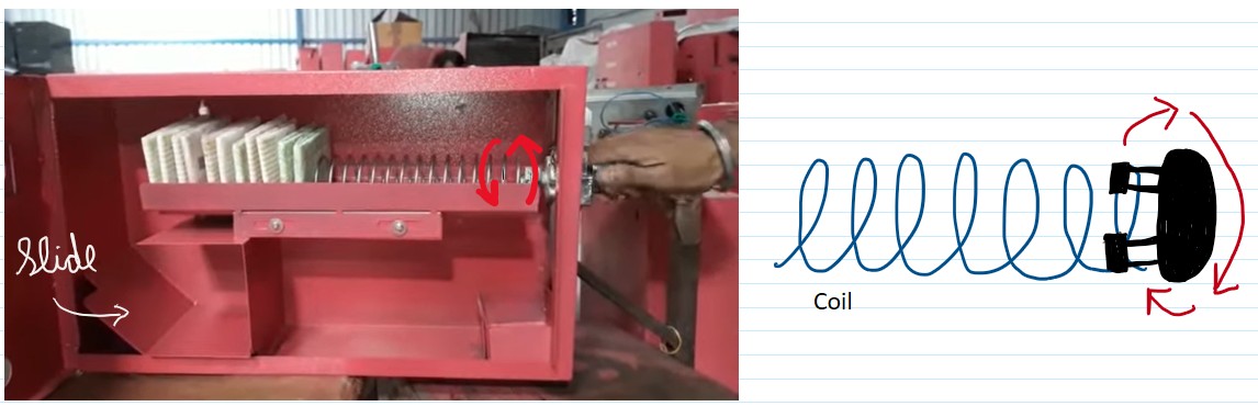
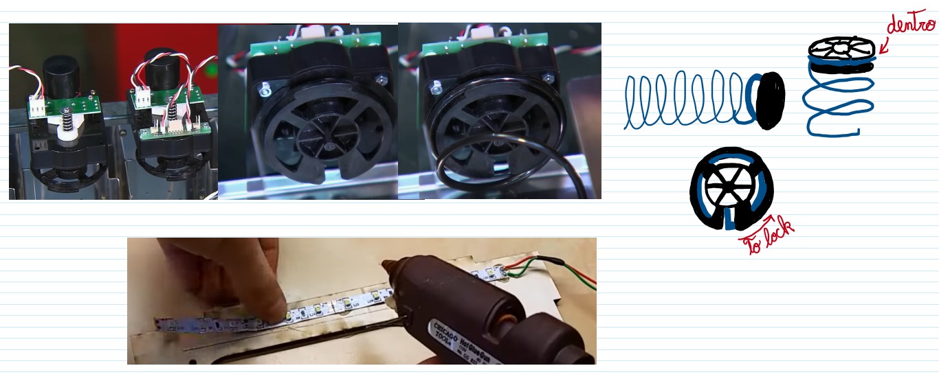
HigiBox was inspired by commercial sanitary pad vending machines and Arduino-based dispensers. These references showed me how rotating spirals could move products forward and how empty space below the storage area could contain electronics.
Initial Layout Strategy
Before detailed 3D modeling, I sketched how main systems could be arranged inside the enclosure:
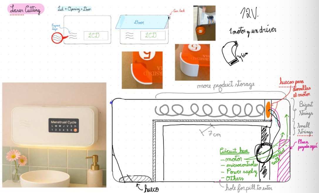
Sanitary pads and spiral mechanism occupy vertical storage area.
Motor placed next to spiral, requiring minimal vertical space.
Microcontroller, battery, drivers, and power modules positioned below.
Sensors, PCB, wiring, and battery in reserved side areas.
Enclosure Dimensions
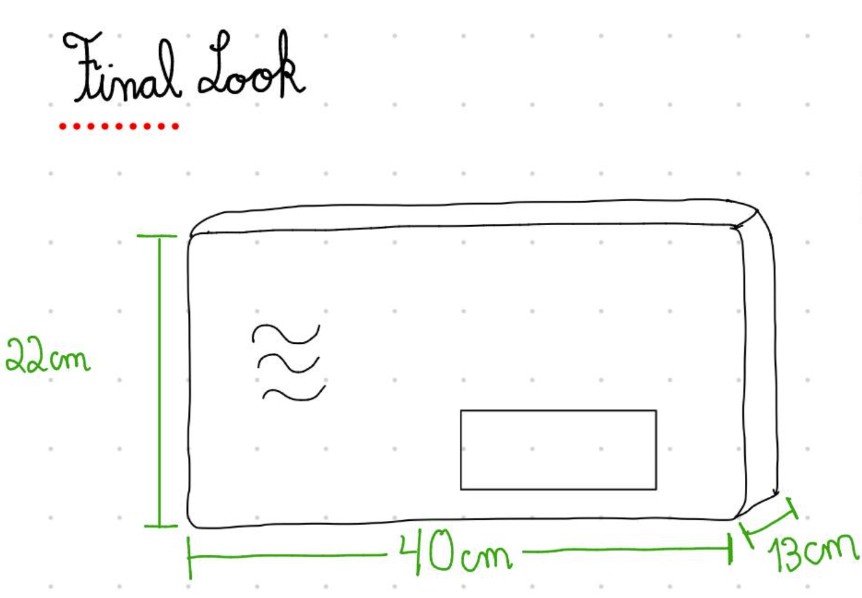
The first proposed enclosure provided enough space while maintaining compact form:
- Width: 40 cm
- Height: 22 cm
- Depth: 13 cm
3D Modeling and Spatial Planning
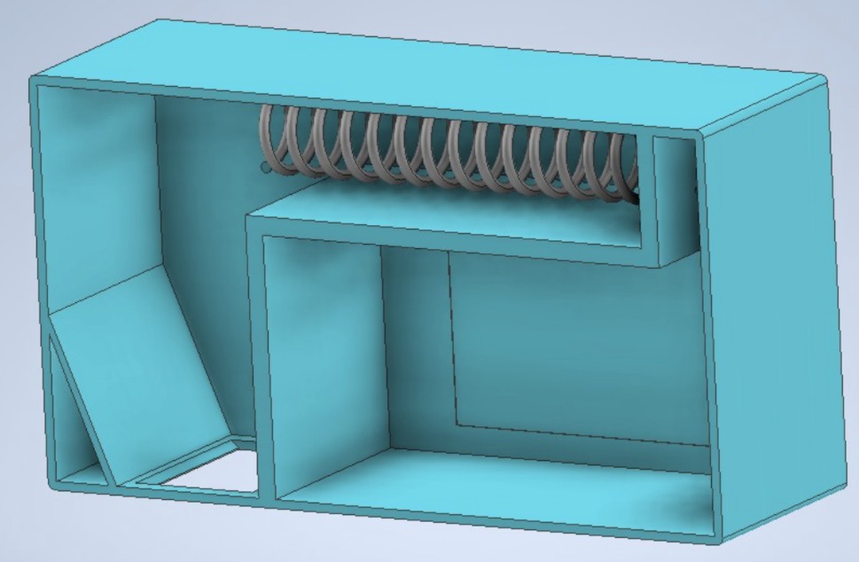
I began modeling the first version of the dispenser in Autodesk Inventor. This model was not intended to represent the final appearance of HigiBox. It was an initial draft that helped me understand the available internal space and check whether the storage area, dispensing spiral, motor, electronics, and product outlet could fit inside the proposed enclosure.
Functional Area Division
This draft allowed me to divide the product into functional areas. The spatial planning was crucial to ensure all systems could coexist:
Sanitary pads and spiral mechanism occupy vertical storage compartment. Spiral diameter and storage height determined by product dimensions.
Motor positioned next to spiral shaft to minimize horizontal space. ULN2003 driver mounted nearby for efficient wiring.
Microcontroller, custom PCB, and power regulation circuits occupy space below product storage area. Vertical stacking optimizes enclosure depth.
VL53L0X sensors, battery, INA219 sensor, and wiring routes placed in side areas. Enables modular assembly and future modifications.
Reference CAD Models from GrabCAD
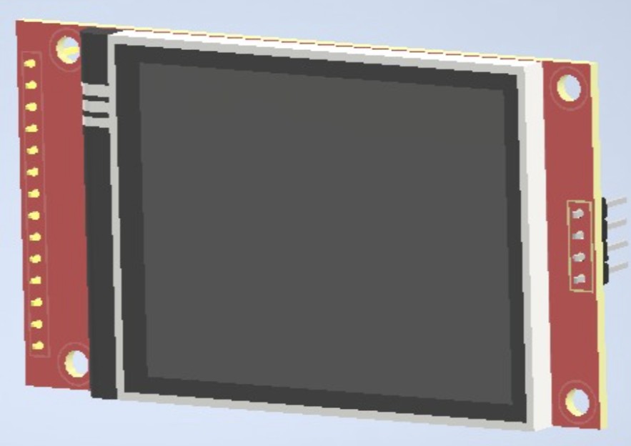
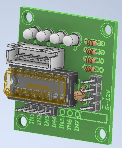
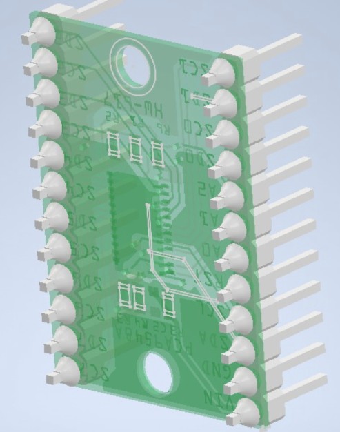
To obtain a more realistic representation, I downloaded reference CAD models of the electronic components. These models were not designed by me; they were used only to estimate the size and space required by each component inside the assembly:
Models included:
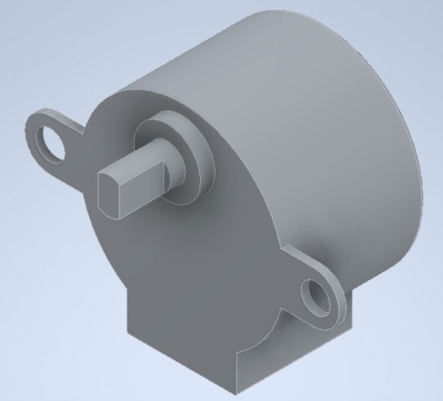
- Stepper motor (28BYJ-48)
- TFT display (2.8-inch)
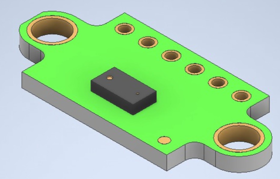
- Distance sensor (VL53L0X)
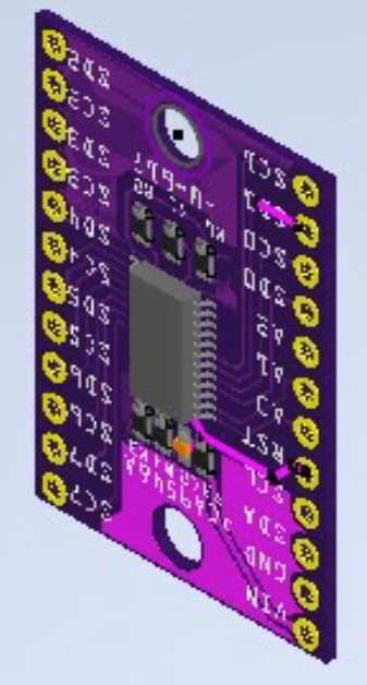
- I2C Multiplexer (TCA9548A)
- Motor driver (ULN2003)
- Other electronic modules
These reference models helped identify collision zones and evaluate different mounting positions before finalizing the design.
Component CAD references and assembly exploration:
Component Placement & Collision Detection
After importing the component models into Inventor, I placed them inside the enclosure to identify possible collisions and evaluate different mounting positions:
Verified clearances between motor and spiral storage, battery and electronics bay, sensors and mounting brackets.
Tested multiple configurations for PCB placement, sensor positioning, and cable routing paths.
Designed internal structure to allow maintenance access to battery, PCB connectors, and sensor cables.
Determined optimal assembly order: spiral frame → motor mount → electronics tray → wiring routes.
Exploded Assembly Visualization
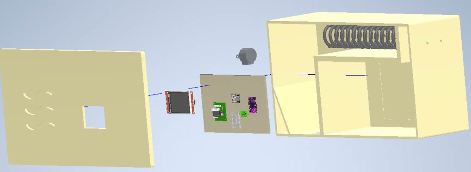
I also created an exploded assembly to visualize the relationship between all major components and understand the assembly process:
The yellow assembly version includes:
- Upper Spiral Compartment: Holds vertically stacked sanitary pads with rotating spiral mechanism
- Motor & Coupling: 28BYJ-48 stepper motor driving the spiral shaft rotation
- Front Display Panel: Opening for 2.8-inch TFT display with user interface
- Lower Electronics Area: PCB mounting plate with XIAO ESP32-C3, power regulation, and sensor connectors
- Internal Divisions: Barriers separating product storage from electronics to prevent contamination
- Access Door: Removable cover for battery replacement and maintenance
Assembly Relationships:
- Spiral shaft connects front bearing to motor coupling
- Motor bracket mounts securely to enclosure frame
- PCB mounting plate sits on support posts above battery compartment
- Display panel secured to front face with screws
- Sensor holders positioned at precise locations for hand detection and stock monitoring
Work-in-Progress Design Purpose
However, this assembly was still a work-in-progress model. Its primary purpose was to guide the integration process and help identify the remaining design decisions that needed to be made:
Define optimal paths for power wiring, I2C communication lines, and motor control cables. Minimize interference and mechanical stress.
Determine exact placement of VL53L0X sensors for reliable hand detection and stock monitoring. Account for optical line-of-sight requirements.
Select optimal battery position to balance weight distribution, minimize heat impact on other components, and allow USB-C access.
Define custom PCB size, connector locations, and mounting bracket design for secure positioning and vibration isolation.
Ensure design allows for battery replacement, PCB connector access, and sensor cleaning without complete disassembly.
Determine which parts to fabricate (laser-cut acrylic, 3D-printed components, custom PCB milling) versus purchase as assemblies.
Components Available for Integration
By this stage, I had all principal electronic components and materials ready for testing. This allowed evaluation of dimensions, connections, power requirements, and compatibility before finalizing the design.
Packaging Strategy
The rectangular enclosure would remain closed during normal operation, allowing the electronic system to be protected inside the dispenser. The internal layout divides the space into functional areas:
Upper section: Sanitary pads and spiral mechanism occupy vertical storage space.
Motor positioned next to spiral with ULN2003 driver nearby for space efficiency.
Custom PCB and microcontroller mounted on supporting structure below pads.
Battery, LM2596 converter, sensors, and wiring in lower and side areas.
Bill of Materials (BOM) with Images
| Component | Description | Source | Cost (USD) | Image |
|---|---|---|---|---|
| TFT LCD Display | 2.8-inch touchscreen for cycle, battery, stock info | Zacatrex Electrónica | $28.57 | 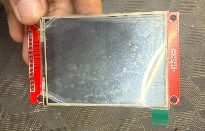 |
| TCA9548A Multiplexer | I2C bus multiplexer for dual sensors | Zacatrex Electrónica | $2.29 | 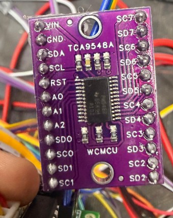 |
| ULN2003 Motor Driver | Controls the 28BYJ-48 motor coils | Zacatrex Electrónica | $1.43 | 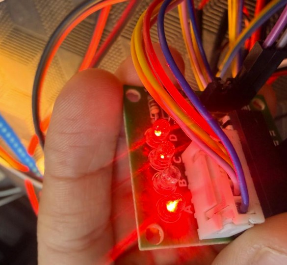 |
| 28BYJ-48 Stepper Motor | Rotates the dispensing mechanism | Fab Lab ULima | $2.86 | 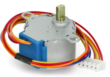 |
| LM2596 Converter | Step-down: 12V to 5V power regulation | Zacatrex Electrónica | $2.00 | 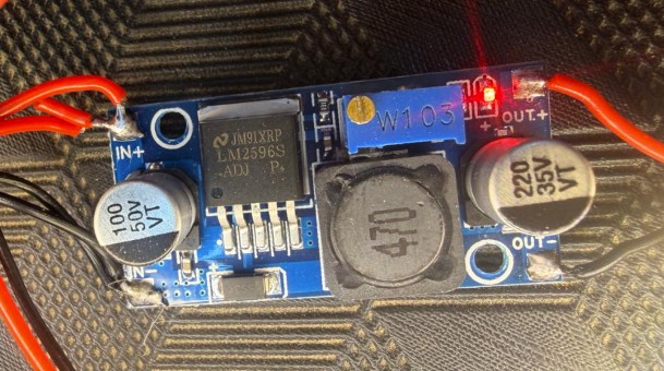 |
| INA219 Power Sensor | Voltage, current, and power monitoring | Zacatrex Electrónica | $5.71 | 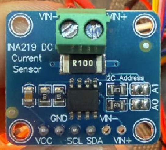 |
| 12V Rechargeable Battery | Powers the system with USB Type-C charging | Zacatrex Electrónica | $20.00 | 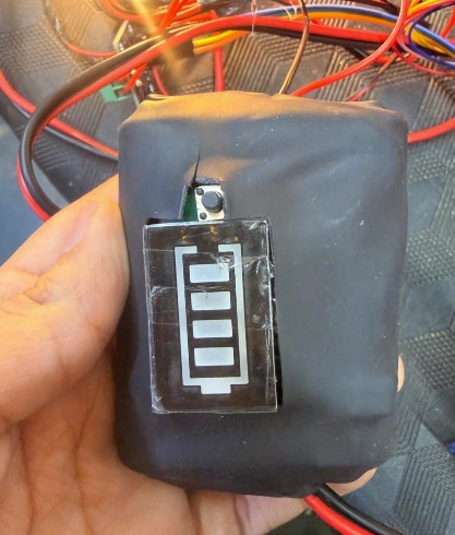 |
| VL53L0X Sensors (×2) | Time-of-Flight distance sensors for stock & hand detection | Zacatrex Electrónica | $6.86 | 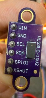 |
| Jumper Cables | For prototyping and integration testing | Fab Lab ULima | $1.43 | 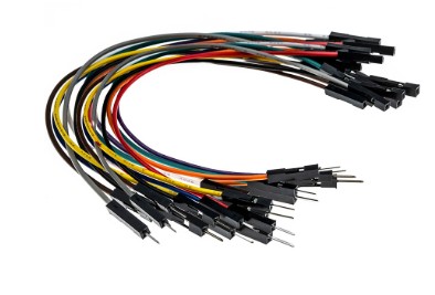 |
| White Acrylic (4mm) | Enclosure and internal divisions material | Fab Lab ULima | $30.00 |  |
| PolyLite White PLA | 3D printing material for supports & parts | Fab Lab ULima | $20.00 |  |
| PolyLite Black ABS | 3D printing material for stronger components | Fab Lab ULima | $18.57 |  |
| XIAO ESP32-C3 | Main microcontroller with Wi-Fi & Bluetooth | MTLab UNI | $14.29 | 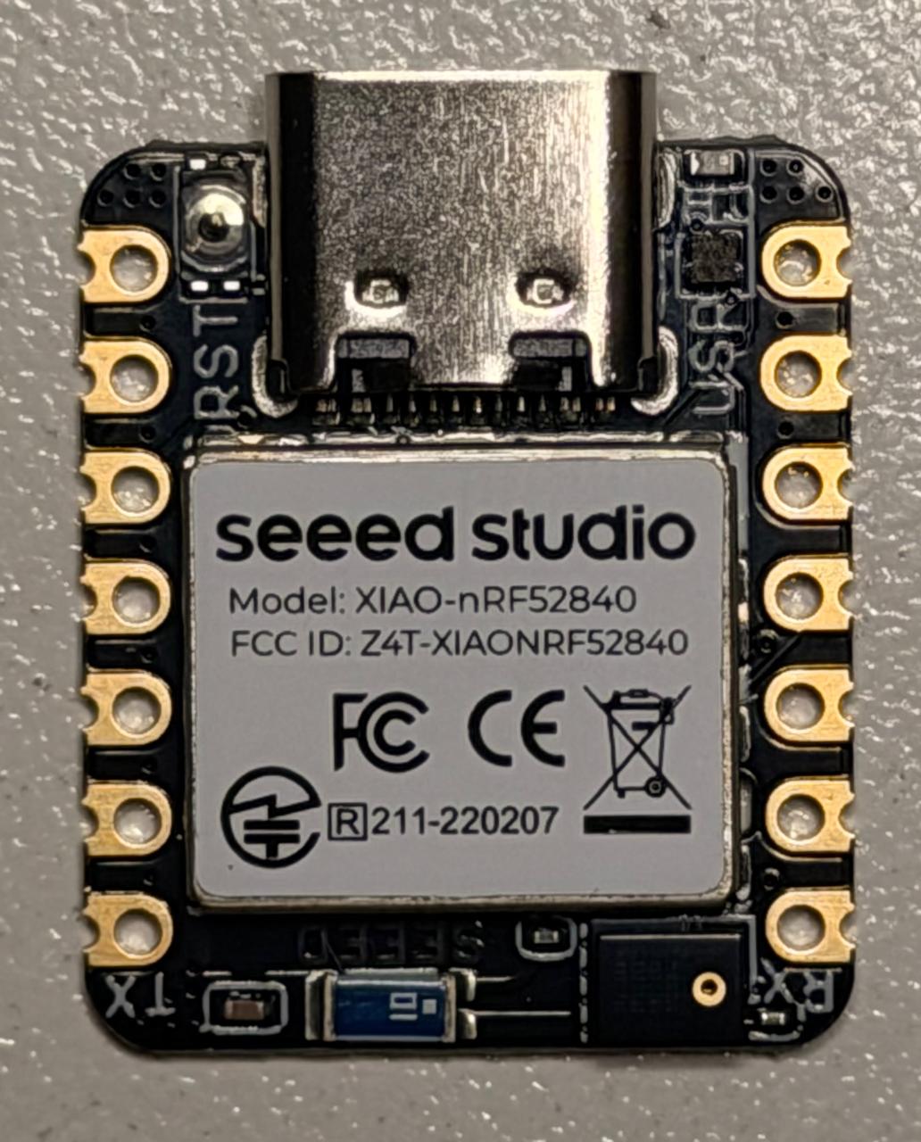 |
| Custom PCB Material | Copper-clad PCB for milling & manufacturing | Fab Lab ULima | $2.28 | 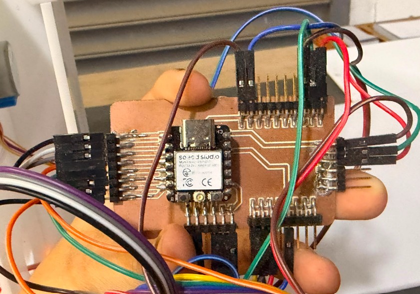 |
| TOTAL COST | USD 156.86 | |||
Parts to Be Fabricated
The following custom elements needed to be designed and manufactured specifically for HigiBox:
- Acrylic enclosure and internal divisions
- Custom PCB design and milling
- Rotating dispensing spiral
- Motor-to-spiral coupling mechanism
- Motor support structure
- Sensor holders and spacers
- PCB protective case
- Rounded enclosure corners
- Cable guides and internal mounts
- Control software and TFT interface
Individual Test of the VL53L0X
Distance sensing was essential because one sensor would monitor stock levels while another would detect the user's hand presence. I evaluated multiple sensor approaches before selecting the VL53L0X Time-of-Flight sensor.
Sensor Selection Process
Initially, I considered creating an infrared sensor using a separate emitter and receiver:
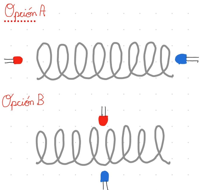
However, this solution required precise calibration and was affected by alignment and ambient light variations. I therefore selected the VL53L0X Time-of-Flight sensor, which uses an invisible infrared laser and communicates through I2C.
VL53L0X Sensor
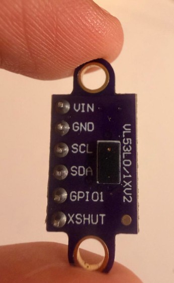
- Short distance: Sanitary pads are available
- Long distance: Compartment is empty or needs refilling
- Object detected: User hand present
- Distance threshold: < 100 mm triggers dispensing
First Test — Distance Reading
I first tested the sensor independently to understand its connections, measurement range, and response time before adding it to the complete system.
Test Code
#include <Wire.h>
#include <Adafruit_VL53L0X.h>

Adafruit_VL53L0X lox = Adafruit_VL53L0X();
const int pinLed = 8;

void setup() {
  Serial.begin(115200);
  pinMode(pinLed, OUTPUT);
  digitalWrite(pinLed, LOW);

  while (!Serial) { delay(1); }
  Serial.println("Starting VL53L0X test...");

  if (!lox.begin()) {
    Serial.println("Error finding VL53L0X! Check connections.");
    while (1);
  }
  Serial.println("VL53L0X ready.");
}

void loop() {
  VL53L0X_RangingMeasurementData_t measure;
  lox.rangingTest(&measure, false);

  if (measure.RangeStatus != 4) {
    int distancia = measure.RangeMilliMeter;
    Serial.print("Distance: ");
    Serial.print(distancia);
    Serial.println(" mm");

    if (distancia < 100) {
      digitalWrite(pinLed, HIGH);
    } else {
      digitalWrite(pinLed, LOW);
    }
  } else {
    Serial.println("Out of range or object too far.");
    digitalWrite(pinLed, LOW);
  }
  delay(1000);
}TFT Display Integration Challenge
The TFT display was one of the most difficult components to integrate, revealing important lessons about pin management and system architecture.
The Problem
Unlike the VL53L0X and INA219 sensors, the TFT display does not use I2C. It communicates through SPI and requires several dedicated control pins.
The display required D8 for the SPI clock signal. However, the second PCB version already used D8 for a button, while D7 was assigned to an LED.
This conflict prevented the screen from being connected correctly to the complete system, blocking further integration.
The Solution
I reviewed the XIAO ESP32-C3 pinout documentation, modified the PCB design, and reserved D8 specifically for the TFT display SPI connection.
Integration Tests and Validation
After testing individual modules separately, I combined them progressively. Each stage helped identify wiring, pin-assignment, programming, power, and communication problems before transferring to the custom PCB.
Focused on the VL53L0X sensor and XIAO ESP32-C3. Verified stable I2C communication and distance readings before connecting display, motor, or second sensor.
- XIAO ESP32-C3
- VL53L0X sensor
- I2C communication
Combined XIAO ESP32-C3, one VL53L0X sensor, TFT display, ULN2003 driver, and 28BYJ-48 motor.
- TFT displayed distance readings
- Motor activated when distance in range
- Programmed motor movement verified
Multiple modules on breadboards to inspect wiring, power connections, communication paths, and component arrangement.
The circuit required many jumper cables, demonstrating why a custom PCB was essential for final design.
Focused on graphical interface functionality and user experience displays.
- Menstrual cycle calendar
- Battery status information
- Stock availability
- Current cycle day
- Motivational messages
Combined two VL53L0X sensors, TCA9548A multiplexer, INA219, display, and XIAO ESP32-C3.
- TCA9548A separated dual sensors on I2C
- Both distances read simultaneously
- Battery info monitored in real time
- Display updated continuously
Software Integration and Power Diagram
Microcontroller Selection
Initially, I considered the XIAO nRF52840 for its compact size, low power, and Bluetooth. However, HigiBox required internet access for Wi-Fi time synchronization through an NTP server. The XIAO nRF52840 lacks integrated Wi-Fi, so I switched to the XIAO ESP32-C3.
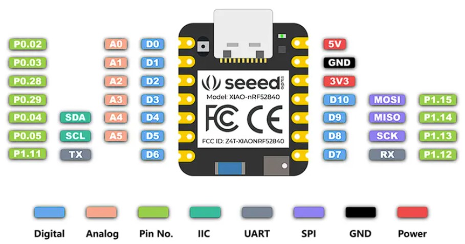
- Integrated 2.4 GHz Wi-Fi
- Bluetooth Low Energy
- Compact dimensions
- SPI for TFT display
- I2C for sensors
- Flexible GPIO control
- Serial monitor start
- Motor pin configuration
- SPI & TFT initialization
- I2C communication start
- Wi-Fi connection
- NTP time sync
- VL53L0X sensors init
- INA219 initialization
- First readings
- Display first screen
Power Distribution
Two power diagram versions show the evolution of the system design:
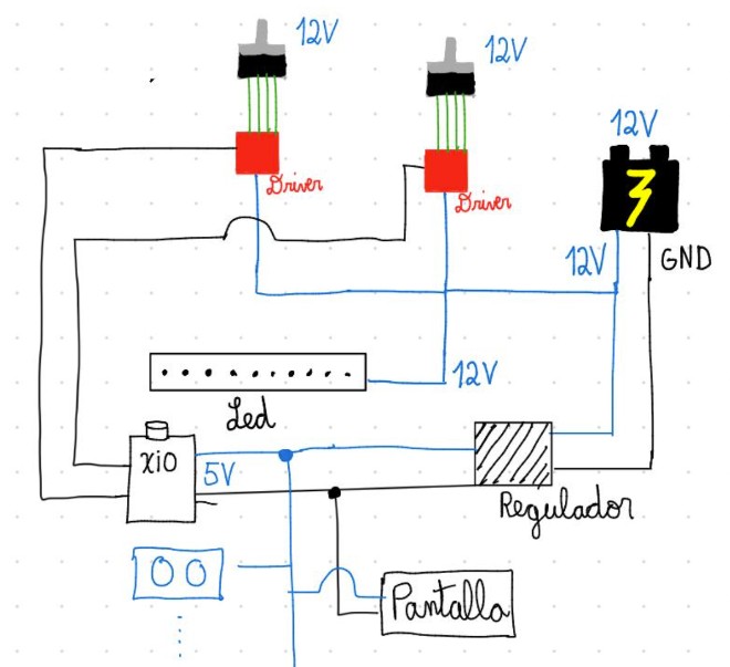
Before: Dual motor concept
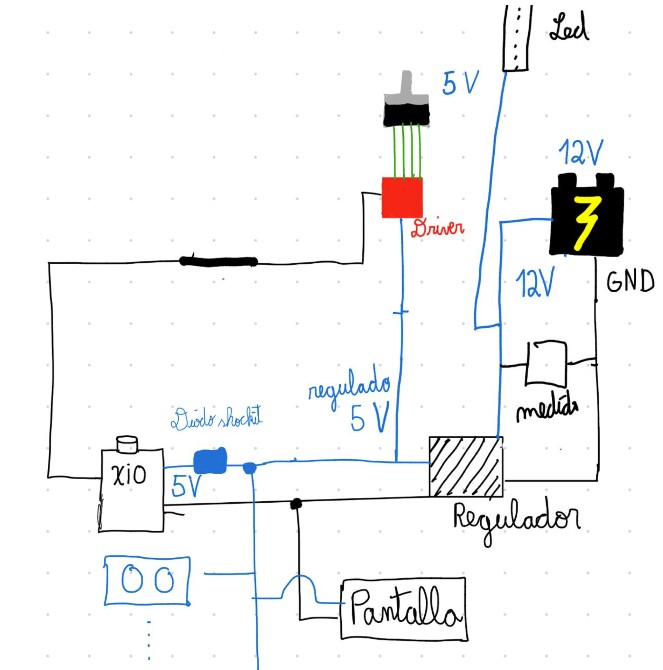
After: Single motor + multiplexer
Dispensing Logic
if (objetoCerca && stockPermite && !objetoAntes && !motorGirando) {
  girarUnaVuelta();
}
The motor activates only when: hand detected, dispensing permitted, detection is new, and motor not already moving. The objetoAntes variable prevents repeated dispensing while the user keeps their hand in front of the sensor.
PCB Evolution and Development
I manufactured three PCB versions during HigiBox development, each improving upon the previous design through iterative testing and refinement.
First PCB

The first board was too long for the internal space and eventually broke during testing. It demonstrated that the PCB needed to be smaller, stronger, and better adapted to the enclosure.
Second PCB
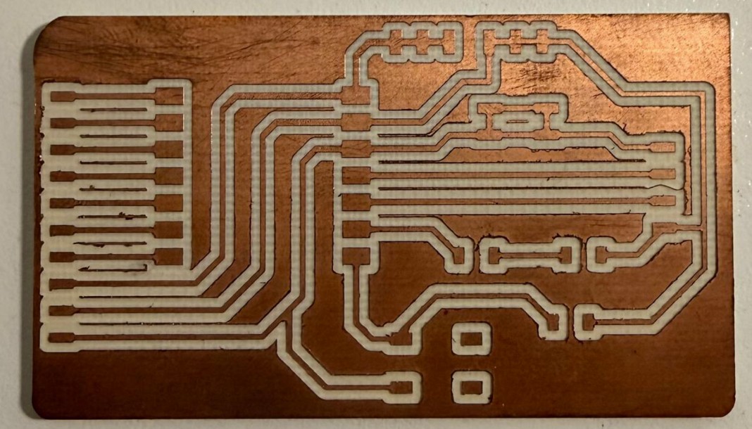
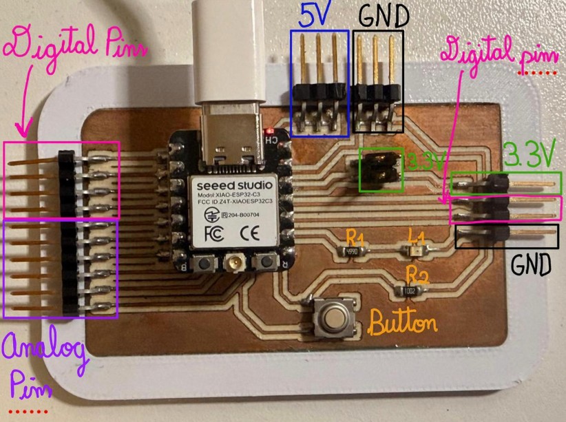
The second version was smaller with thicker traces, smoother routing, greater clearance, and improved milling offset. However, D8 and D7 were occupied by a button and LED, creating conflicts with the TFT display. Some connectors were also too close to the board edge.
Third and Final PCB
The third board corrected all pin conflicts and became the final PCB. It included:
- Eight 3.3V outputs
- Ten GND outputs
- Six 5V outputs
- Two D6 connections
- Two D7 connections
- D8 reserved for TFT SPI
These extensions allowed modules to connect directly to the custom PCB, eliminating external breadboards and reducing loose wiring.
PCB Case Design
After completing the final PCB, I designed a 3D-printed support to protect its edges and provide internal mounting points.
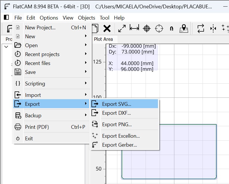
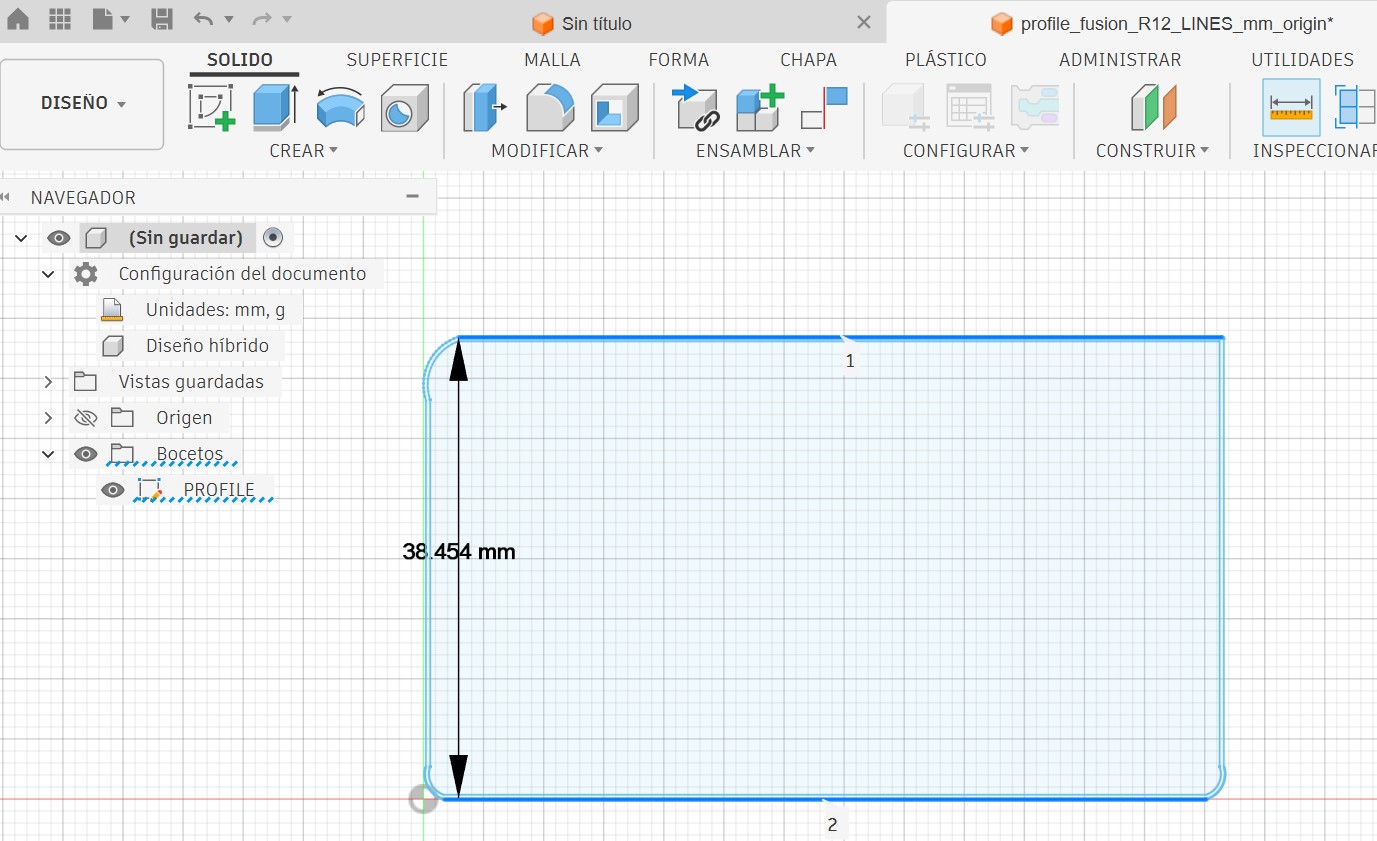
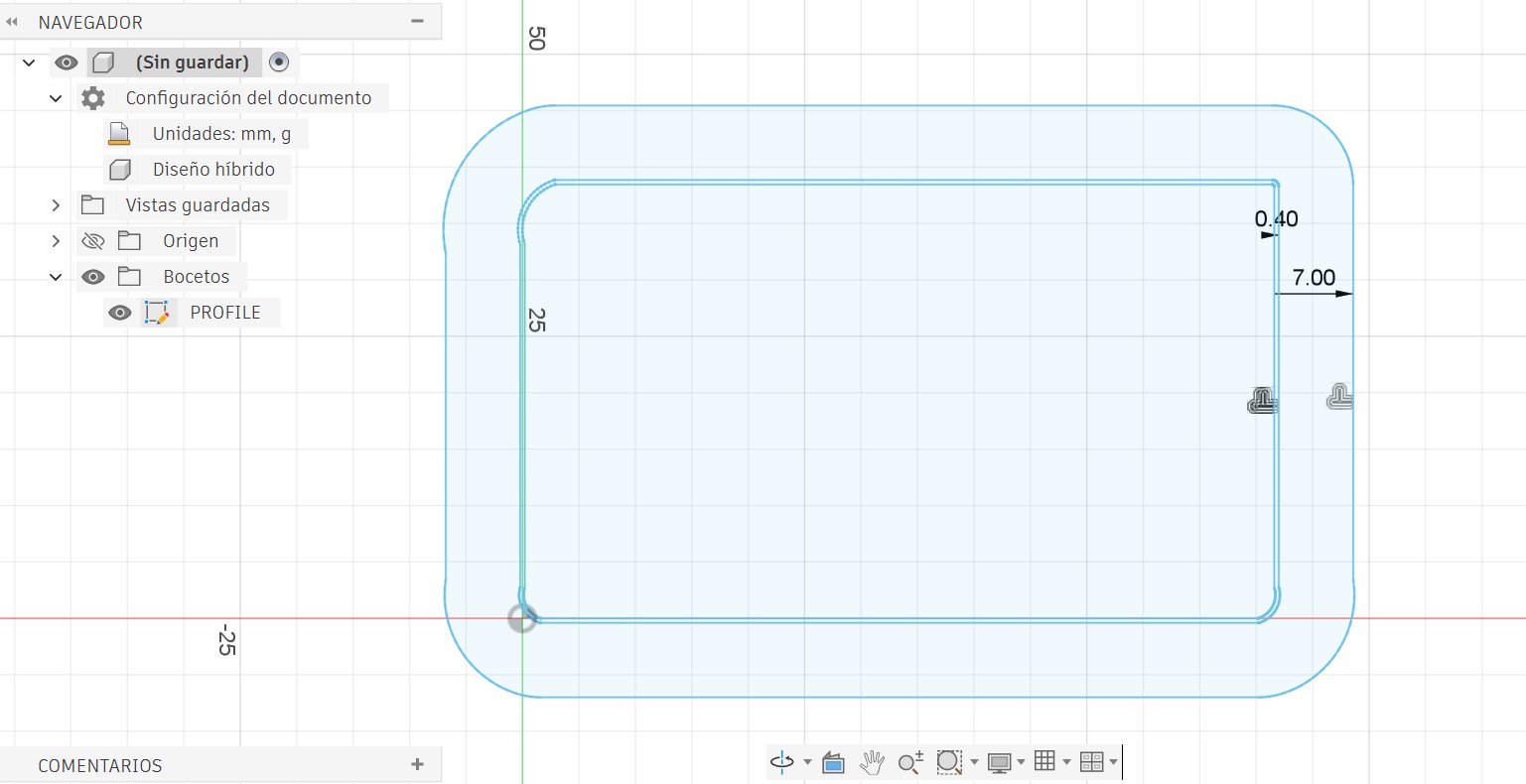
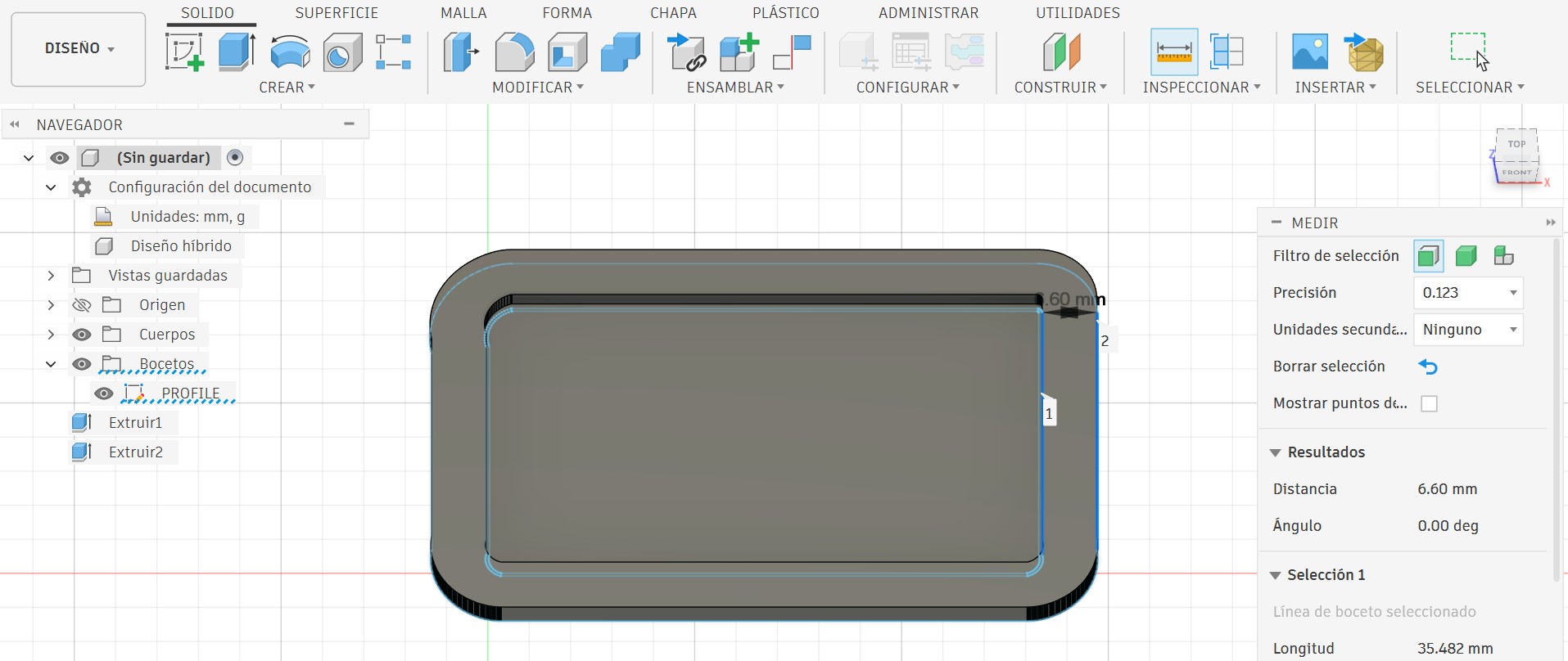
The PCB case included a 0.40mm FDM tolerance offset, 7mm external support offset, 1mm base, and 3mm outer ring to protect connectors and provide stable mounting inside the enclosure.
Final System Architecture
The integrated HigiBox system combines mechanical, electrical, and software components into a cohesive smart dispensing device. All systems work in concert through the central XIAO ESP32-C3 microcontroller.
Core Components
XIAO ESP32-C3 — Processes all sensor readings, updates the display, monitors battery, obtains the date through Wi-Fi, and controls the motor.
2.8-inch TFT Display — Shows menstrual cycle information, battery status, stock availability, and motivational messages in real time.
Two VL53L0X Sensors — One monitors stock levels, the other detects user hand presence through Time-of-Flight distance measurement.
28BYJ-48 Stepper + ULN2003 Driver — Rotates the dispensing spiral mechanism to release one sanitary pad per activation.
12V Battery + LM2596 Converter + INA219 — Powers the system with voltage regulation and real-time power monitoring.
Third-generation PCB — Routes all connections, manages I2C multiplexing, and provides mounting points for all modules.
Communication Protocols
Connects: VL53L0X sensors (via TCA9548A multiplexer), INA219 power sensor. Provides multi-device support with address multiplexing.
Connects: 2.8-inch TFT display. Provides high-speed graphics rendering and real-time interface updates.
Connects: Motor coils via ULN2003 driver. Provides stepper motor control for dispensing mechanism.
Connects: NTP server for time synchronization. No internet gateway required for basic operation.