
The Architecture of an Interface: Bridging Two Worlds
To master this week's assignment, I had to understand how the Physical World (my custom board) talks to the Digital World (my computer application). This communication happens through three essential layers that must work in perfect harmony.
The code used to write the instructions. Two languages work as a team: C++ (Arduino) running on the XIAO ESP32C3, handling hardware inputs and outputs; and Python on the computer, creating the visual interface and processing data.
The rules that define how data is organized so both devices understand each other. Serial sends data in a continuous stream; protocols like UDP or MQTT package information into wireless "envelopes".
The physical or wireless channel through which data travels. A USB cable provides a direct, stable connection; Wi-Fi/Bluetooth enables mobility using the ESP32C3's built-in wireless capabilities.
Communication Strategy & Hardware Setup
After experiencing limitations with my previous board's lack of networking capabilities in Week 11, I upgraded to the XIAO ESP32-C3 for Week 15. This microcontroller's integrated internet support provides the reliable connectivity my final project requires.
To connect my hardware with the digital interface, I structured the communication into three layers, ensuring a stable link between the XIAO ESP32C3 and my computer.
C++ on the microcontroller, Python on the PC. Python was chosen for its efficiency in handling GUI libraries and data processing.
Serial Communication at 9600 baud. Based on Week 11 logic, this ensures a synchronized, continuous data stream.
USB-C Cable. A wired connection was selected to eliminate latency, interference, and wireless pairing complexity.
Python + Serial + USB provides the most robust plug-and-play setup for real-time interaction between UI and hardware.
Technical Specs
| Component | Detail |
|---|---|
| Microcontroller | XIAO ESP32-C3 |
| Library (PC) | pyserial |
| Library (GUI) | Tkinter |
| Connection | Wired USB Serial @ 9600 baud |
| Output Device | LED on Pin D7 |
| Command Protocol | 'H' = LED ON, 'L' = LED OFF |
The Board & Arduino Programming
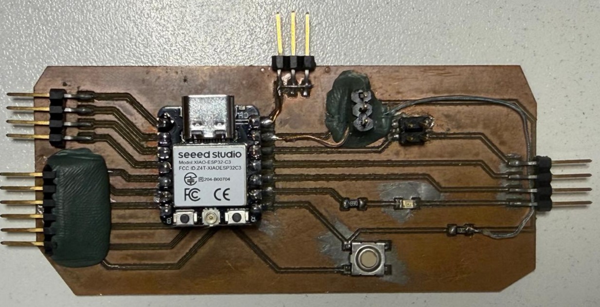
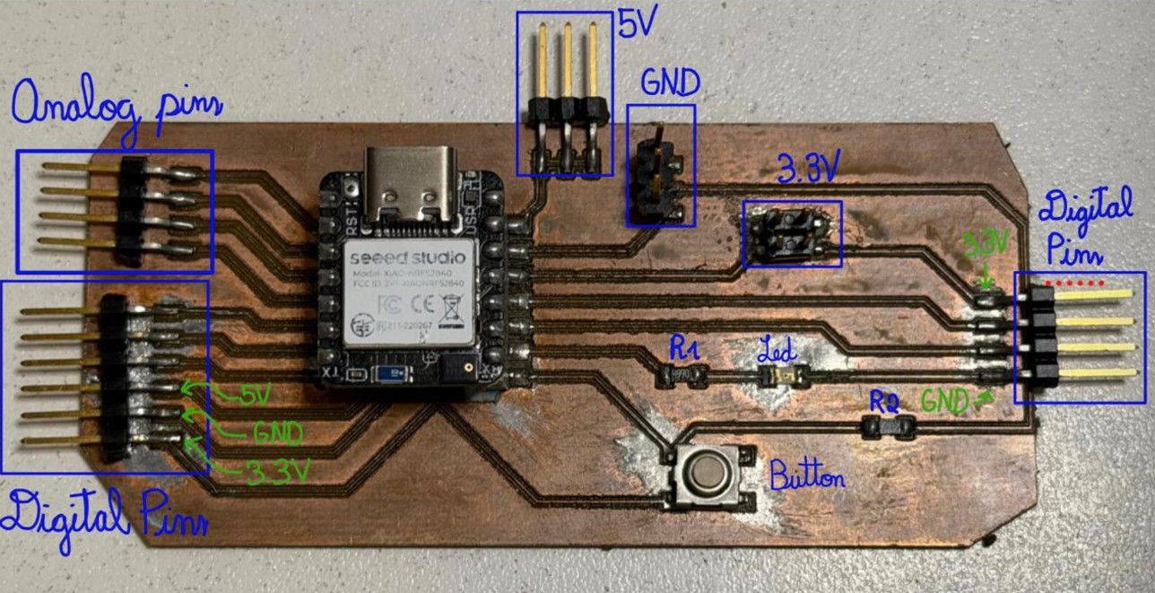
For this week's assignment, I used the board made during Week 8: Electronics Production, which has serial communication pins enabled and an LED as output.
Arduino Setup — Quick Guide
Plug your board into the computer and ensure the COM3 port is recognized in Device Manager.
In File > Preferences, paste the official Espressif board manager URL into the "Additional Boards Manager URLs" field.
Open the Boards Manager (left icon), search for ESP32, and click Install on the Espressif Systems package.
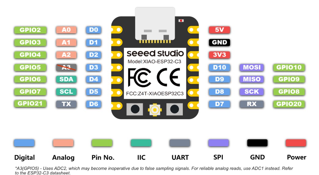
Navigate to Tools > Board > esp32 and manually select XIAO_ESP32C3 from the list to enable the correct pin configuration.
Select the correct COM port under Tools > Port and upload your sketch. The board's built-in LED will blink to confirm a successful flash.
The board is configured to monitor the serial buffer for incoming data: an 'H' signal activates the GPIO pin, while an 'L' signal deactivates it.
// Week 15: Interface and Application Programming
// Board: XIAO ESP32-C3
// Component: LED on Pin D7

const int ledPin = D7;

void setup() {
  Serial.begin(9600);
  pinMode(ledPin, OUTPUT);
  digitalWrite(ledPin, LOW);
}

void loop() {
  if (Serial.available() > 0) {
    char incomingByte = Serial.read();

    if (incomingByte == 'H') {
      digitalWrite(ledPin, HIGH);   // Turn LED ON
      Serial.println("LED turned ON");
    }
    else if (incomingByte == 'L') {
      digitalWrite(ledPin, LOW);    // Turn LED OFF
      Serial.println("LED turned OFF");
    }
  }
}Sets GPIO D7 HIGH — the LED turns on. Sends confirmation message back over serial.
Sets GPIO D7 LOW — the LED turns off. Sends confirmation message back over serial.
Python GUI — Spyder, Tkinter & pySerial
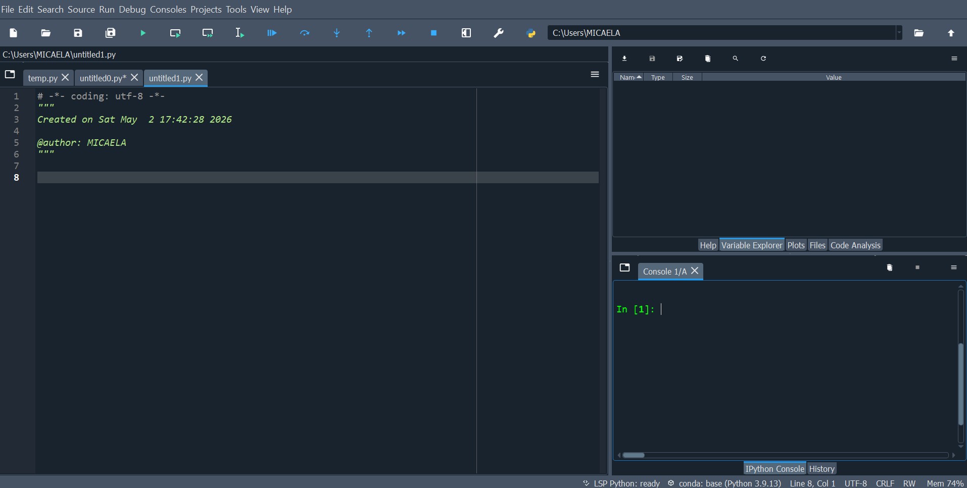
I chose to work with Python because I was already familiar with it from university courses in data analysis and charting. For the IDE, I opted for Spyder — a Scientific Python Development Environment with integrated debugging, interactive execution, and library management.
I implemented the Spyder Standalone version to maintain a dedicated environment for hardware projects, keeping it independent from other Python installations on my system.
Setting Up pySerial in Spyder
If you are new to Spyder 5, certain libraries may not be pre-installed. First, verify if pySerial is available by running in the IPython Console:
try:
    import serial
    print("Library 'pyserial' is already installed!")
except ImportError:
    print("Library 'pyserial' NOT found.")
If you get a ModuleNotFoundError, force the installation directly into Spyder's internal path using this command in the IPython Console:
import subprocess
import sys

# Forces Spyder to install in its own executable folder
subprocess.check_call([sys.executable, "-m", "pip", "install", "pyserial"])Confirm the installation succeeded with a clean verification:
import serial
print("Success! Library is ready to use.")This code uses the Tkinter library for the graphical interface and PySerial to establish a robust communication link with the XIAO ESP32-C3 microcontroller.
import tkinter as tk
from tkinter import ttk, messagebox
import serial
import serial.tools.list_ports
# --- Window Configuration ---
root = tk.Tk()
root.title("Micaela's Interface - ESP32 Control")
root.geometry("400x300")
root.configure(bg='#f0f0f0')
arduino = None
# --- Control Functions ---
def connect_board():
global arduino
port = port_selector.get()
try:
arduino = serial.Serial(port, 9600, timeout=1)
status_label.config(text=f"Status: Connected to {port}", foreground="green")
messagebox.showinfo("Success", f"Connected to {port} successfully!")
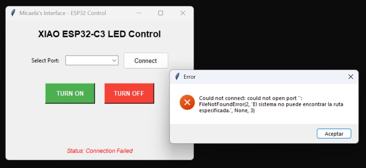
except Exception as e:
status_label.config(text="Status: Connection Failed", foreground="red")
messagebox.showerror("Error", f"Could not connect: {e}")
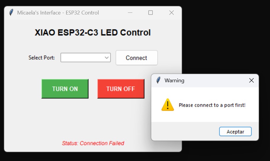
def send_signal(state):
if arduino and arduino.is_open:
arduino.write(state.encode())
print(f"Signal sent: {state}")
else:
messagebox.showwarning("Warning", "Please connect to a port first!")
# --- UI Elements ---
style = ttk.Style()
style.configure("TButton", padding=6, font=('Helvetica', 10))
title_label = tk.Label(root, text="XIAO ESP32-C3 LED Control",
font=('Helvetica', 14, 'bold'), bg='#f0f0f0')
title_label.pack(pady=15)
# Port Selector
frame_port = tk.Frame(root, bg='#f0f0f0')
frame_port.pack(pady=10)
tk.Label(frame_port, text="Select Port:", bg='#f0f0f0').grid(row=0, column=0, padx=5)
available_ports = [p.device for p in serial.tools.list_ports.comports()]
port_selector = ttk.Combobox(frame_port, values=available_ports, width=15)
port_selector.grid(row=0, column=1, padx=5)
if available_ports: port_selector.current(0)
btn_connect = ttk.Button(frame_port, text="Connect", command=connect_board)
btn_connect.grid(row=0, column=2, padx=5)
# Action Buttons
btn_frame = tk.Frame(root, bg='#f0f0f0')
btn_frame.pack(pady=20)
btn_on = tk.Button(btn_frame, text="TURN ON", bg="#4CAF50", fg="white",
font=('Helvetica', 10, 'bold'), width=12, height=2,
command=lambda: send_signal('H'))
btn_on.grid(row=0, column=0, padx=10)
btn_off = tk.Button(btn_frame, text="TURN OFF", bg="#F44336", fg="white",
font=('Helvetica', 10, 'bold'), width=12, height=2,
command=lambda: send_signal('L'))
btn_off.grid(row=0, column=1, padx=10)
# Status Label
status_label = ttk.Label(root, text="Status: Disconnected",
font=('Helvetica', 9, 'italic'))
status_label.pack(side="bottom", pady=10)
root.mainloop()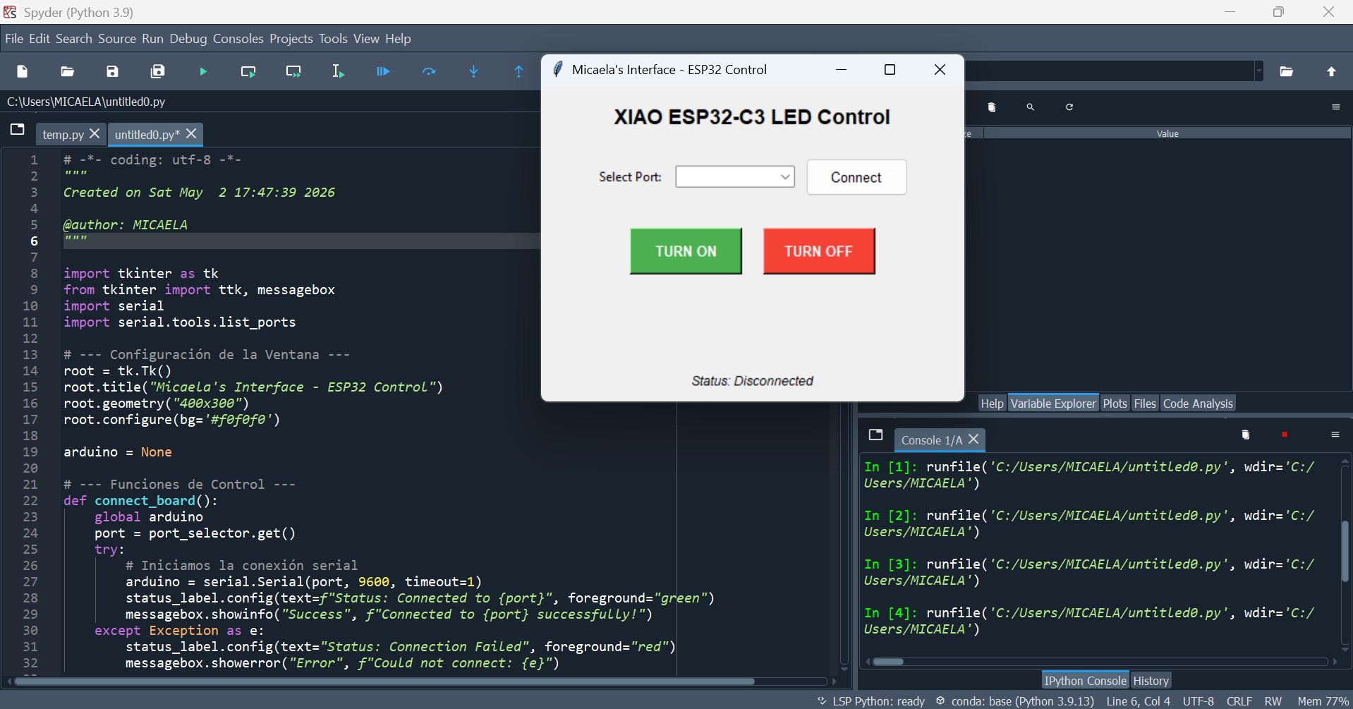
Key Features & Final Result
I implemented a port detection system using serial.tools.list_ports, allowing users to select the active COM port through a ttk.Combobox dropdown that auto-populates all available ports on launch.
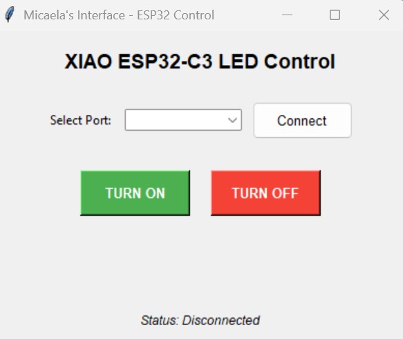
The interface sends encoded bytes ('H' for ON, 'L' for OFF) via a 9600 baud serial connection to toggle the board's digital pins. The board echoes back a confirmation message visible in the Spyder console.
To ensure a robust, business-ready design, I added exception handling with visual pop-up alerts and clear color-coded buttons providing immediate visual feedback on connection status.
- Serial Port Conflict: Ensure the Arduino Serial Monitor is closed before running the Python script; the COM port will appear as "busy" and the connection will fail.
- Execution Order: Upload the Arduino code first. Once complete, run the Spyder script. They cannot share the serial port simultaneously.
- Resetting the App: If you need to restart, close the GUI, verify the Arduino status, then run the Spyder code again to re-establish the link.
GUI Tool Comparison — App Inventor vs Python
MIT App Inventor is a visual, block-based programming environment specifically designed for creating Android applications. Its logic is very similar to Scratch, making it extremely intuitive for those familiar with puzzle-piece programming.
- Drag-and-drop design without writing code
- Ideal for rapid mobile visualization
- Built-in blocks for Bluetooth, GPS, and sensors
- QR code to test live on real phone instantly
- Restricted to predefined components
- Primarily focused on Android platform
- Limited AI integration (manual block mapping)
- Less suitable for complex serial USB workflows
First Impressions — "Hello Codi!" App
As part of my interface research, I experimented with MIT App Inventor following a tutorial to create the "Hello Codi!" app, where touching a bee triggers a sound effect.
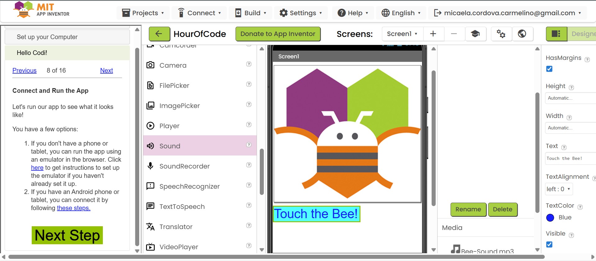
Every element (Button, Sound, Label) functions as an independent object with customizable properties — similar to how components work in modern UI frameworks.
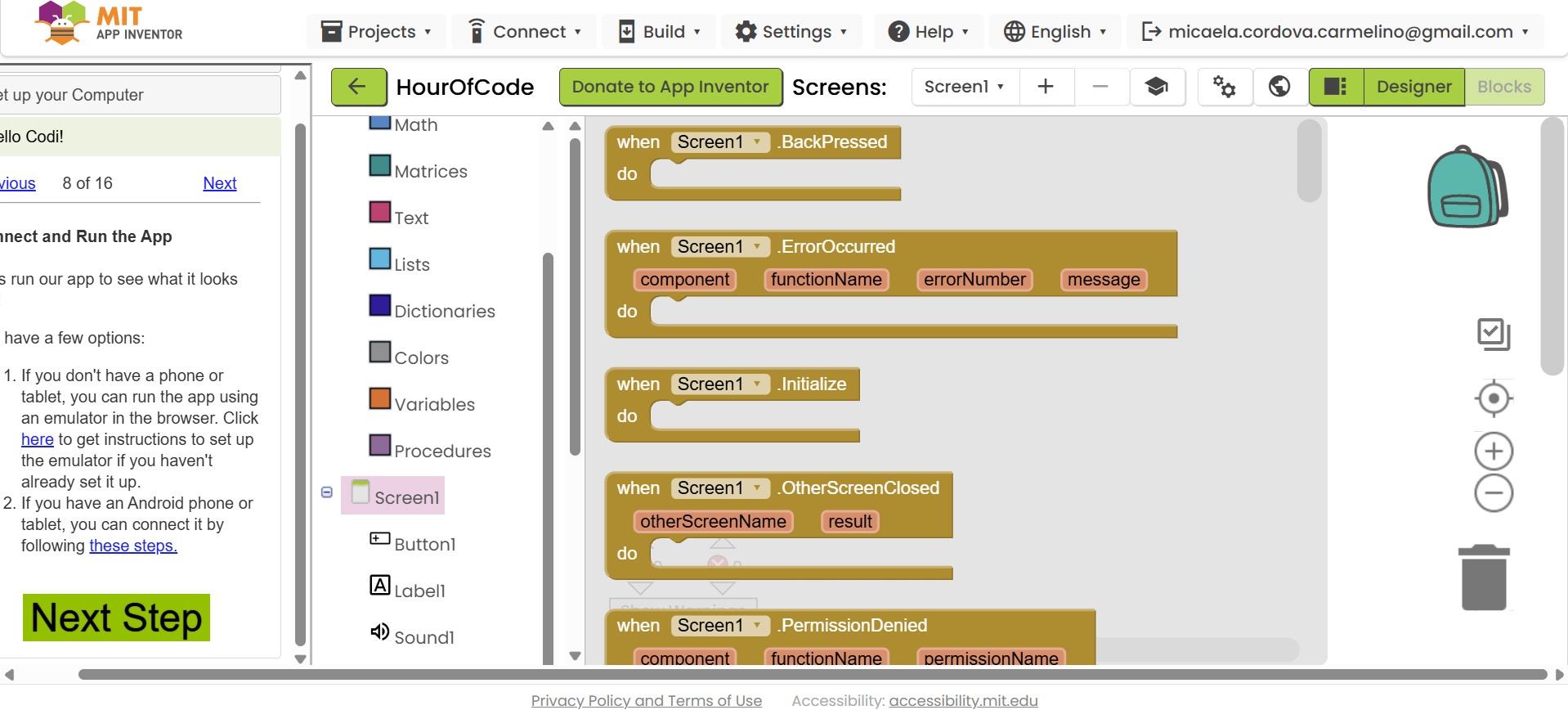
Using the Blocks editor, I managed visual logic through action blocks like when Button1.Click — without writing a single line of manual code.
Python is a high-level language and Tkinter is its standard library for creating Desktop Graphical User Interfaces (GUIs). This combination gives total control over logic, appearance, and advanced libraries.
- Total control over logic and appearance
- AI-friendly — easily generate, paste, and debug code with tools like Gemini or ChatGPT
- Cross-platform: same script runs on Windows, macOS, and Linux
- Robust USB Serial integration via pySerial
- Requires understanding of programming syntax and logic
- Coding a layout takes more time than dragging components
- Desktop-only (Tkinter does not target mobile)
Development Workflow
| Feature | MIT App Inventor | Python (Tkinter) |
|---|---|---|
| Logic Style | Block-based (like Scratch) | Text-based scripting |
| Primary Target | Mobile users (Android) | Desktop users (Win/Mac/Linux) |
| Hardware Link | Bluetooth / Wi-Fi | USB Serial (COM ports) |
| AI Integration | Limited (manual block mapping) | High (copy/paste code logic) |
| Learning Curve | Very low — drag and drop | Medium — requires syntax knowledge |
| Customization | Restricted to built-in components | Unlimited control |
| Best For | Quick mobile prototyping | Robust desktop + serial projects |