
Inspiration & Planning
At the beginning of the week, we decided to develop a minimalist CNC machine because it combines mechanical design, electronics, software control, and digital fabrication in one integrated system. Our main inspiration came from small desktop CNC machines and from a YouTube playlist by Prof. Garcia — CNC Fácil de Hacer en Casa — where he explains the process of building a CNC machine step by step.
Design Decisions
Based on our research, we adapted the idea to the materials and components available in our lab. We focused on creating a compact CNC machine capable of moving in the X, Y, and Z axes, using a proven and accessible combination of components:
Lead screws, linear bearings, hardened steel shafts, flexible couplings, and aluminum profiles.
Arduino Uno with GRBL firmware, CNC Shield, A4988 stepper drivers, and a 12V power supply.
Aspire for G-code generation and OpenBuilds CONTROL for machine operation and axis jogging.
This planning stage helped us define the machine structure, select the required components, and organize the fabrication process before starting the assembly.
The Design
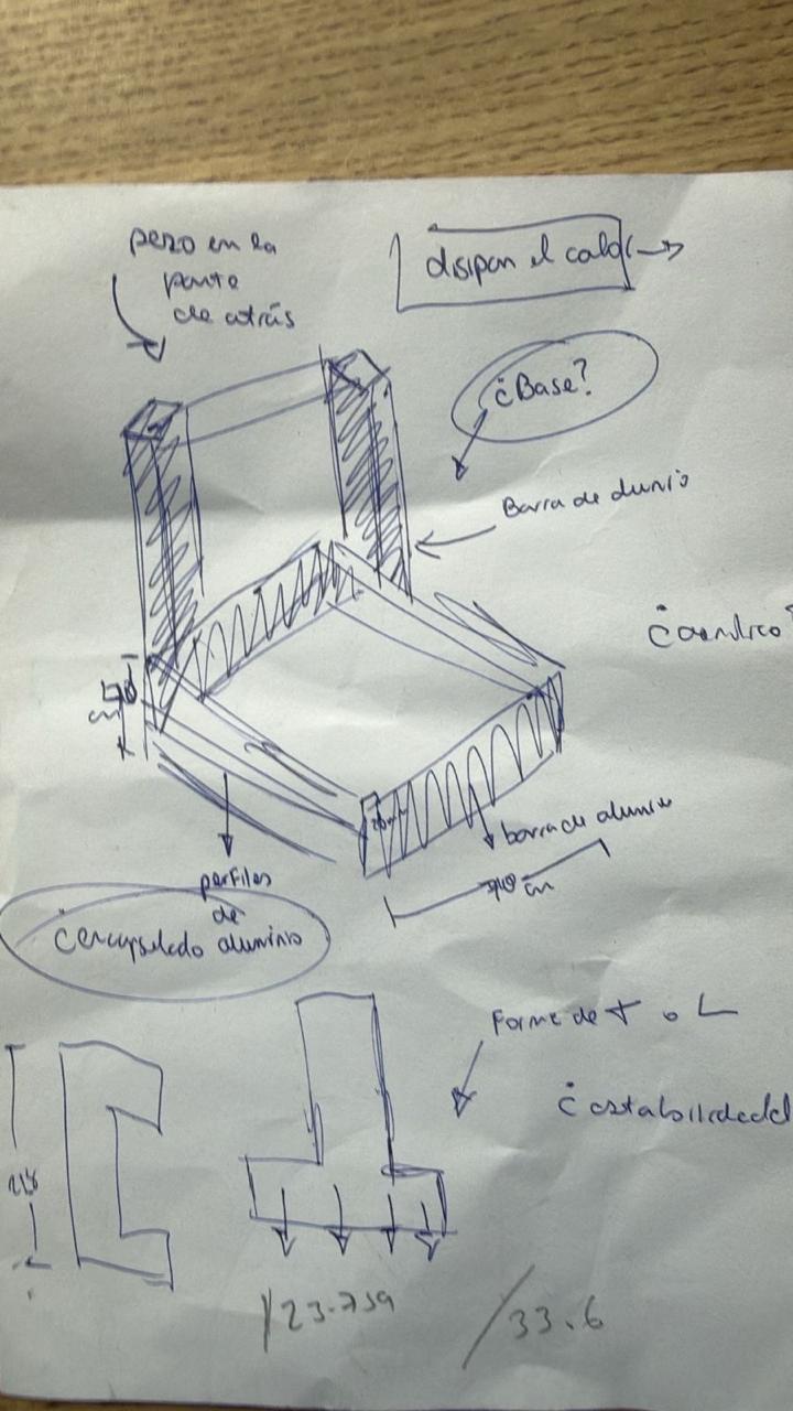
The first stage was to design the main structure of the CNC machine in Autodesk Inventor. Before modeling the full machine, we started with an initial sketch to understand the general shape, the position of the axes, and the space that each component would need.
Individual Parts in Inventor
After defining the concept, we created the main parts of the CNC machine in Inventor. Each component was modeled separately — the base, side supports, moving bed, motor supports, and axis plates — to understand the dimensions of each piece before assembling the complete machine.


Full Assembly
All parts were then placed into an Inventor assembly file. This allowed us to visualize the complete CNC structure and verify how the mechanical elements work together — checking the position of the motors, lead screws, shafts, couplings, bearings, acrylic plates, and aluminum profiles.


DXF Export & Laser Cutting
One advantage of using Inventor was that we could generate the 2D profiles needed for fabrication. From the 3D model, we selected the flat faces of the structural pieces and exported them as DXF files. These files were used to laser cut the acrylic components.
Laser cutting — acrylic plate 1
Laser cutting — acrylic plate 2
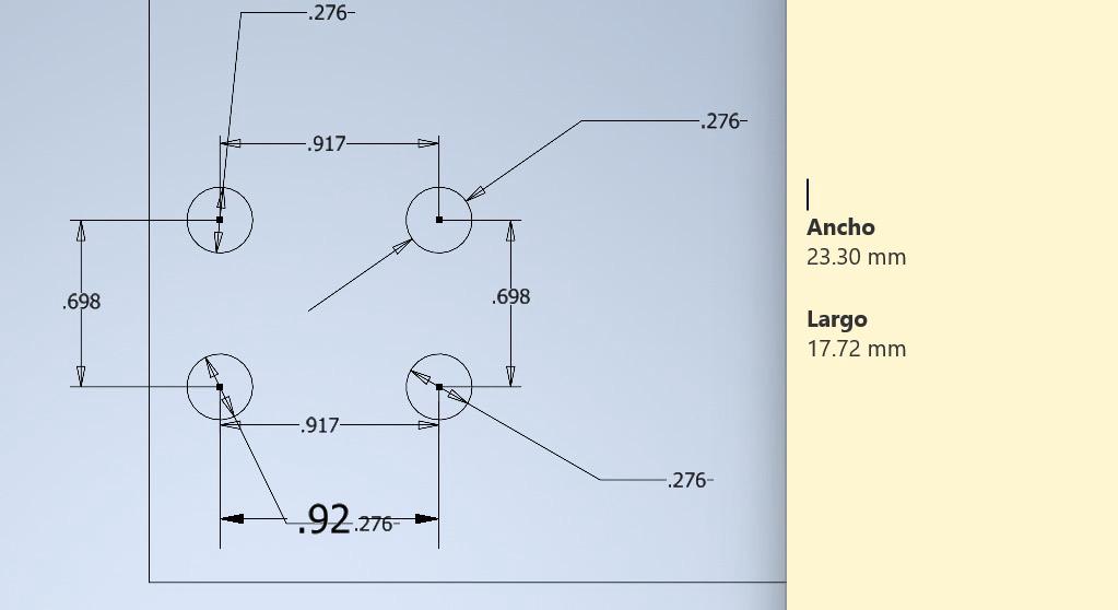
One of my main individual contributions was helping to correct the measurements of the digital model using the real physical components. Although the first Inventor model helped us understand the general structure, some dimensions did not match perfectly once we started assembling the real machine.
Redesigned acrylic plates
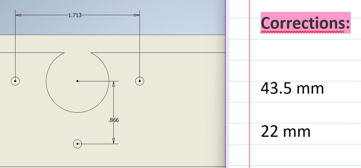
Hole correction for motor alignment
In some cases, the holes in the fabricated parts did not match the real position of the motor or mechanical supports. Some corrections were made directly on the pieces by manually adjusting the holes; other parts had to be redesigned and cut again.
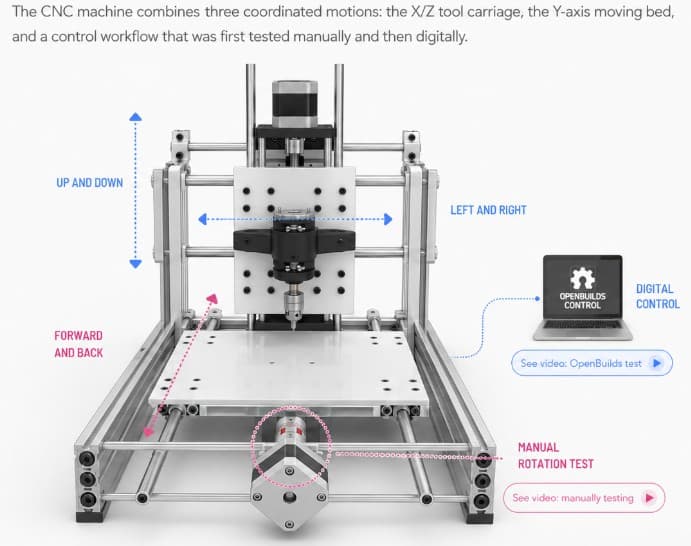
Mechanism & Motion System
Mechanism diagram — created with ChatGPT based on the machine's description
Moves the carriage from left to right along the guide shafts. Driven by a lead screw connected to a stepper motor through a flexible coupling.
Moves the tool up and down to approach or lift from the work surface. This positions the tool correctly before engraving, drawing, or cutting.
The central carriage holds the tool and controls the working movement. Together, the X and Z axes allow precise tool positioning in two dimensions before the operation begins.
The lower bed moves the material forward and backward (Y axis). During the first assembly stages, we manually tested this axis by rotating the rods through the couplings installed in the acrylic bed — verifying that the movement was smooth and aligned before connecting power.
Manual Y-axis testing — rotating the lead screw by hand
After the manual verification, the machine was controlled using OpenBuilds CONTROL. From the laptop, we jogged the axes, moved the bed and the motorized system, and established the work origin before running a G-code job — confirming that the mechanical and electronic systems were working together correctly.
Digital axis testing with OpenBuilds CONTROL
| Component | Specs | Function |
|---|---|---|
| Flexible shaft couplings | 8 mm × 3 | Connect stepper motor shafts to lead screws |
| Lead screws | 8 mm Ø, ~40 cm × 3 | Convert rotational motion into linear movement |
| Lead screw nuts | × 3 | Move along lead screws and transfer motion to moving parts |
| Linear ball bearings | 8 mm × 12 | Smooth guided linear movement along steel shafts |
| Hardened steel shafts | 8 mm Ø, ~40 cm × 5 | Guide movement of the carriage and bed |
| Shaft supports | 8 mm × 2 | Hold and align guide shafts for structural stability |
| Standard bearings | 8 mm × 3 | Support rotating parts and reduce friction |
| Laser-cut acrylic plates | — | Bed, structural supports, and mounting surfaces |
| Aluminum profiles | — | Main structural frame of the machine |
| 3D-printed support parts | — | Specific holders and mechanical adaptations |
| Tool / spindle holder | — | Holds the engraving, drawing, or cutting tool |
| Fasteners | M3 screws, nuts, spacers | Assemble and secure all mechanical parts |
| Component | Details | Role |
|---|---|---|
| Arduino Uno + GRBL | GRBL firmware | Main controller — interprets G-code commands |
| CNC Shield | — | Interfaces Arduino with motor drivers; distributes STEP & DIR signals |
| A4988 stepper drivers | × 3 | Control current and movement of each stepper motor |
| Stepper motors | × 3 | Generate movement for X, Y, and Z axes |
| 12V power supply | External | Powers the stepper motors through the CNC Shield |
| USB connection | Laptop → Arduino | Sends G-code commands from control software |
| Wires & connectors | — | Connect motors, drivers, shield, and power supply |
Vector design tool for creating machining toolpaths and exporting G-code files (.ngc).
Free machine-control platform. Connects laptop to CNC, jogs axes, sets work origin, and runs G-code jobs.
Installed on the Arduino Uno. Converts G-code into motion-control instructions for the CNC machine.
Used for the 3D modeling, mechanical design, assembly verification, and DXF export of the CNC structure.
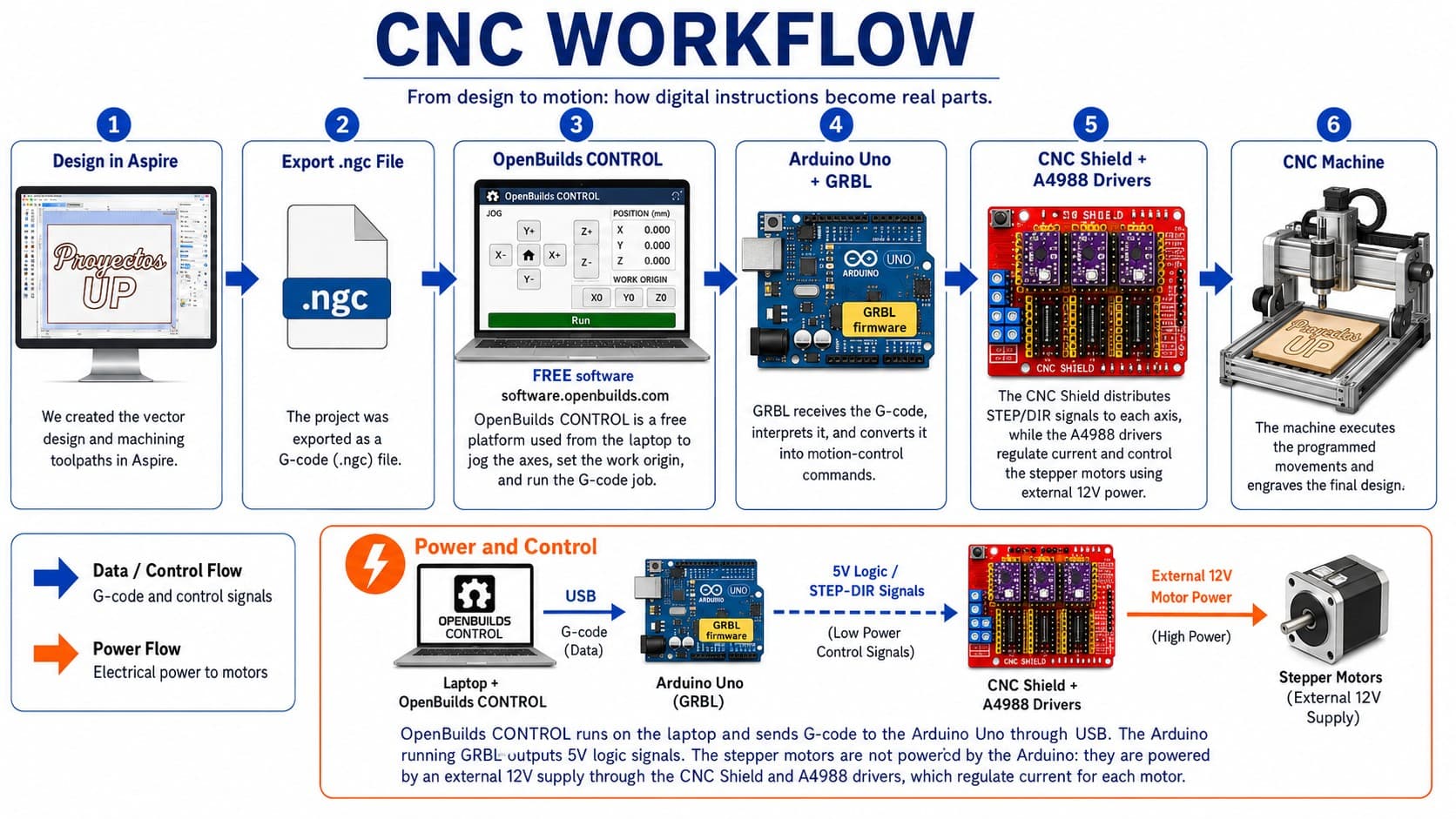
CNC Workflow
For this machine, we followed a digital workflow that connected the design process, G-code generation, machine control software, electronics, and the physical movement of the CNC machine into one seamless pipeline.
Full CNC workflow demonstration video
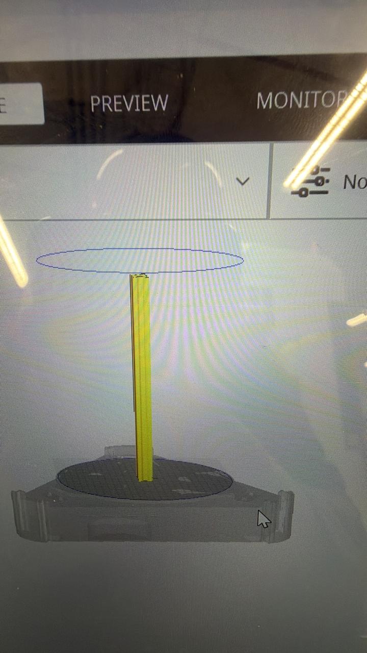
We created the vector design in Aspire. The design used for this test was the text "UP". We prepared the drawing, generated the machining toolpaths according to the material and type of operation, then exported the project as a G-code file with the .ngc extension.
The .ngc file was opened in OpenBuilds CONTROL, available at software.openbuilds.com. This free platform allowed us to connect the laptop to the CNC controller, load and execute the G-code file, manually move the machine axes, and set the work origin before starting the job.
OpenBuilds CONTROL sent the G-code from the laptop to the Arduino Uno through a USB connection. The Arduino was running GRBL firmware, which interprets G-code commands and converts them into motion-control instructions.
The Arduino sends low-power 5V logic signals (STEP and DIR) — not motor power. The CNC Shield works as an interface between the Arduino and the motor drivers, organizing the connections for each axis and distributing control signals to the corresponding A4988 stepper drivers.
The A4988 stepper motor drivers receive the 5V control signals and use an external 12V power supply to drive the stepper motors. The Arduino does not convert 5V to 12V — the A4988 drivers use the logic signals to switch and regulate the external motor power. They also control the current delivered to each motor for accurate step-by-step movement.
The CNC machine executed the programmed movements and engraved the "UP" design onto the material. Through this workflow, a digital vector design was transformed into a physical machined result.
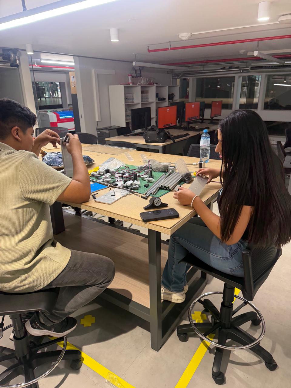
Mechanical Fabrication Process
After completing the 3D model, we started the mechanical fabrication process by checking the real components and preparing the materials for assembly. We compared the digital design with the physical parts — aluminum profiles, motors, shafts, couplings, screws, and support pieces.
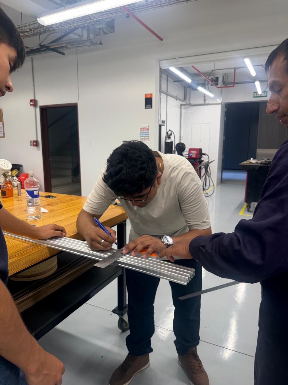
We measured the aluminum profiles and marked the required dimensions. This step was critical — the frame needed to match the Inventor model dimensions and support the movement system correctly.
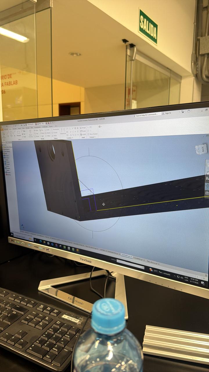
Before machining any metal parts, we reviewed the design in Inventor to verify the geometry of pieces that had to be manufactured — checking shape, dimensions, and hole positions before sending parts to fabrication.
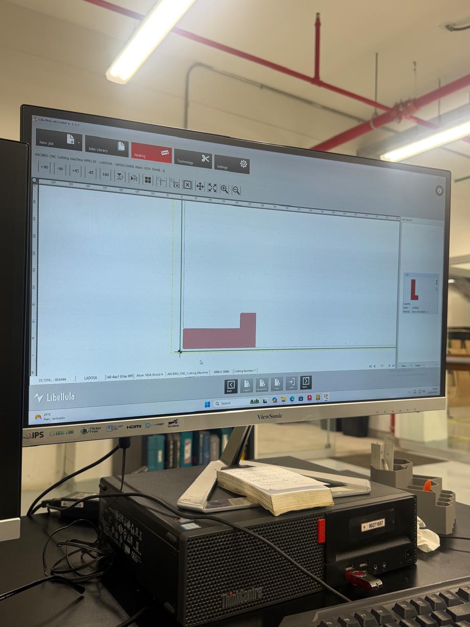
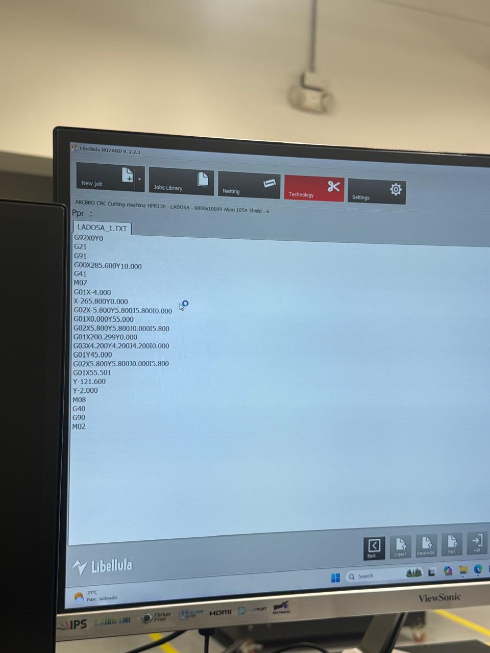
For the metal fabrication process, we used CAM software to prepare the cutting paths. We tested and reviewed the geometry in programs such as EdgeCAM and Libellula before machining — verifying the toolpath and generating the necessary instructions for the CNC machine.
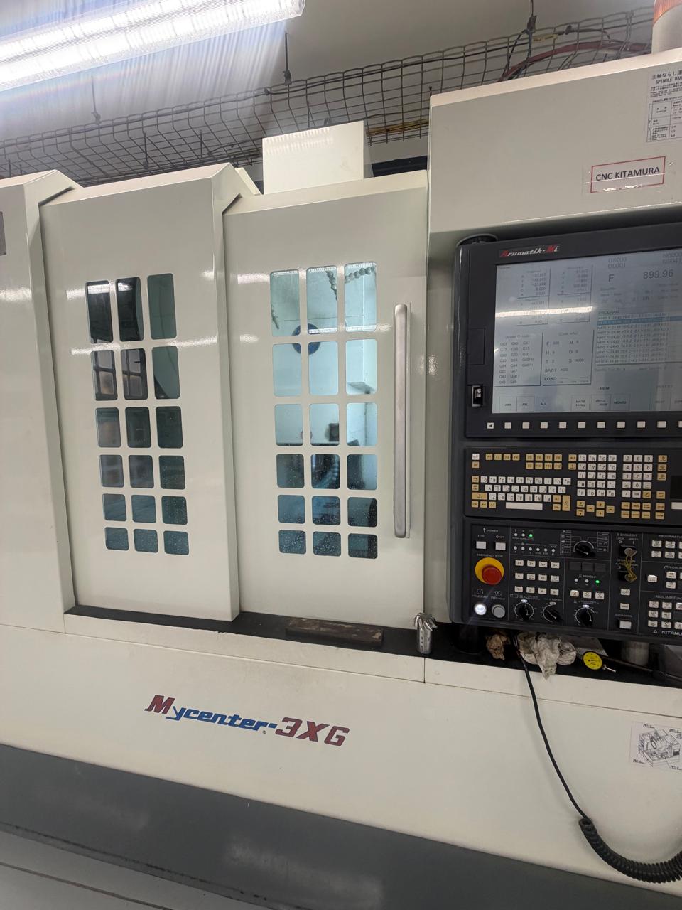
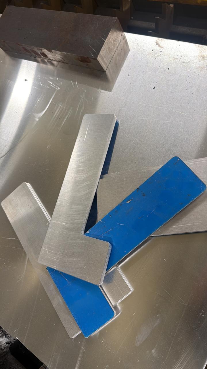
We used the CNC metal-cutting machine to manufacture some of the structural metal parts. This process was useful for creating stronger components for the frame and supports of the machine.
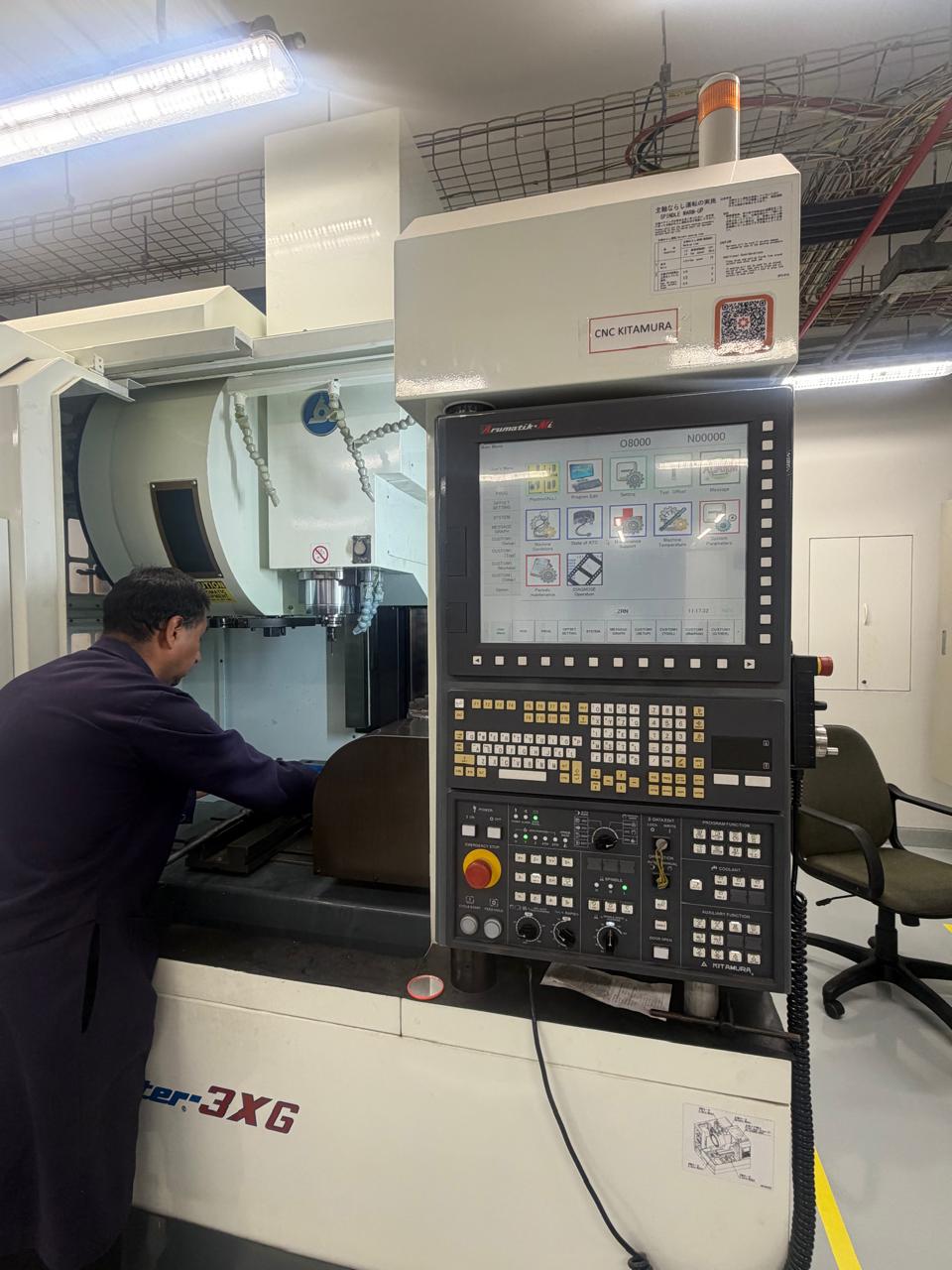
After cutting the metal pieces, we checked the results and prepared them for the next assembly steps. Some parts required additional adjustments to improve the fit with real components.
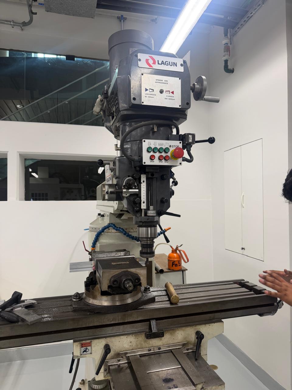
We also used a milling / drilling machine to make or correct holes in some of the metal parts. This was necessary because the holes had to align correctly with the motors, couplings, screws, and structural supports.
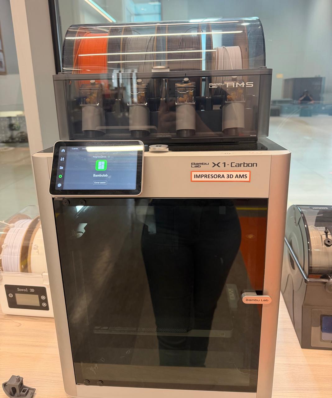
In addition to the metal parts, we fabricated some support components using 3D printing. These pieces were useful for prototype adjustments because they were faster to produce and easier to modify than metal.
Results
The first operational test confirmed that the machine could drill holes and draw straight lines. This validated the basic motion system, the GRBL communication, and the G-code execution pipeline.
First result — hole drilling and line drawing test
The machine was tested on wood, demonstrating that it could apply enough force and maintain accurate positioning for drilling operations on a real material.
Wood drilling — take 1
Wood drilling — take 2
We added a pen holder to the tool mount, enabling the machine to draw continuous paths. This test demonstrated the machine's precision for vector-based drawing operations, tracing smooth lines from the G-code path.
Pen drawing — run 1
Pen drawing — run 2

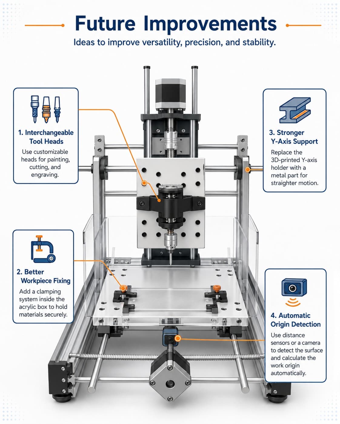
Illustration generated with ChatGPT based on the improvement concepts described above

Machine Design — Week 12
Together we designed, fabricated, assembled, and tested the CNC machine. Each member contributed from their strengths — 3D modeling, electronics, fabrication, and documentation — to bring the machine from a sketch to a working tool.