Week 9 Progress Checklist
| Status | Task |
|---|---|
| ✓ | Linked to the group assignment page |
| ✓ | Documented what you learned from interfacing an input device(s) to your microcontroller and optionally, how the physical property relates to the measured results. |
| ✓ | Documented your design and fabrication process or linked to the board you made in a previous assignment. |
| ✓ | Explaind how your code works. |
| ✓ | Explained any problems you encountered and how you fixed them. |
| ✓ | Included original design files and source code. |
| ✓ | Included a ‘hero shot’ of your board. |
Input Devices
Group Assignment
1. Testing an analog sensor
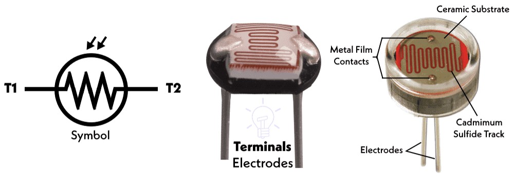
1.1 Testing a LDR - Light Dependent Resistor
It is also commonly known as a photoresistor or a photocell. As the name suggests, it is a type of resistor whose resistance changes depending on the amount of light falling on its surface . It's a passive component, meaning it doesn't generate electricity but rather modifies an electrical signal .
Connections to the microcontroller:
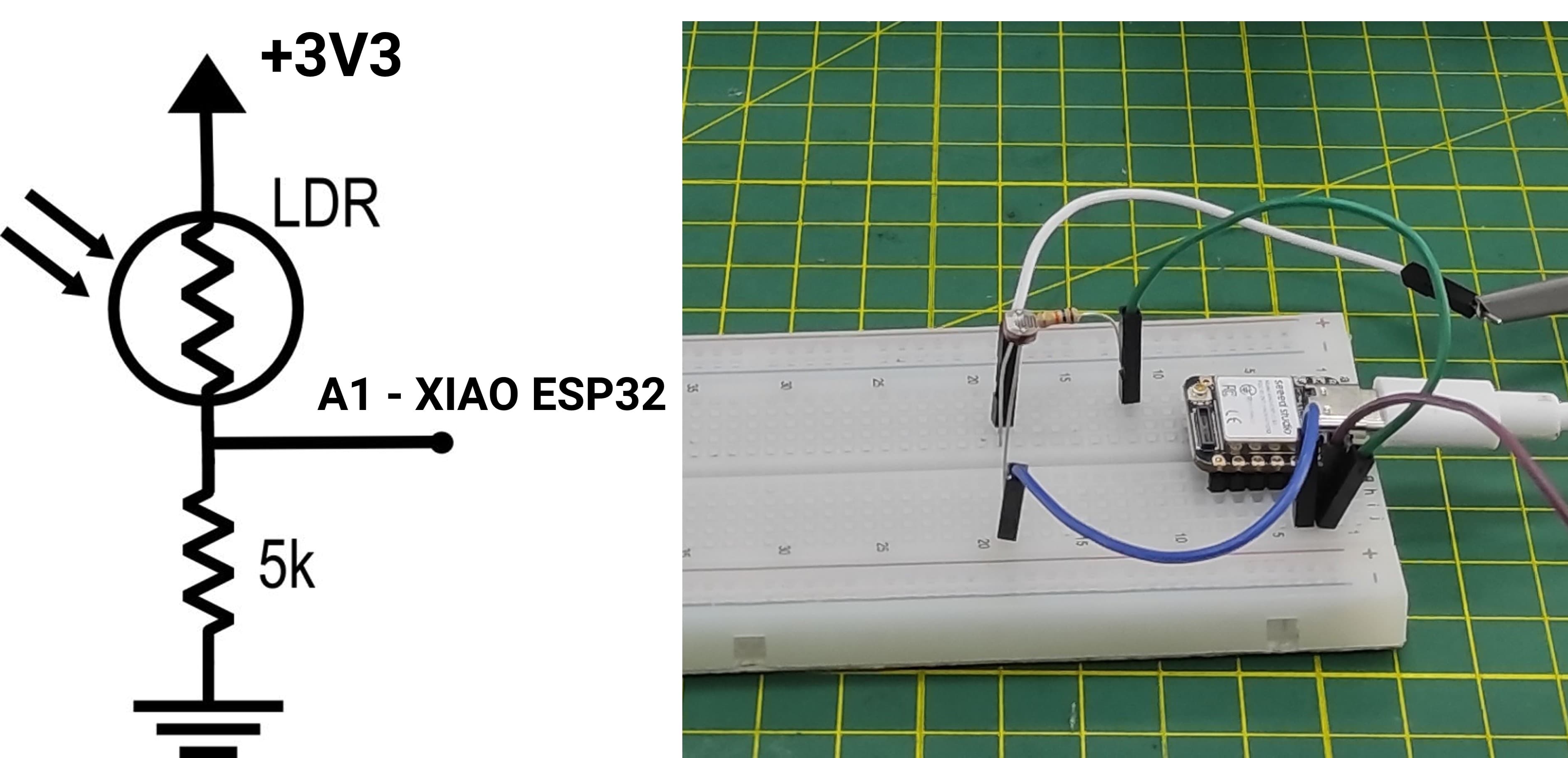
To better observe its operation, I connected an LDR photoresistor and monitored the signal using an oscilloscope.
Next, the LDR is connected to the XIAO microcontroller, and the measured values are monitored using the Serial Monitor.
How the code works- XIAO ESP32S3 - LDR SensorThis code reads the light intensity using an LDR (light-dependent resistor) connected to an analog pin of a XIAO ESP32-S3. In the setup, it initializes serial communication and configures the ADC resolution to 12 bits, allowing readings from 0 to 4095. In the loop, it continuously reads the analog value from the LDR, converts that value into a voltage (based on a 3.3V reference), and maps it into a percentage representing light intensity. Finally, it prints the raw value, calculated voltage, and light percentage to the Serial Monitor every 500 milliseconds.
            // Generated with ChatGPT (OpenAI)
            // Prompt:
            // Arduino code for XIAO ESP32-S3 to read an LDR on A0 and display ADC value, voltage, and light percentage via Serial.

            #define LDR_PIN A0

            // Variables para almacenar lecturas
            int rawValue = 0;
            float voltage = 0.0;
            int lightPercent = 0;

            void setup() {
                Serial.begin(115200);
                analogReadResolution(12);

                Serial.println("=== Sensor LDR en XIAO ESP32-S3 ===");
                delay(1000);
            }

            void loop() {

                // Leer valor analógico
                rawValue = analogRead(LDR_PIN);

                // Convertir a voltaje
                voltage = (rawValue / 4095.0) * 3.3;

                // Convertir a porcentaje de luz
                lightPercent = map(rawValue, 0, 4095, 0, 100);

                // Mostrar resultados en el Serial Monitor
                Serial.print("Valor crudo ADC: ");
                Serial.print(rawValue);
                Serial.print(" | Voltaje: ");
                Serial.print(voltage, 2);
                Serial.print(" V | Luz: ");
                Serial.print(lightPercent);
                Serial.println("%");

                delay(500);
            }
When observing the signal on the oscilloscope, the displayed voltage changes depending on the light intensity received by the LDR. As the light increases, the resistance of the LDR decreases, which causes a change in the output voltage of the circuit. This variation appears on the oscilloscope as a rising or falling voltage level. When the light level changes quickly (for example, by covering or uncovering the sensor), the oscilloscope shows corresponding transitions in the signal, allowing the response of the circuit to be visualized in real time.
- More light → lower LDR resistance → voltage changes (depending on circuit configuration).
- Less light → higher resistance → different voltage level.
1.2 Testing a RGB Led
An RGB LED is a light-emitting diode that contains three individual LEDs inside a single package: red, green, and blue. By controlling the intensity of each of these three colors, the device can produce a wide range of different colors through a process called additive color mixing.
Connections to the microcontroller:
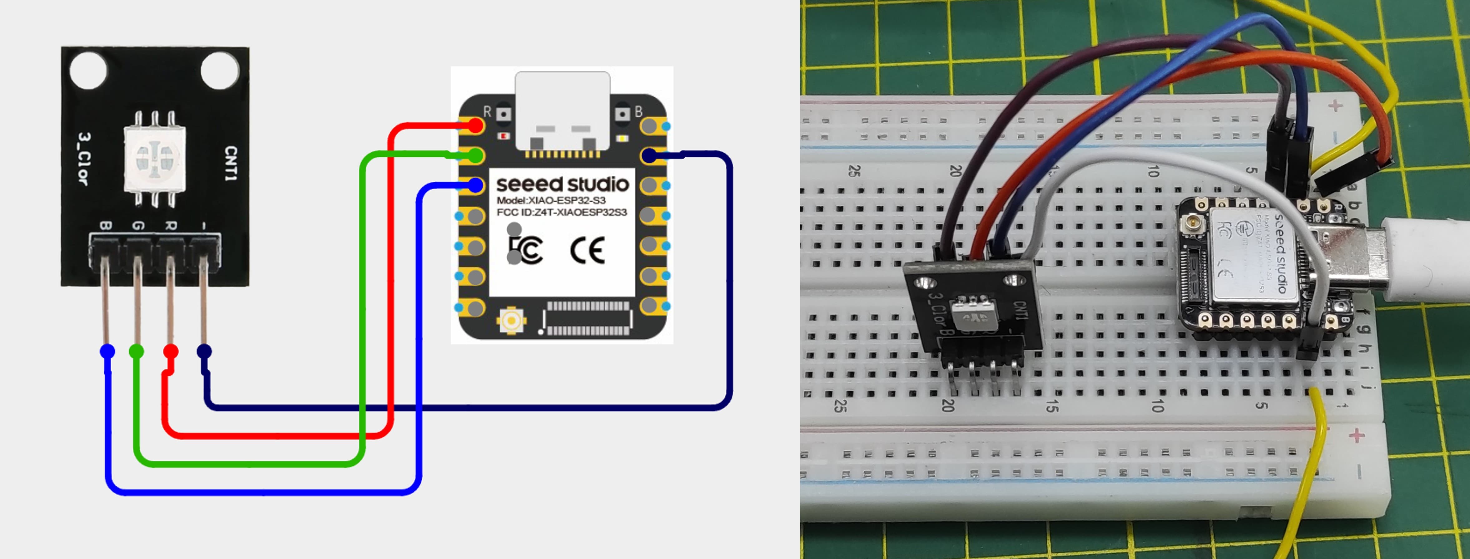
Think of an RGB LED as three separate tiny LEDs (Red, Green, and Blue) housed in a single package. By controlling the brightness of each of these three internal LEDs independently, you can mix them to create virtually any color.
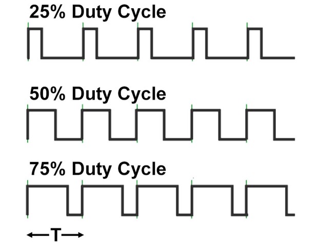
What is PWM and Why Do We Need It?
Microcontrollers are digital devices. They can only output two voltages on their pins: HIGH (e.g., 5V or 3.3V) or LOW (0V). This would normally mean you could only turn an LED completely on or completely off. PWM (Pulse Width Modulation) is the trick we use to simulate an analog voltage output. Instead of just turning the LED on and leaving it on, the microcontroller turns the LED on and off extremely fast (hundreds of times per second).
Duty cycle values – from off to full brightness
|
 |
Connecting with a multimeter
I created a program that turns on the green component of the RGB LED and allows it to operate at two different brightness levels.
How the Code works - XIAO ESP32S3 - LED RGB
This code controls an RGB LED by varying only the green channel (D1) using PWM. The red and blue channels remain off, while the program cycles through different brightness levels of green (low to maximum) and prints each state to the Serial Monitor, updating every 2 seconds..
// Generated with ChatGPT (OpenAI)
// Prompt:
// Arduino code for a XIAO ESP32-S3 with an RGB LED on pins D0, D1, and D2. Keep red and blue off, vary only the green LED brightness using PWM values 50, 128, 200, 255, and 0, display the current level in the Serial Monitor, and change every 2 seconds.

            // LED RGB - Solo D1 con valores específicos

            #define PIN_ROJO   D0
            #define PIN_VERDE  D1
            #define PIN_AZUL   D2

            void setup() {
                Serial.begin(115200);

                // ROJO y AZUL siempre apagados
                analogWrite(PIN_ROJO, 0);
                analogWrite(PIN_AZUL, 0);
            }

            void loop() {

                // Verde bajo
                analogWrite(PIN_AZUL, 0);
                analogWrite(PIN_ROJO, 0);
                analogWrite(PIN_VERDE, 50);
                Serial.println("Verde bajo (50)");
                delay(2000);

                // Verde medio
                analogWrite(PIN_AZUL, 0);
                analogWrite(PIN_ROJO, 0);
                analogWrite(PIN_VERDE, 128);
                Serial.println("Verde medio (128)");
                delay(2000);

                // Verde alto
                analogWrite(PIN_AZUL, 0);
                analogWrite(PIN_ROJO, 0);
                analogWrite(PIN_VERDE, 200);
                Serial.println("Verde alto (200)");
                delay(2000);

                // Verde máximo
                analogWrite(PIN_AZUL, 0);
                analogWrite(PIN_ROJO, 0);
                analogWrite(PIN_VERDE, 255);
                Serial.println("Verde máximo (255)");
                delay(2000);

                // Verde apagado
                analogWrite(PIN_AZUL, 0);
                analogWrite(PIN_ROJO, 0);
                analogWrite(PIN_VERDE, 0);
                Serial.println("Verde apagado (0)");
                delay(2000);
            }
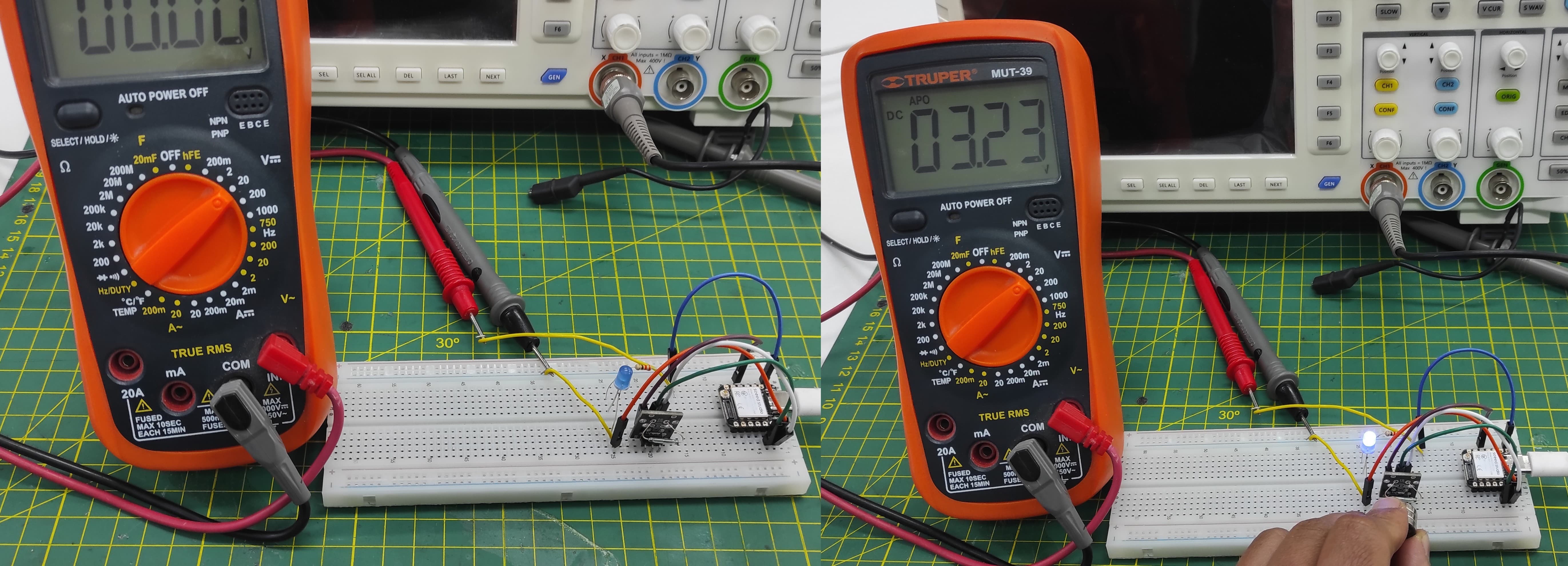
I connected the PWM signal to a multimeter to observe its behavior. The multimeter displayed an average voltage rather than the actual switching signal produced by the PWM. This occurs because the multimeter measures the mean value of the rapidly changing signal instead of capturing the individual pulses. As the duty cycle of the PWM changes, the measured voltage on the multimeter also changes proportionally. This experiment shows that while a multimeter can provide an approximate indication of the PWM level, it cannot display the real waveform, which is better observed using an oscilloscope.
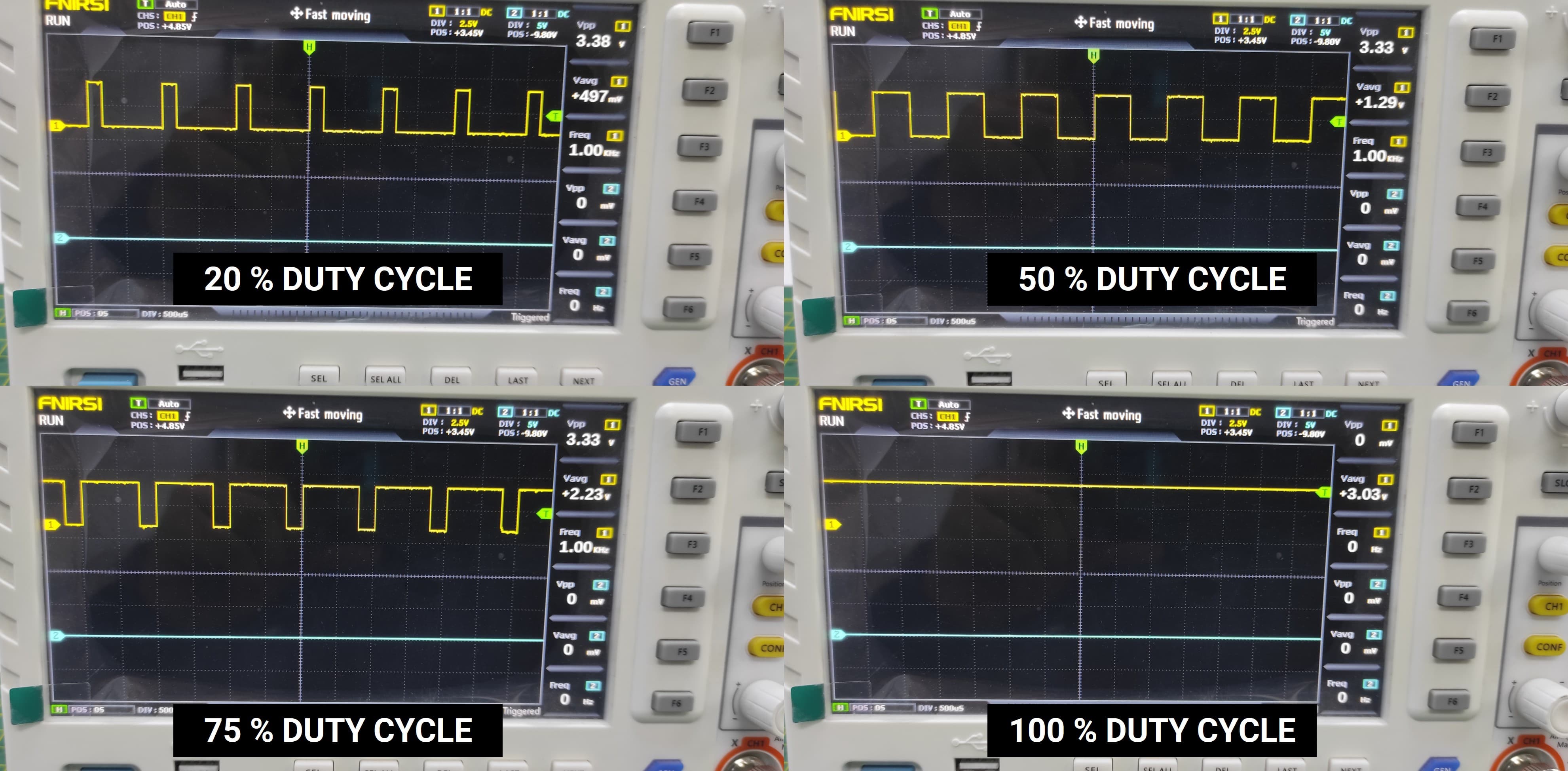
Connecting to an Oscilloscope
I connected the PWM signal to an oscilloscope to observe its waveform. On the oscilloscope, the signal appears as a series of square pulses that switch between a low voltage level and a high voltage level. By changing the PWM duty cycle, the width of the pulses changes while the frequency remains constant. A higher duty cycle results in wider pulses, meaning the signal stays at the high level for a longer time. This observation helps to clearly visualize how PWM controls the effective power delivered to a device such as an LED.
2. Testing an digital sensor
2.1 Reed Switch
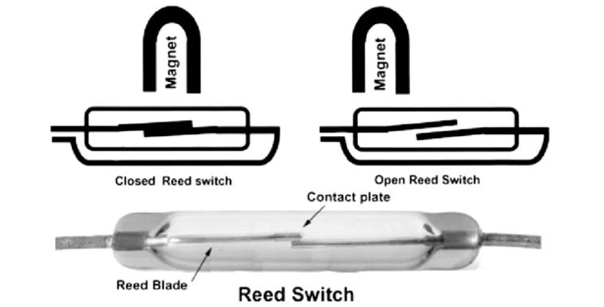
A reed switch is an electrical switch operated by a magnetic field, consisting of two ferromagnetic metal contacts (reeds) sealed within a small glass tube.
| Main Applications | Advantages | Disadvantages |
|---|---|---|
| Door/window sensors in security systems | ✅ Long lifespan (millions of cycles) | ❌ Contact bounce (requires debouncing) |
| Position sensors in industrial machinery | ✅ No power required to operate | ❌ Sensitive to external magnetic fields |
| Flow meters for water/gas | ✅ Hermetically sealed (dust/moisture resistant) | ❌ Glass can break under strong impact |
| Computer keyboards (older models) | ✅ Fast response time | |
| Speed sensors on bicycles | ✅ Very small and inexpensive | |
| Liquid level detectors |
I have connected a reed switch to pin D4 and an LED (with a resistor) to pin D0 on my XIAO ESP32-S3. The circuit is programmed so that when the reed switch is activated (by a magnet), the LED turns on.
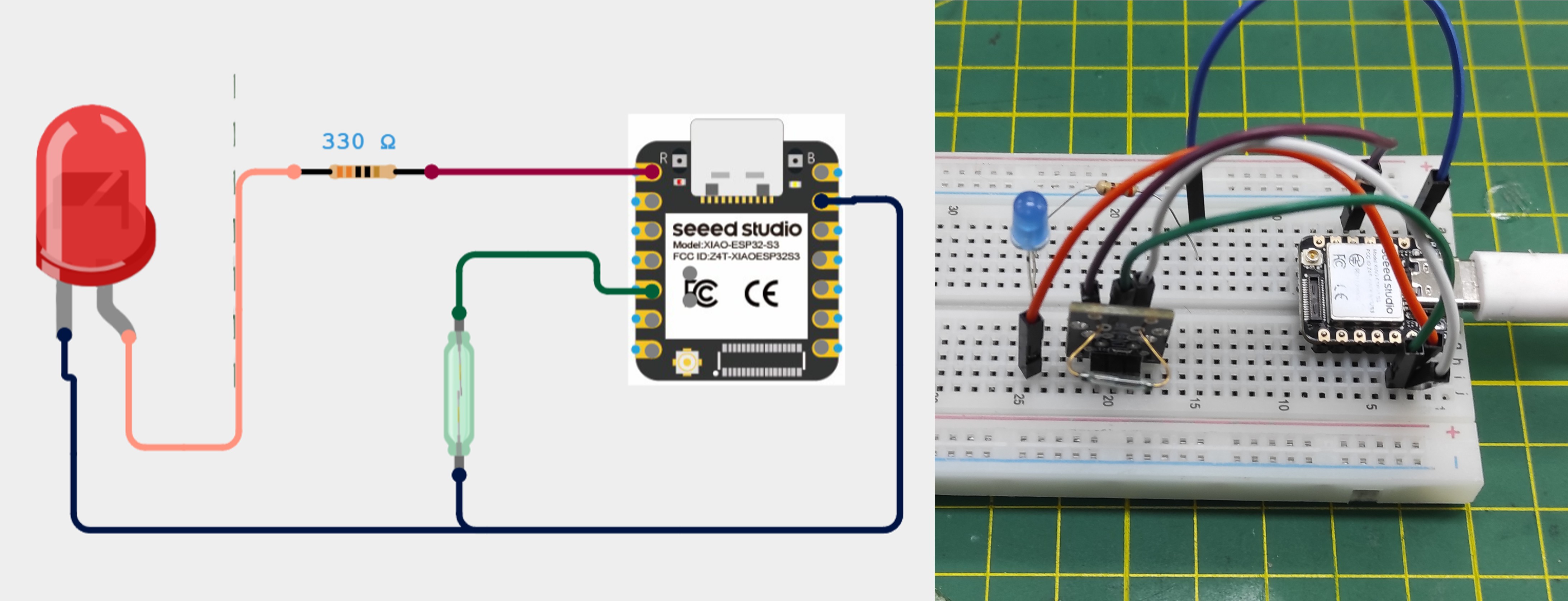
This code uses a reed switch (KY-021) to detect the presence of a magnet and control an LED. When the magnet is near, the sensor outputs LOW, turning the LED on; otherwise, the LED stays off. The loop continuously checks the sensor state and updates the LED accordingly.
// Generated with ChatGPT (OpenAI)
// Prompt:
// Arduino code for a XIAO ESP32-S3 using a KY-021 reed switch on pin D4 and an LED on pin D0. Turn the LED on when a magnet is detected and off when no magnet is present. Use the internal pull-up resistor and include a small delay for stable readings.

            // Código simple: LED en D0 se enciende cuando KY-021 detecta imán

            #define REED_PIN D4   // KY-021 conectado a D4
            #define LED_PIN D0    // LED con resistencia pull-down

            void setup() {
            pinMode(REED_PIN, INPUT_PULLUP);  // KY-021 con pull-up interno
            pinMode(LED_PIN, OUTPUT);         // LED como salida
            digitalWrite(LED_PIN, LOW);       // LED apagado al inicio
            }

            void loop() {
            if (digitalRead(REED_PIN) == LOW) {  // Si detecta imán
                digitalWrite(LED_PIN, HIGH);        // ENCIENDE LED
            } else {                              // Si no hay imán
                digitalWrite(LED_PIN, LOW);         // APAGA LED
            }
            delay(50);  // Pequeña pausa para estabilidad
            }
Individual Assignment
3. Working with Sensor and Microcontroller
For my individual assignment, I will measure the values from a joystick module using the custom PCB board that I designed and manufactured during Electronic Production week.
The joystick module (commonly the KY-023 model) is a two-axis analog input device (X and Y axes), similar to video game controllers, making it ideal for projects with Arduino or microcontrollers. It uses two potentiometers (10kΩ each) to detect position and has an integrated push button when pressed down.
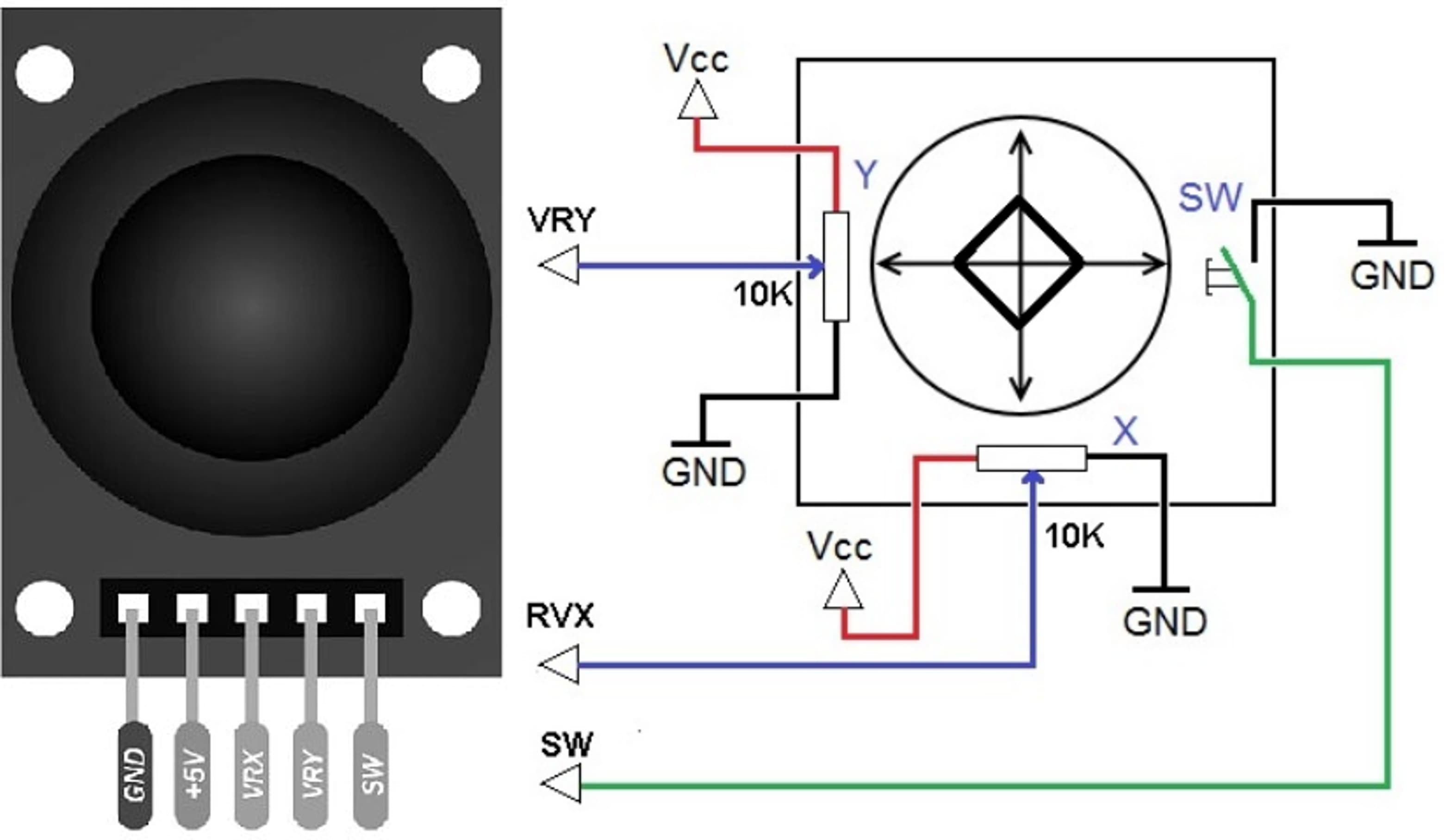
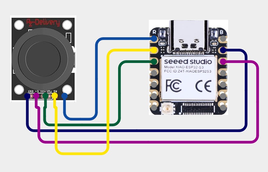
Connections with the Xiao ESP32 S3 Sense
This code reads a joystick connected to a XIAO ESP32-S3 without using external libraries. It captures the X and Y axis positions using analog inputs and reads the button state using a digital pin with an internal pull-up resistor. The values are then printed to the Serial Monitor in a simple CSV format, where the button is shown as 1 when pressed and 0 when released, updating every 100 milliseconds.
// Generated with ChatGPT (OpenAI)
// Prompt:
// Arduino code for a XIAO ESP32-S3 connected to a joystick with X and Y axes on pins D2 and D3, and a push button on D4. Read the analog axis values using 12-bit ADC resolution, read the button state using the internal pull-up resistor, and print the X value, Y value, and button status to the Serial Monitor in CSV format every 100 ms without using external libraries.

        // Joystick con XIAO ESP32-S3 - SIN LIBRERÍAS EXTERNAS
        // Solo usa funciones nativas

        // Definición de pines
        #define PIN_X    D2    // Eje X conectado a A0 (D0)
        #define PIN_Y    D3    // Eje Y conectado a A1 (D1)
        #define PIN_SW   D4    // Botón conectado a D2

        // Variables para almacenar lecturas
        int xValue = 0;
        int yValue = 0;
        int swValue = 0;

        // Para suavizado de lecturas (opcional)
        int xBuffer[5] = {0};
        int yBuffer[5] = {0};
        int bufferIndex = 0;

        void setup() {
        Serial.begin(115200);

        // Configurar resolución ADC a 12 bits (0-4095) - ESP32 específico
        analogReadResolution(12);

        // Configurar pin del botón con pull-up interno
        pinMode(PIN_SW, INPUT_PULLUP);

        Serial.println("=== Joystick en XIAO ESP32-S3 (SIN LIBRERÍAS) ===");
        Serial.println("X,Y,Boton");
        delay(500);
        }

        void loop() {
        // Leer valores analógicos directamente
        xValue = analogRead(PIN_X);
        yValue = analogRead(PIN_Y);

        // Leer botón (LOW = presionado por el pull-up)
        swValue = digitalRead(PIN_SW);

        // Opción 1: Mostrar valores crudos
        Serial.print(xValue);
        Serial.print(",");
        Serial.print(yValue);
        Serial.print(",");
        Serial.println(swValue == LOW ? "1" : "0");  // 1 = presionado, 0 = libre

        delay(100);
        }
Using the Arduino IDE Serial Monitor, I verified the joystick module functionality:
- X and Y axes: The analog values vary continuously as the joystick moves along each axis, reflecting the exact position - Push button: The digital reading shows:1 = Button pressed
0 = Button not pressed
This confirms that all three inputs (X, Y, and SW) are working correctly.
4. Learnings
PWM (Pulse Width Modulation) simulates analog output by quickly switching a digital signal between HIGH and LOW. The duty cycle—the percentage of time the signal is HIGH—determines the output level, from 0% (always off) to 100% (always on). This technique controls LED brightness or motor speed. On the ESP32, analogWrite() accepts values from 0 to 255, directly mapping to duty cycle percentage.
Analog sensors (LDR, potentiometer, joystick) provide continuous readings via analogRead(). ESP32 returns 12-bit values (0-4095). Most need a voltage divider circuit.
Digital sensors (buttons, reed switches) give only HIGH/LOW states. Use digitalRead() with pull-up resistors. INPUT_PULLUP enables internal resistors, avoiding floating readings.
4.1 Problems and How I fixed
When I was using the oscilloscope, I noticed a significant amount of noise in the waveform, which made it difficult to clearly analyze the signal. The graph appeared unstable and distorted, preventing accurate observations. To address this issue, I switched to shorter wires and ensured that all connections were firmly secured. These changes helped reduce interference and signal loss, resulting in a much cleaner and more stable waveform, which greatly improved the overall visualization and analysis.
5. Files
Here are the files available for download.