Documented how you made (milled, stuffed, soldered) the board
✓
Documented that your board is functional
✓
Explained any problems and how you fixed them
✓
Uploaded your source code
✓
Included a ‘hero shot’ of your board
Electronics Production
Group Assignment
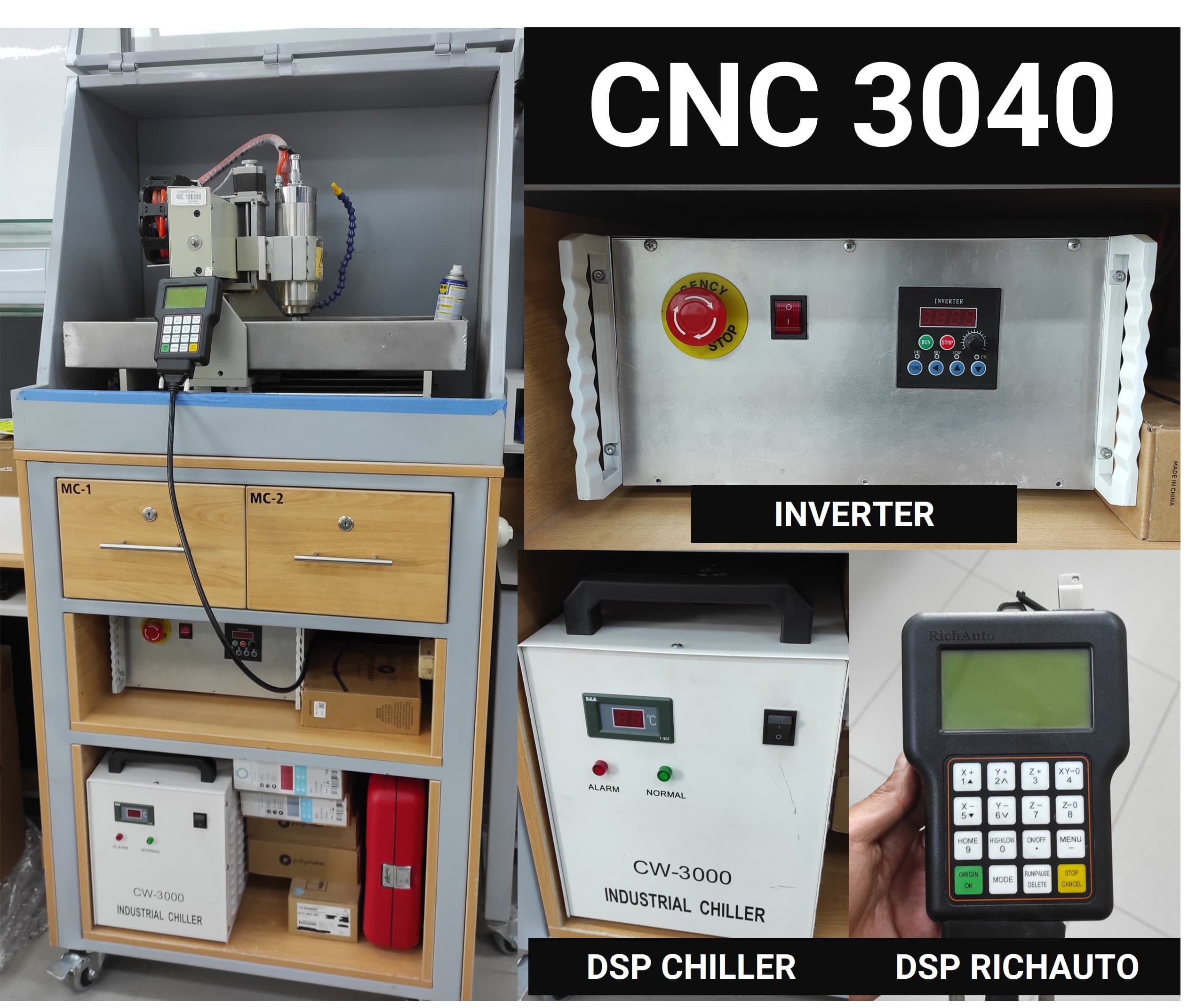
1. CNC Router - CNC3040
1.1 Specifications
The CNC3040 desktop CNC machine, with its advanced capabilities, allows the execution of various complex and detailed projects. Here are some examples that demonstrate its versatility and ability to adapt to a wide range of creative and industrial needs and applications.
Specification
Details
Brand
CNC ZONE
Model
CNC3040 Desktop small CNC Machine
Precision Ball Screw
1605
Effective Work Area
300 x 400 x 80 mm
XYZ Rail Material
Hard Chrome Shaft
XY Rail Diameter
20mm
Z Rail Diameter
16mm
XYZ Axis Torque
57*78 250 OZ/IN (2.2N/CM)
Repeat Positioning Accuracy
0.01 mm
Working Accuracy
0.02 mm
Processing Speed
0-4000 mm/min
A Axis Rotation Speed
0-180 rpm/min
Rear Door Material
Stainless Steel
Switched Mode Power Supply
Integrated 24V 350W
Spindle Power
2200W Water-Cooled Frequency Spindle
Spindle Inverter
2200w
Input Power
220V/110V Power Supply (5)
Output Current
Drive 4.5A (Peak 5A)
Drive Motor
57*42 Stepper Motors (4-wire Bipolar)
Net Weight
75 kg
Gross Weight
102 kg
Outer Packaging
67*78*71 (cm)
2. CNC Router - Milling Test
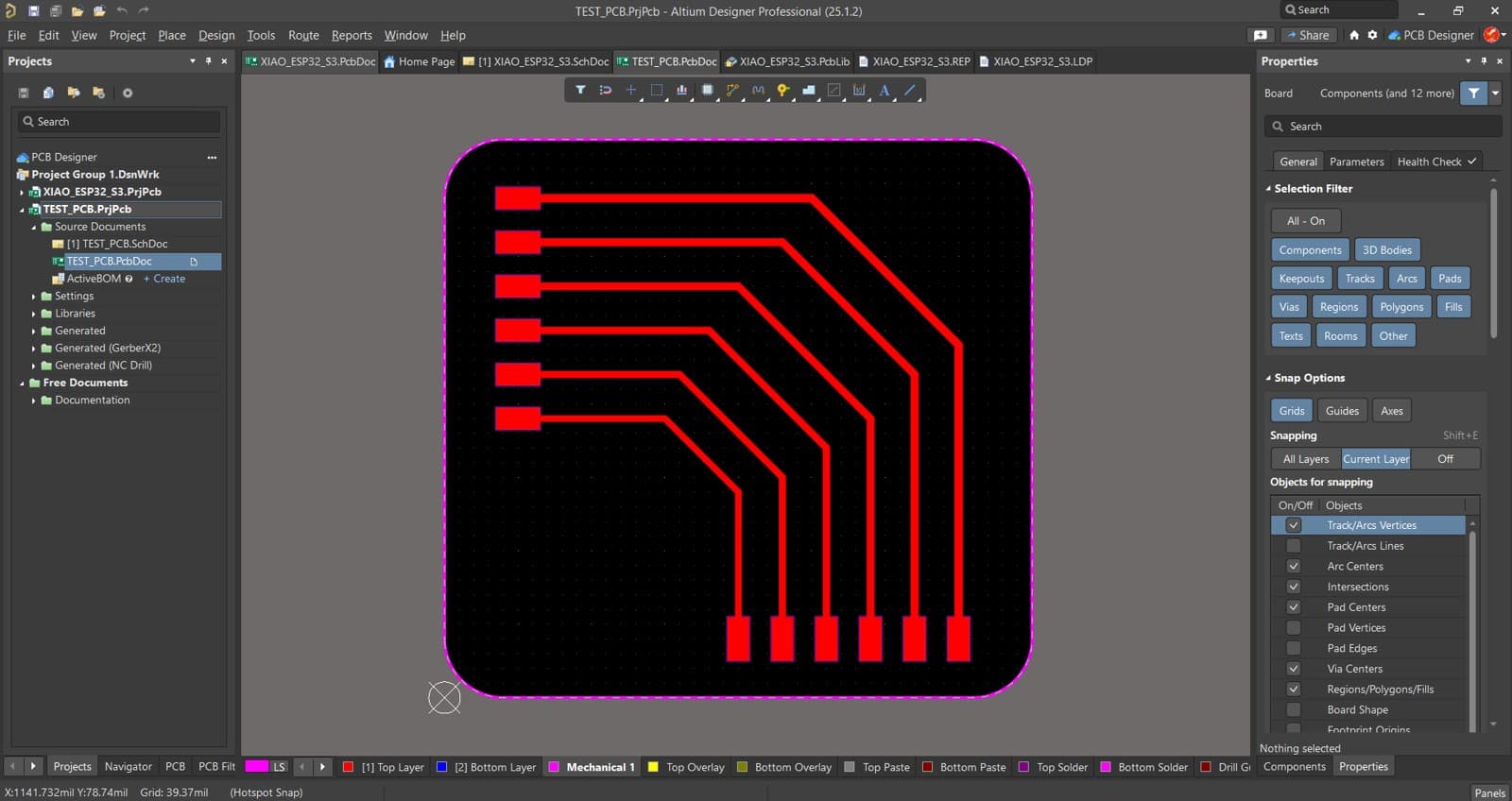
2.1 Preparing the PCB Milling Test File
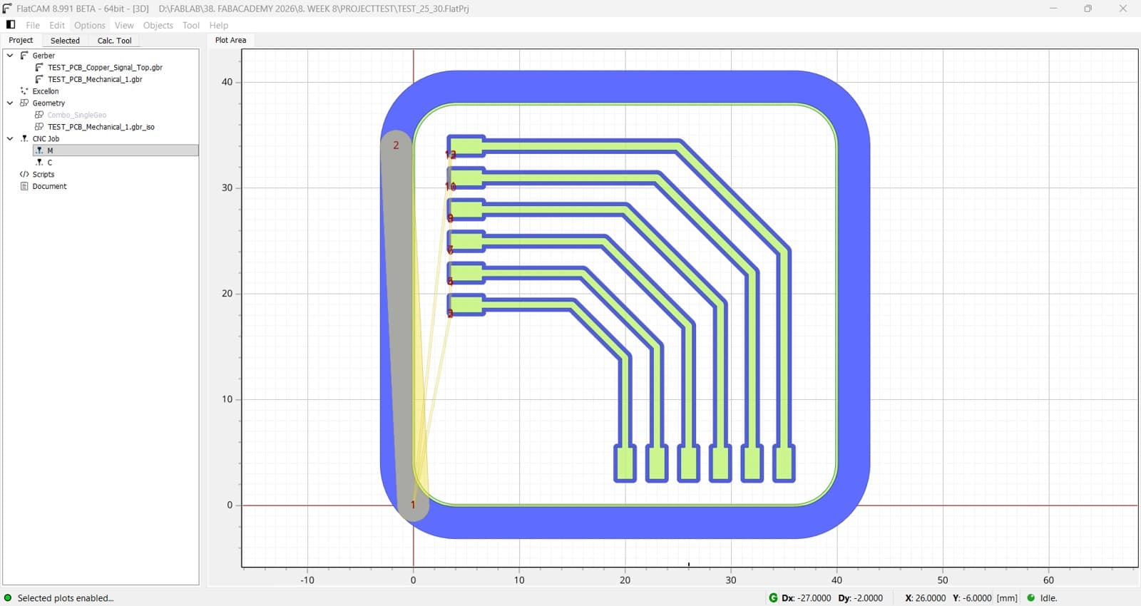
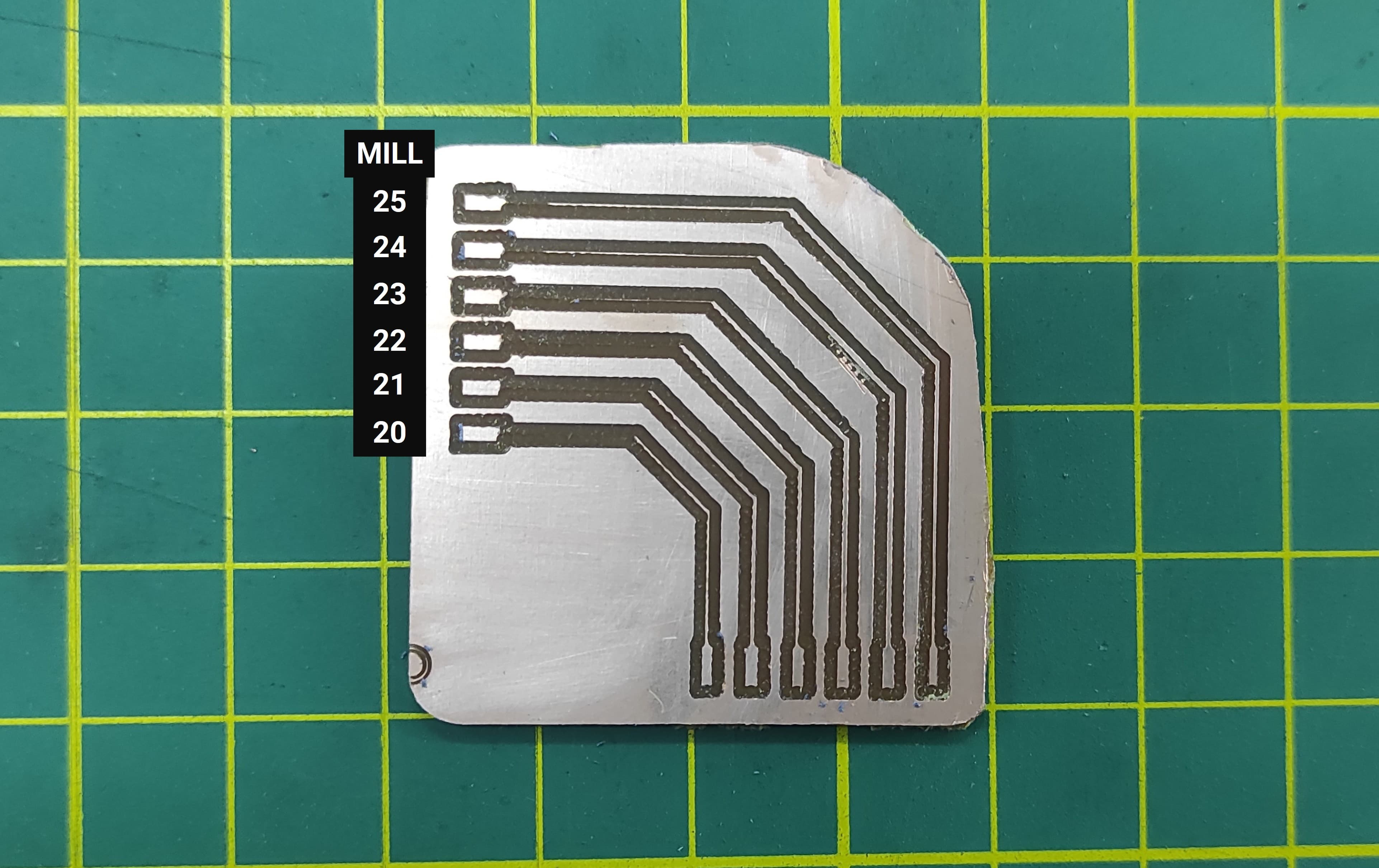
To test the milling performance of the CNC router for PCB fabrication, I created a test file with traces ranging from 20–25 mil and 25–30 mil. This test allows evaluation of the machine’s ability to accurately mill different trace widths.
2.2 Using FlatCAM for PCB Manufacturing
2.2.1 Generating G-code for Milling the PCB
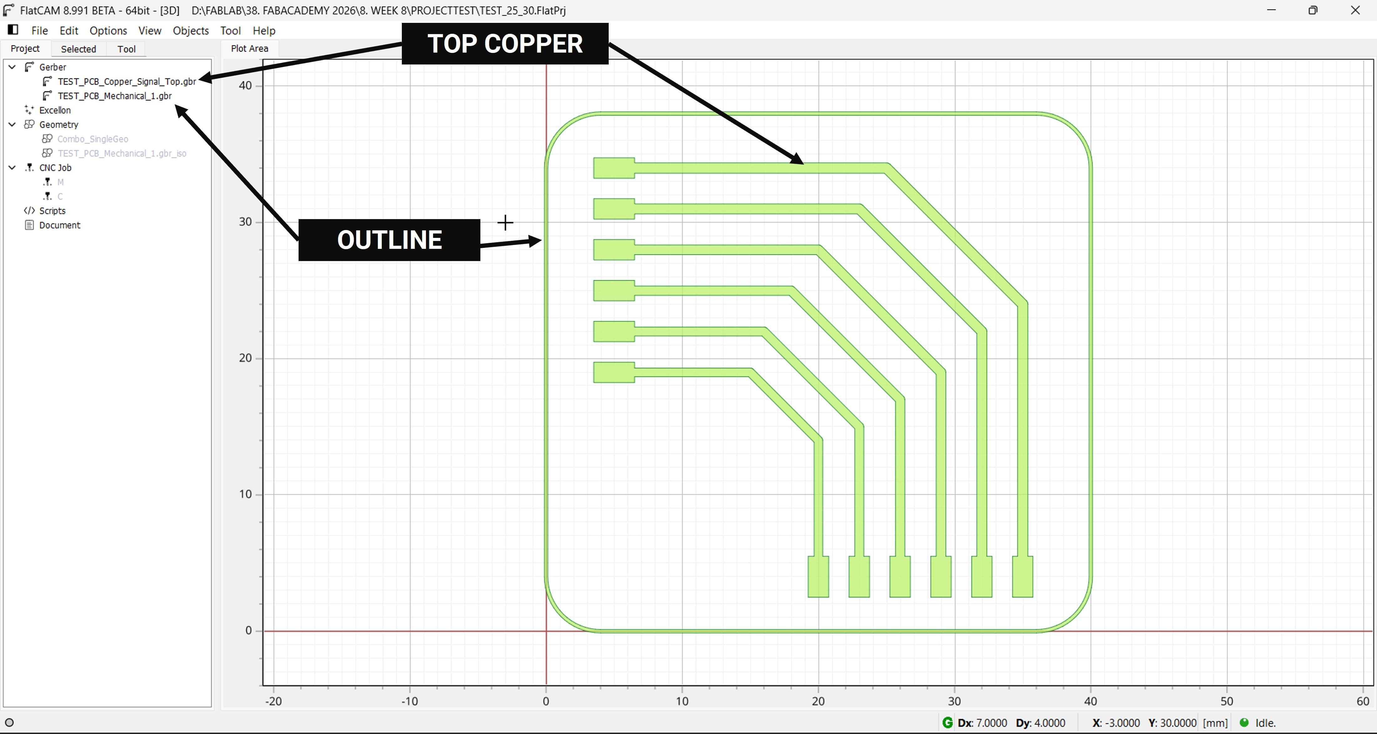
I decided to use FlatCAM to generate the G-code for milling and cutting the PCB.
First, we import the Gerber files corresponding to the Top Copper layer and the PCB outline.
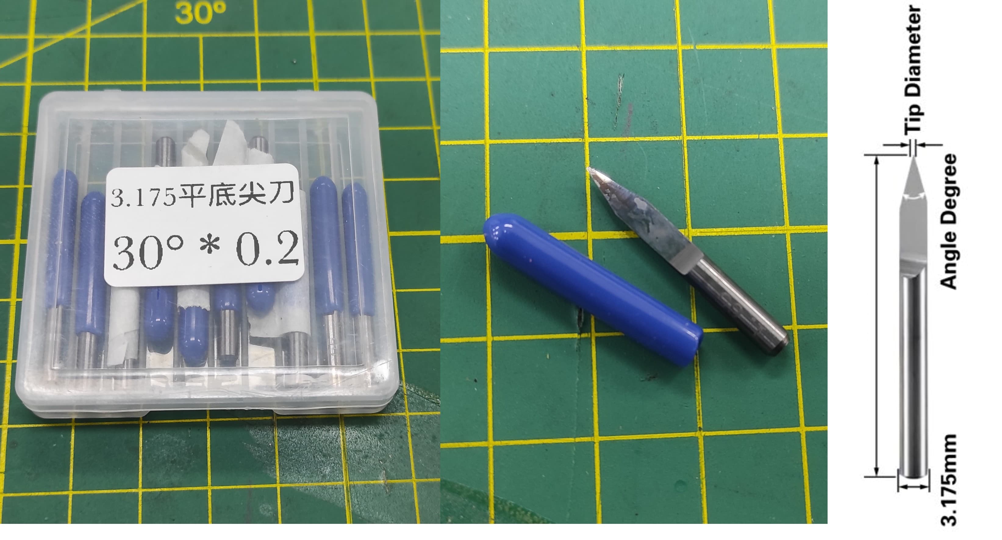
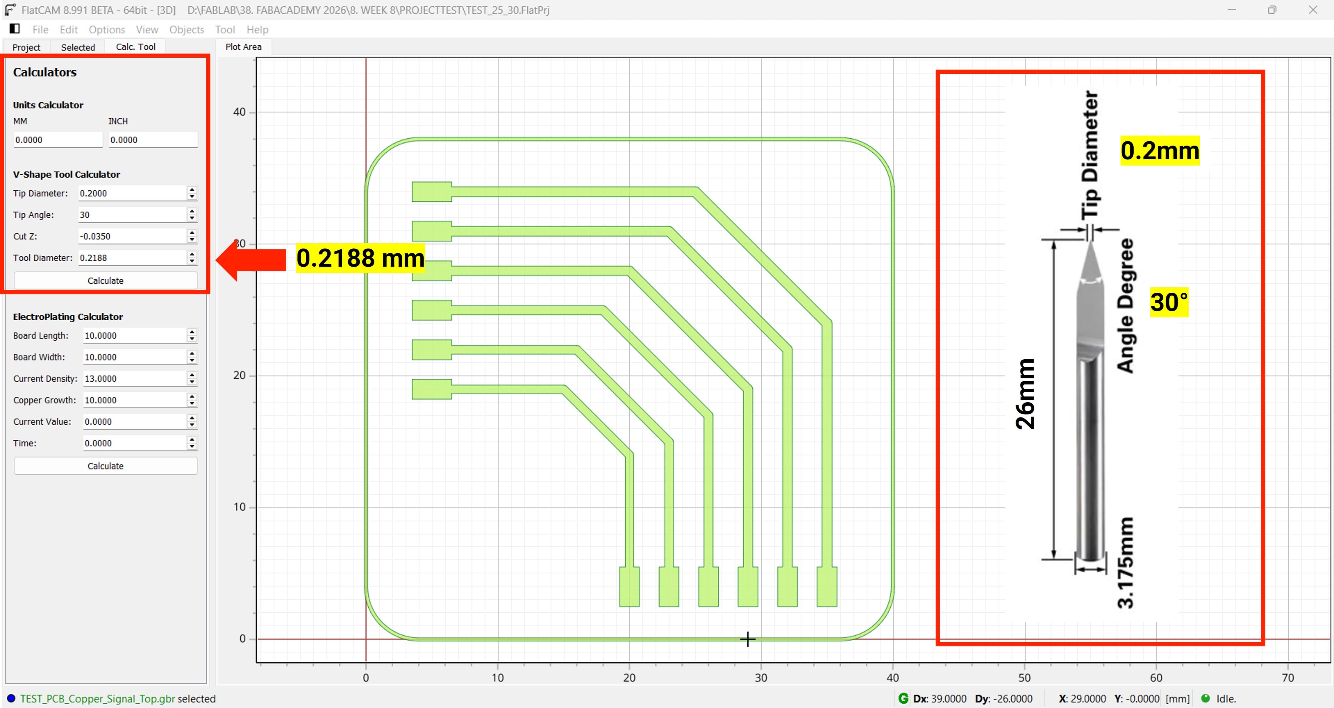
I am using a V-endmill for milling, with a 3.175 mm diameter, a 30° angle, lenght 26mm, and a 0.2 mm tip.
First, we need to calculate the effective tool diameter. For this, we use the calculator available in FlatCAM.
We can find the calculator in Tool Menu → Calculator.
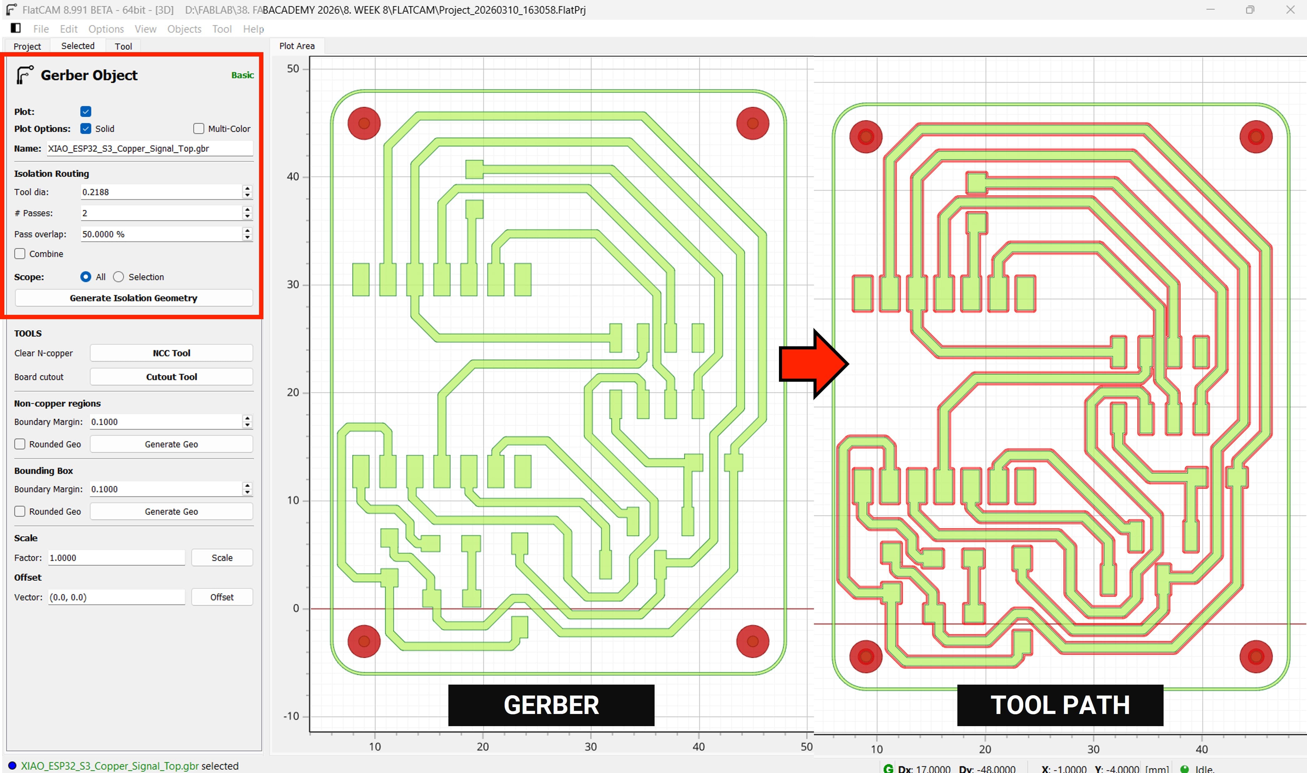
The result for our Tool Diameter is 0.2188 mm
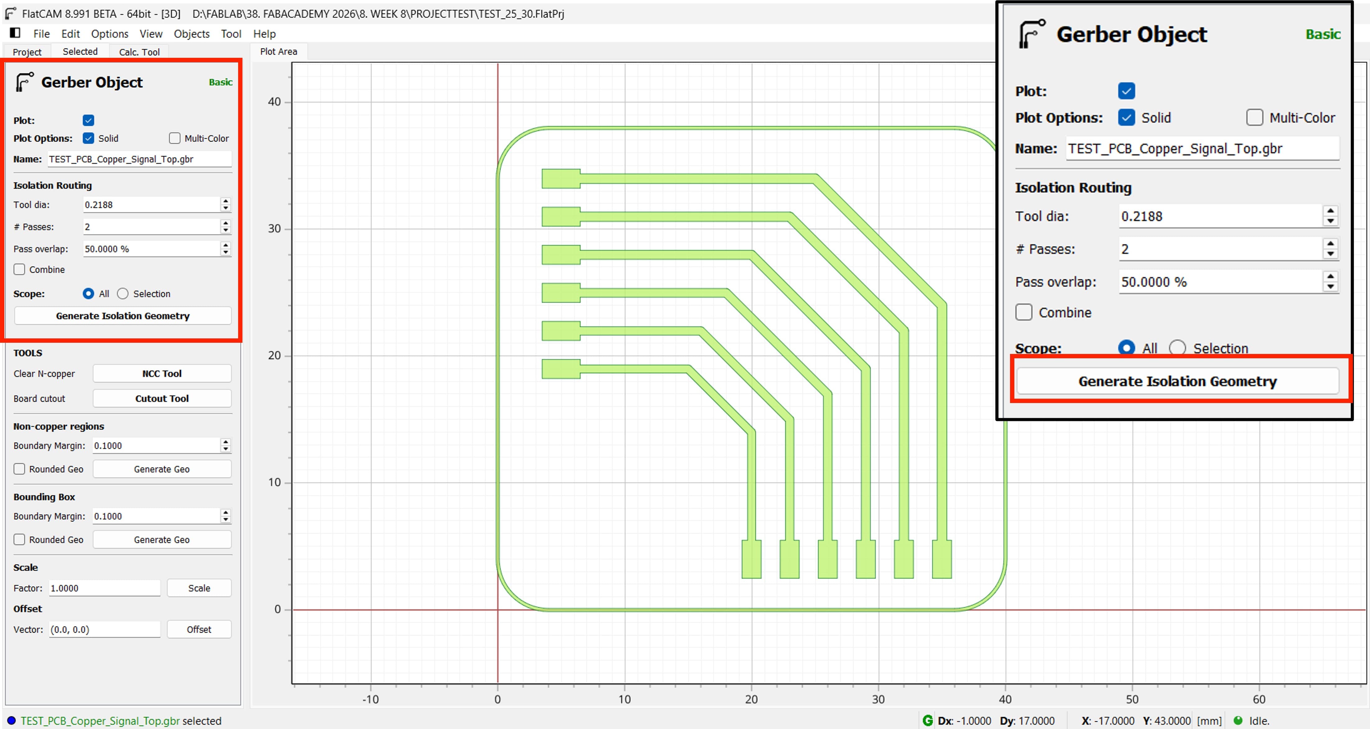
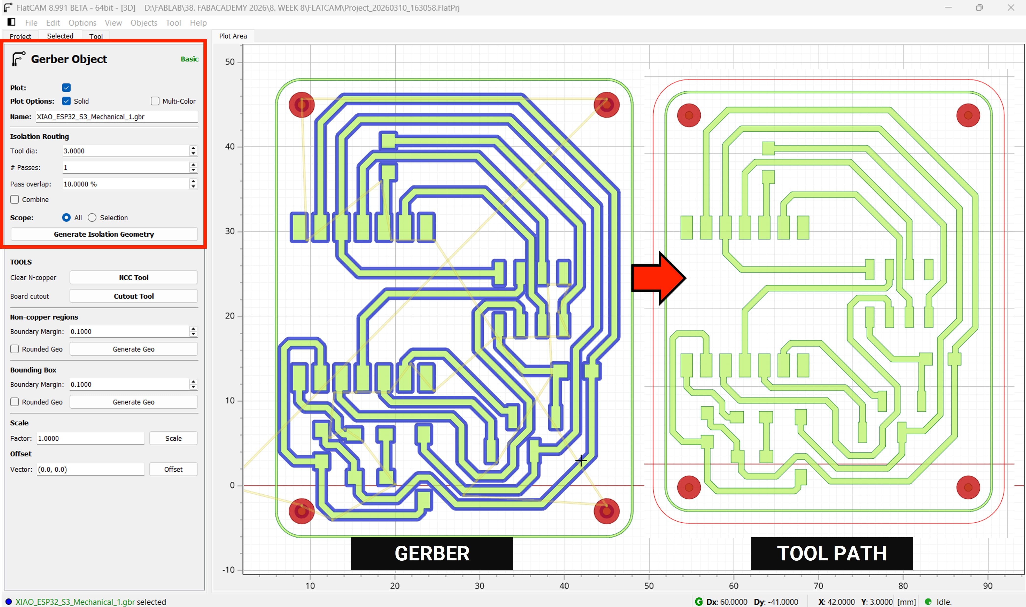
Next, we need to configure the milling settings. We will use the following parameters:
After clicking Generate Isolation Geometry in FlatCAM, the software creates the toolpaths used to isolate the PCB traces from the surrounding copper.
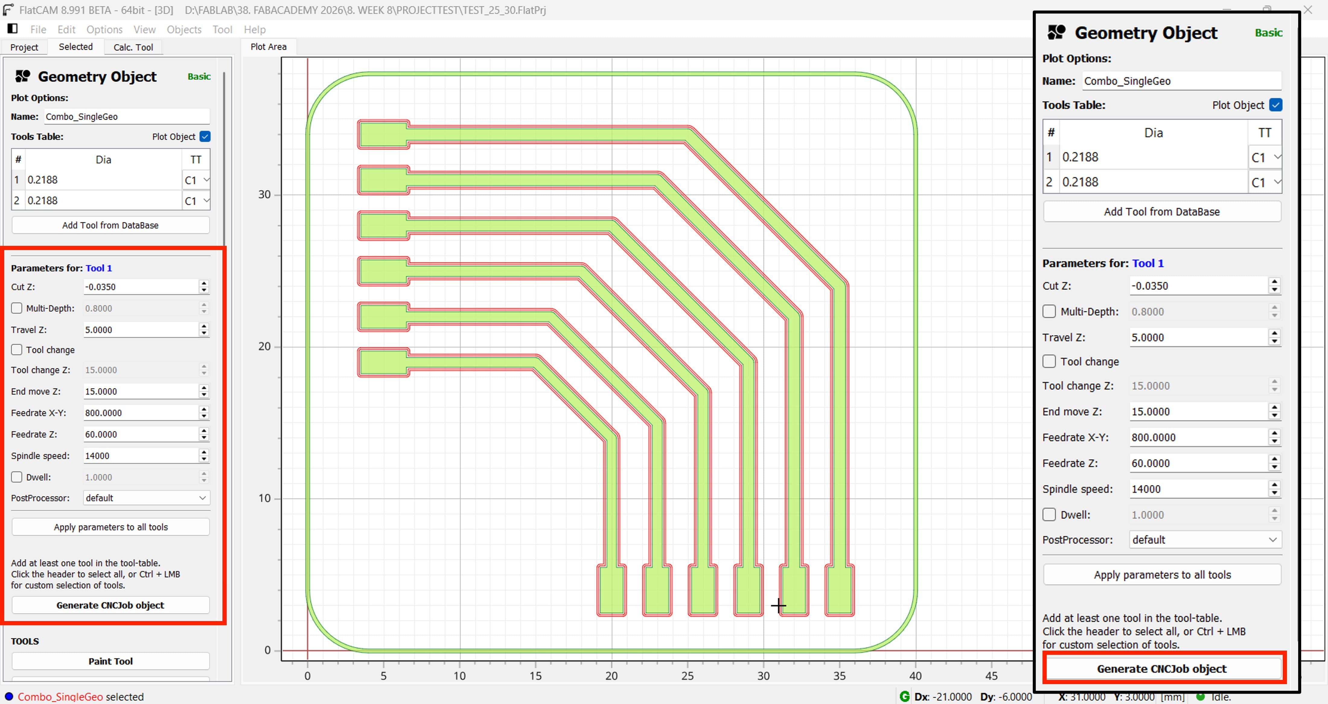
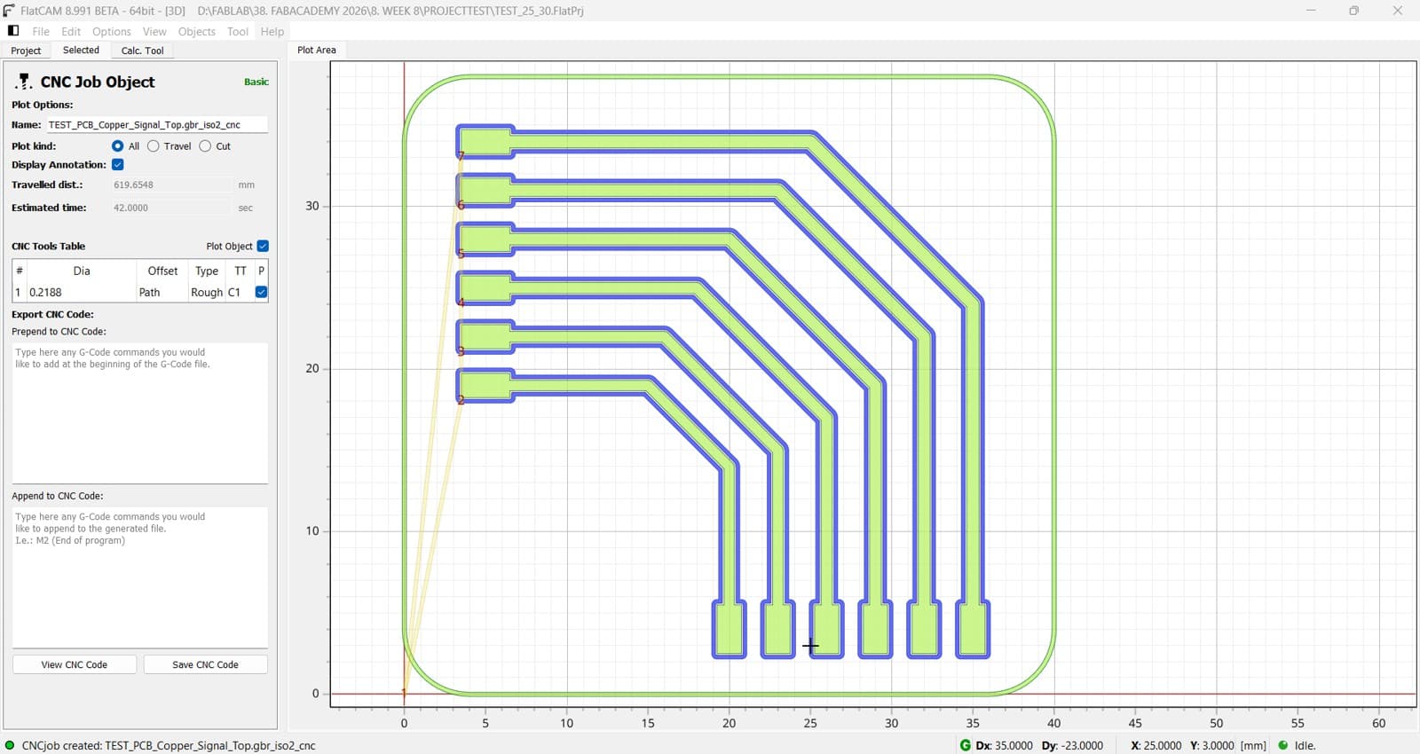
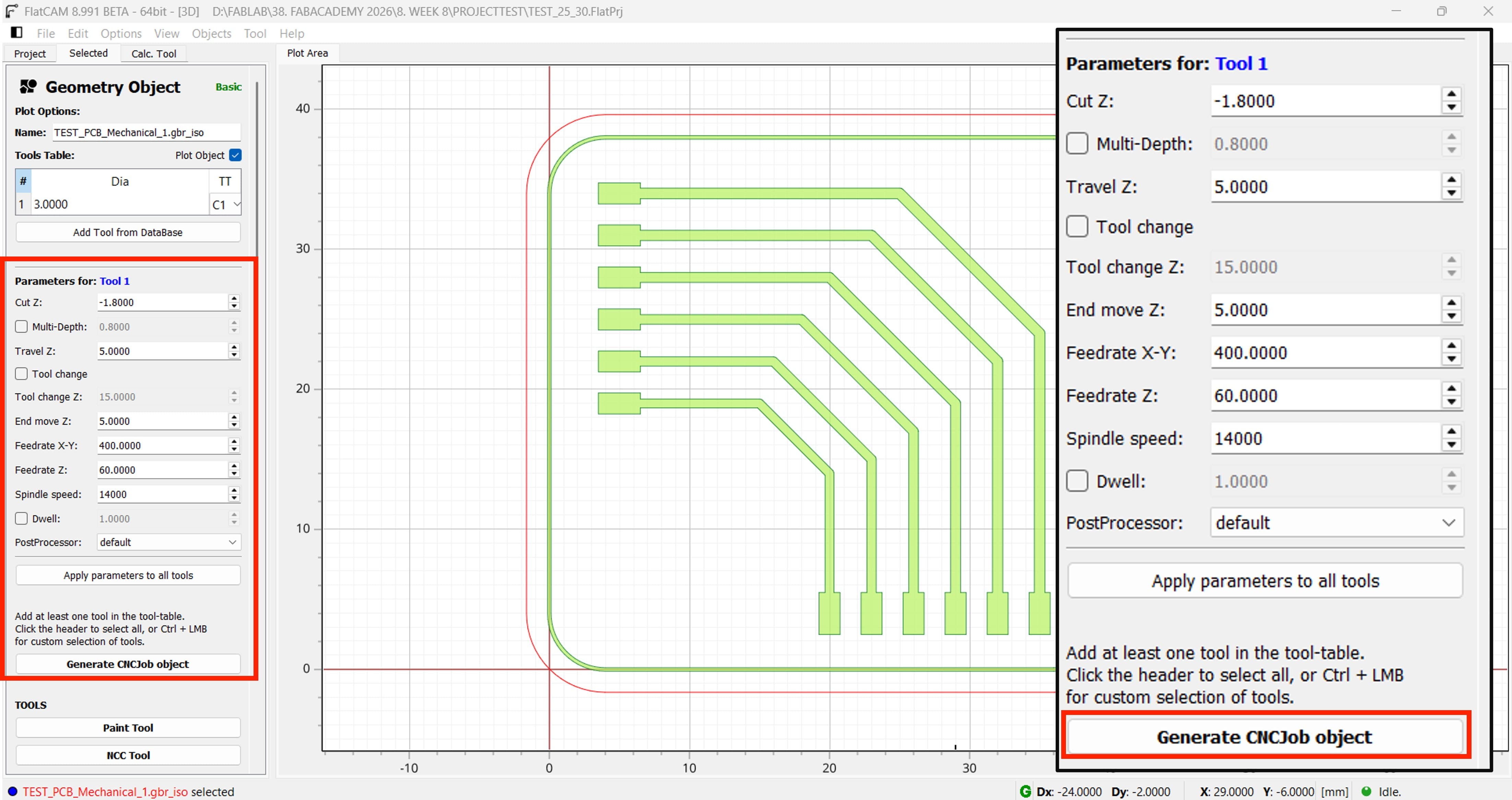
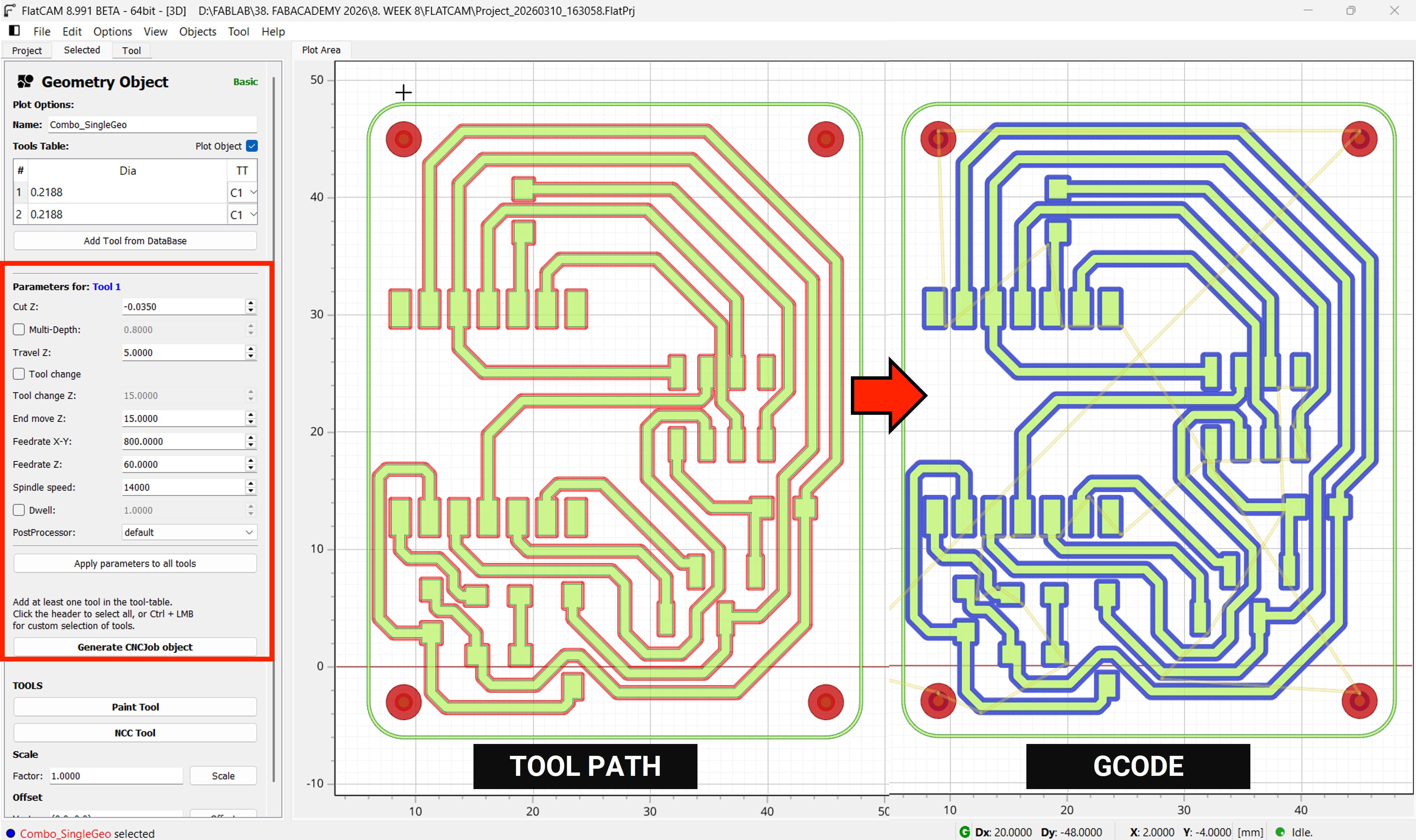
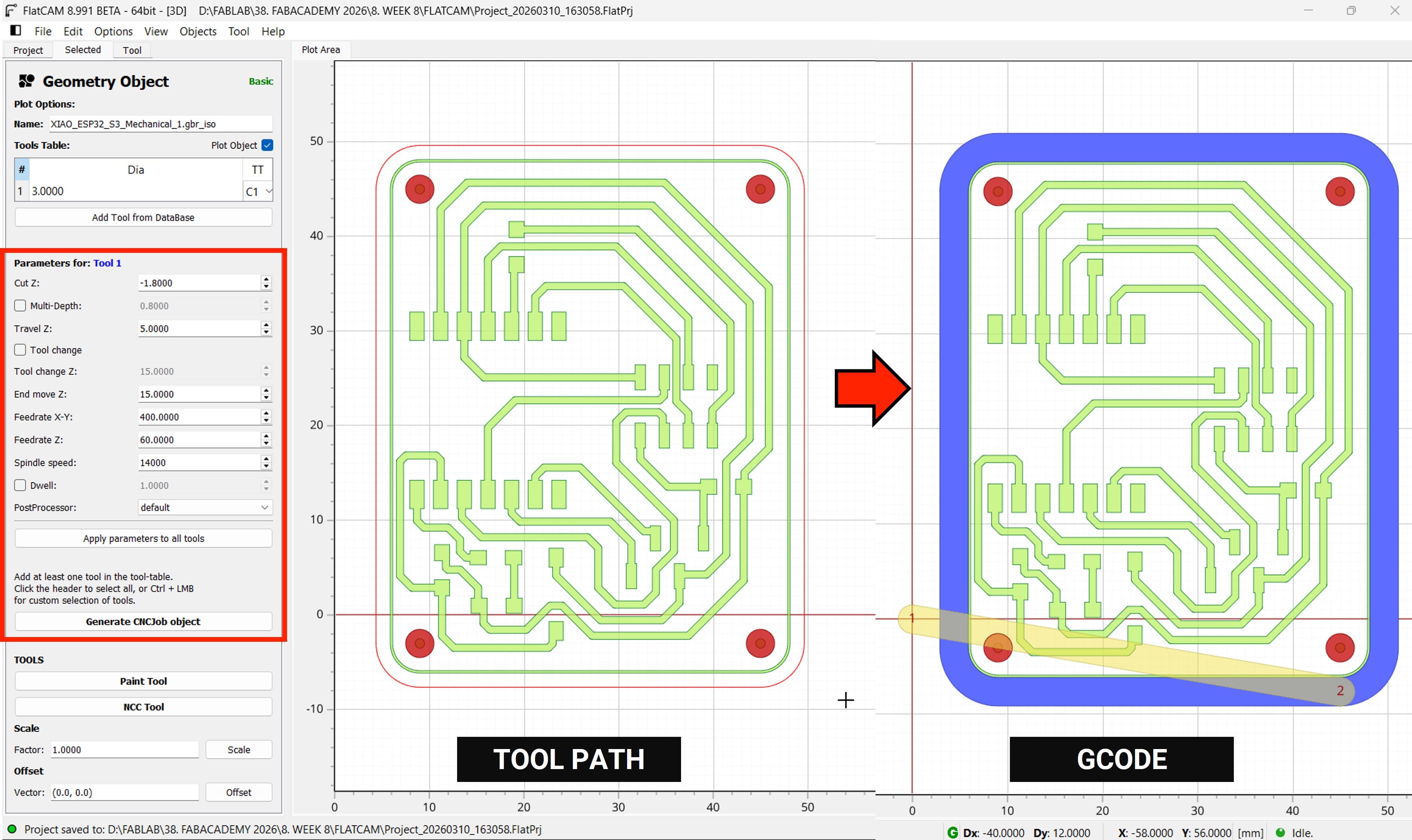
When you click Generate CNCJob Object in FlatCAM, the software converts the geometry toolpaths into machine instructions (G-code) that the CNC machine can execute.
2.2.2 Generating G-code for Cutting the PCB's outline
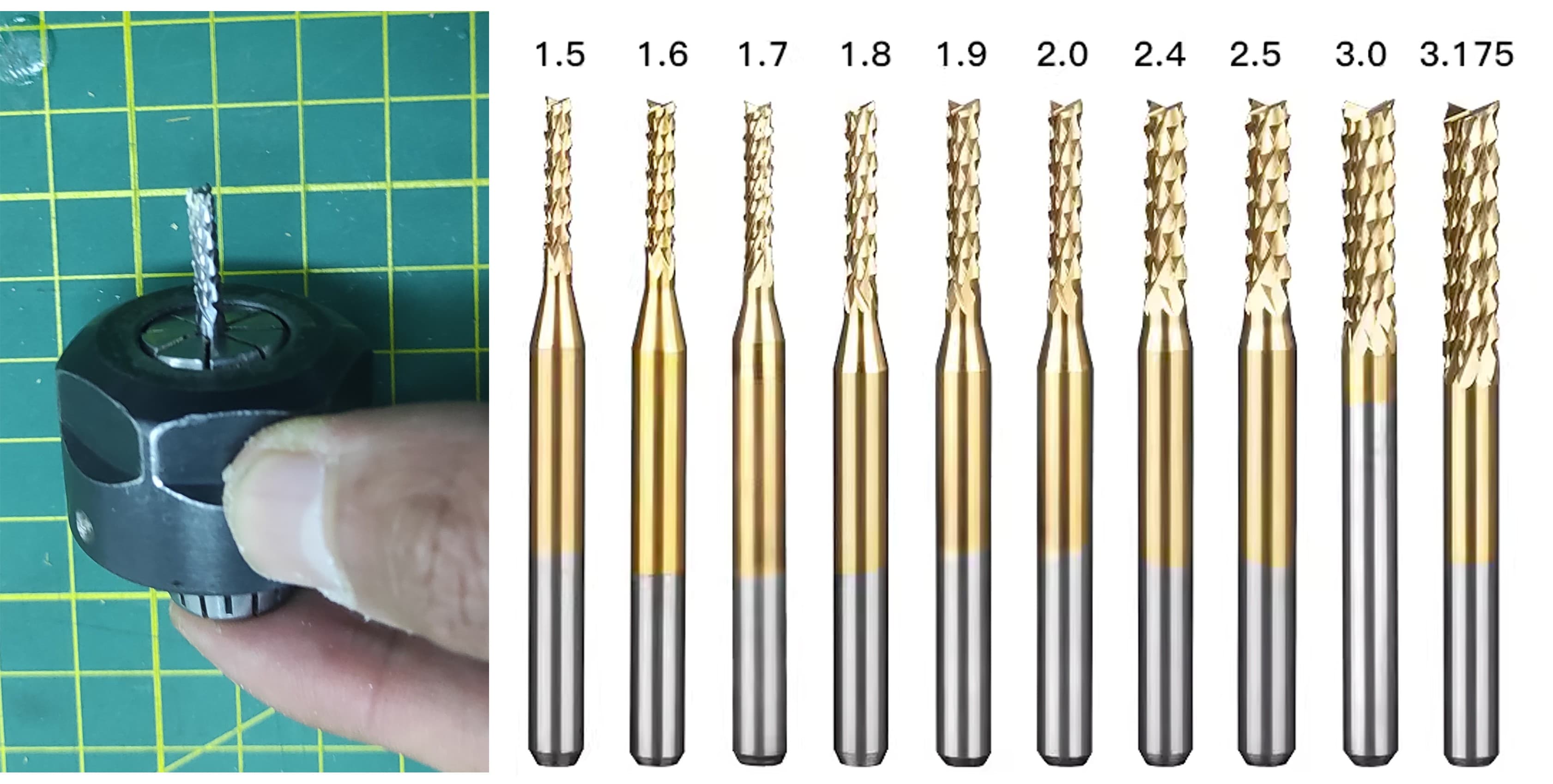
Now let's continue generating the G-code for cutting the outline. For that, I am going to use a 3 mm diameter corn end mill.
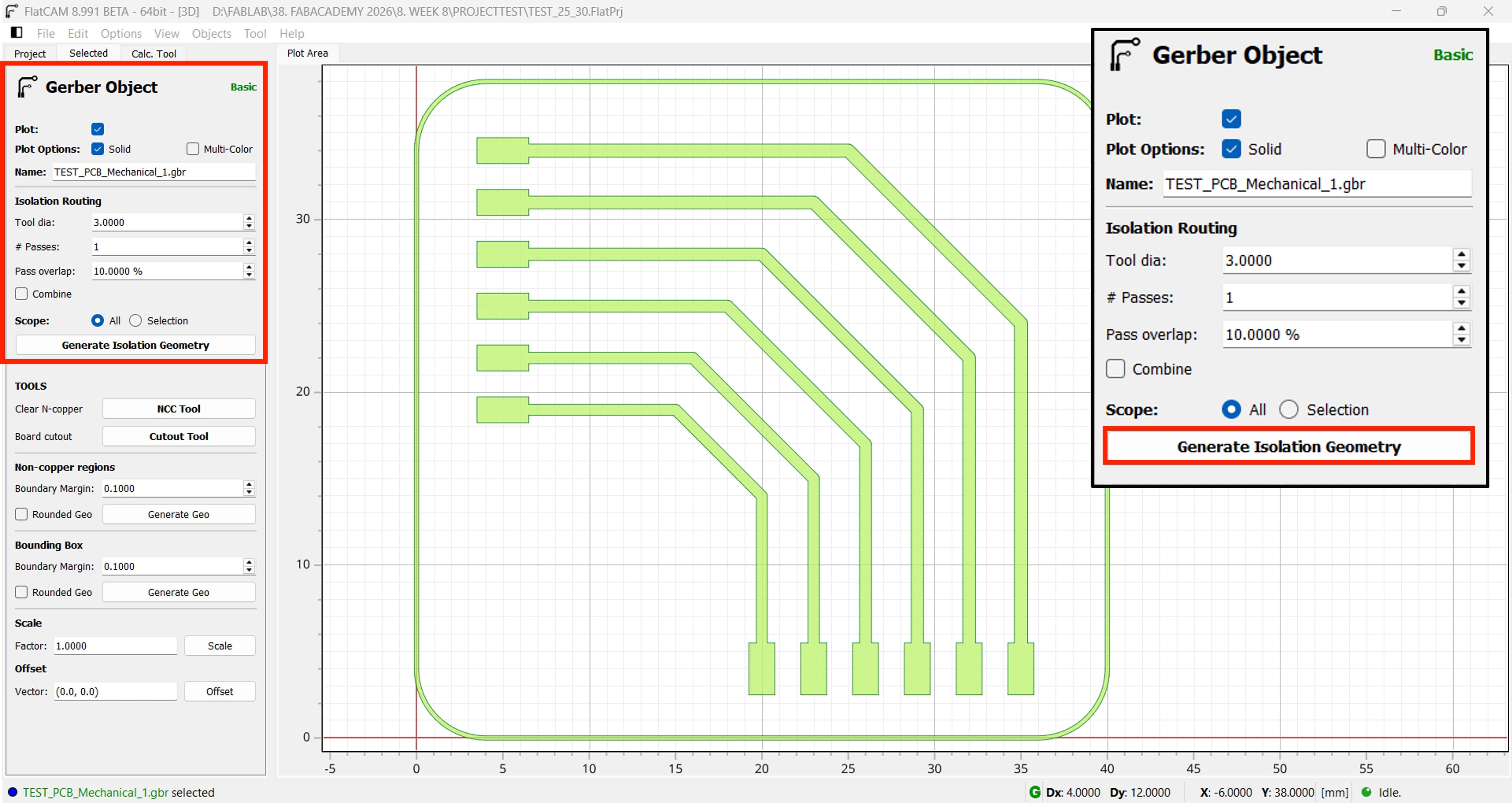
Now we need to work with the outline, so in the settings the most important parameter is the tool diameter, which is 3 mm.
After clicking Generate Isolation Geometry in FlatCAM, the software creates the toolpaths used to isolate the PCB traces from the surrounding copper.
When you click Generate CNCJob Object in FlatCAM, the software converts the geometry toolpaths into machine instructions (G-code) that the CNC machine can execute.
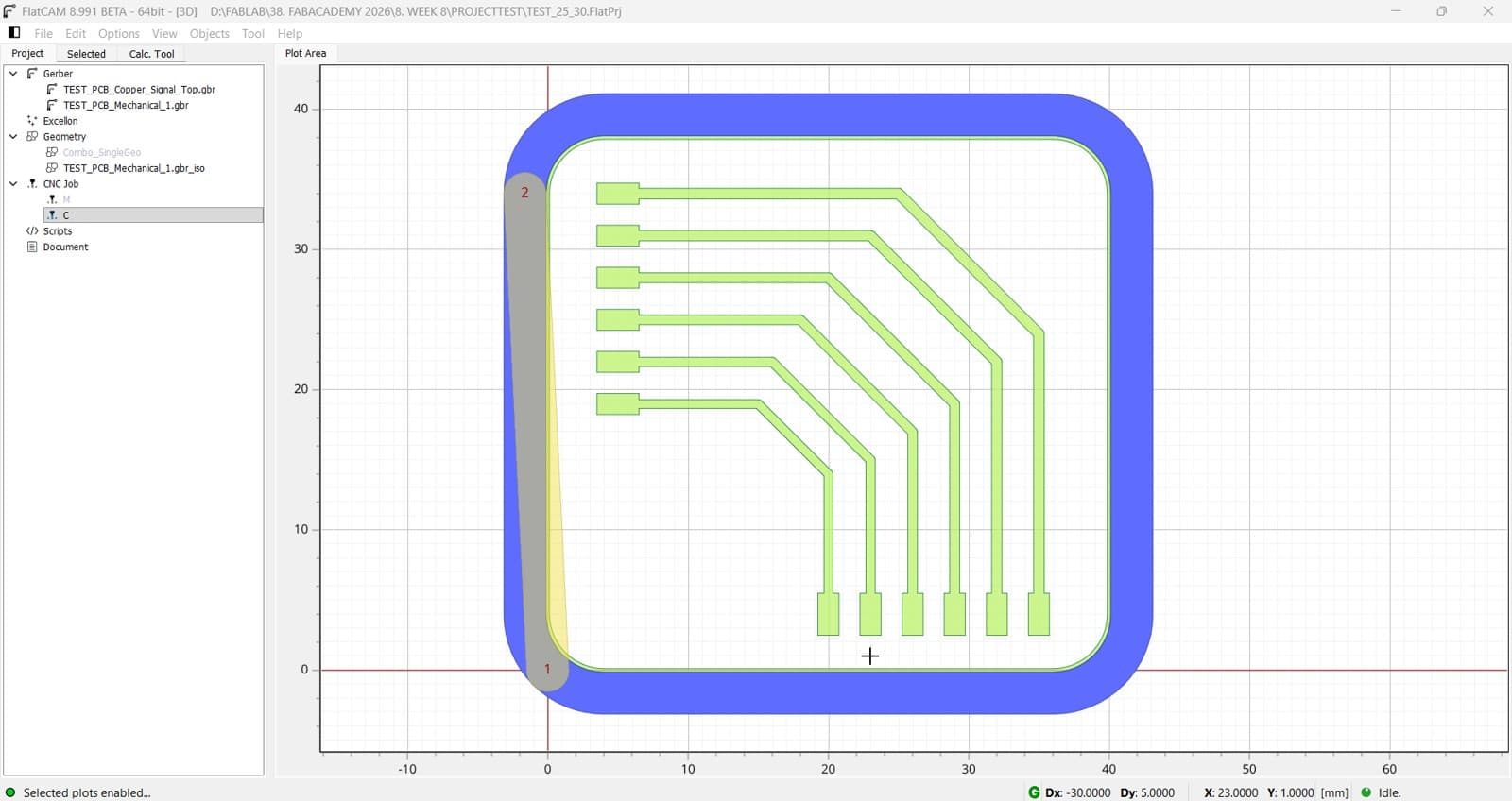
Now We have both Gcode for milling and cutting the PCB
3. Making the PCB
Now We are going to start making the PCB, so lets keep on mind the following parameters:
Parameter
Value
Spindle Speed
14,000 RPM
Feed X-Y
800 mm/min
Plunge Rate
60 mm/min
Tool
V-Endmill Tip 0.2mm 30°
Material
FR1
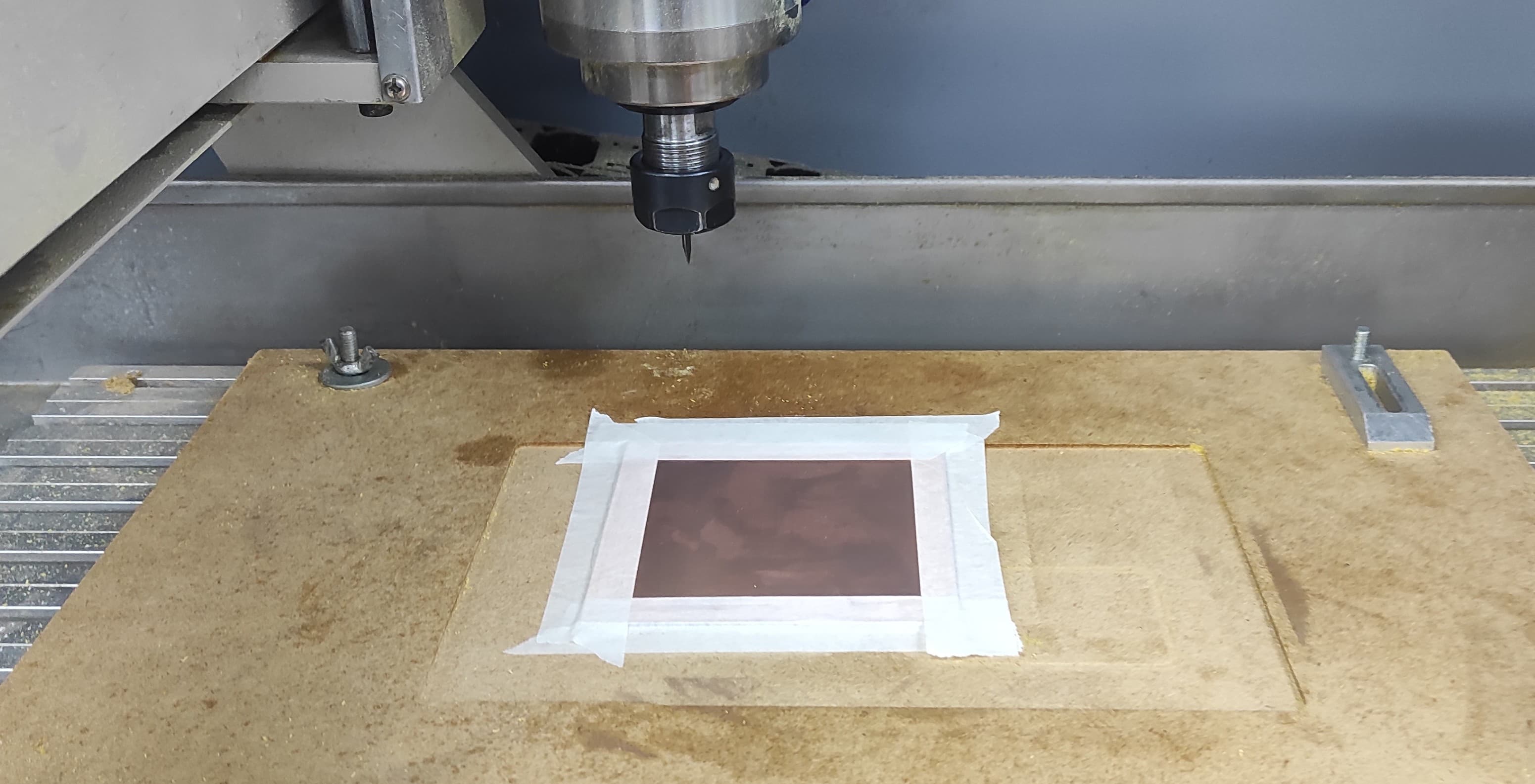
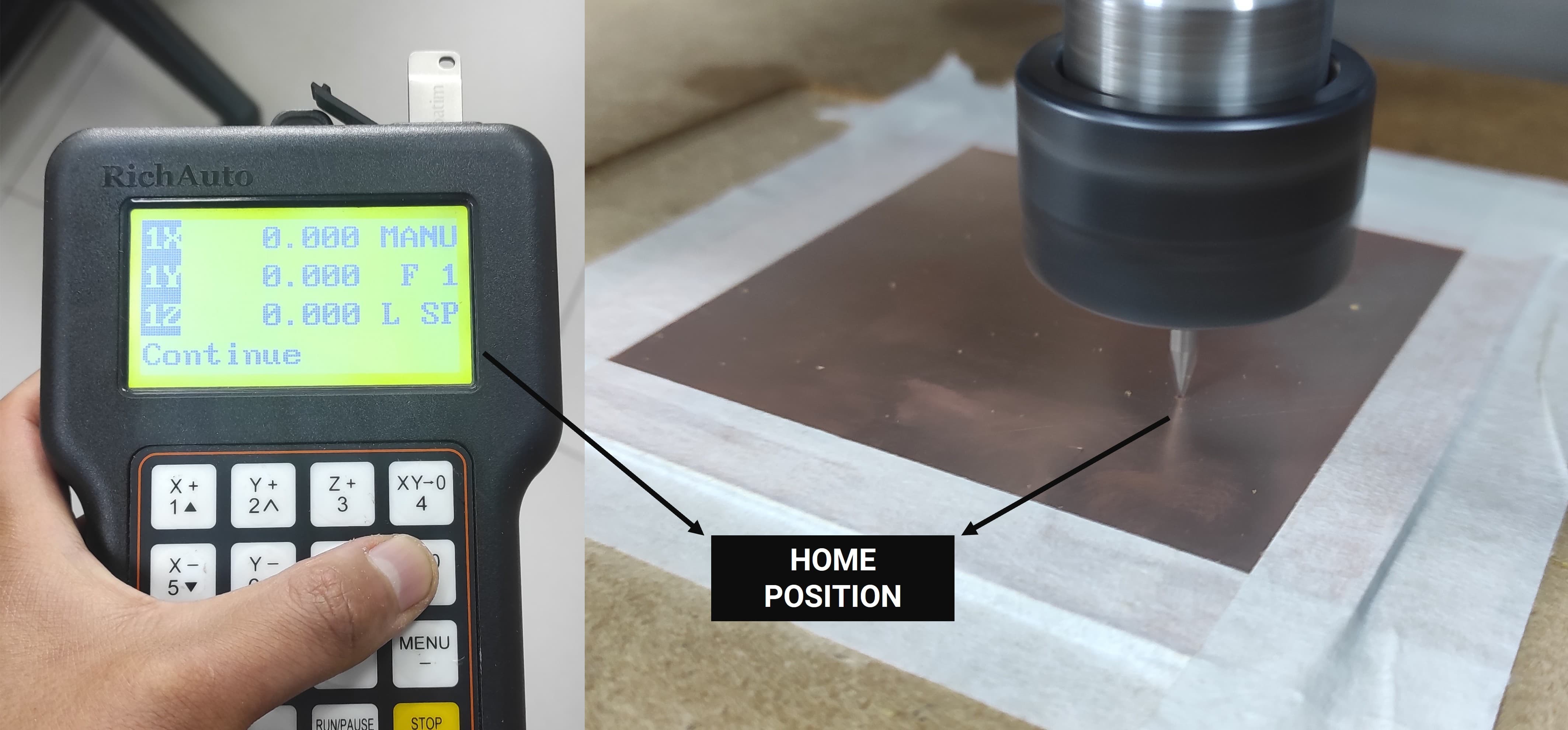
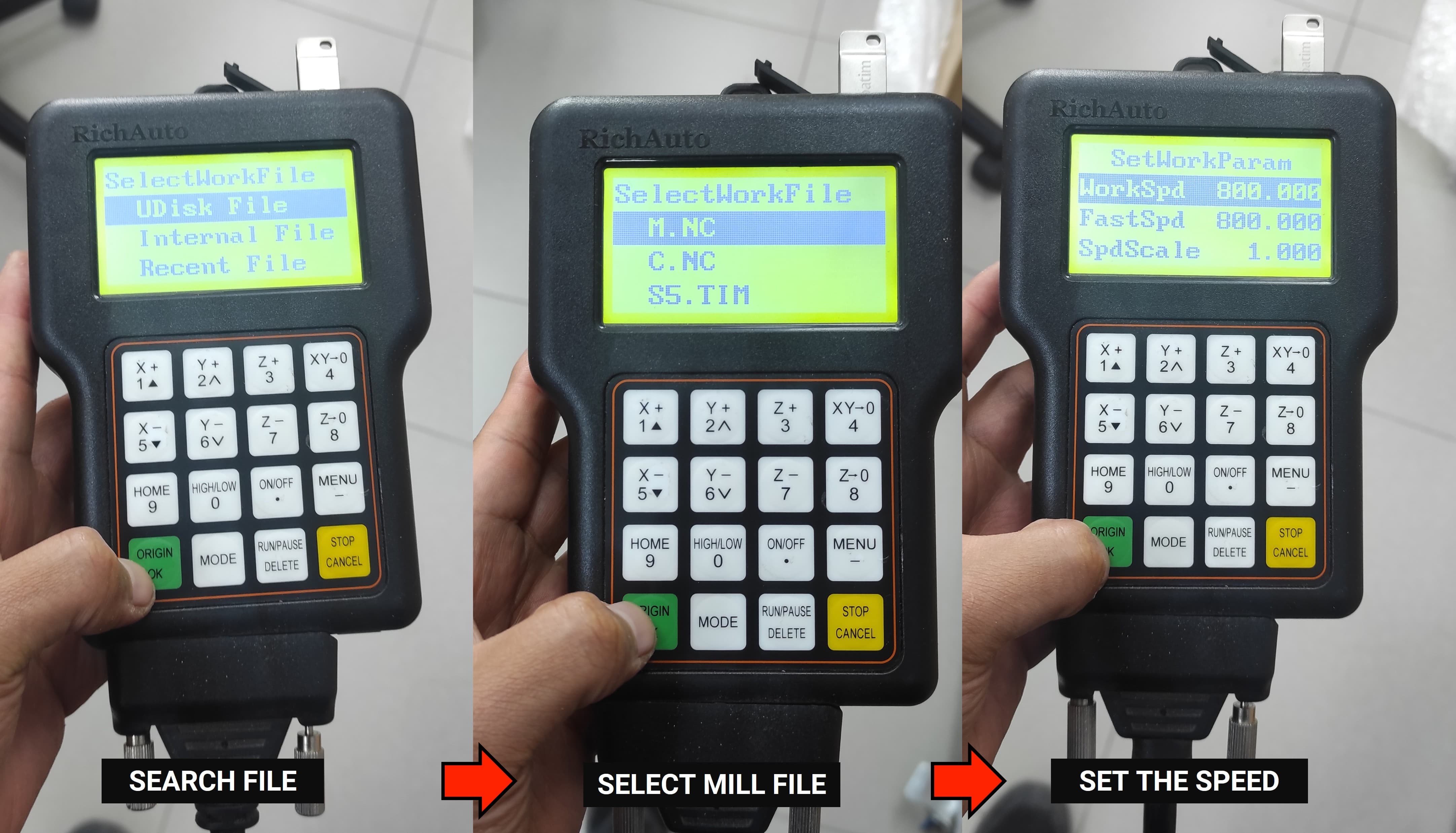
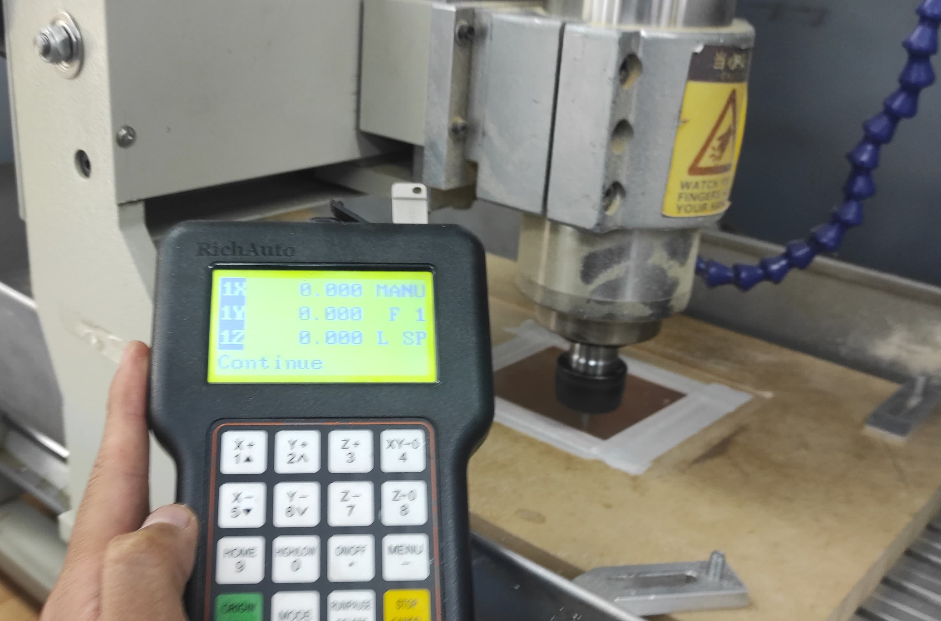
Once the PCB is secured with masking tape, we are ready to begin the milling process.
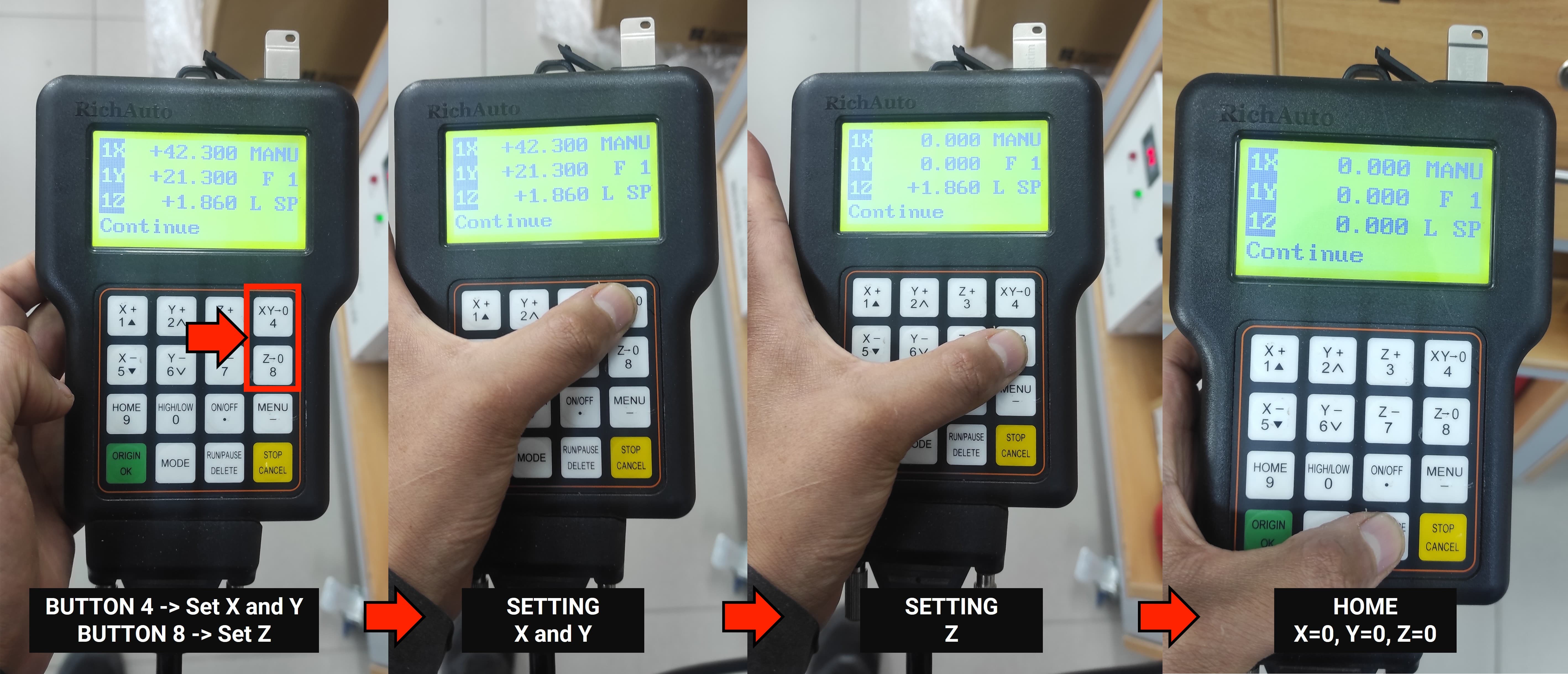
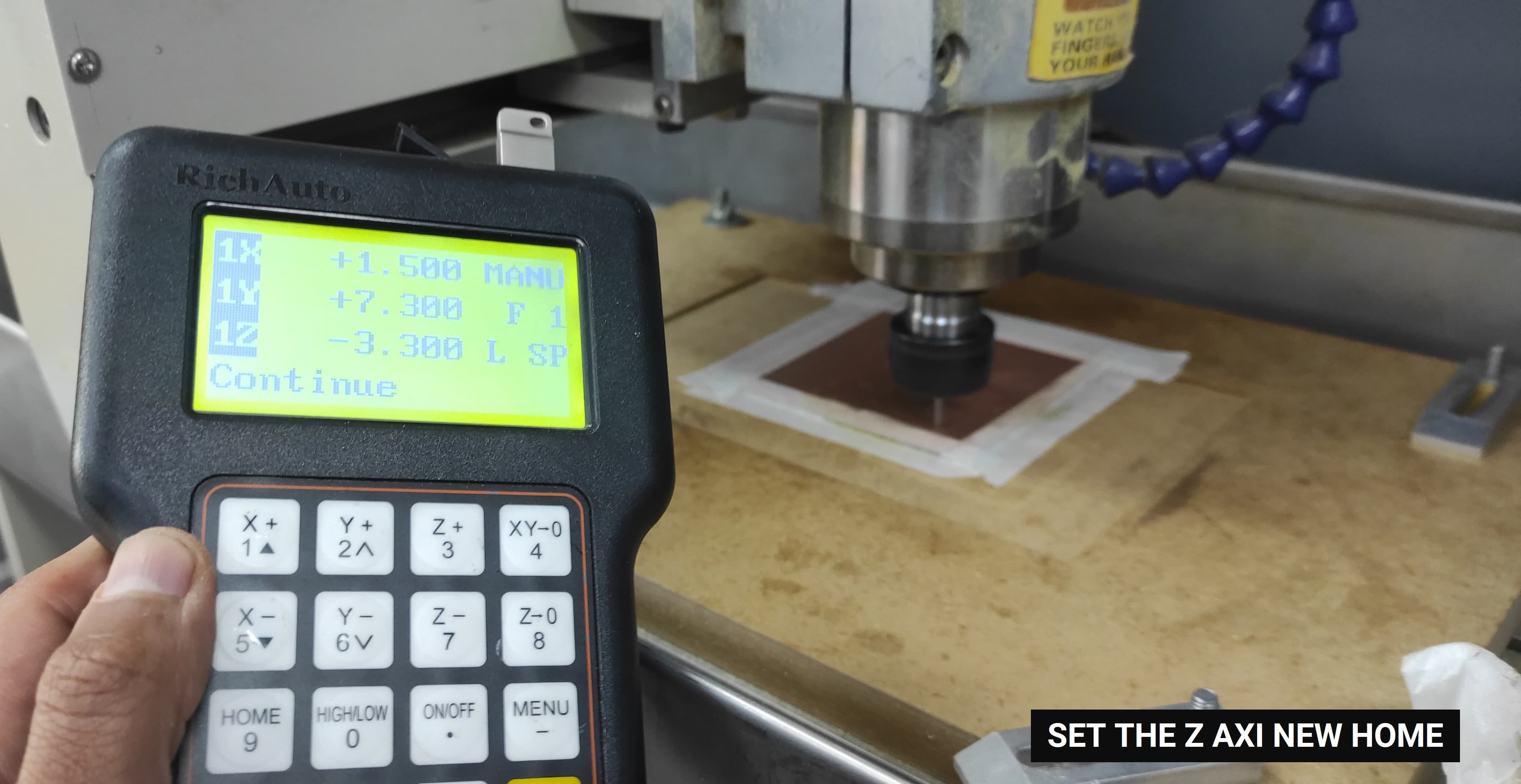
To set the new home position, first place the tool at the desired X, Y, and Z coordinates. Once the tool is in the correct position, use the DSP control to define the home position: press button 4 to set the X and Y home coordinates, and press button 8 to set the Z home coordinate.
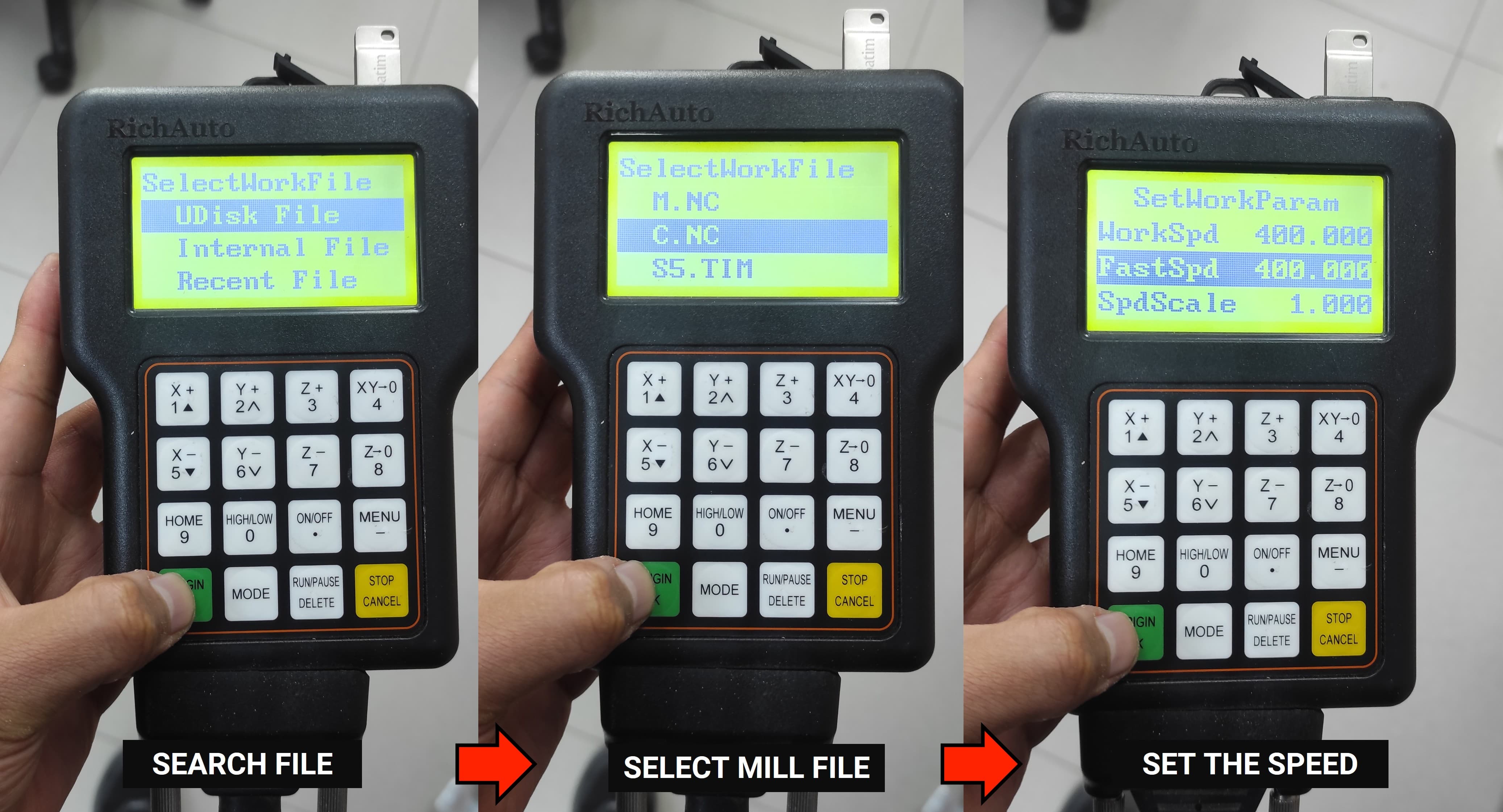
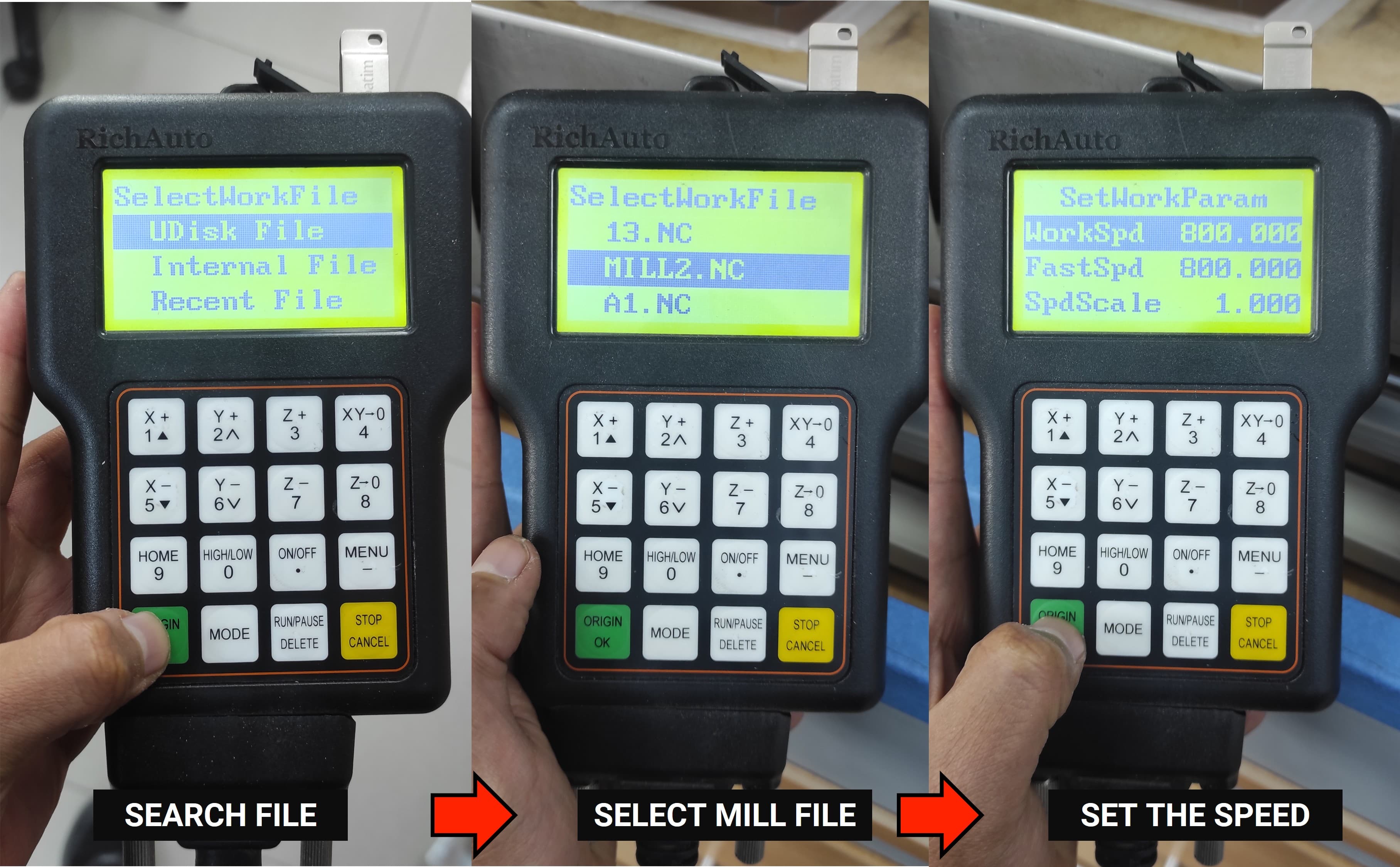
The next step is to select the file and execute the G-code.
Press OK and let's enjoy
Now We are going to continue cutting the PCB's outline, so lets keep on mind the following parameters:
Parameter
Value
Spindle Speed
14,000 RPM
Feed X-Y
400 mm/min
Plunge Rate
60 mm/min
Tool
Corn Endmill 3mm
Material
FR1
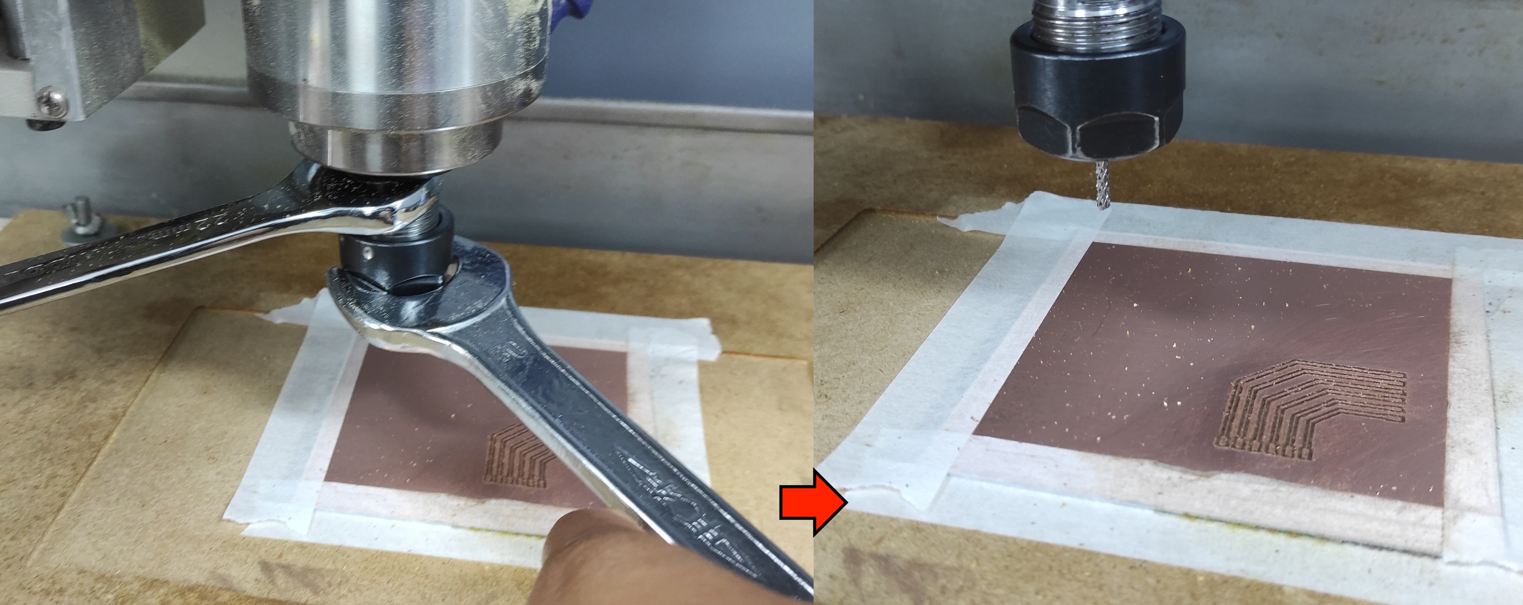
We need to change our tool for the Corn Endmill 3mm:
We need to set the Z axi new home because We changed to tool and the lenght is different
The next step is to select the file and execute the G-code.
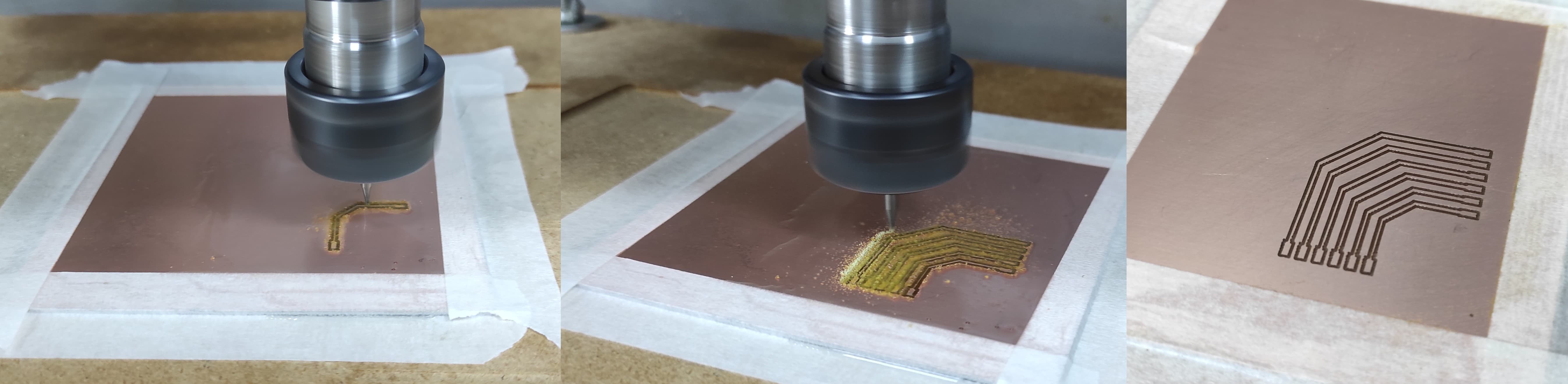
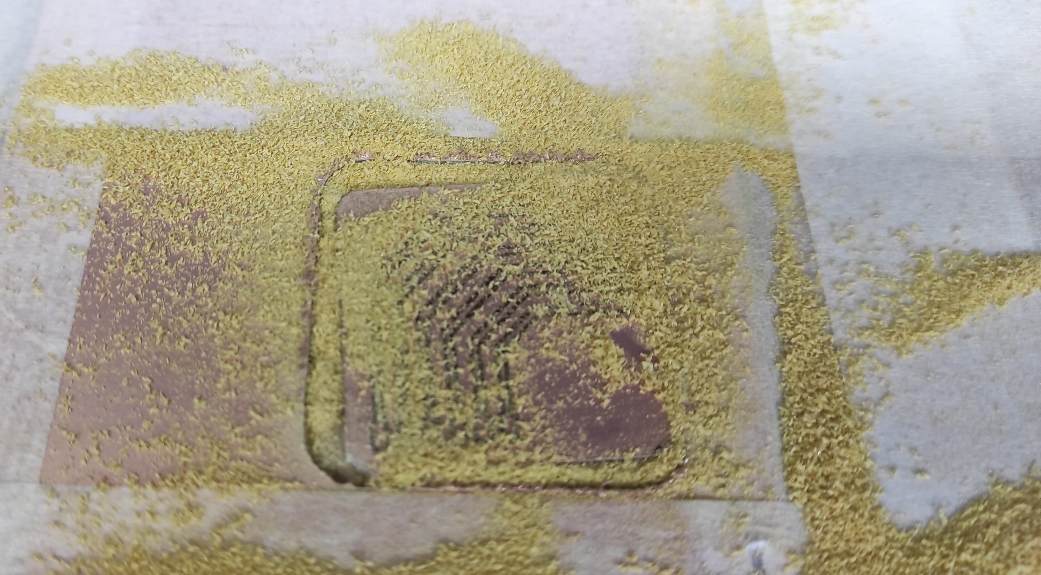
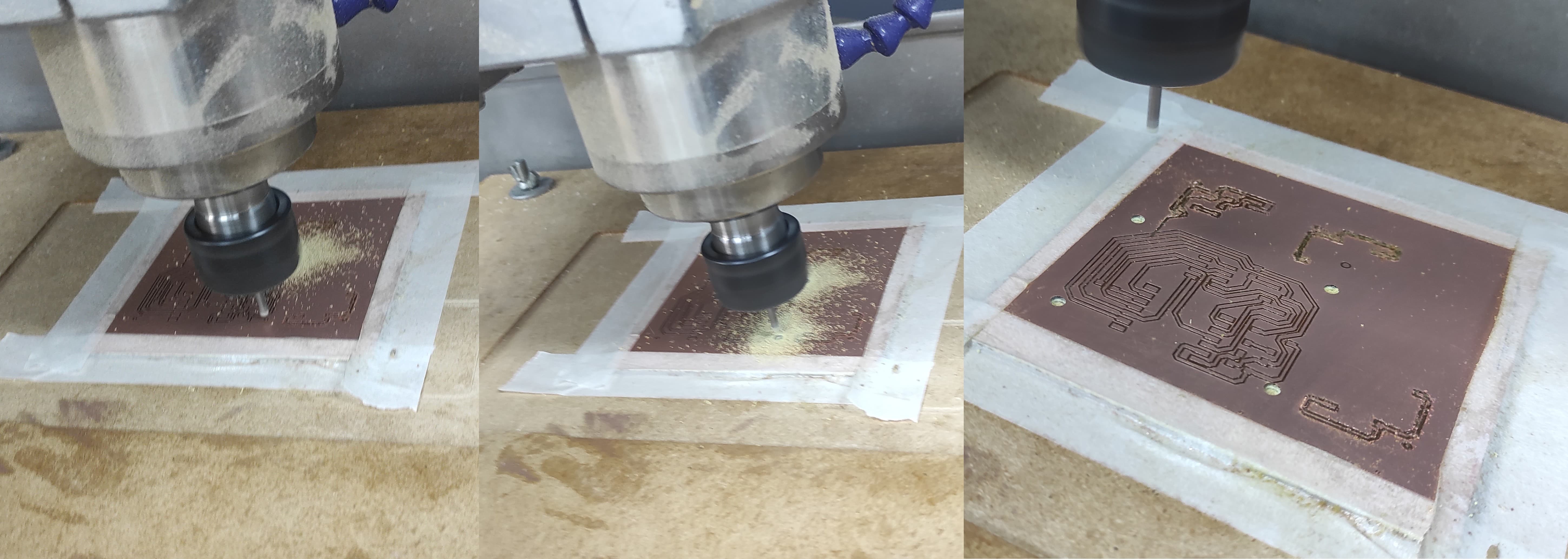
And here we have , our first pcb test.
4. PCB Test Results
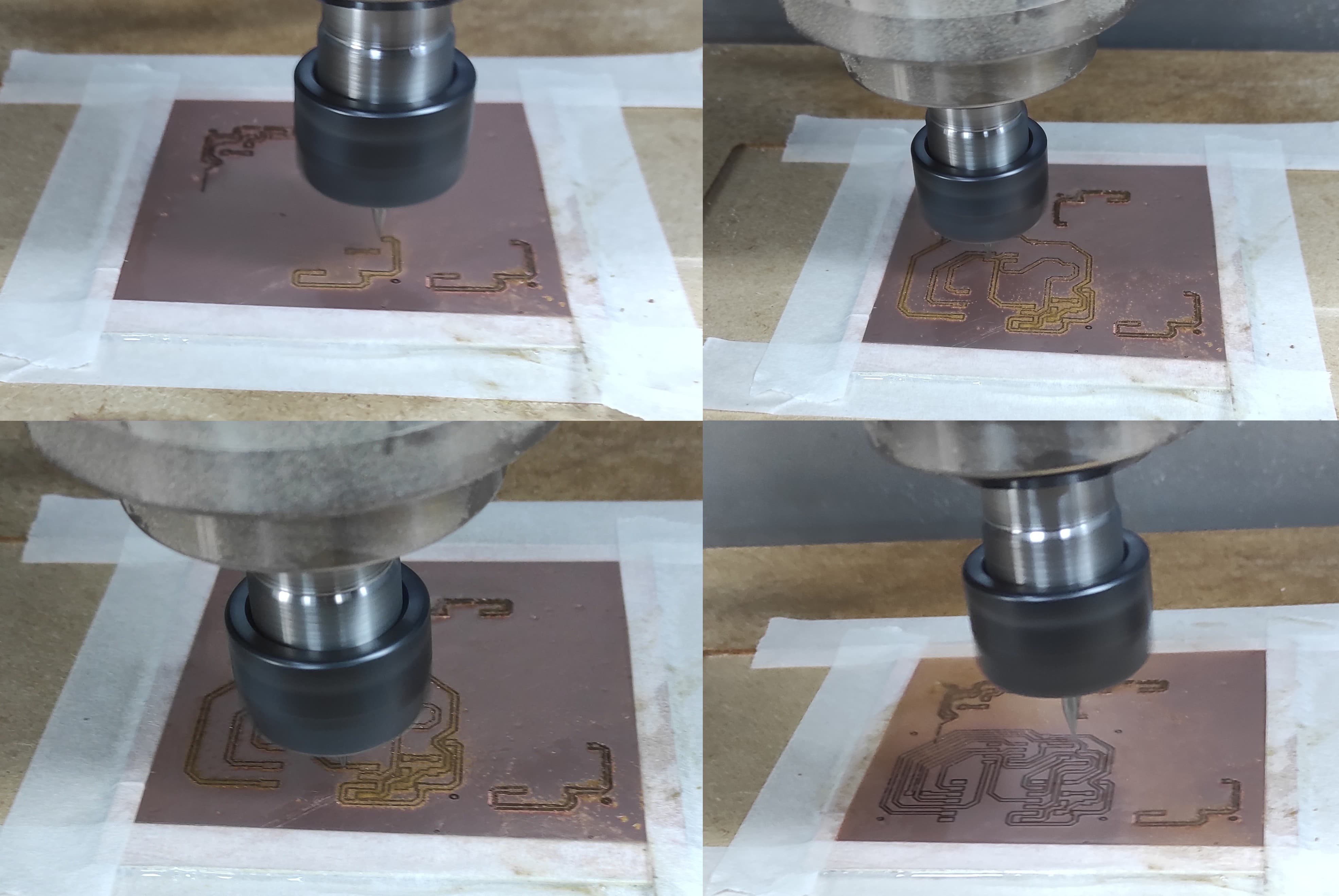
In the first test with traces ranging from 20 mil to 25 mil, we observed that some areas were not milled properly. This could be due to several factors, the most important being the tool home position and possible material deformation.
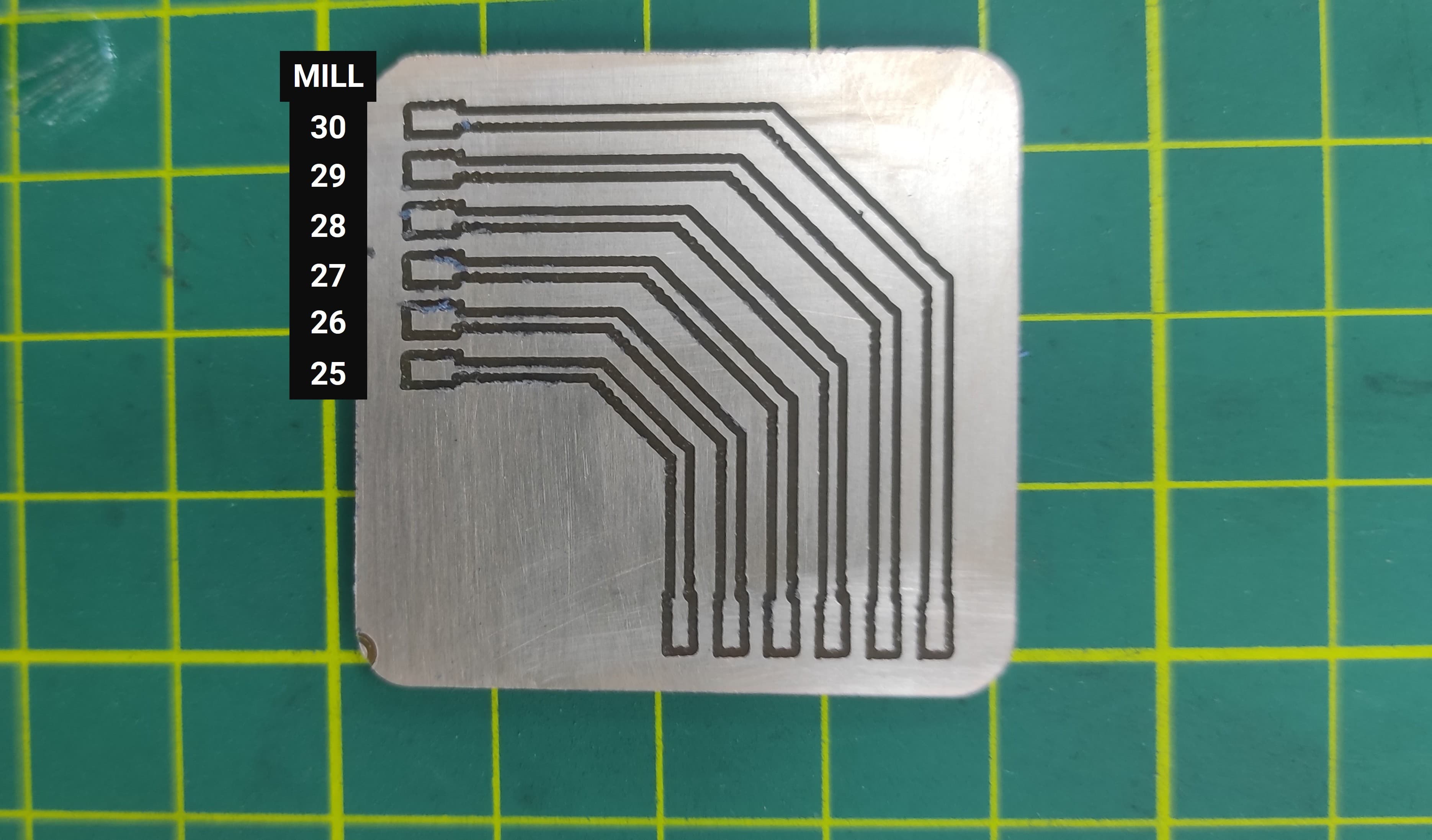
In the second test, the results were significantly better. All the traces were milled correctly, so these values can be used. However, it is important to ensure that the Z-axis is properly calibrated and that the material remains flat.
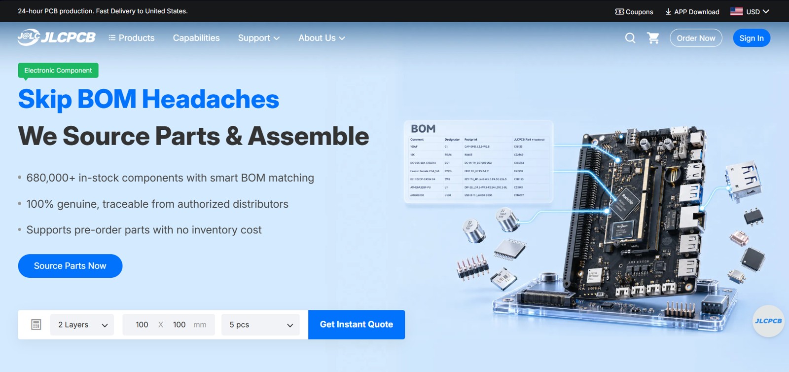
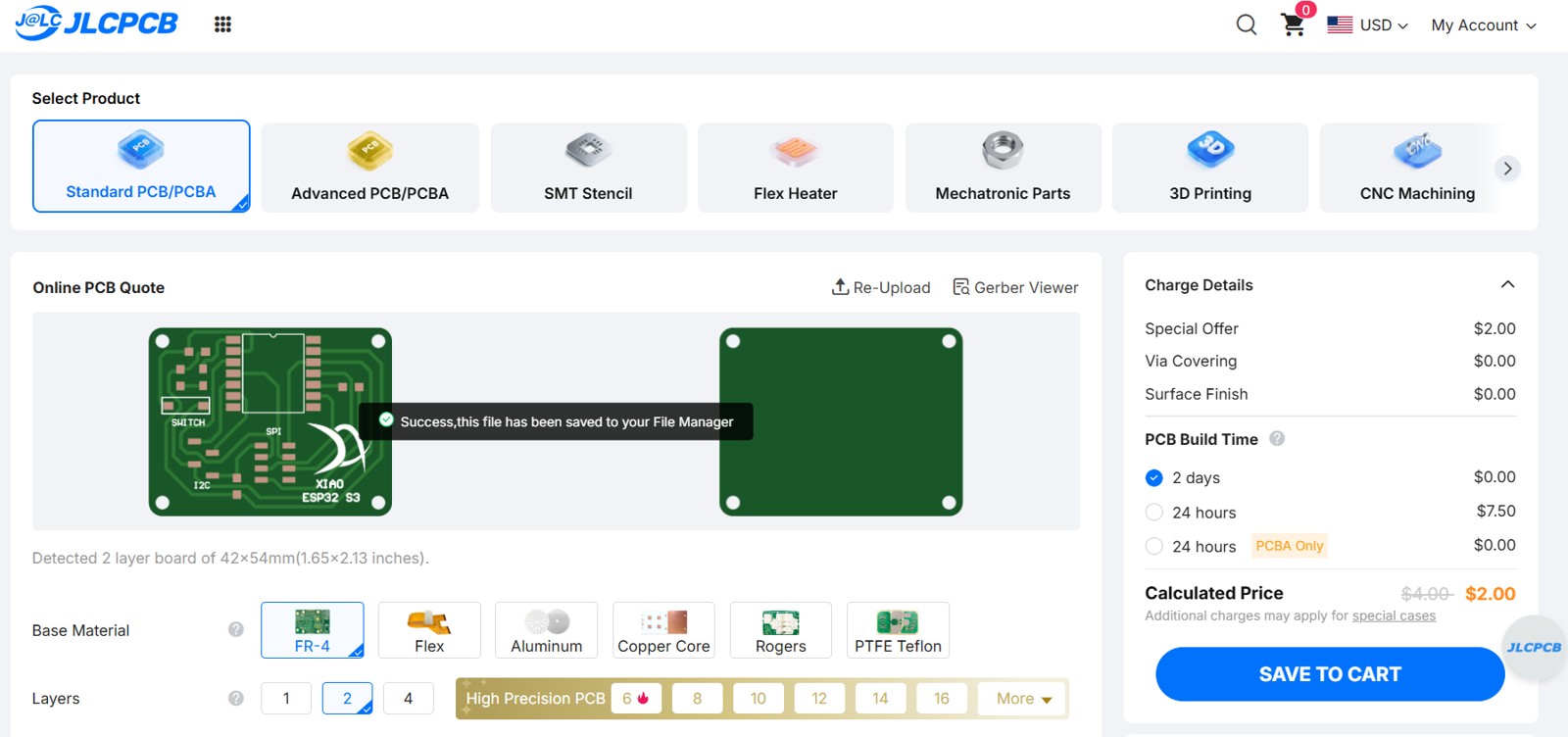
5. Sending a PCB to a boardhouse
To manufacture the PCB, I plan to use JLCPCB, as it appears to be a popular and reliable board house service.
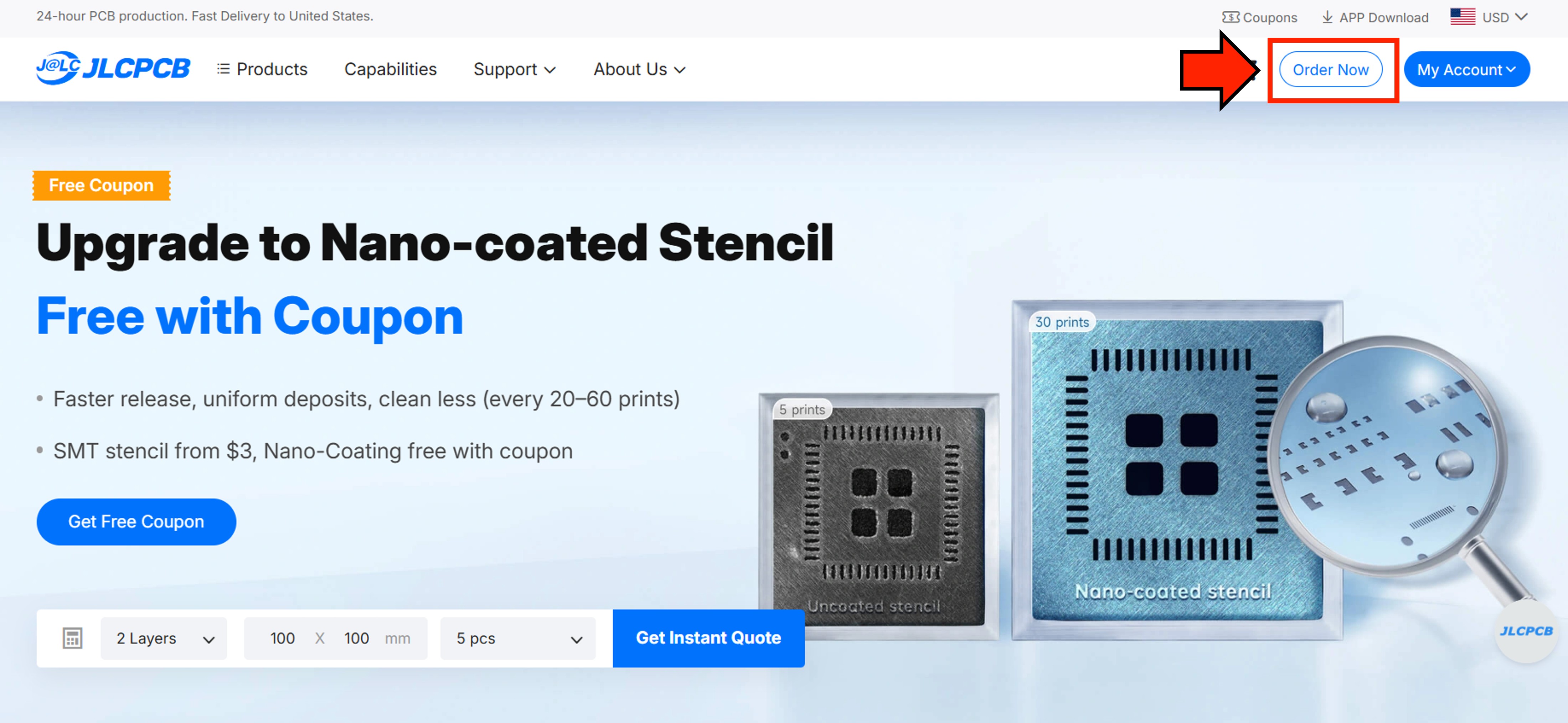
After registering and logging in, click the Order Now button.
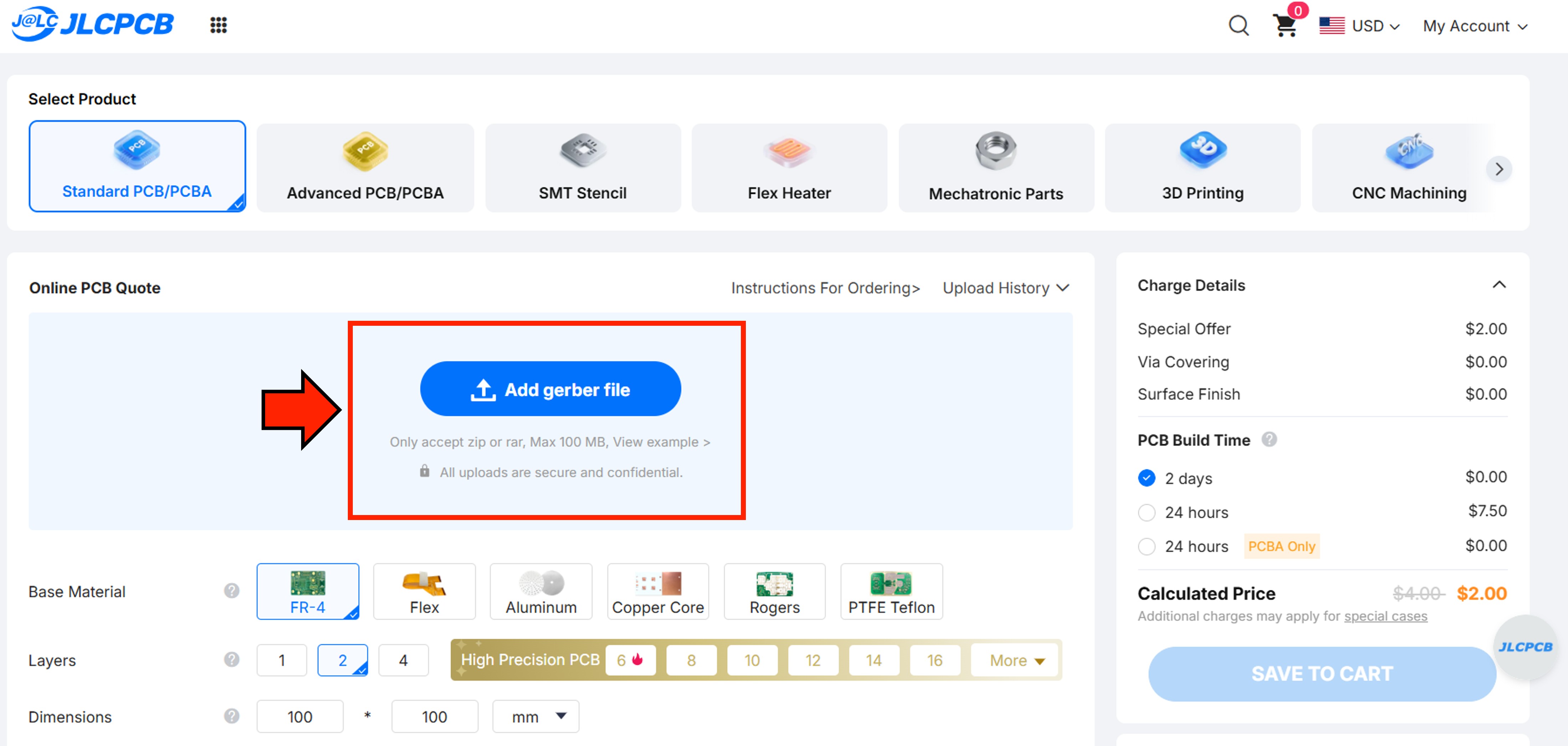
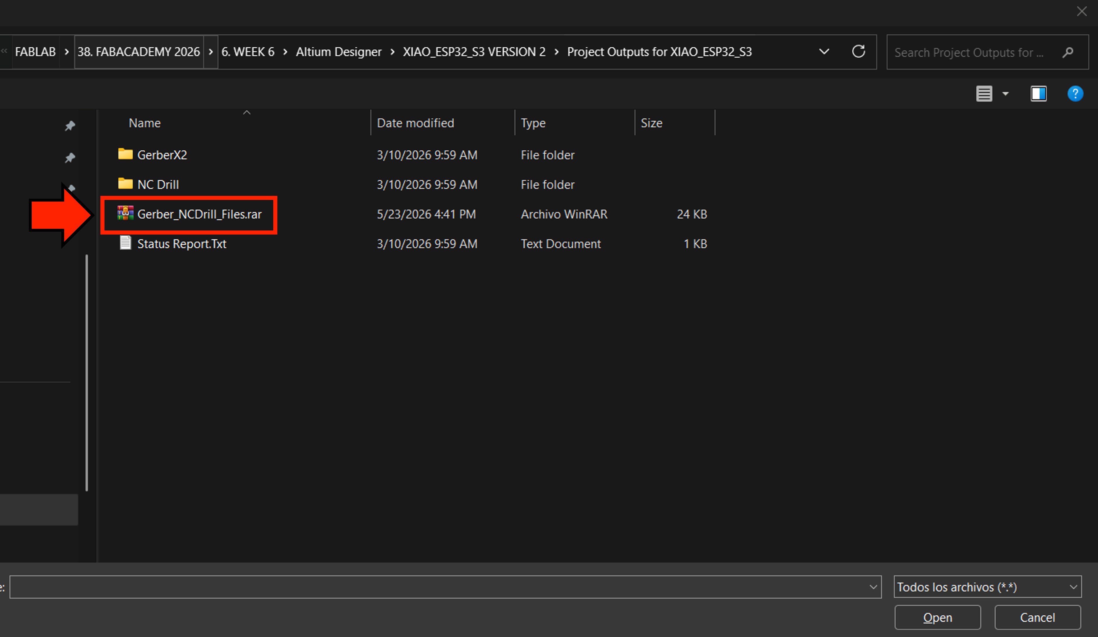
Next, we need to upload the Gerber files of our PCB design.
The Gerber files and NC Drill files must be included together in a single compressed file.
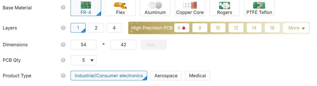
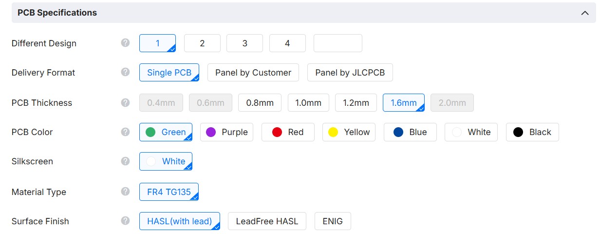
After uploading the files, we can preview the PCB. Once the preview looks correct, we can proceed to configure the board parameters as well.
The PCB is a single-sided board, so we will select the configuration shown in the image below.
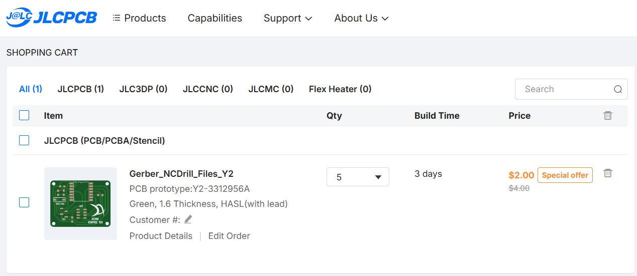
After selecting the configuration, we can now see the cost of the PCBs.
The final step is to enter the shipping address and complete the payment.
Individual Assignment
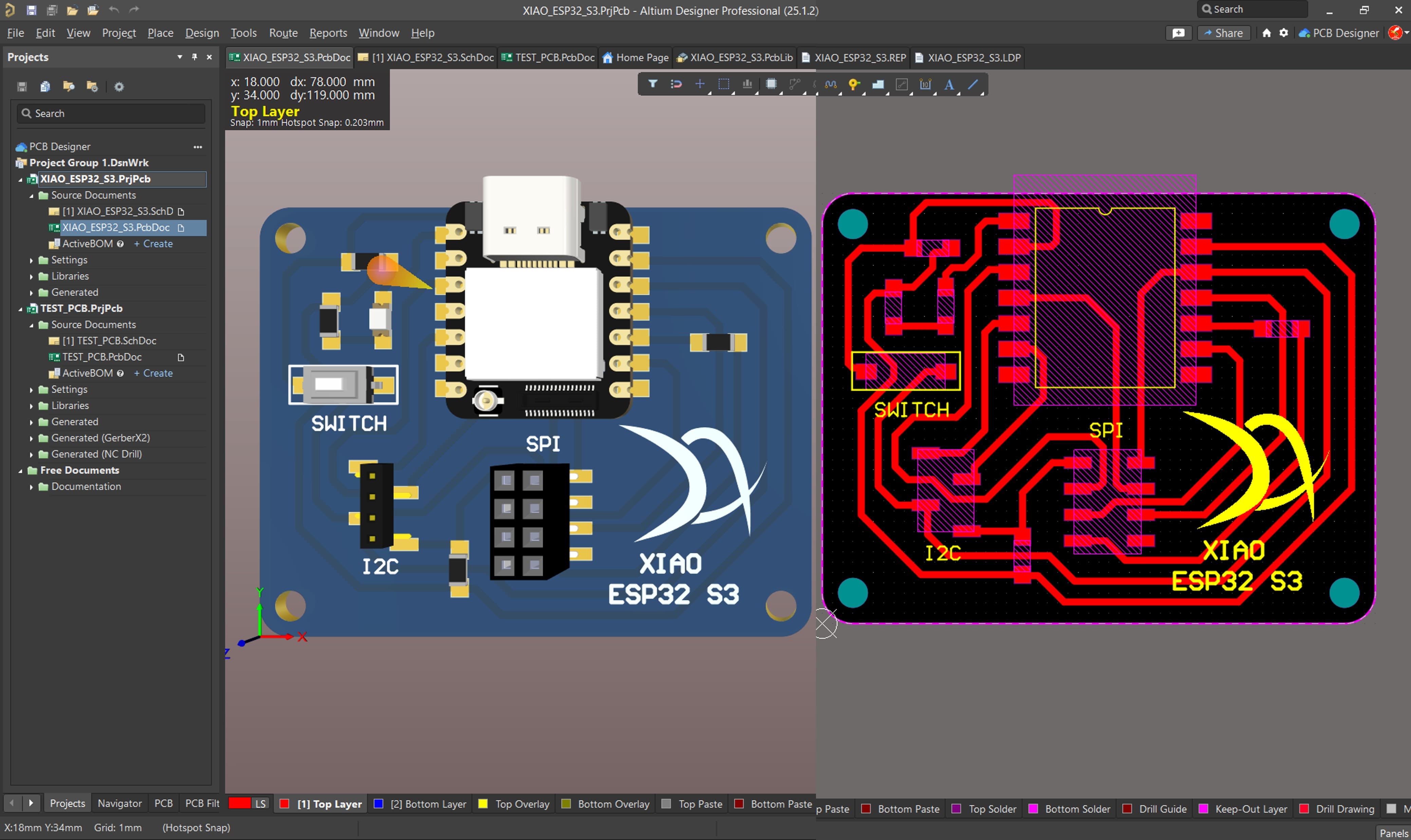
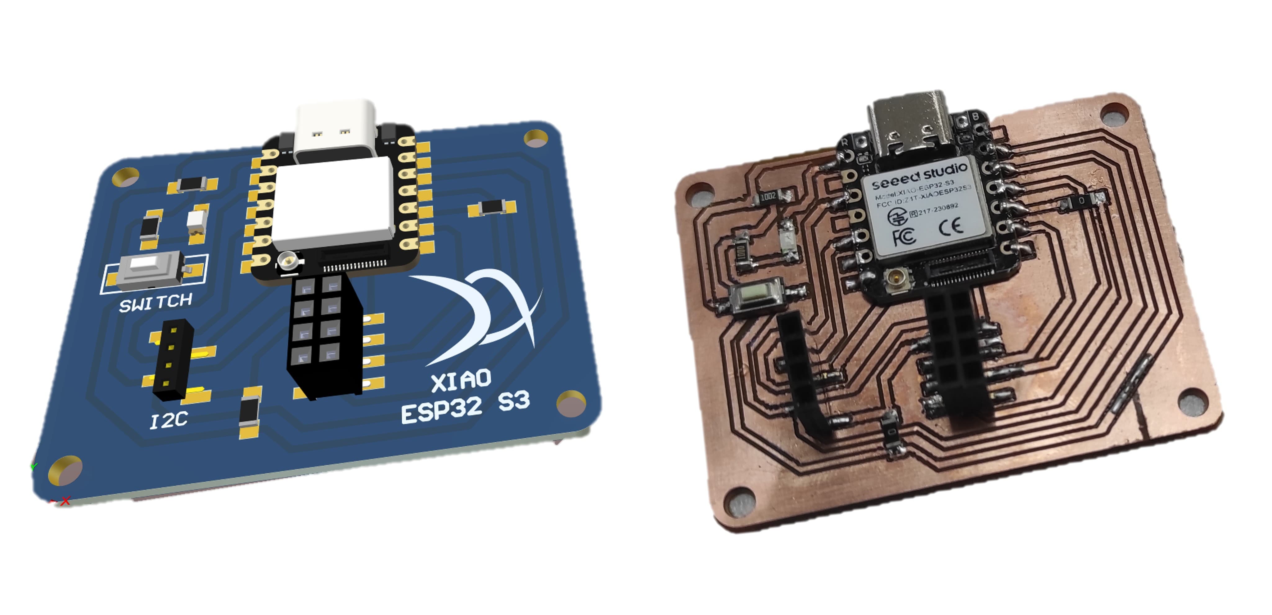
5. Microcontroller PCB
5.1 PCB XIAO Esp32 S3 Sense
The PCB board that we are going to manufacture will work with a XIAO ESP32 S3 Sense, and will include one LED, one switch, one SPI port, and one I2C port.
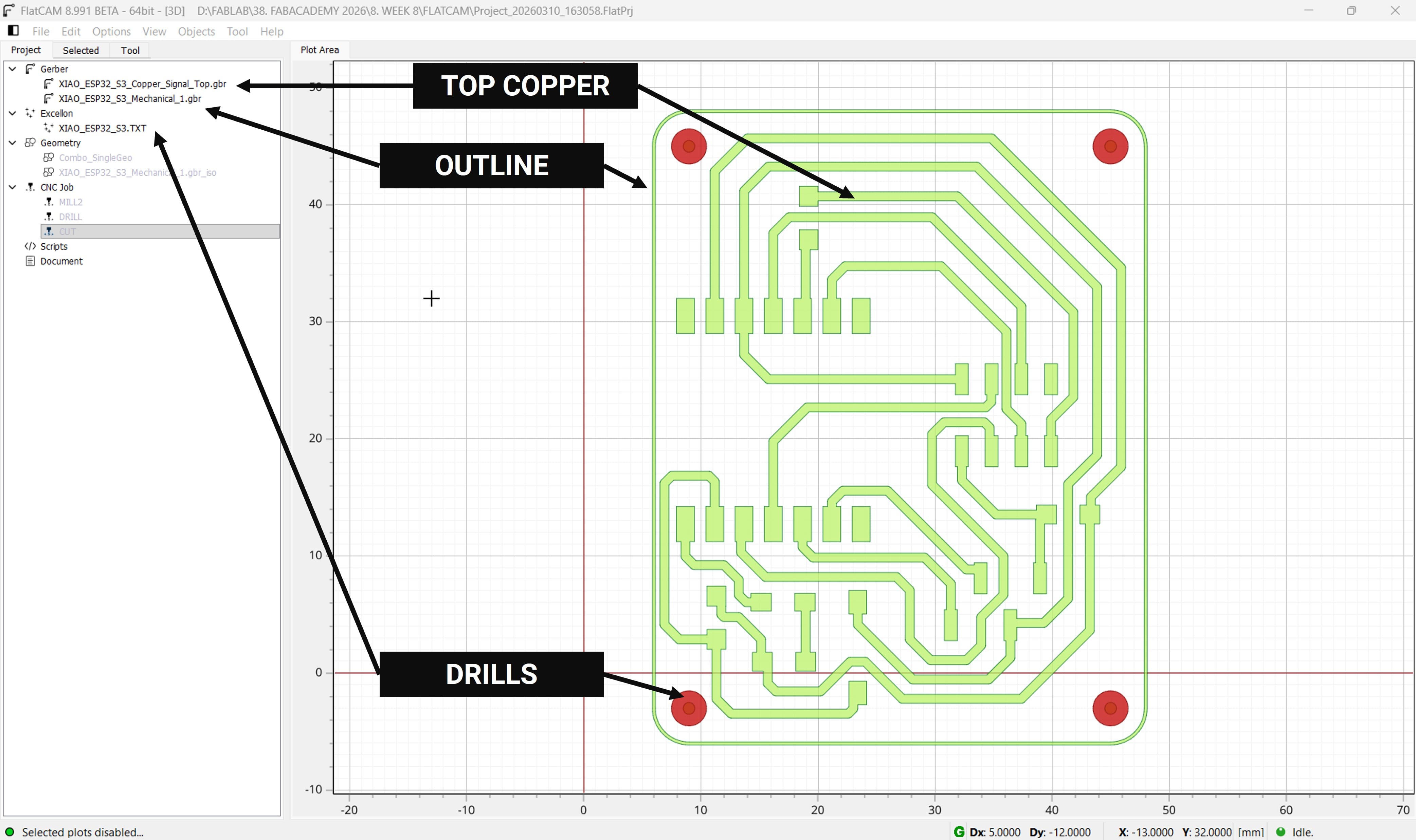
5.2 Generating the Gcode Files
First, we import the Gerber files corresponding to the Top Copper layer,the PCB outline and NC Drills.
First, we mill the traces on the top copper layer using a 0.2188 mm diameter tool, as calculated previously in our test.
Next, we generate the G-code files using the parameters validated in the previous test.
Now We continue with the PCB's Outline.
Next, we generate the G-code files using the parameters validated in the previous test.
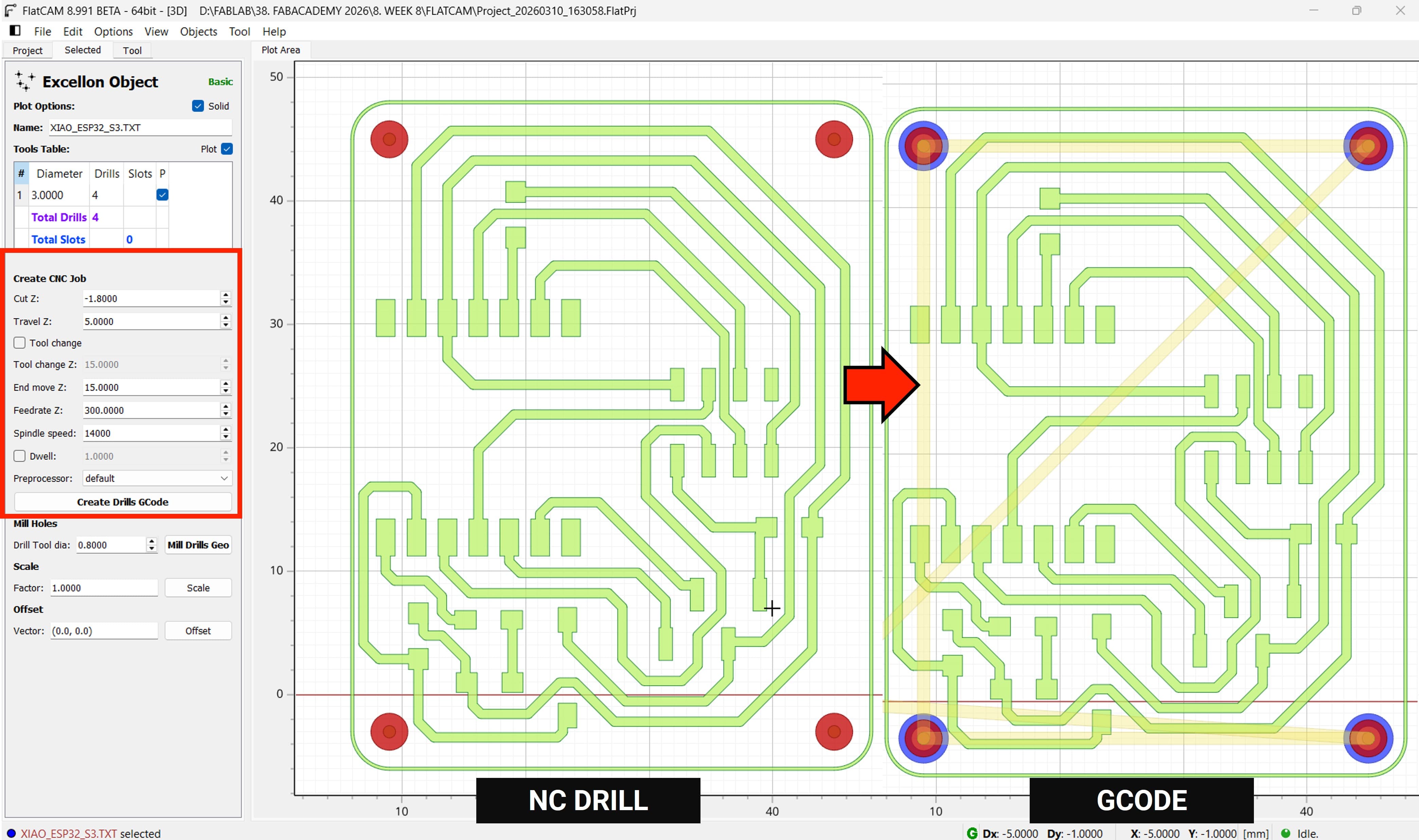
Finally, we generate the G-code files for the drills .
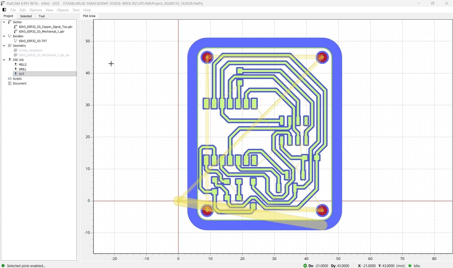
Done, We have all the Gcode that We need for now
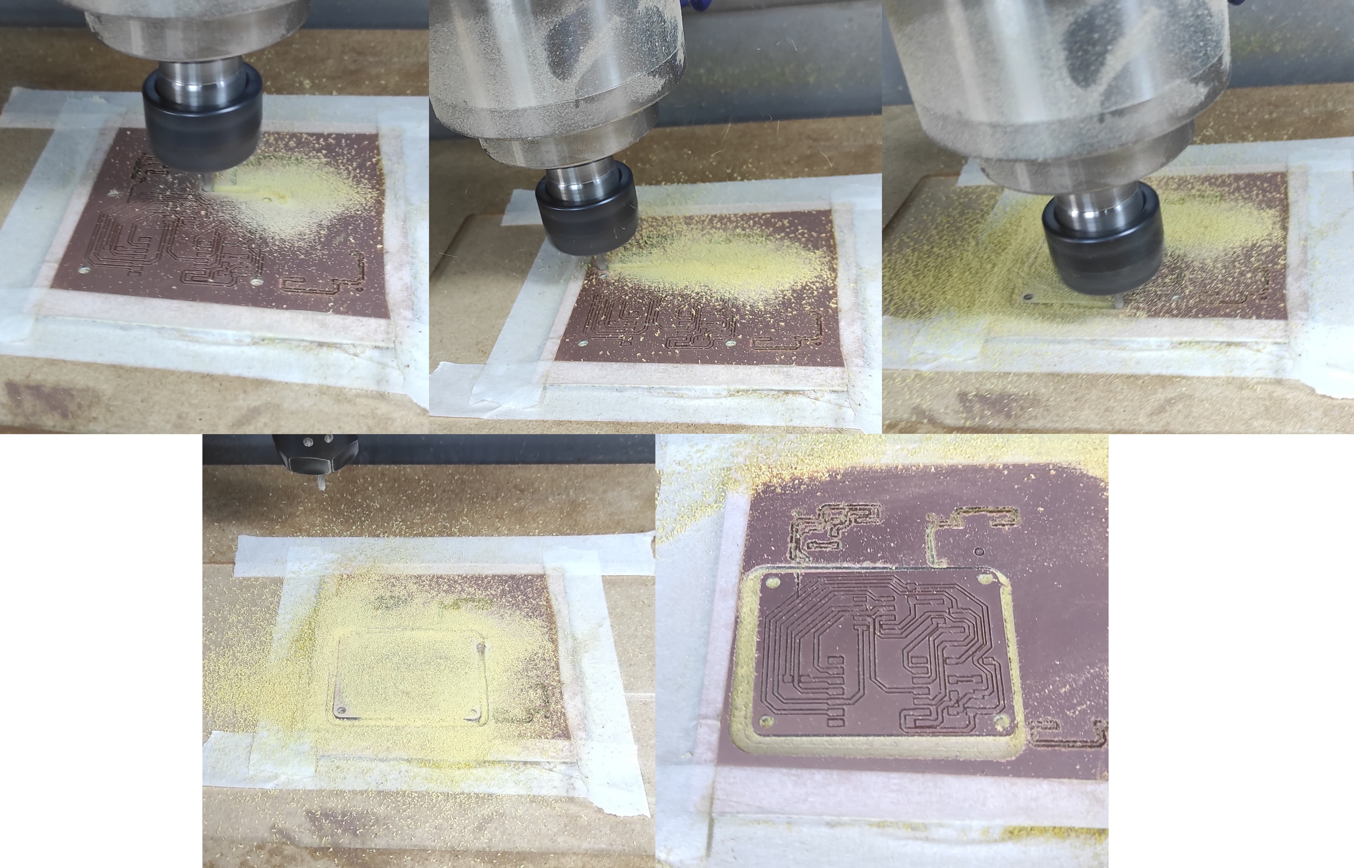
5.3 PCB Fabrication process
Let's begin the manufacturing process by starting with the milling operation.
After setting the Home position. We select the milling GCode
Press OK, and the machine will complete the rest of the process.
We are going to repeat the same process for the drilling and cutting operations.
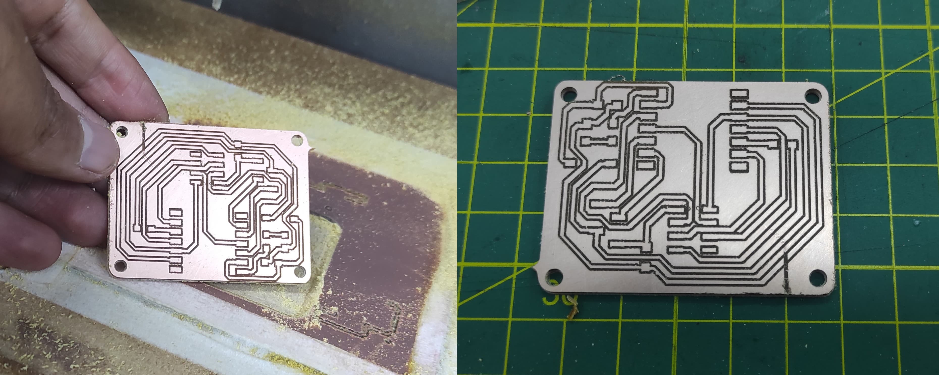
Finally We have our PCB Board
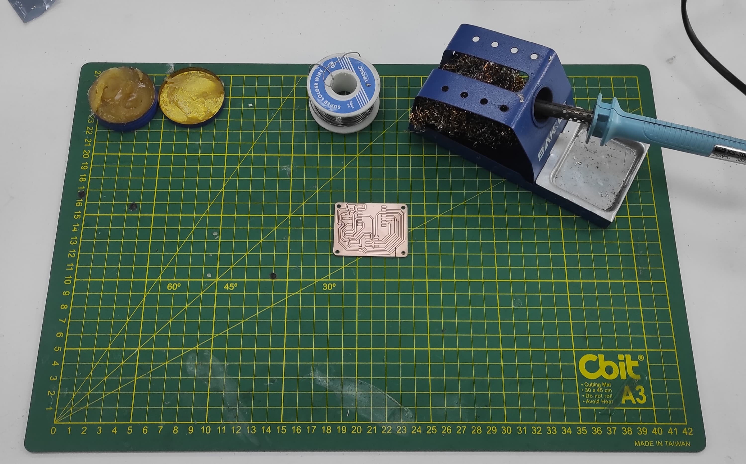
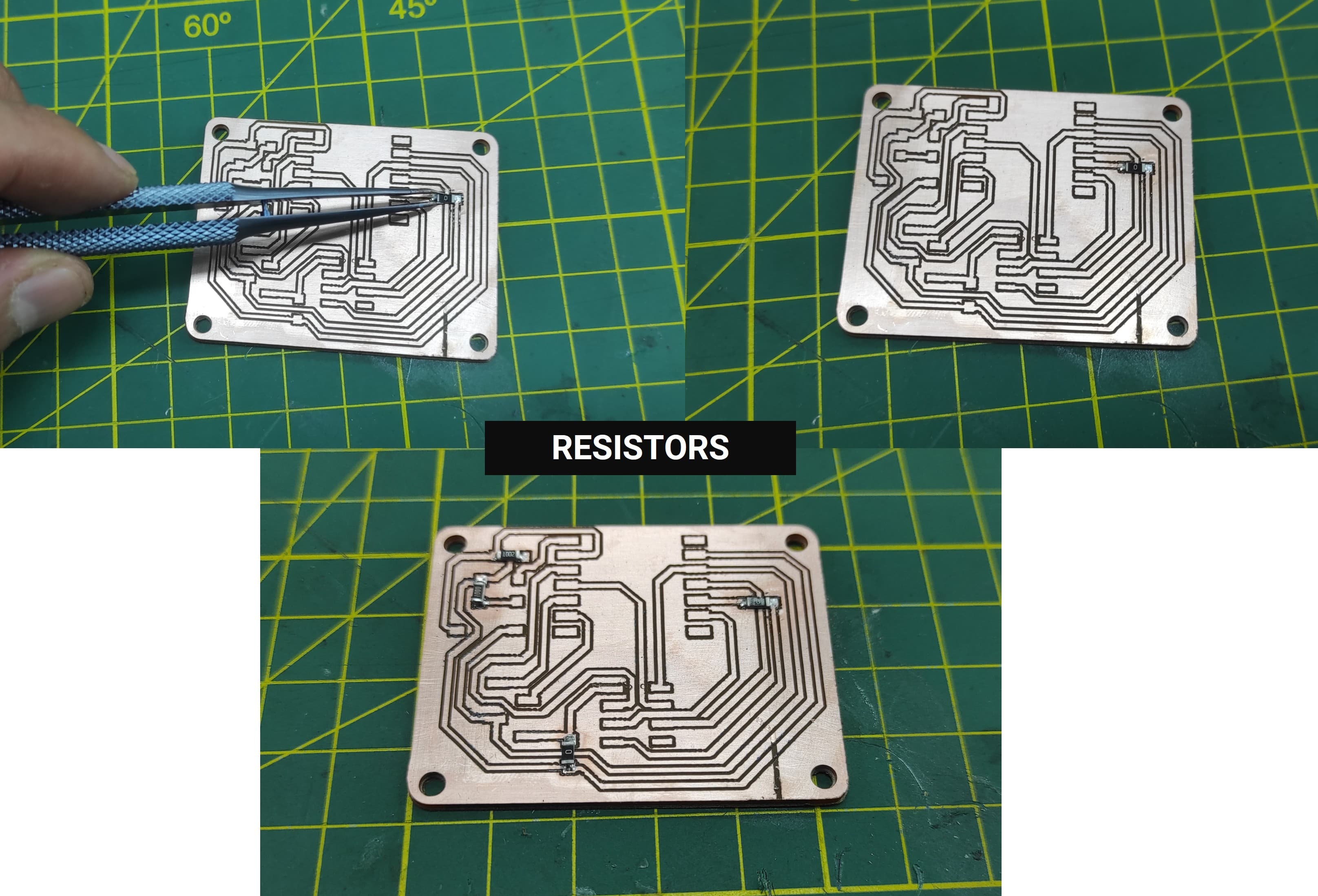
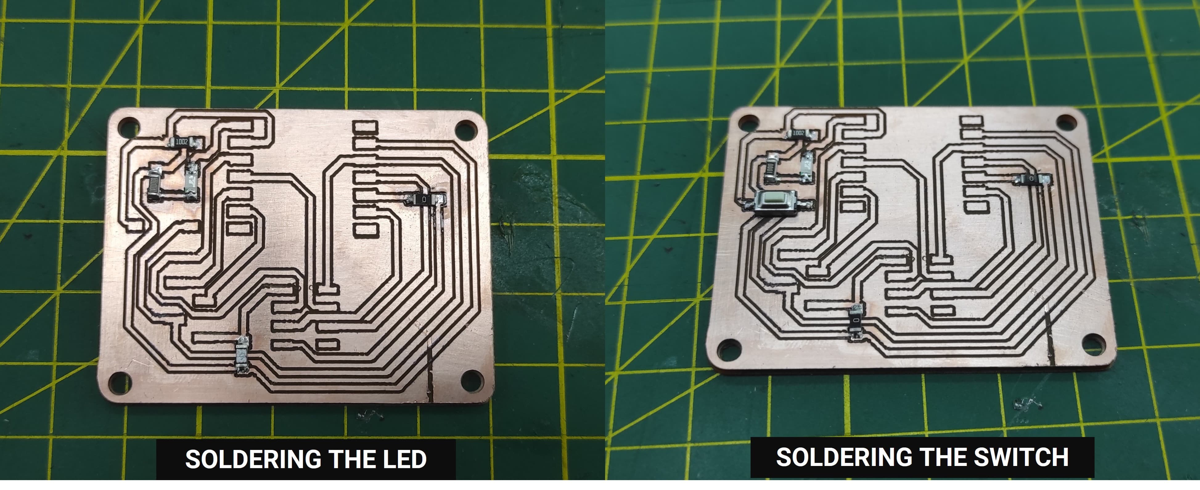
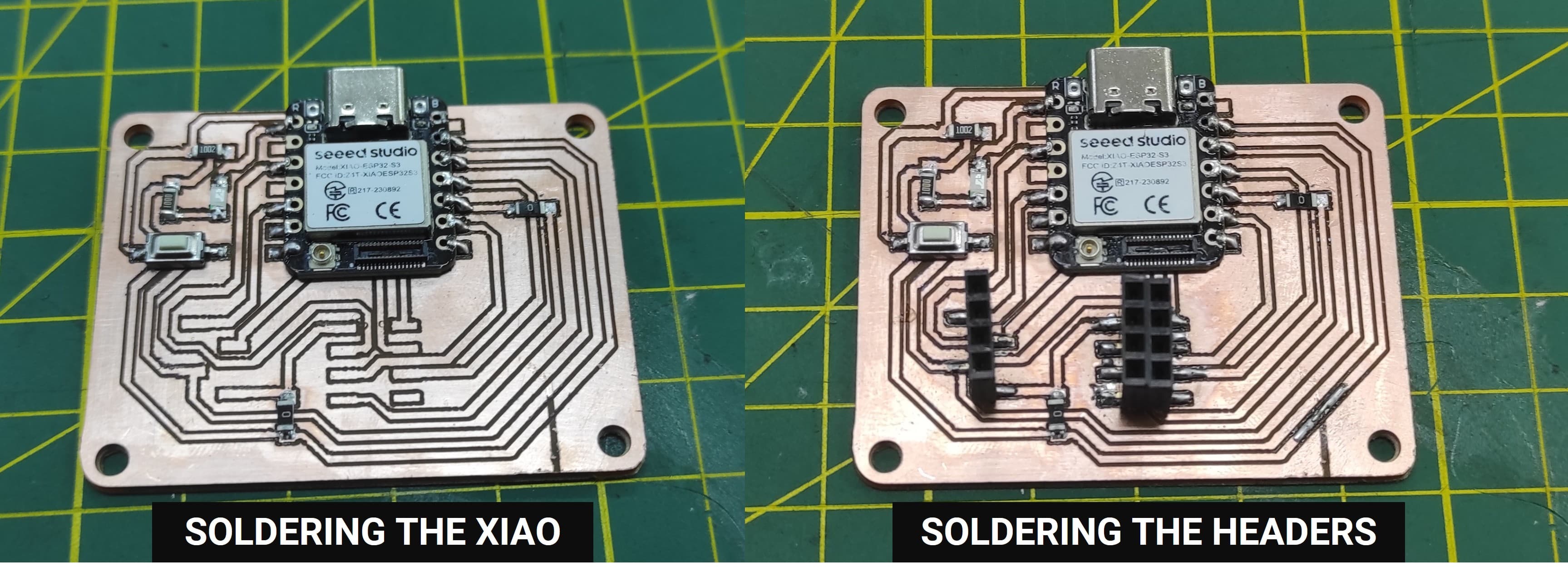
5.4 Soldering the components
Now we will continue soldering the different components of our PCB. For this step, we need a soldering iron, solder wire, flux, tweezers, and the electronic components. It is important to carefully place each component in the correct position on the board and apply the right amount of solder to ensure good electrical connections. We start by soldering the smaller components first and then continue with the remaining parts.
5.5 Testing the PCB
To test the PCB, we will run a simple LED blink program. This program allows us to verify that the microcontroller, the LED, and the power connections are working correctly. If the LED turns on and off at regular intervals, it confirms that the board has been successfully assembled and programmed.
During this project, several important lessons were learned throughout the PCB design, milling, assembly, and testing process. One of the key learnings was the importance of proper machine calibration, especially setting the correct tool home position and Z-axis, since even small height variations can affect the quality of the milled traces. Performing initial milling tests helped determine the appropriate parameters, such as the tool diameter (0.2188 mm) and trace settings, which significantly improved the final results. We also learned that securely fixing the PCB material and ensuring a flat surface is essential to achieve consistent milling depth. During the assembly stage, developing careful soldering techniques was important to correctly place and connect the electronic components without creating short circuits. Finally, testing the board with simple programs, such as a basic LED blink and a button-controlled LED, helped verify that the microcontroller, inputs, outputs, and electrical connections were functioning correctly, demonstrating the importance of iterative testing and troubleshooting in the PCB manufacturing process.