Week 7 Progress Checklist
| Status | Task |
|---|---|
| ✓ | Linked to the group assignment page |
| ✓ | Reflected on your individual page what you learned of your labs safety training |
| ✓ | Documented how you designed your object and made your CAM-toolpath |
| ✓ | Documented how you milled and assembled your final product (including setting up the machine, fixturing, feeds, speeds etc.) |
| ✓ | Described problems and how you fixed them |
| ✓ | Included your design files and 'hero shot' of your final product |
Computer-Controlled Machining
Group Assignment
1. Safety Considerations for CNC Router Machines
1.1 🦺 Personal Protective Equipment (PPE)
Before operating a CNC router, wearing the correct PPE is a critical first step to protect against common hazards. It prevents movement, kickbacks, tool breakage, and tripping hazards.
| Eye Protection: Safety glasses are essential to guard against flying chips, dust, and debris generated during routing. |

|
| Hearing Protection: CNC routers can be very loud. Ear protection, such as ear muffs or plugs, should be worn to prevent hearing damage. |

|
|
Clothing and Hair: Avoid loose‑fitting clothing, untucked shirts, and items with tassels. Tie back long hair and beards to prevent them from getting caught in moving parts. A critical warning: Do not wear gloves while operating the machine, as they can easily be caught by rotating cutters. |

|
| Respiratory Protection: Machining wood and other materials creates fine dust. A nose cover, dust mask, or respirator should be worn, especially if dust collection is not perfectly efficient. |

|
2. CNC Router - Description
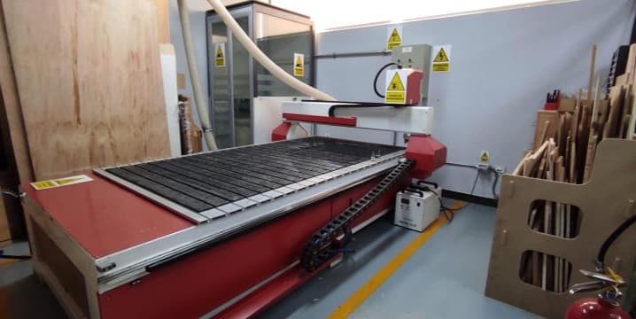
2.1 CNC Router – Yinghe X1325
The Yinghe X1325 is a robust 3‑axis CNC router widely used for woodworking and non‑metal machining. It features a large 1300 x 2500 mm work area, a cast‑iron structure for stability, and a water‑cooled spindle (typically 3.2 kW to 5.5 kW) that runs at up to 24,000 rpm. The machine is often controlled by a dedicated RichAuto DSP controller, which reads standard G‑code directly from a USB drive, eliminating the need for a connected computer during operation. Common applications include cutting, carving, and engraving materials such as wood, MDF, acrylic, and soft metals. Proper use requires attention to safety (ear protection, safety glasses), reliable dust extraction, and high‑quality tooling like solid carbide end mills to achieve clean results and prevent tool breakage.
Yinghe X1325 CNC Router
| Technical Specifications | Details |
| Brand | Yinghe |
| Model | X1325 |
| Working Area | 1300 x 2500 mm |
| Positioning Accuracy in X, Y, Z Travel | ±0.03/300 mm |
| Repositioning Accuracy in X, Y, Z | ±0.01 mm |
| Lathe Structure | Cast Iron |
| Y Structure | Square Orbit, Ball Screw |
| X, Z Structure | Square Orbit, Ball Screw |
| Maximum Power Consumption | 3.2 KW |
| Maximum Speed | 0-4000 mm/min |
| Maximum Working Speed | 0-3000 mm/min |
| Spindle Motor Power | 3.2 KW |
| Spindle Speed | 24000 rpm |
| Working Mode | Step |
| Working Voltage | AC 220 V/50 Hz |
| Domain | G Code, uoo, mmg |
| Operating System | Rich Auto |
| Flash Memory | 32M |
| Blade Diameter | Φ3.175, Φ4, Φ6 |
| X, Y Working Precision | <0.02 mm |
| Software | Software, Type 3, Artcam |
| Packaging | 12CBM |
| Gross Weight | 780 kg |
3. CNC Machine Testing
To test the CNC cutting tolerances, I prepared a file using 14.5mm thick plywood. I cut several pieces with progressively decreasing slot sizes, reducing the width by 0.1mm increments: 14.5mm, 14.4mm, 14.3mm, 14.2mm, 14.1mm, and 14.0mm. This allowed me to determine the optimal fit for assembly.
| Parameter | Value |
|---|---|
| Spindle Speed | 20,000 RPM |
| Feed Rate | 2,000 mm/min |
| Plunge Rate | 600 mm/min |
| Tool | 4mm endmill |
| Material | 14.5mm plywood |
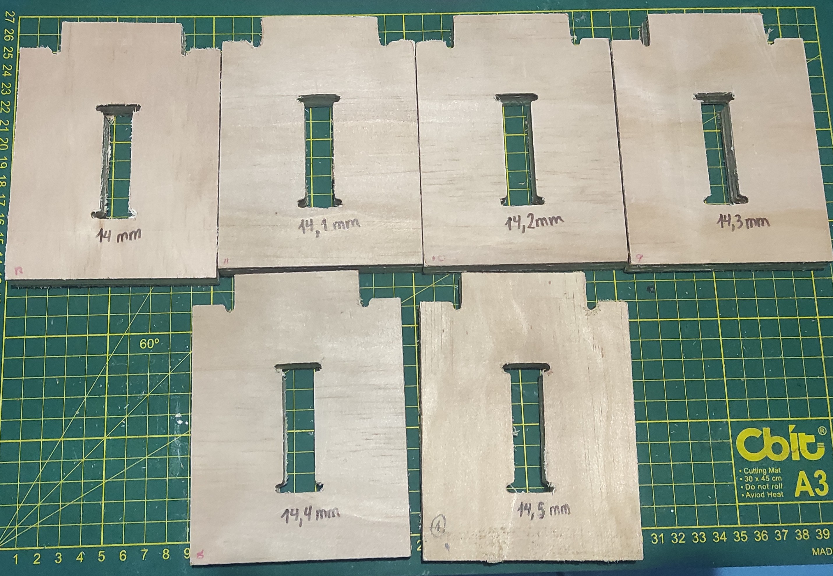
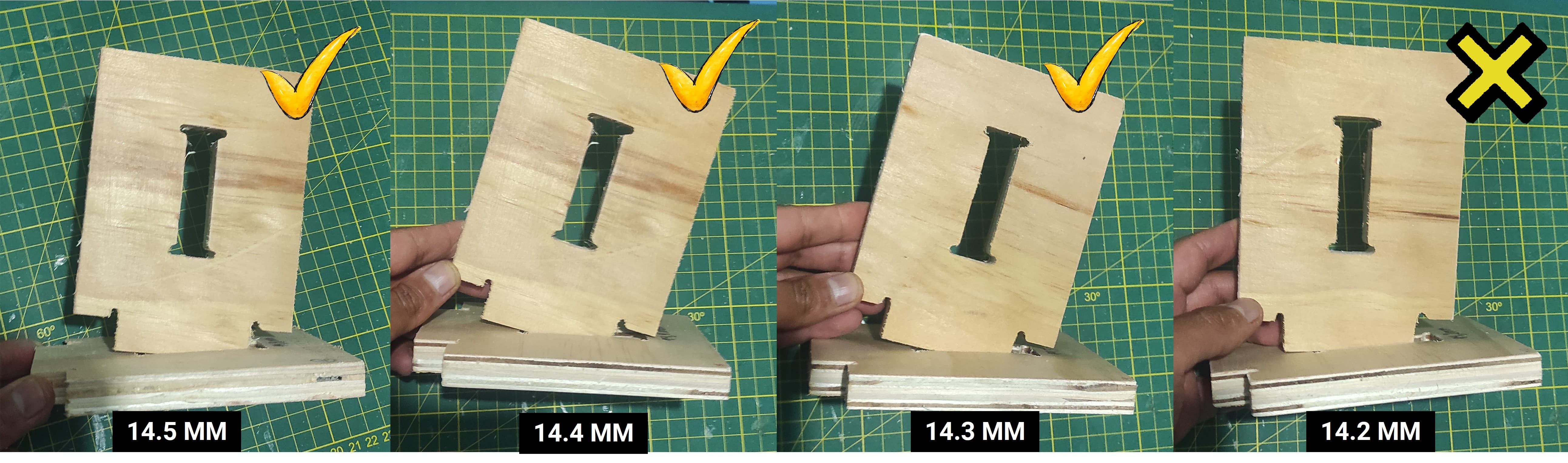
After reviewing the test cuts, I identified 14.3mm as the best fit. This size provided a snug connection without being too loose, ensuring the joints hold firmly during assembly.
Individual Assignment
4. CNC in Practice: Design / Mill / Assemble
4.1 Design Process
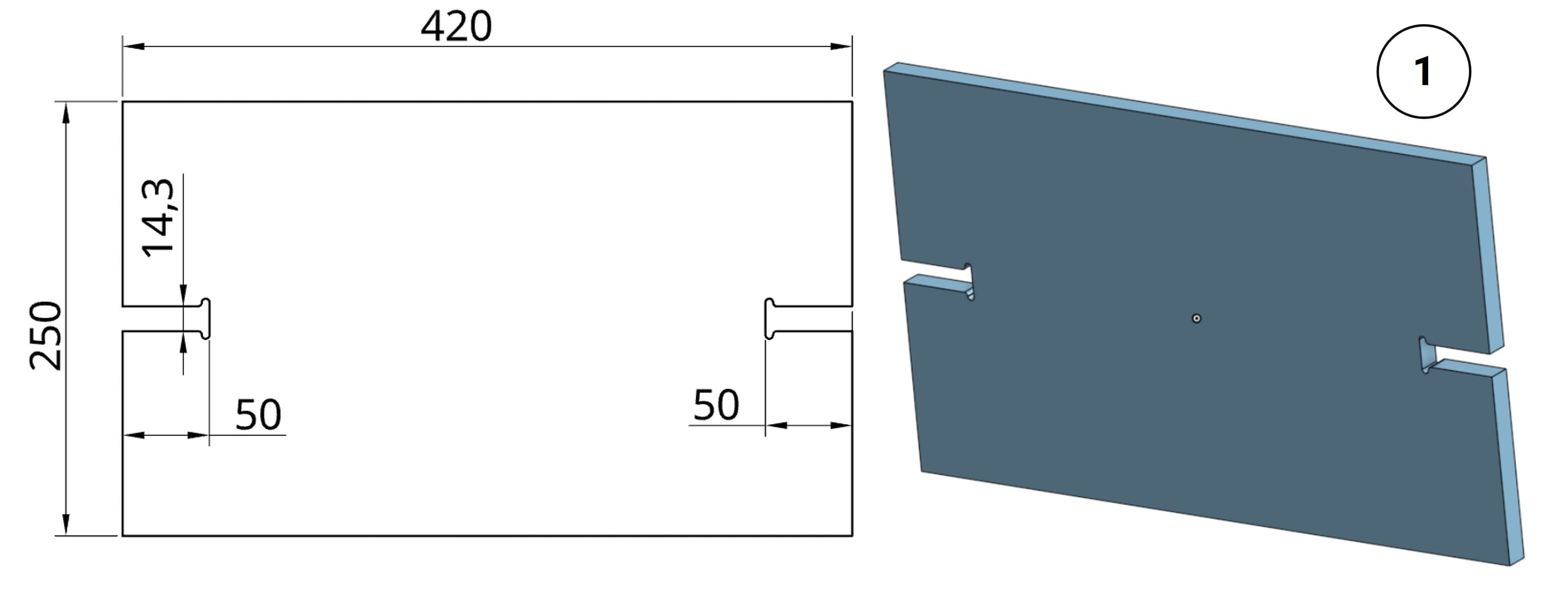
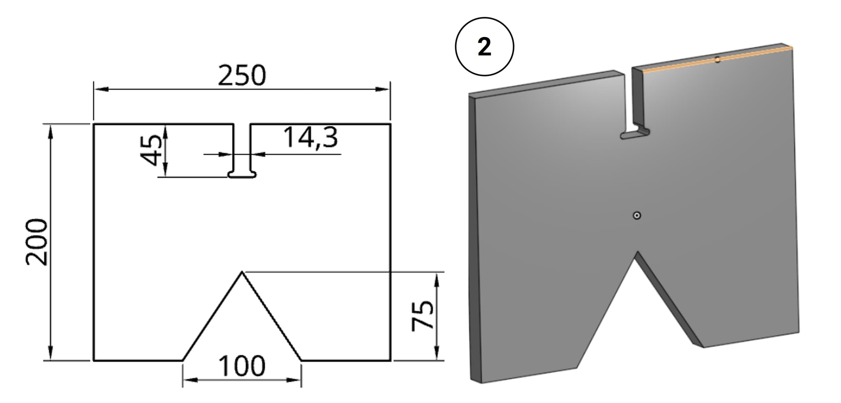
For the design of the plywood table I am planning to make, I used Onshape, which is a web-based software.
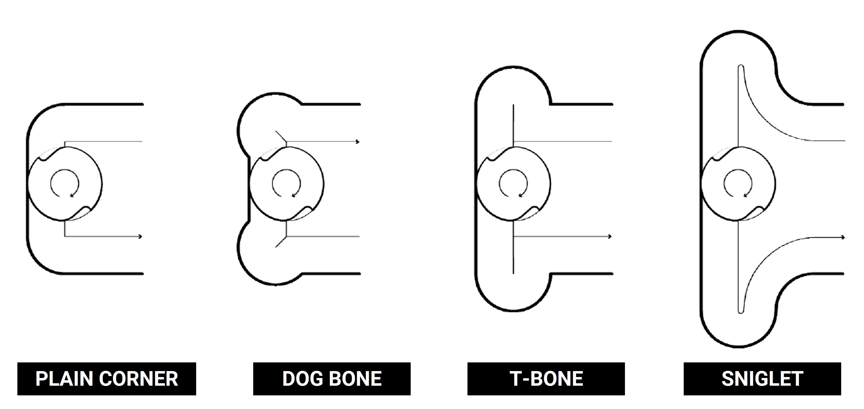
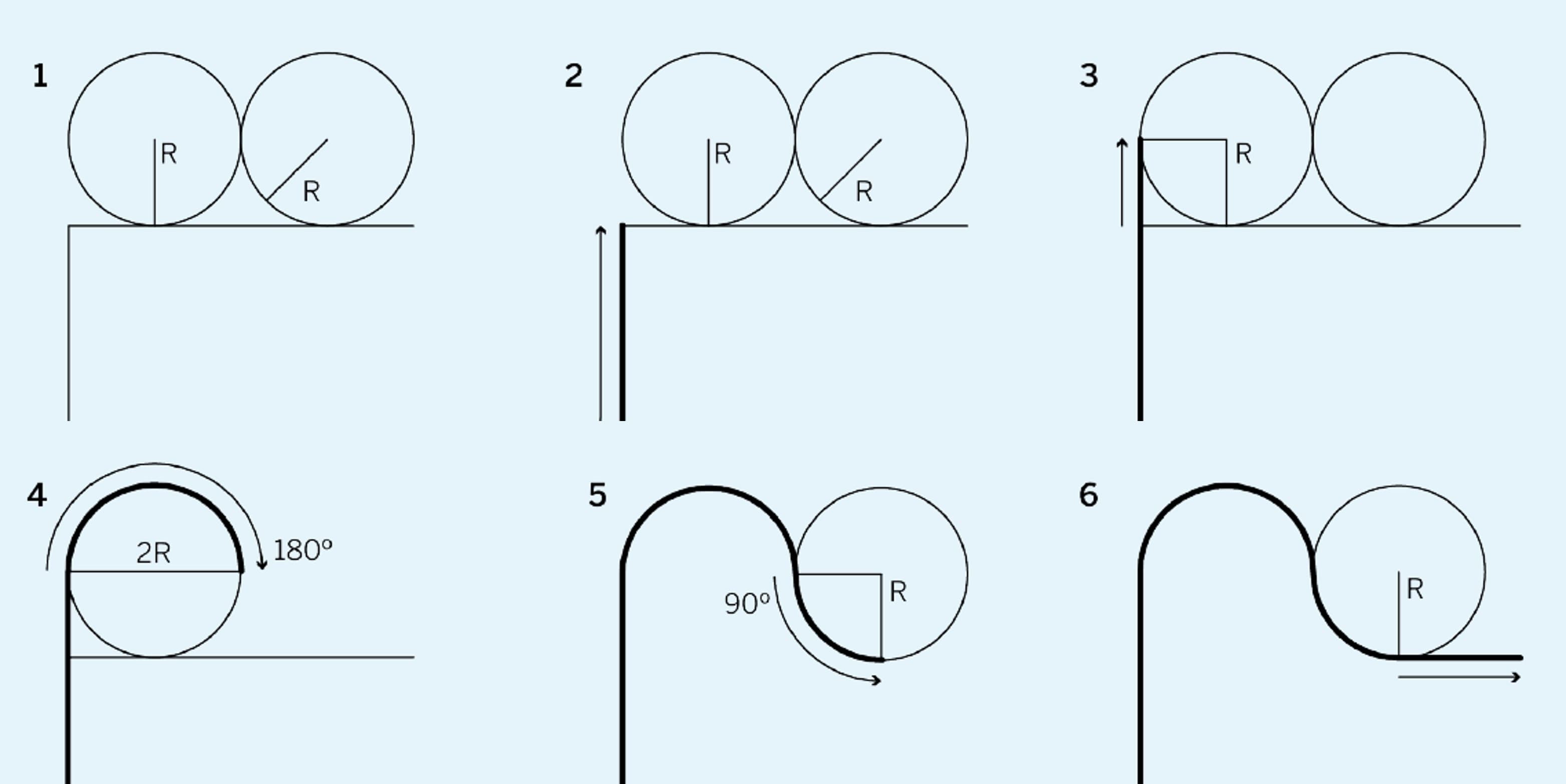
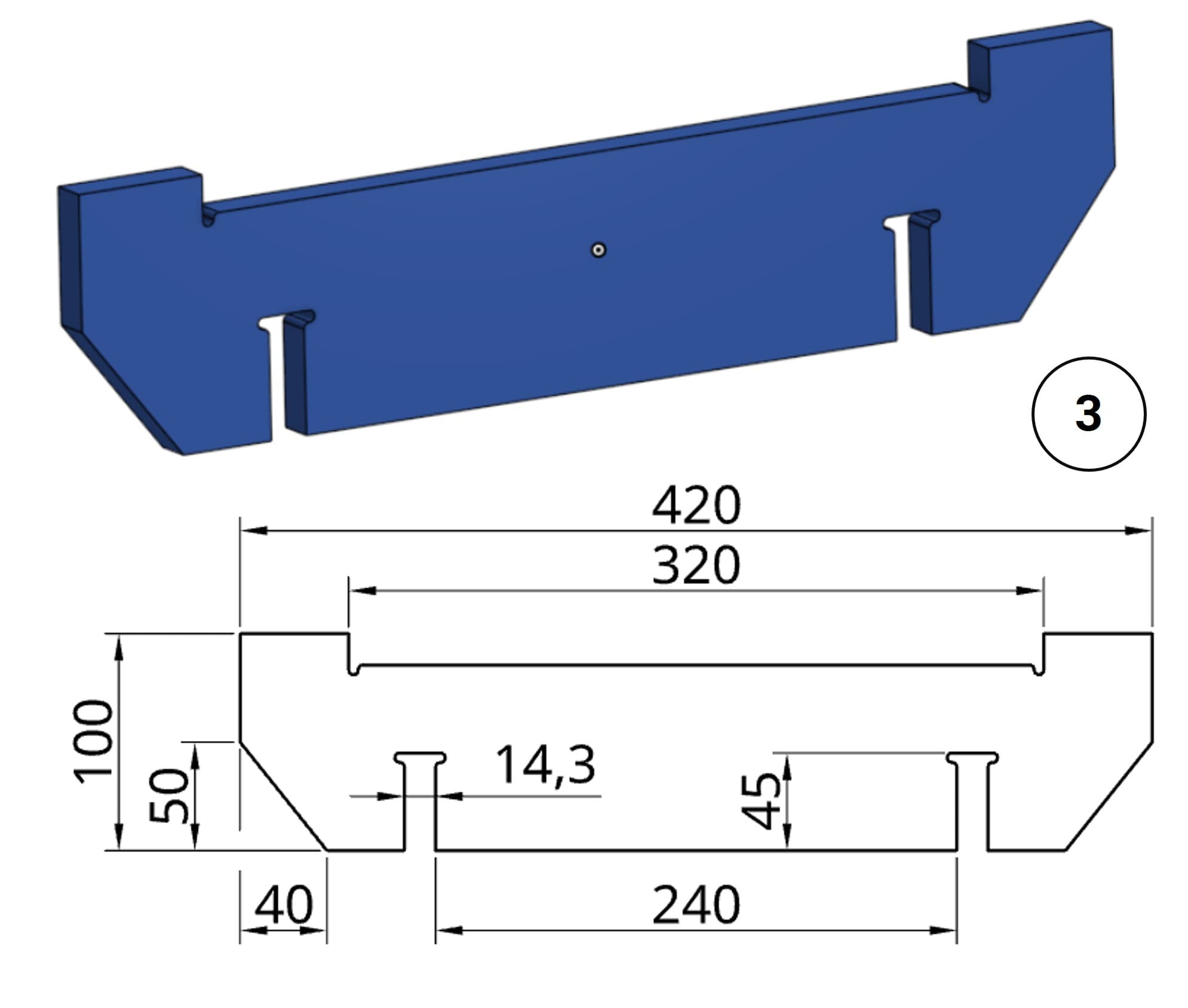
For the slots, I decided to use a sniglet design. Unlike dogbone or T-bone fillets, the sniglet features a continuous, radiused toolpath that allows the CNC tool to maintain momentum as it navigates each corner, resulting in a smoother cut and improved efficiency.
I am using 14.5mm plywood with a 4mm endmill. Therefore, the radius for the sniglet slots must be set to 110% of the tool diameter, which calculates to 4.4mm. This clearance ensures the corners are fully seated during assembly.
4.2 CNC Programming Process
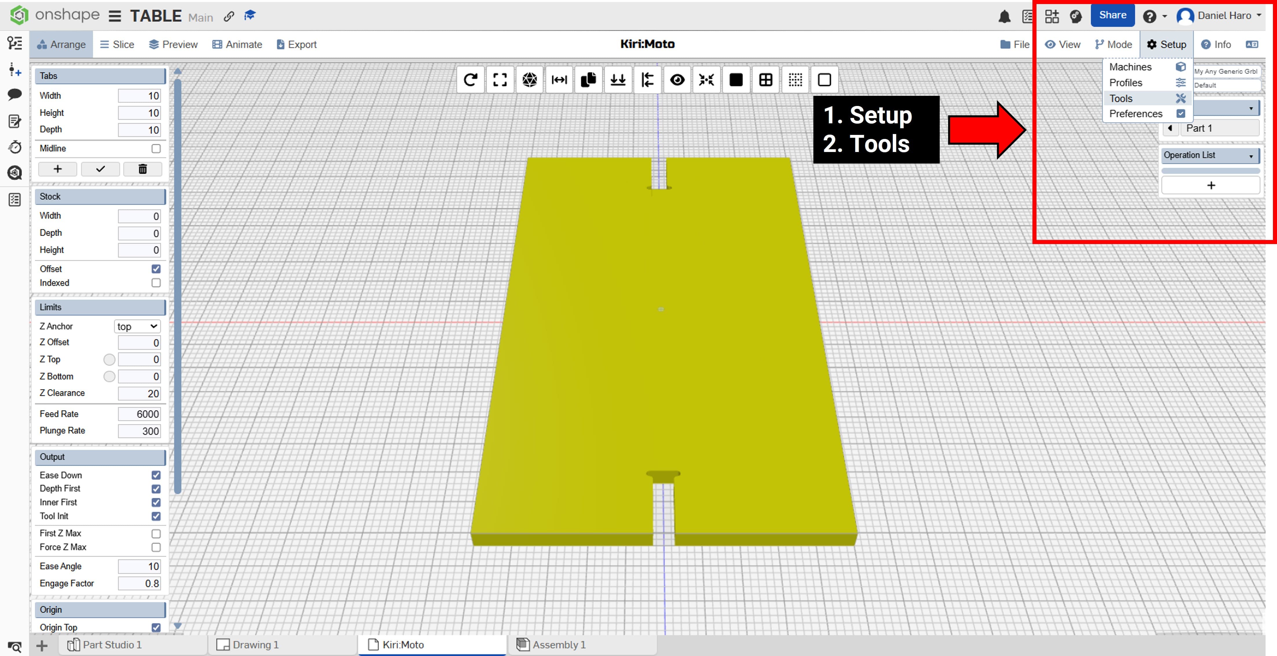
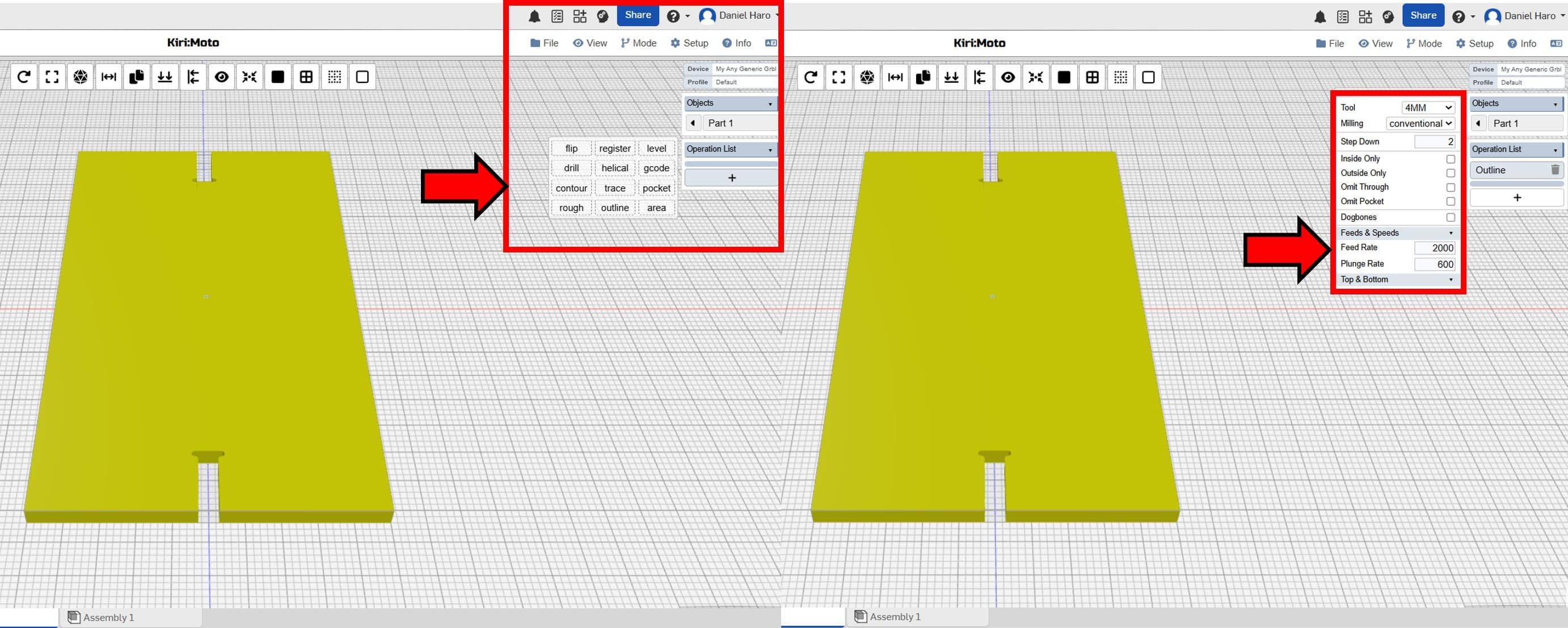
Once the parts have been designed, the next step is to import them into Kiri:Moto. After the file has been successfully imported, you must configure the tool settings, selecting the appropriate bit for the operation.
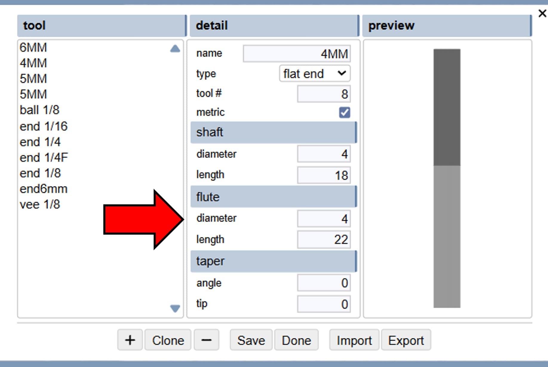
The tool selected for this job is a 4mm endmill. Its specific dimensions are listed below for reference. Diameter: 4mm, Length: 40mm and Flute: 22mm
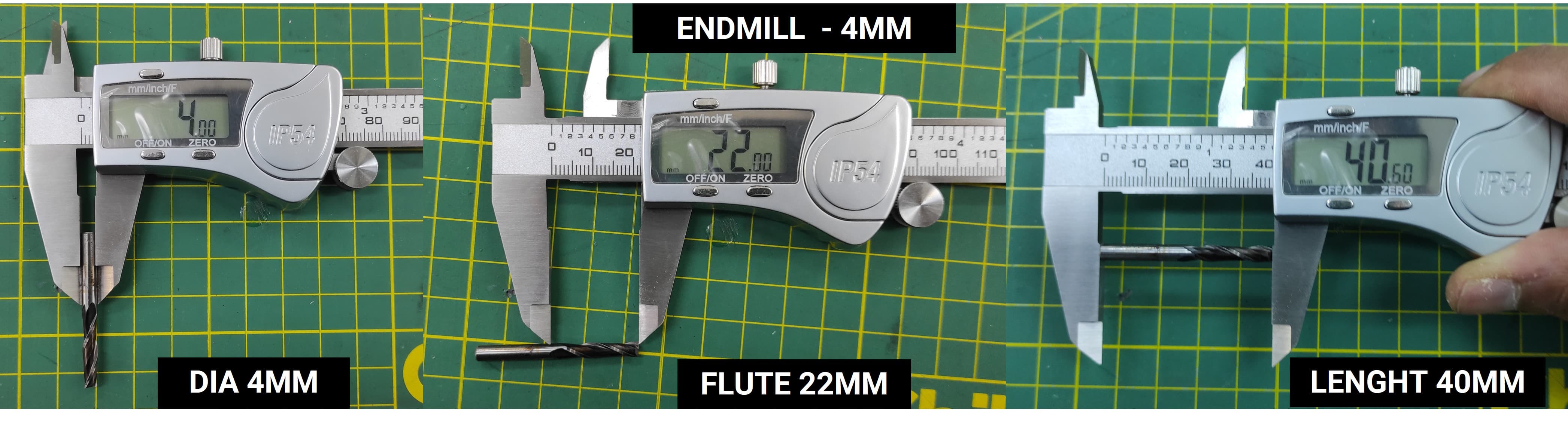
These dimensions are required to accurately configure the tool settings within Kiri:Moto. Entering the correct values ensures the toolpath is calculated correctly for a precise cut.
I used the configuration settings below for the CNC work.
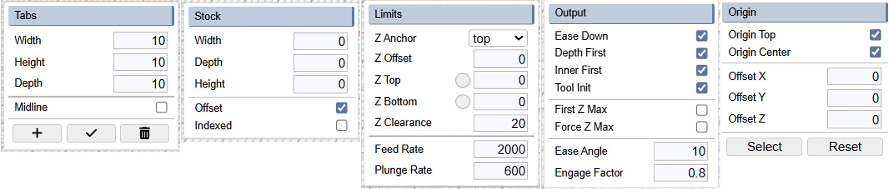
The next step is to configure the CNC job. We will select an Outline operation, which tells the machine to cut along the border of the part. Use the settings below for this job:
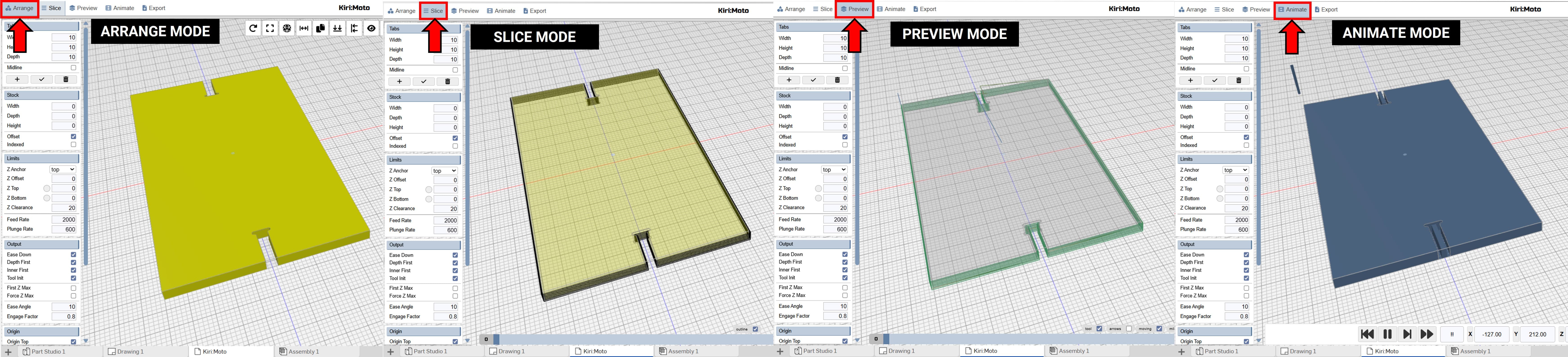
We can observe the process by switching from Arrange Mode to Animation Mode. This allows us to visualize exactly how the CNC machine will operate.
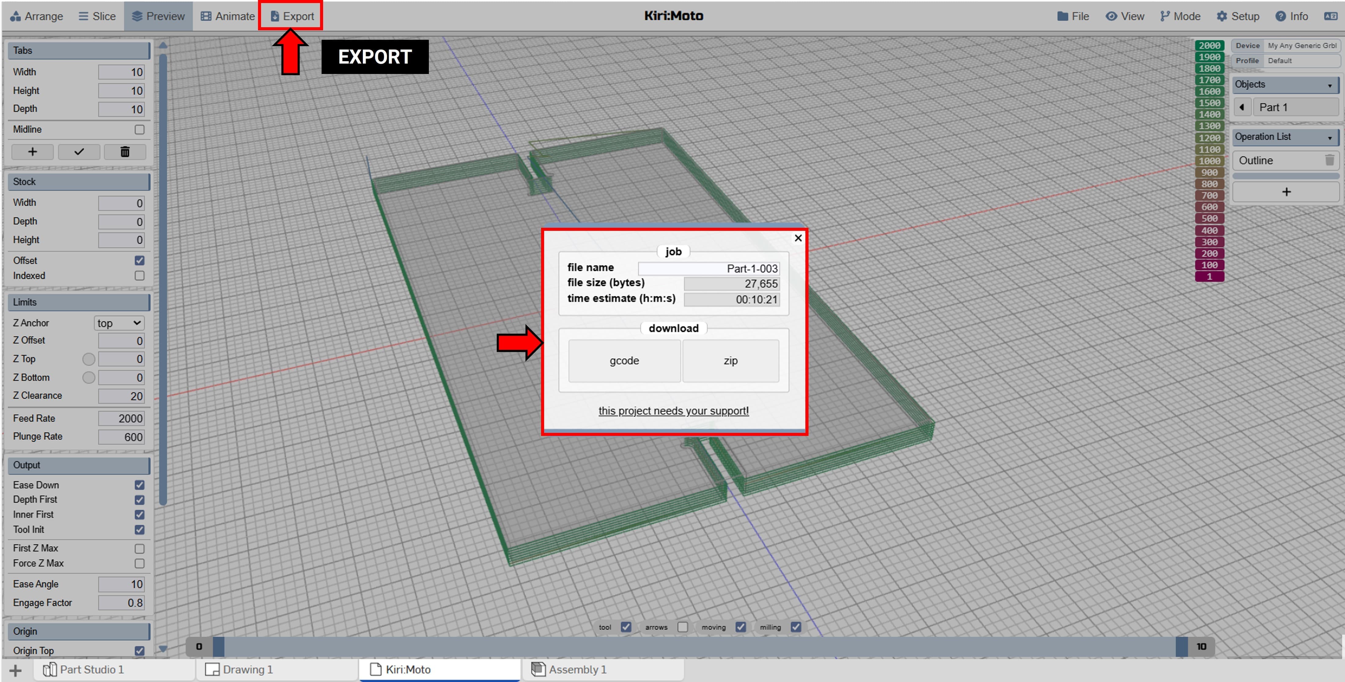
Finally, we need to export the completed CNC job as G-code. Once the file is generated, we are ready to move to the CNC router for fabrication. This file contains all the instructions the machine needs to cut the parts precisely as designed.
Shown below are the simulations for each individual part.
4.3 Fabrication Process
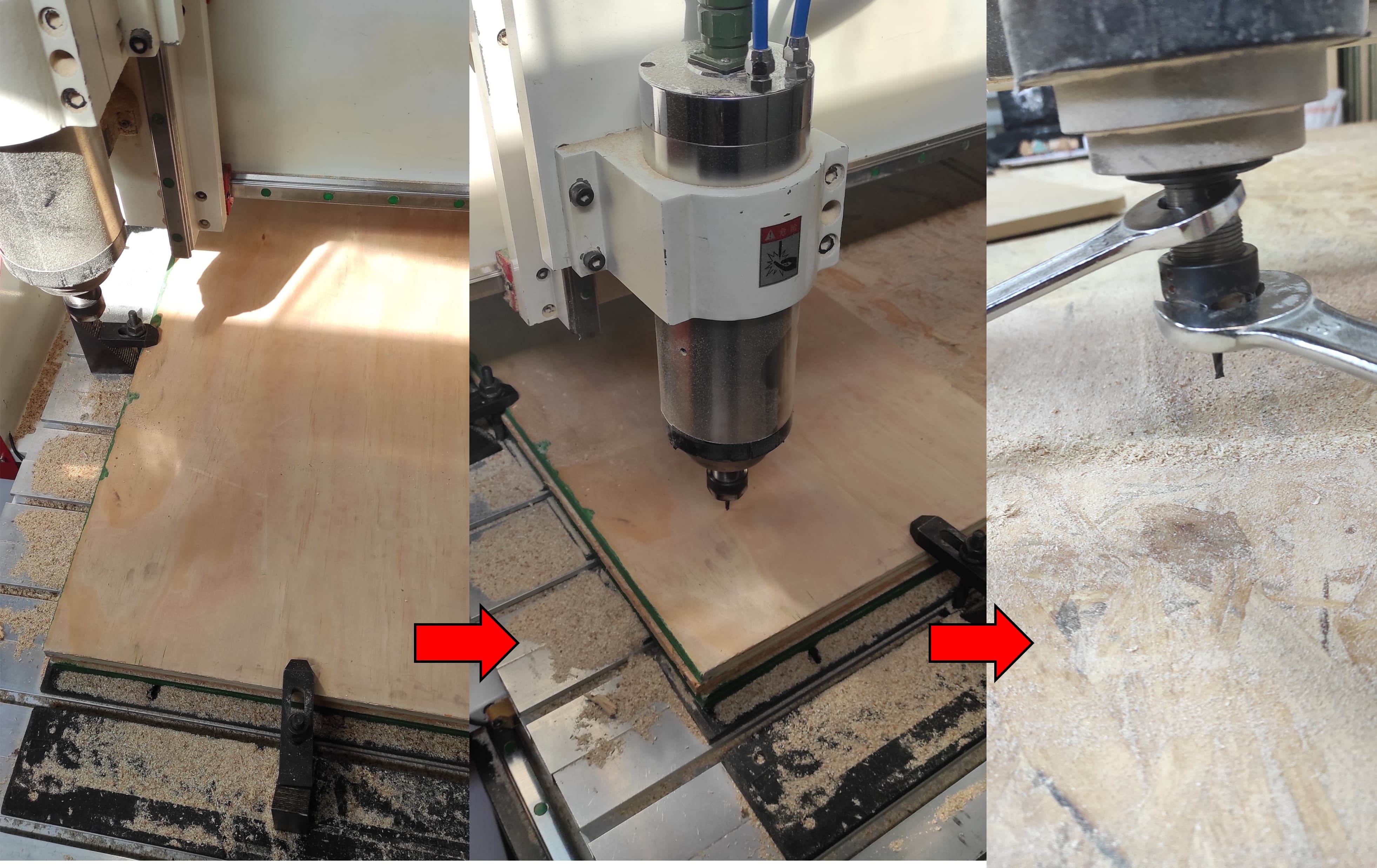
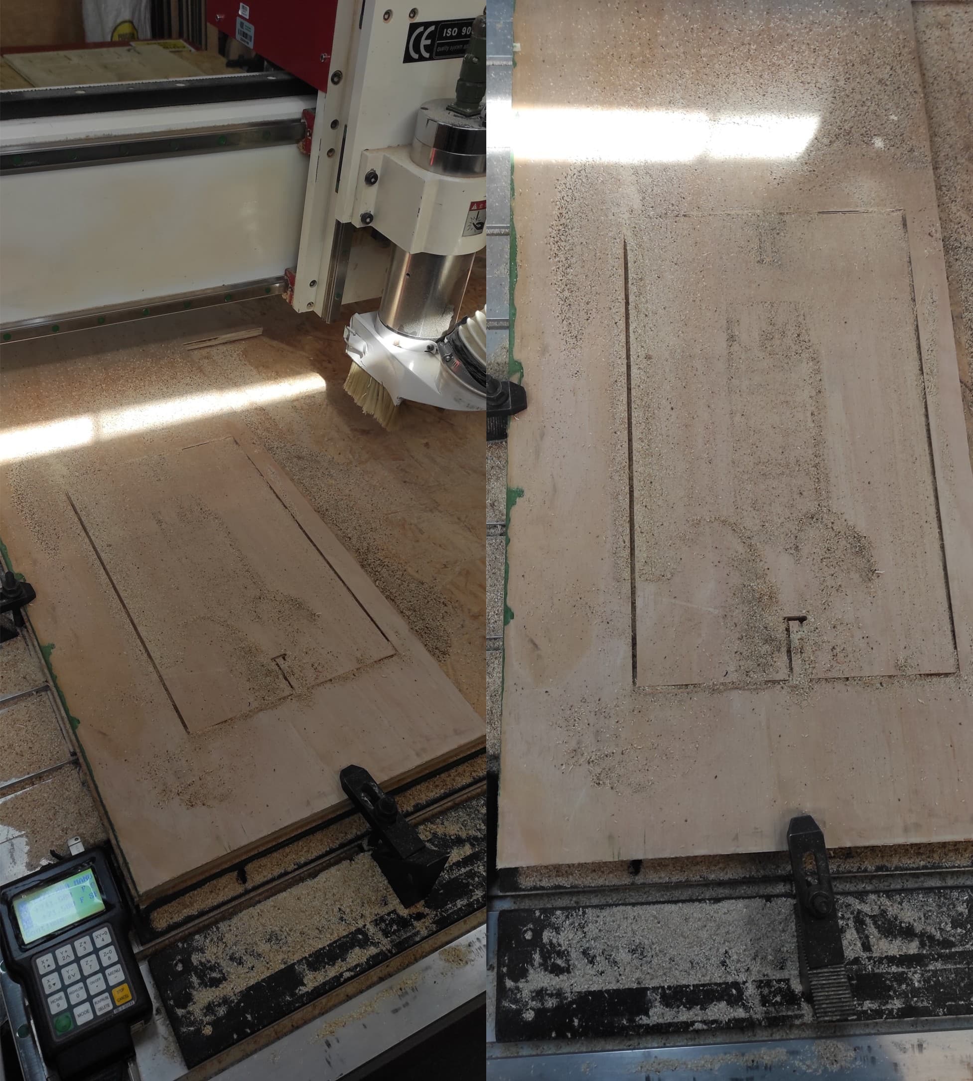
I then placed the 14.5mm plywood on the CNC router and clamped it in place. After installing the 4mm endmill, I set the origin (zero point) where the job would begin.
To set the new home position, first place the tool at the desired X, Y, and Z coordinates. Once the tool is in the correct position, use the DSP control to define the home position: press button 4 to set the X and Y home coordinates, and press button 8 to set the Z home coordinate.
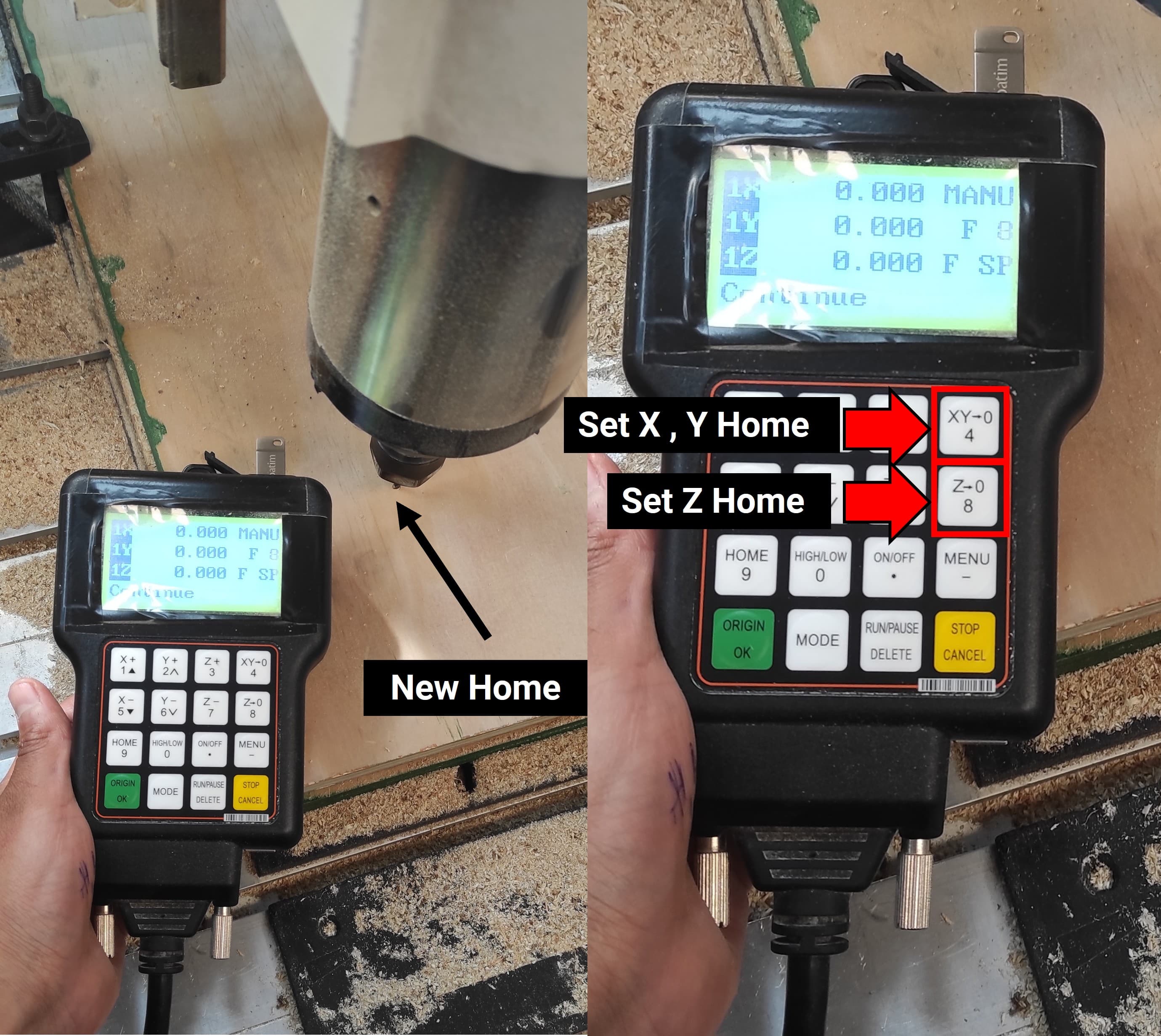
After that, I set the new home position on the RichAuto DSP controller to begin the work.
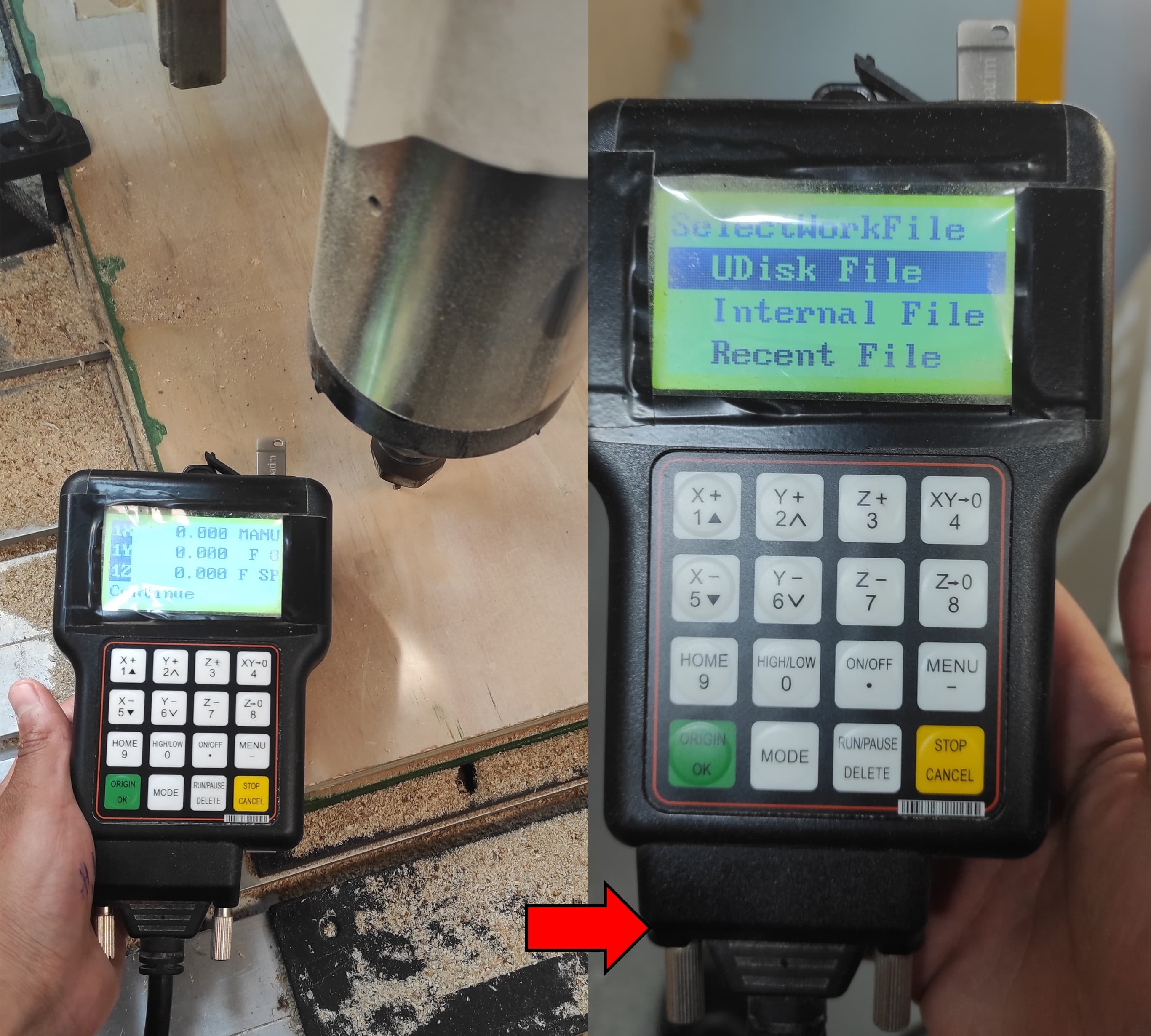
"After setting the home position, navigate to the file by following these steps on the controller: Go to UDiskFile -> Choose Select File -> WorkSpd to 2000 mm/min and FastSpd to 4000 mm/min -> Press OK to begin."
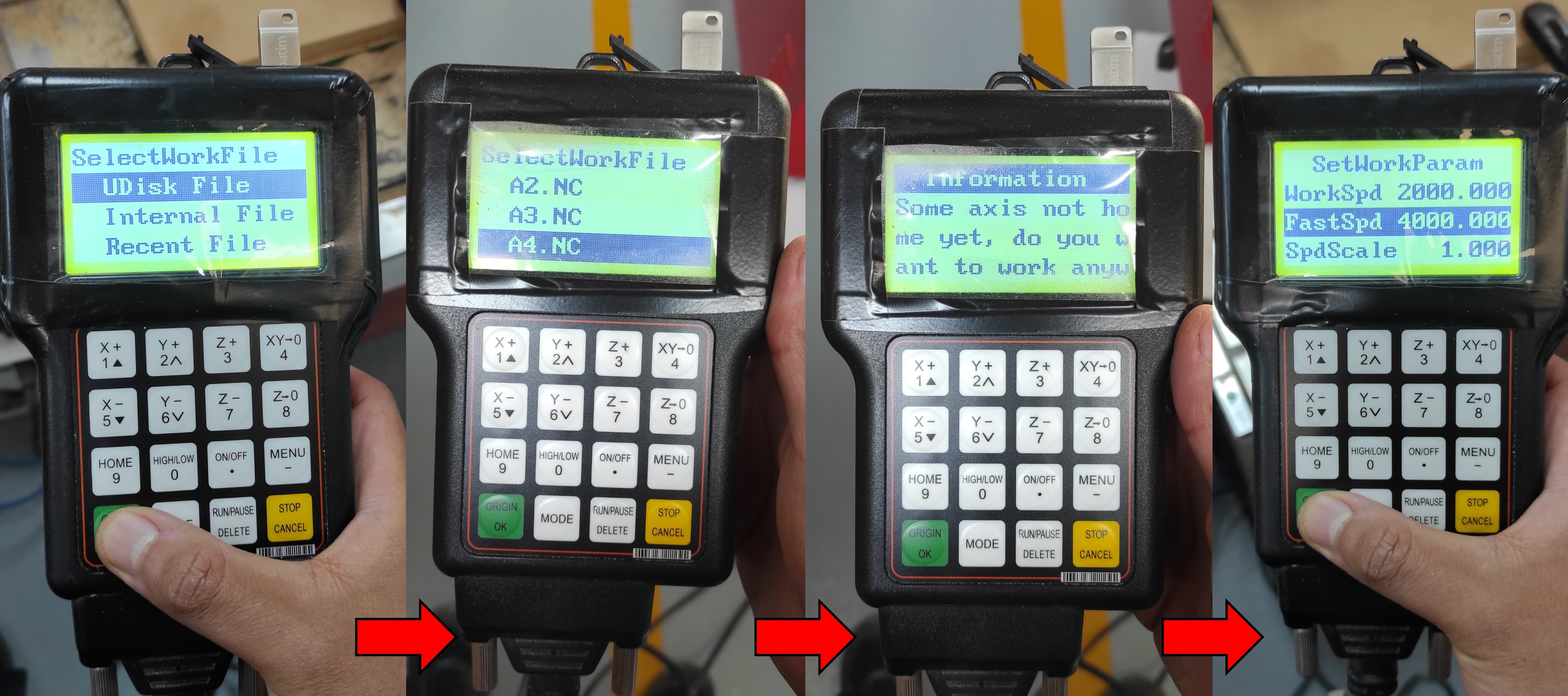
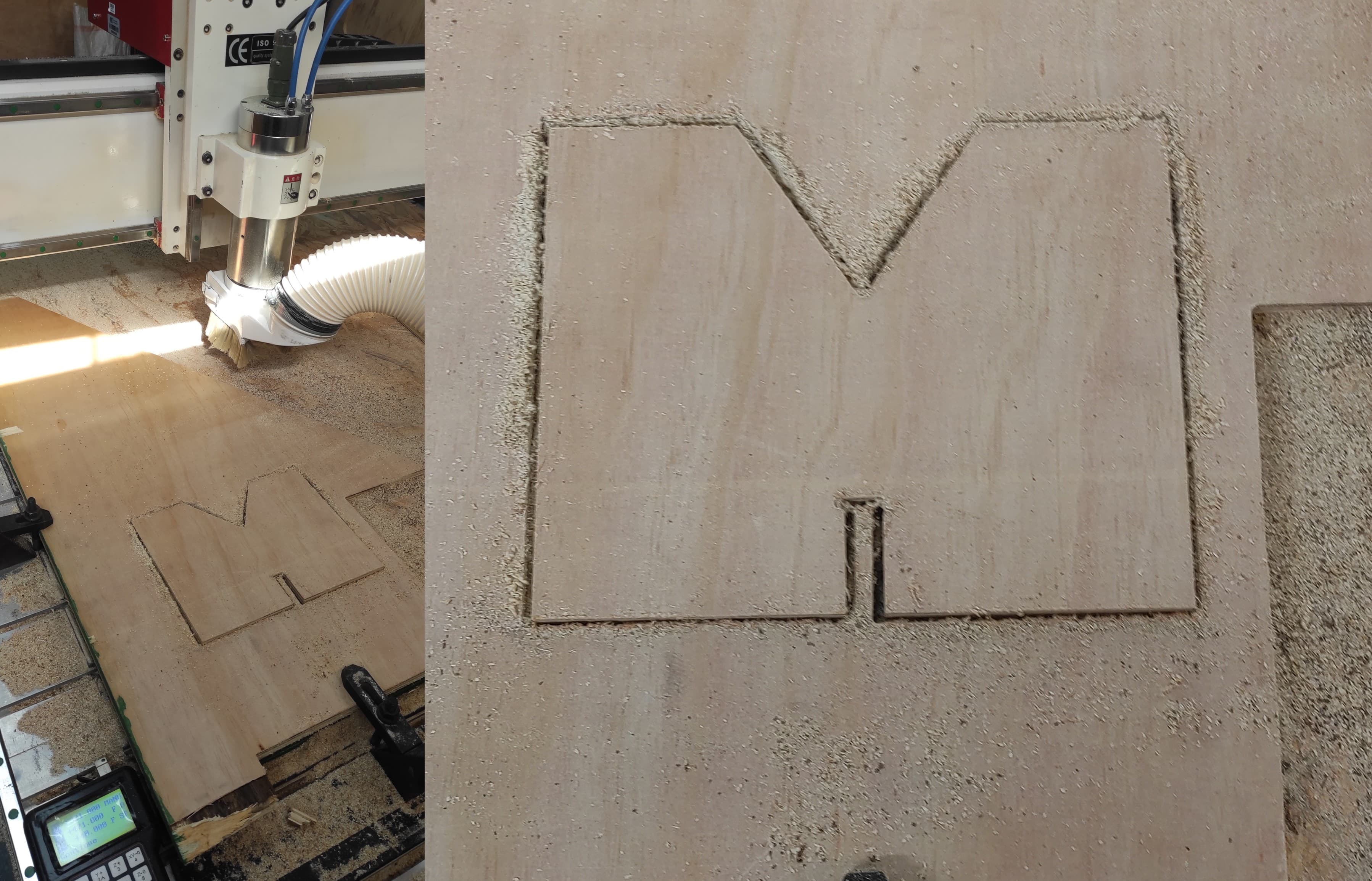
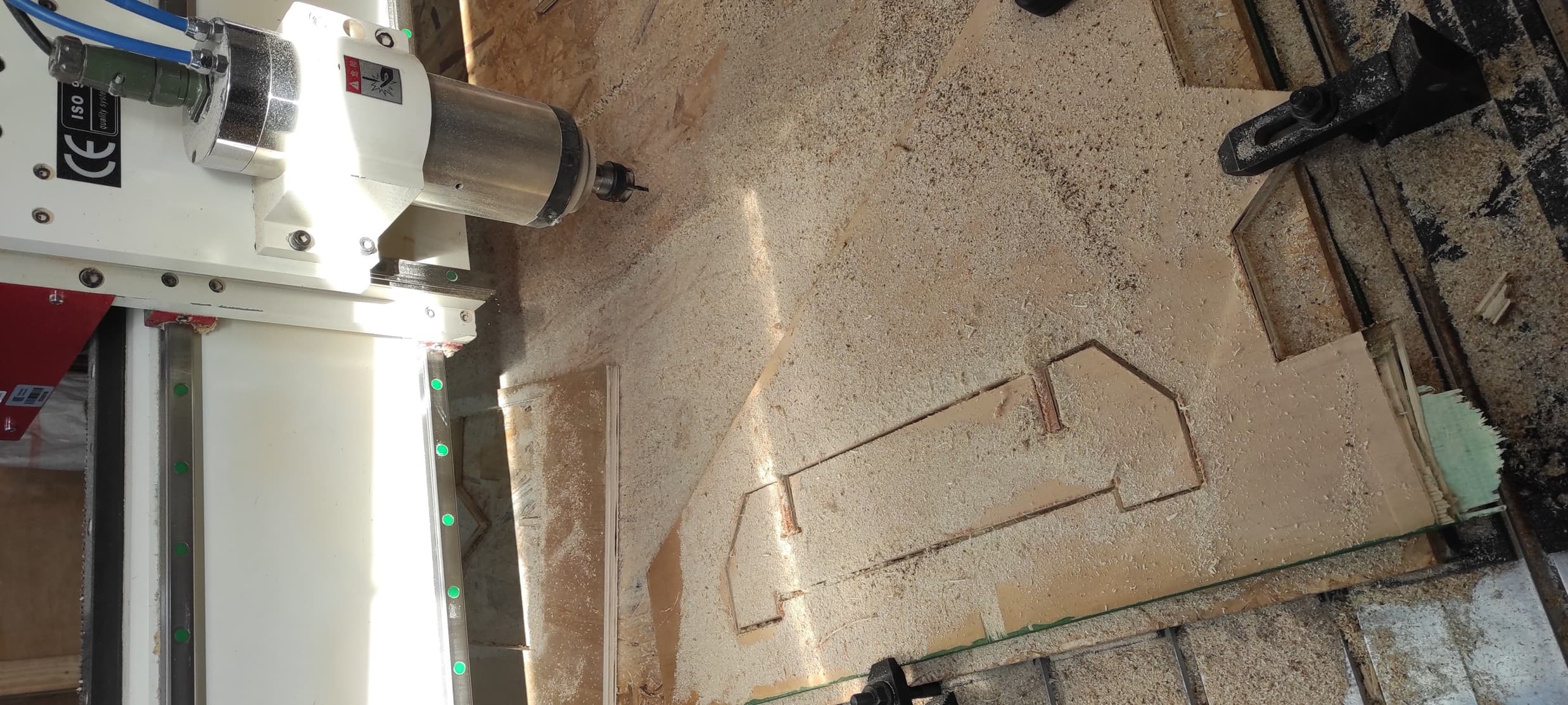
By selecting and running each G-code file individually, all parts were successfully machined on the CNC router.
4.4 Assembly Process
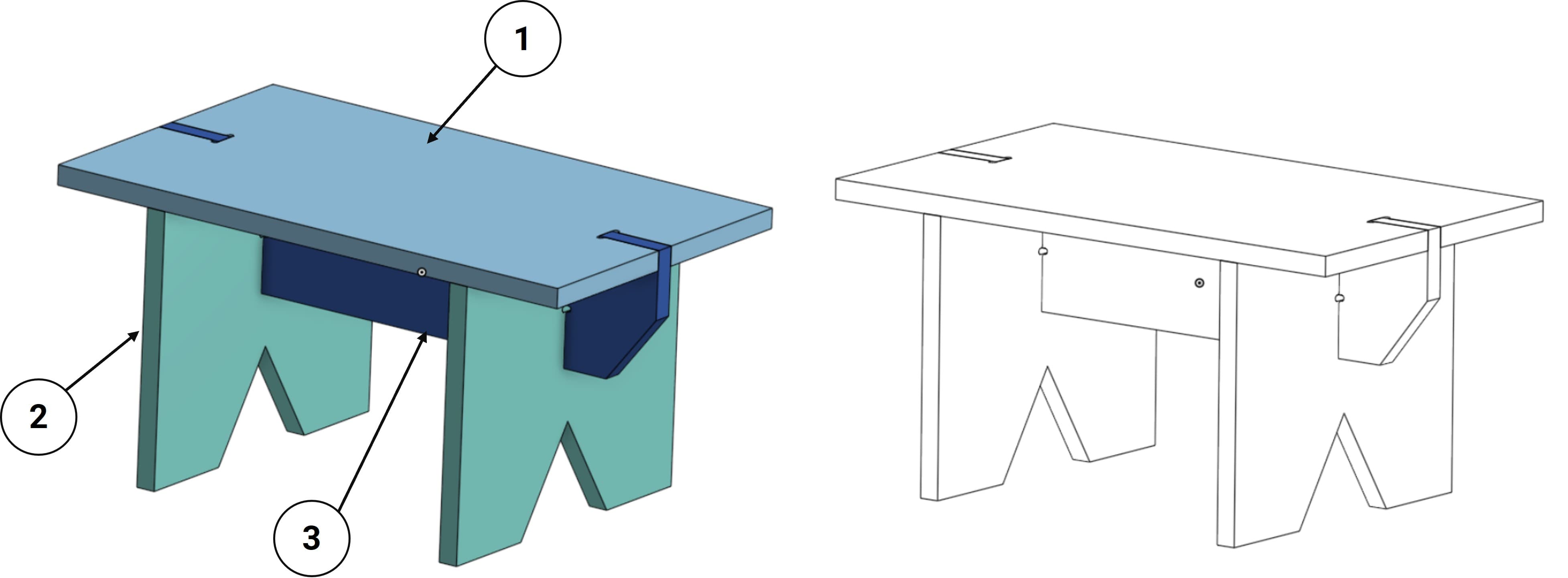
Once the pieces have been cut on the CNC router, they are ready for assembly. As shown in the image below, there are four pieces in total.
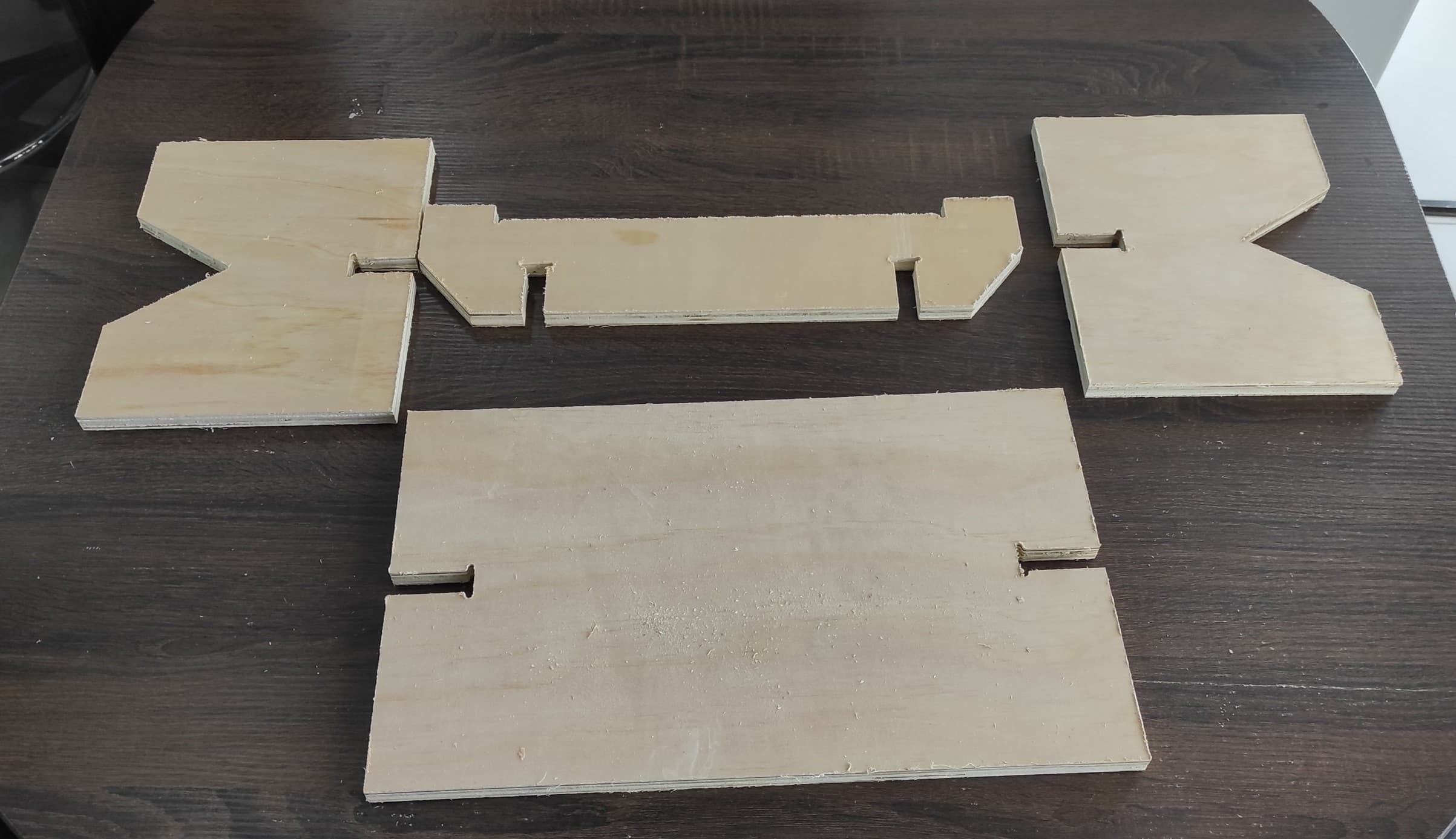
Before assembling them, we need to sand the pieces to ensure a good final fit. We must also wear gloves to protect ourselves.
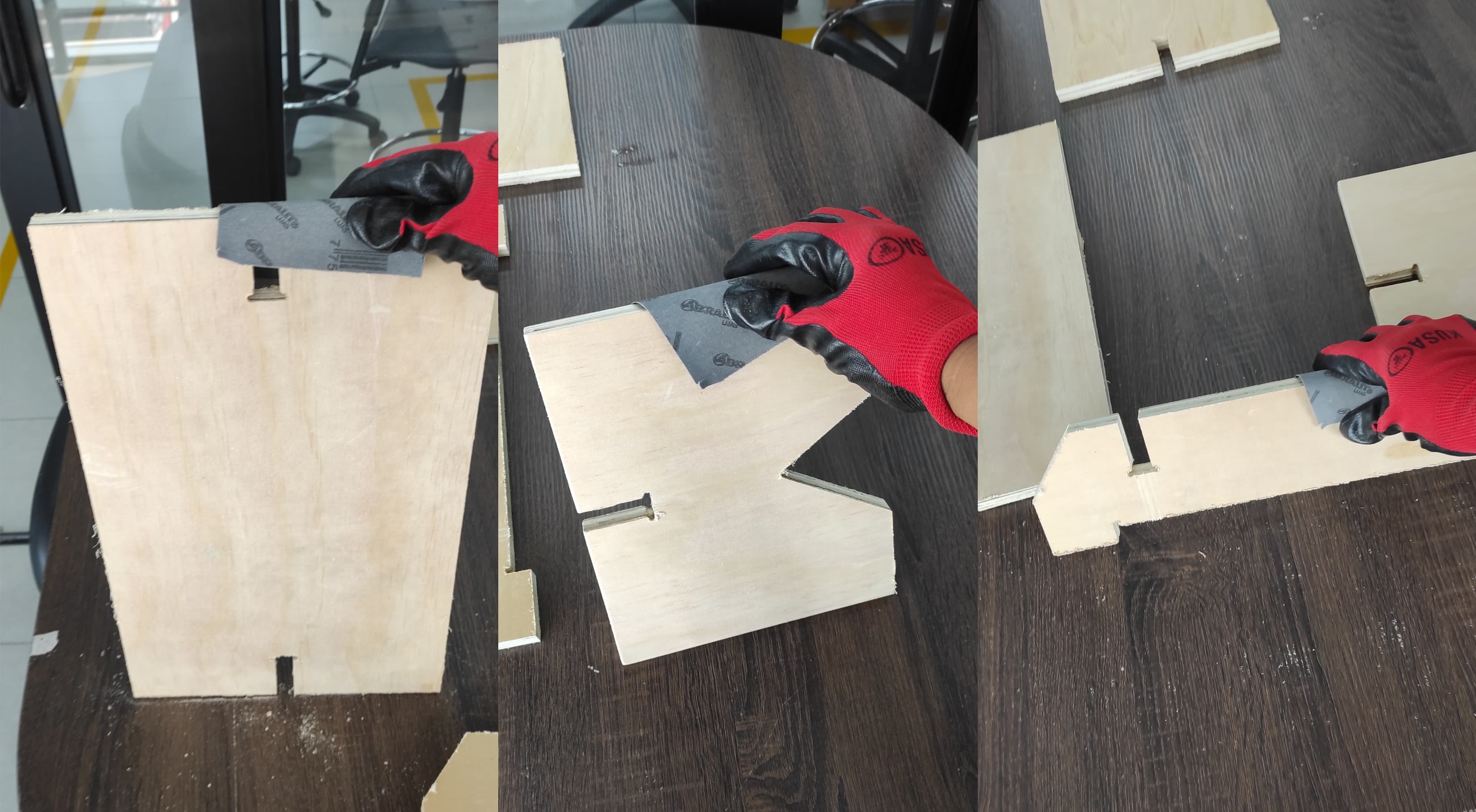
Using a plastic mallet or rubber hammer, gently tap the pieces together until the joints are fully seated. Avoid using a metal hammer, as this could damage the edges of the wood.
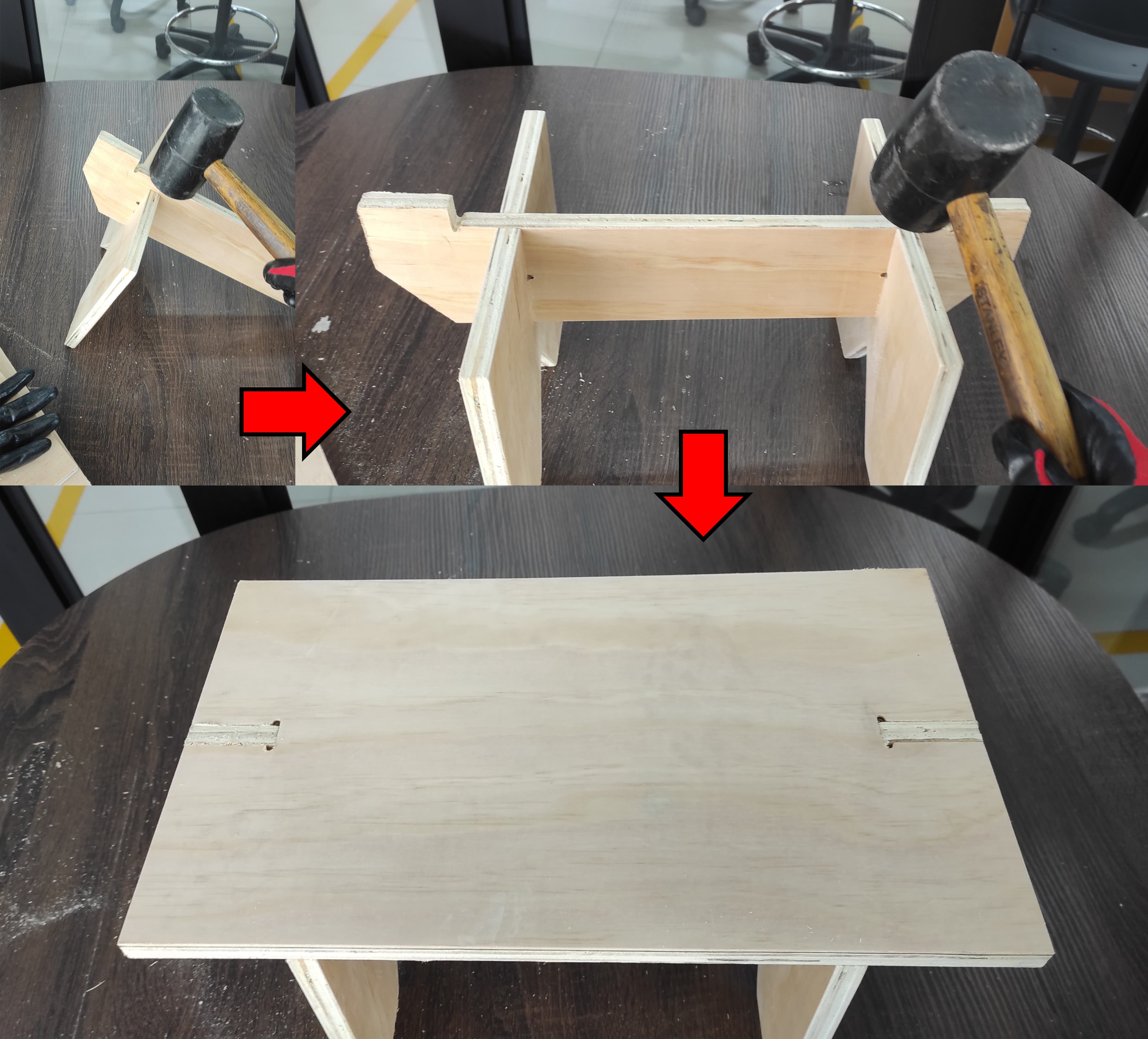
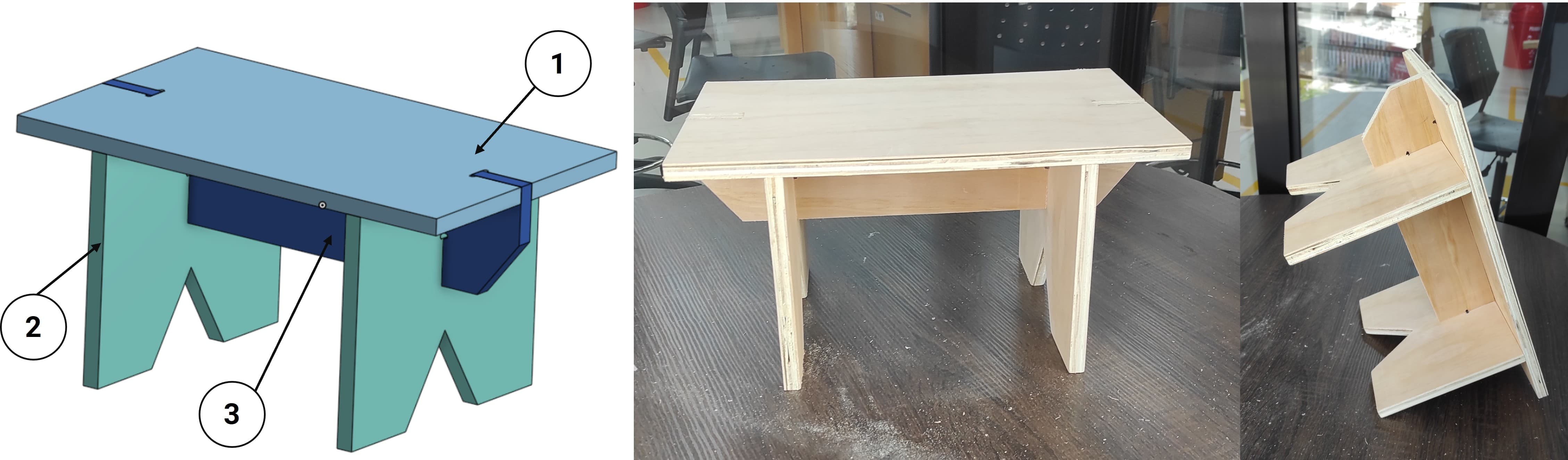
The assembly is now complete. It is perfectly firm, stable, and ready to use.
5. Learnings
To build on the excellent work you've documented, I recommend deepening your knowledge in three key areas: First, master parametric design in Onshape by learning to use variables and equations—this would allow you to change one dimension (like material thickness) and have all related features (slots, tabs, and sniglet radii) update automatically, saving time and reducing errors. Second, study feeds and speeds optimization for plywood by researching how spindle speed, feed rate, and depth of cut affect cut quality and tool life; using online calculators or manufacturer charts will help you dial in perfect settings for future projects. Third, expand your CAM knowledge beyond basic outlines by exploring advanced toolpath strategies like pocketing, adaptive clearing, and tabs, which will give you more control over complex parts. Finally, document your tolerance test results systematically—create a reference chart showing which slot clearances work best for different material thicknesses and tool sizes, turning your hands-on experiments into a reusable knowledge base for future plywood projects.
6. Files
Here are the files available for download.