Week 5 Progress Checklist
| Status | Task |
|---|---|
| ✓ | Linked to the group assignment page |
| ✓ | Explained what you learned from testing the 3D printers |
| ✓ | Documented how you designed and 3D printed your object and explained why it could not be easily made subtractively |
| ✓ | Documented how you scanned an object |
| ✓ | Included your original design files for 3D printing |
| ✓ | Included your hero shots |
3D Scanning and Printing
Group Assignment
3D Printing
1. Brief introdution
3D printing, also known as additive manufacturing, is the process of creating a physical, three-dimensional object from a digital design. Instead of carving away material from a block (like sculpting) or using a mold, a 3D printer builds the object layer by layer, from the bottom up. Think of it like a regular inkjet printer, but instead of depositing ink on paper, it deposits material—such as plastic, resin, or metal—to create a real object.
2. How Does It Work? (The Basic Process)
1. Design: It all starts with a 3D digital model, which is usually created with Computer-Aided Design (CAD) software or obtained from a 3D scan.
2. Slice: The printer software (a "slicer") cuts the digital model into hundreds or thousands of thin, horizontal layers. It generates a file (G-code) with the instructions for the printer.
3. Print The 3D printer follows these instructions, depositing or solidifying material layer by layer until the entire object is formed.
4. Finish: The printed object may need some post-processing, such as removing support structures, sanding, or painting.
3. 3D print - Bambulab Carbon X1C
The Bambu Lab X1 Carbon (X1C) is a high-speed, feature-rich 3D printer that has significantly impacted the market by blending industrial-grade performance with consumer-friendly usability . Launched in mid-2022, it's designed for enthusiasts and professionals who demand high-quality prints, speed, and the ability to work with advanced materials
Official Manufacturer: Bambulab Carbon X1C

| Bambu Lab X1 Carbon Complete Specifications | |||
|---|---|---|---|
| Category | Feature | Category | Feature |
| 📐 General | Technology: FDM Launch: June 2022 Structure: CoreXY Volume: 256mm³ Dimensions: 389×389×457mm Weight: 14.13kg |
🔥 Print Head | Extruder: Direct Drive Nozzle: Hardened steel 0.4mm Optional: 0.2/0.6/0.8mm Max Temp: 300°C Gear: Hardened Steel |
| 🛏️ Build Plate | Max Temp: 110°C/120°C Plates: Textured PEI, Cool, Engineering, High-Temp, SuperTack |
⚡ Speed | Max Speed: 500 mm/s Accel: 20,000 mm/s² Layer Height: 0.1mm Resolution: 0.1mm |
| 🧵 Filament | Ideal: PLA, PETG, TPU, PVA, PET Advanced: ABS, ASA, PA, PC Reinforced: Carbon/Glass Fiber |
🧠 Smart Features | Leveling: Dual Auto (Lidar+Force) Lidar: First-layer inspection AI: Spaghetti detection Camera: 1080p Runout Sensor: Yes Power Loss Recovery: Yes |
| 🖥️ Electronics | Display: 5" 1280x720 touch Connect: Wi-Fi, Bambu Bus, microSD Storage: 4GB eMMC + microSD CPU: Quad ARM A7 1.2GHz NPU: Yes for AI |
🔌 Electrical | Input: 100-240V 50/60Hz Max Power: 1000W@220V / 350W@110V Chamber: Up to 60°C Filtration: Active carbon Ambient: 10-30°C |
| 🎨 Multi-Color | AMS Support: Yes Max Colors: 16 (4 AMS units) |
📦 Package | X1C Size: 480×480×535mm X1C Weight: 18kg Combo Size: 480×480×590mm Combo Weight: 22.3kg (w/AMS) |
| 💻 Software | Slicer: Bambu Studio 3rd Party: Cura, PrusaSlicer, Orca, SuperSlicer (limited) App: Bambu Handy Offline: Yes (microSD) LAN Mode: Yes |
✅ Certifications | EU: CE-RED, CE-MD, RoHS, REACH, EN60825 US/CA: NRTL, FDA, FCC, IC UK: UKCA, PSTI AU: RCM JP: PSE, MIC KR: KC |
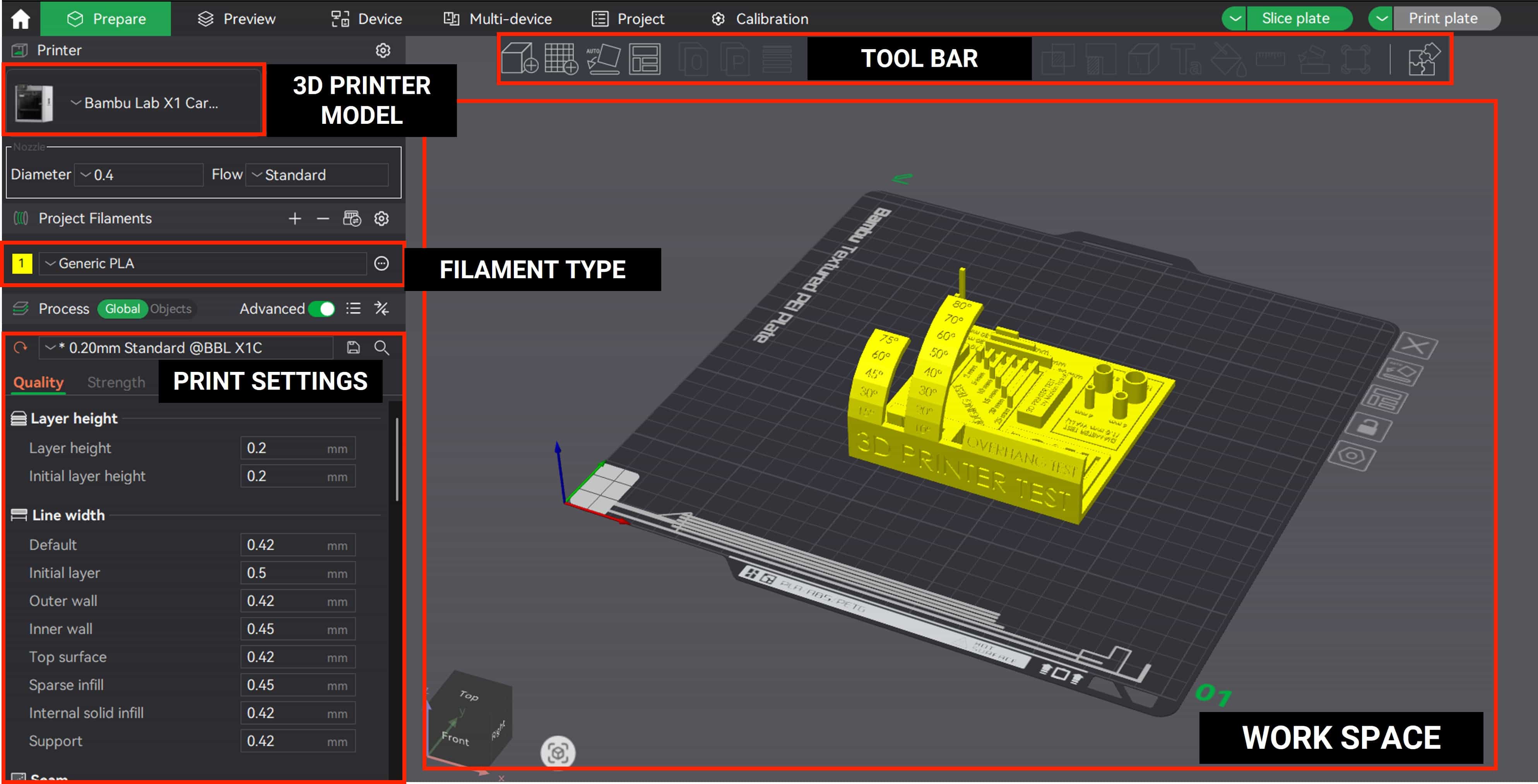
4. Bambu Studio
Bambu Studio is a free, open-source, and feature-rich slicing software developed by Bambu Lab . A slicer is an essential piece of software in FDM 3D printing that converts a 3D model (like an STL or STEP file) into G-code—a set of instructions that tells your printer exactly how to move, how much filament to extrude, and at what temperature to create your object layer by layer.
Download Software: Bambu Studio
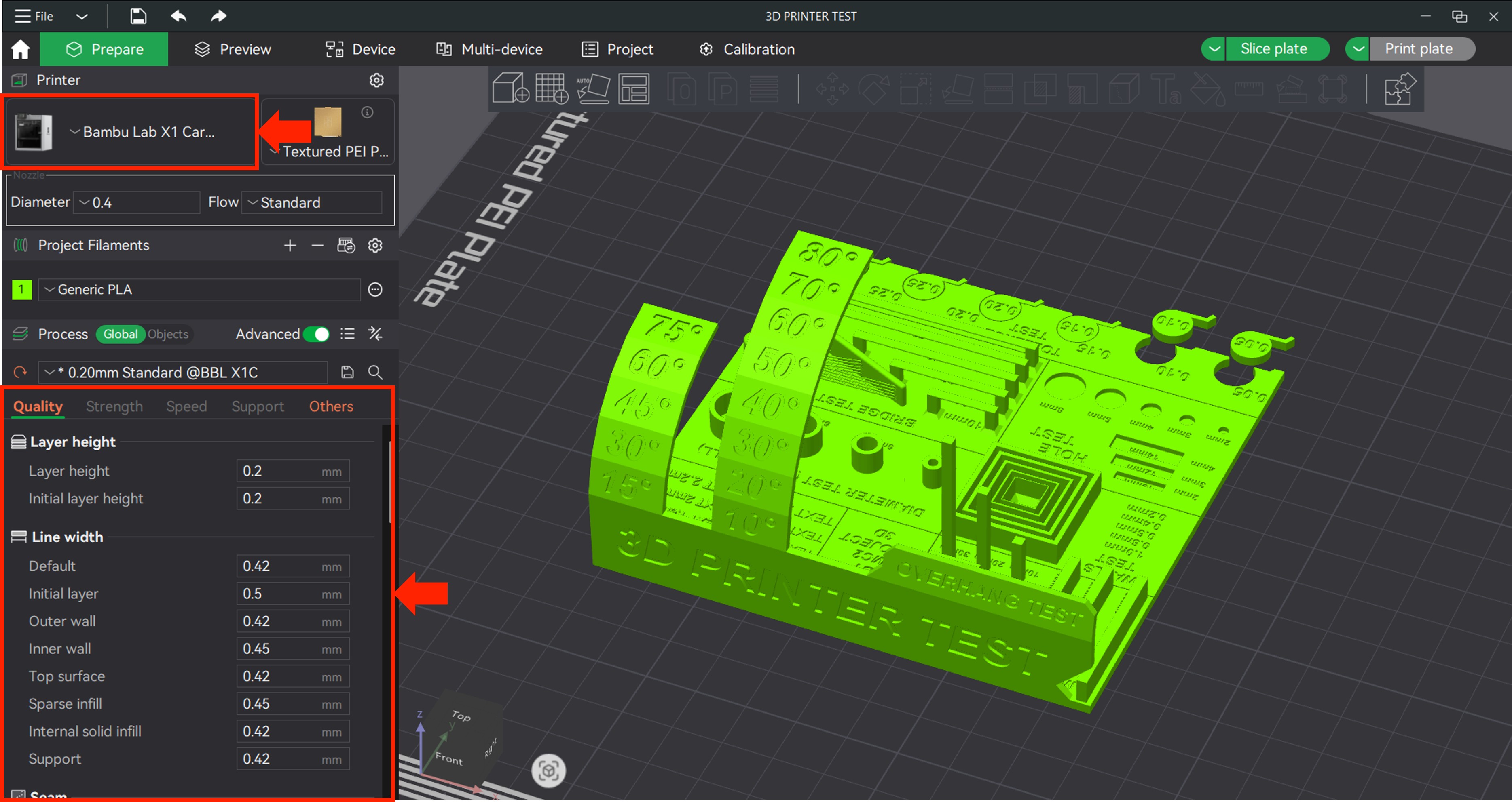
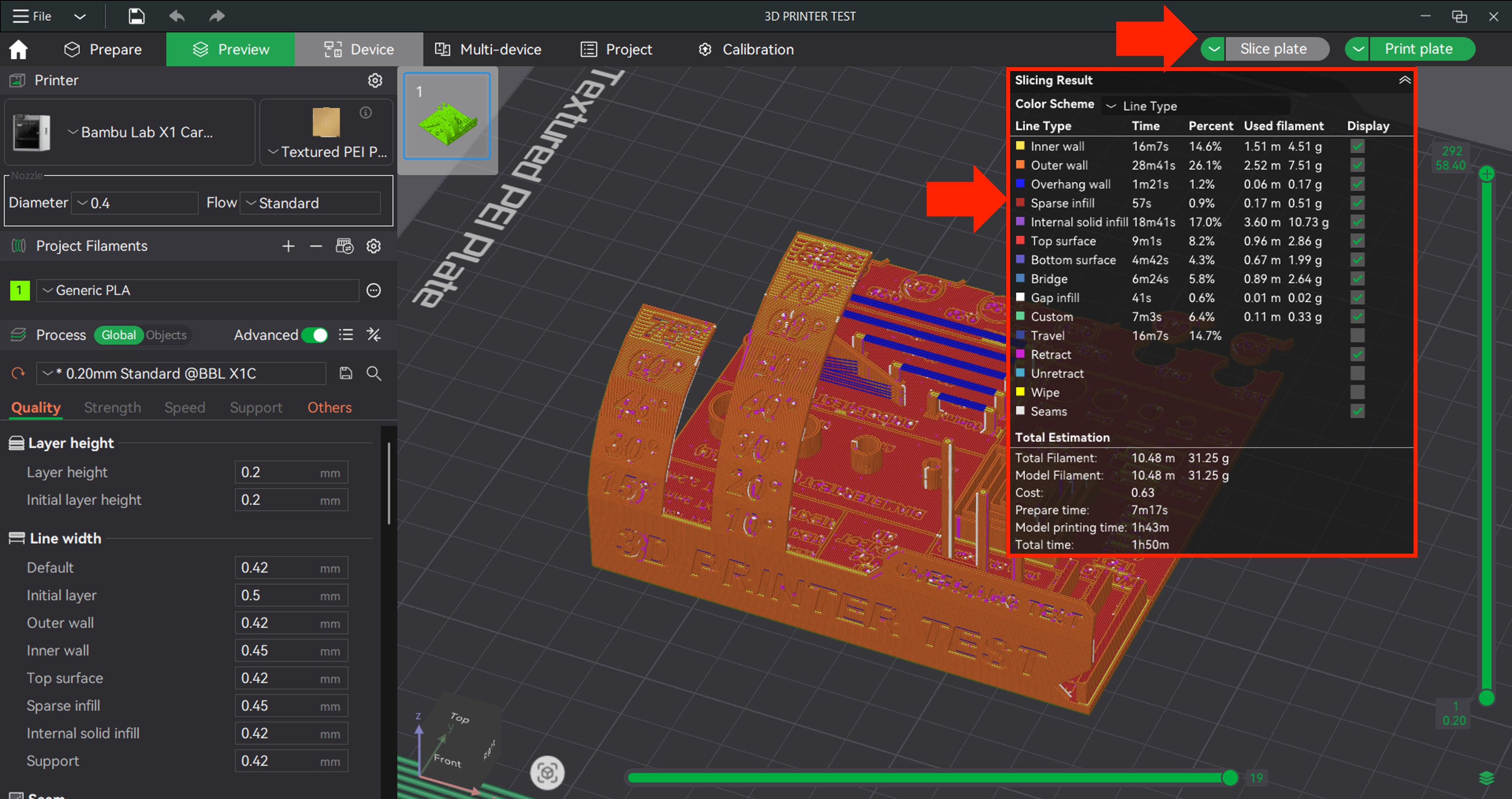
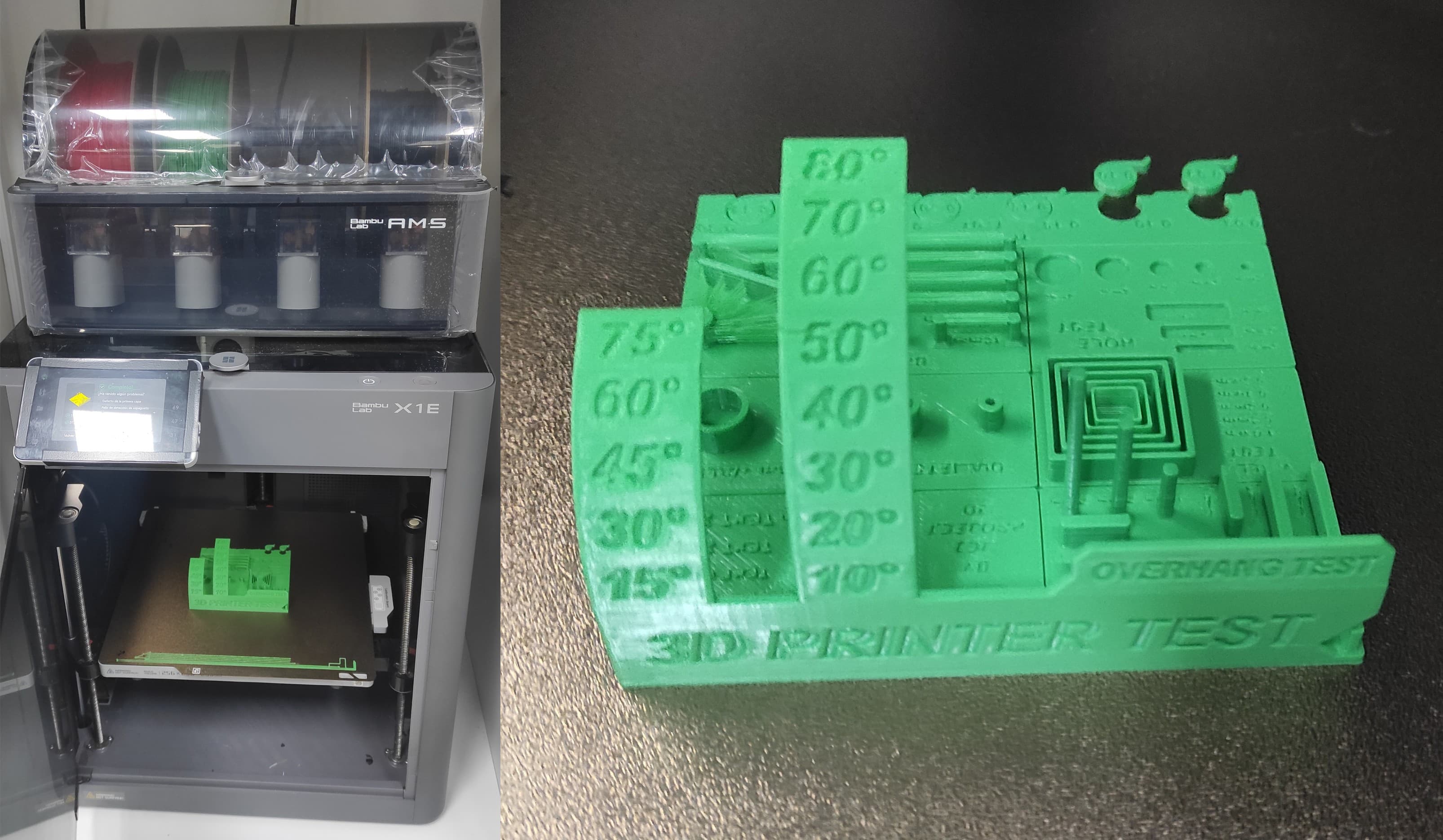
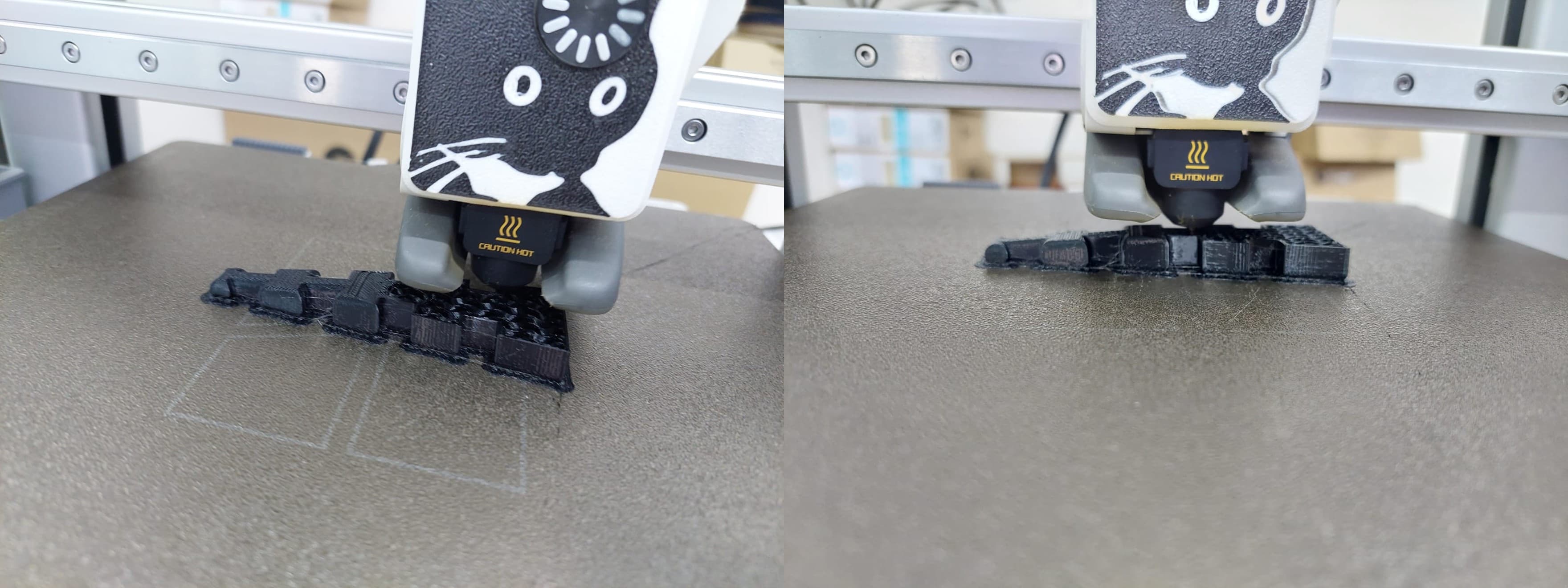
5. Printing Test
A printing test, often referred to as a test print, is a diagnostic procedure used to evaluate the performance and quality of a printer. By producing a sample page, users can check for common issues such as misalignment, color accuracy, resolution quality, and hardware functionality, ensuring the device is operating correctly before starting a full print job.
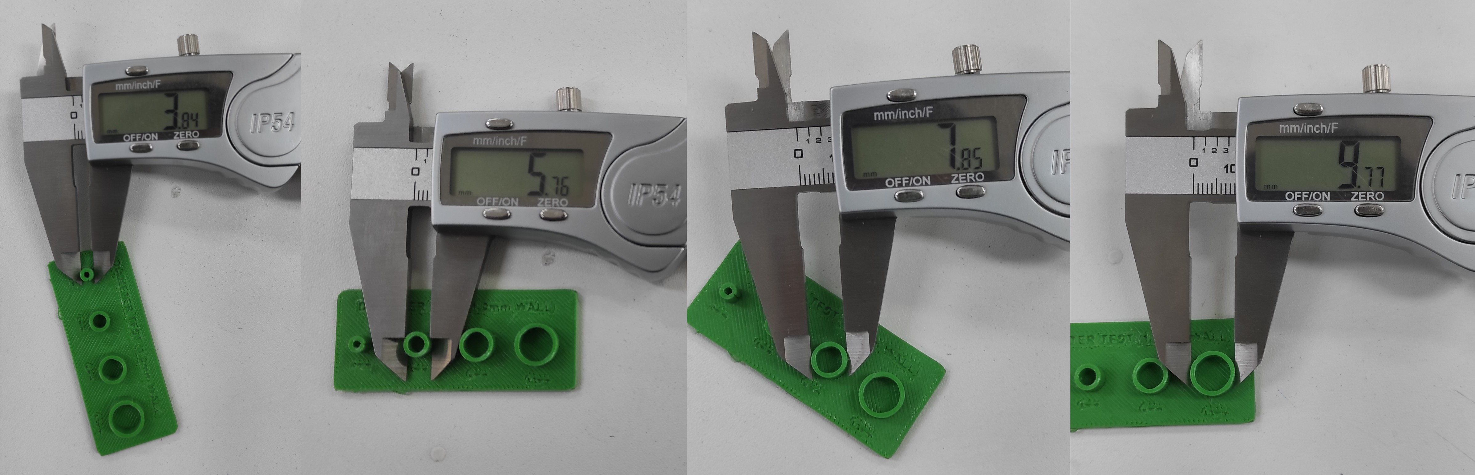
After printing the test, the results looked good. Now we need to take measurements to verify the dimensions.
Using a caliper, the dimensional variance was measured at 0.31 mm total. As this deviation is equally distributed on both sides, the required compensation per side is calculated to be 0.155 mm.
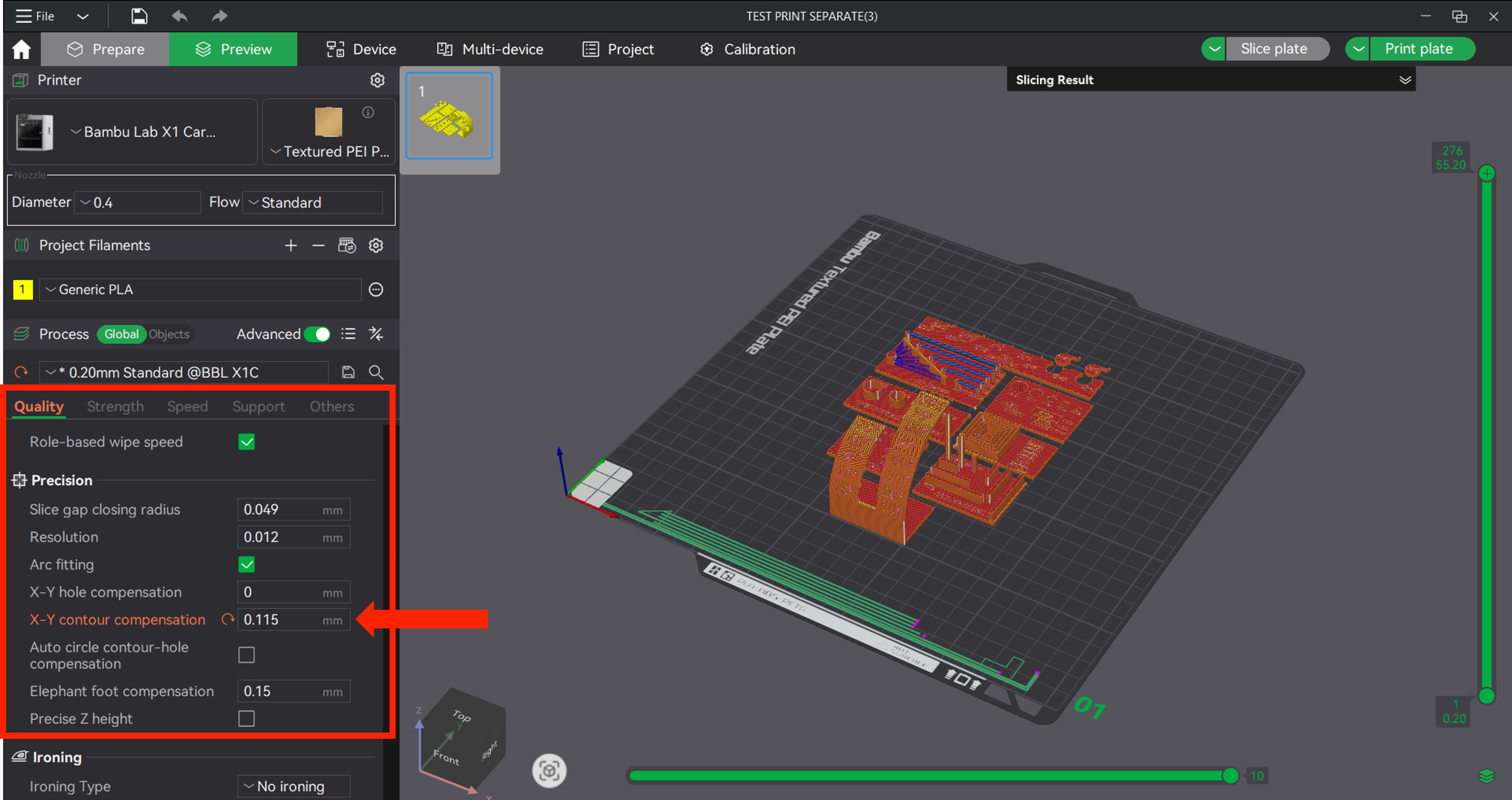
We'll apply the compensation in Bambu Studio using the XY contour compensation feature. Because our measured part came out smaller than intended, we need to input a positive value to expand the contour. Based on our calculation, we'll set it to +0.155 mm.
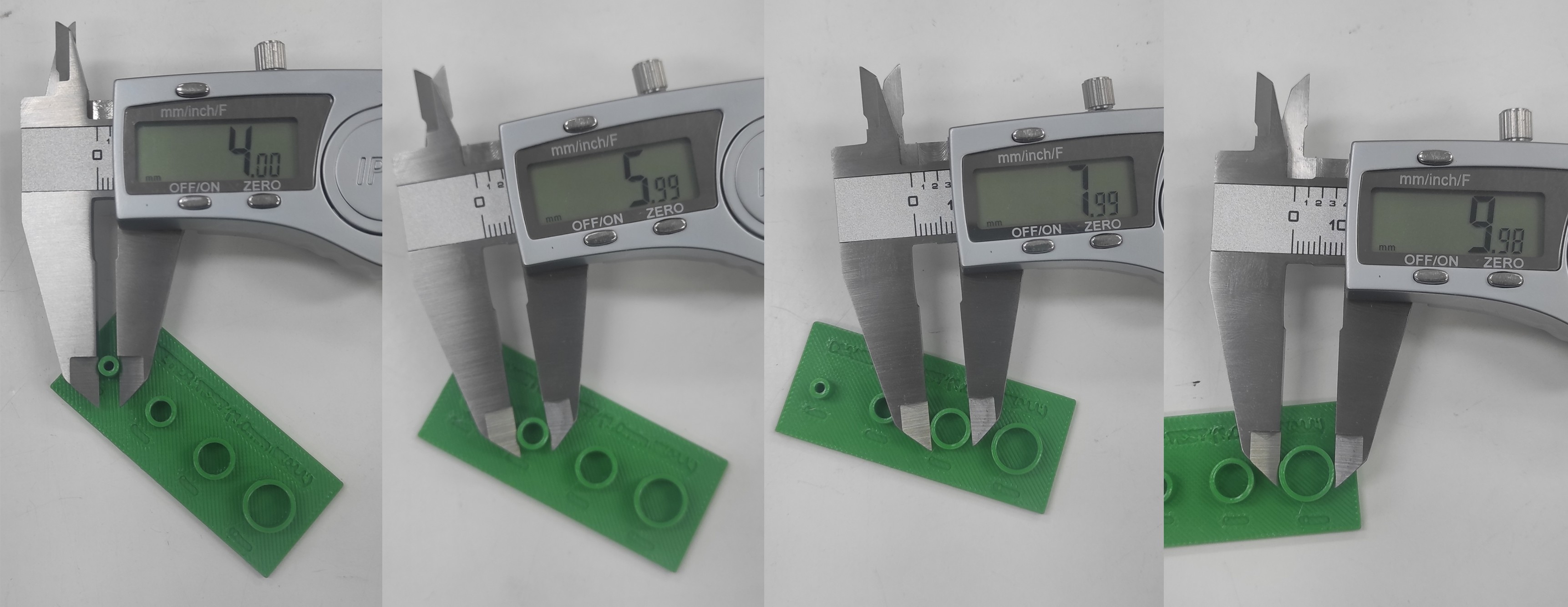
The second test print was successful. With the +0.155 mm XY contour compensation applied, the measured dimensions are now very close to the target, with a minimal deviation of just 0.01 mm.
Individual Assignment
6. 3d Design and Printing
6.1 Designing on Onshape
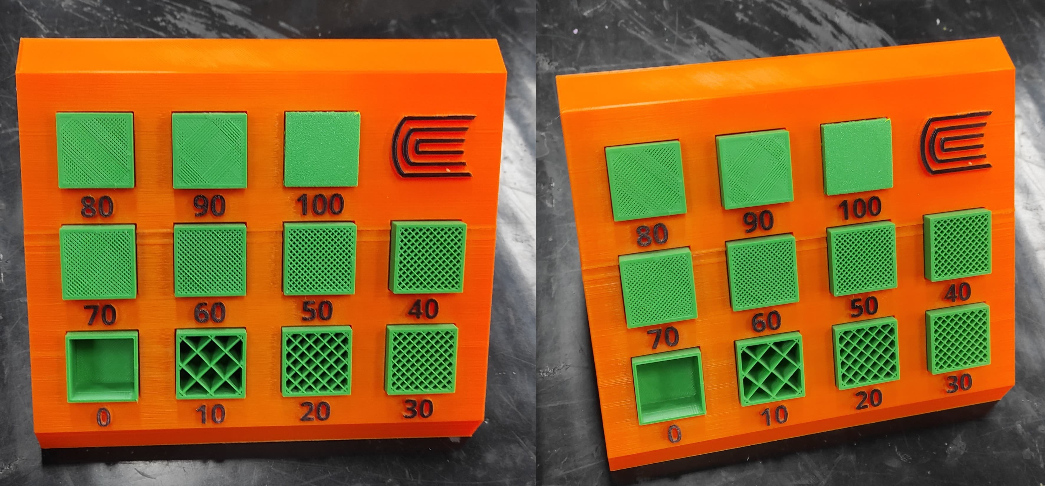
To illustrate the impact of infill in 3D printing, I created a test sample holder in Onshape. The design allows me to show infill variations from 0% all the way up to 100%.
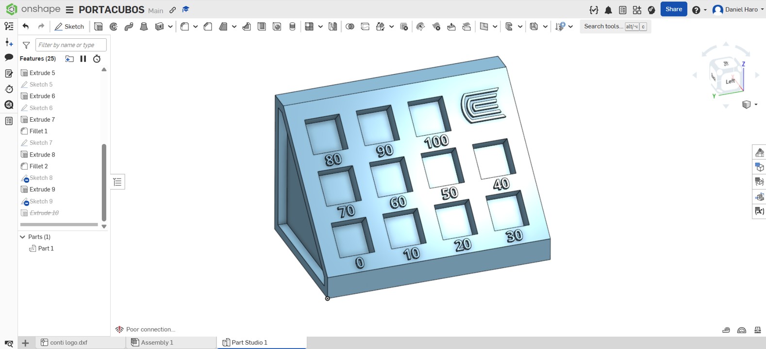
The print completed successfully, and the final result met my expectations. The infill samples, ranging from 0% to 100%, were properly positioned and clearly distinguishable.
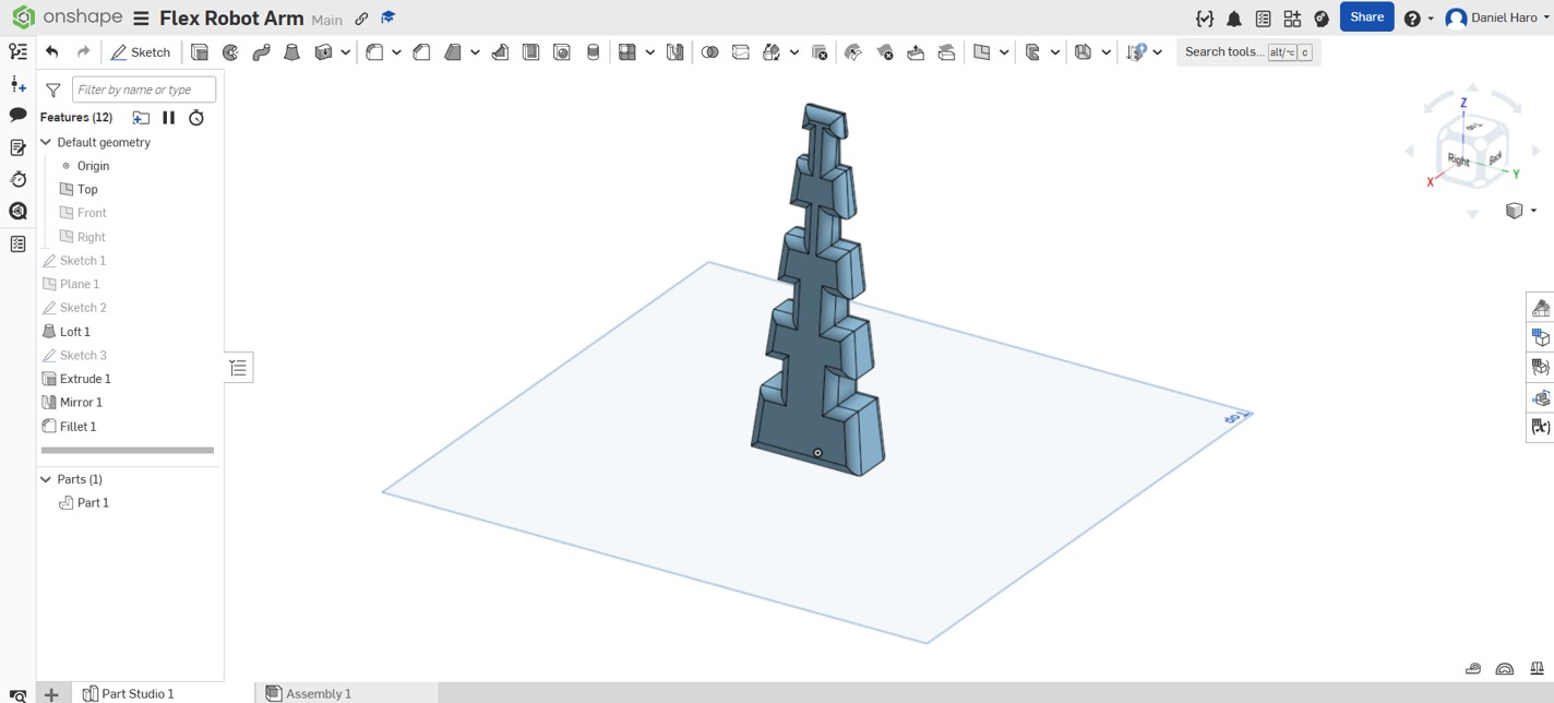
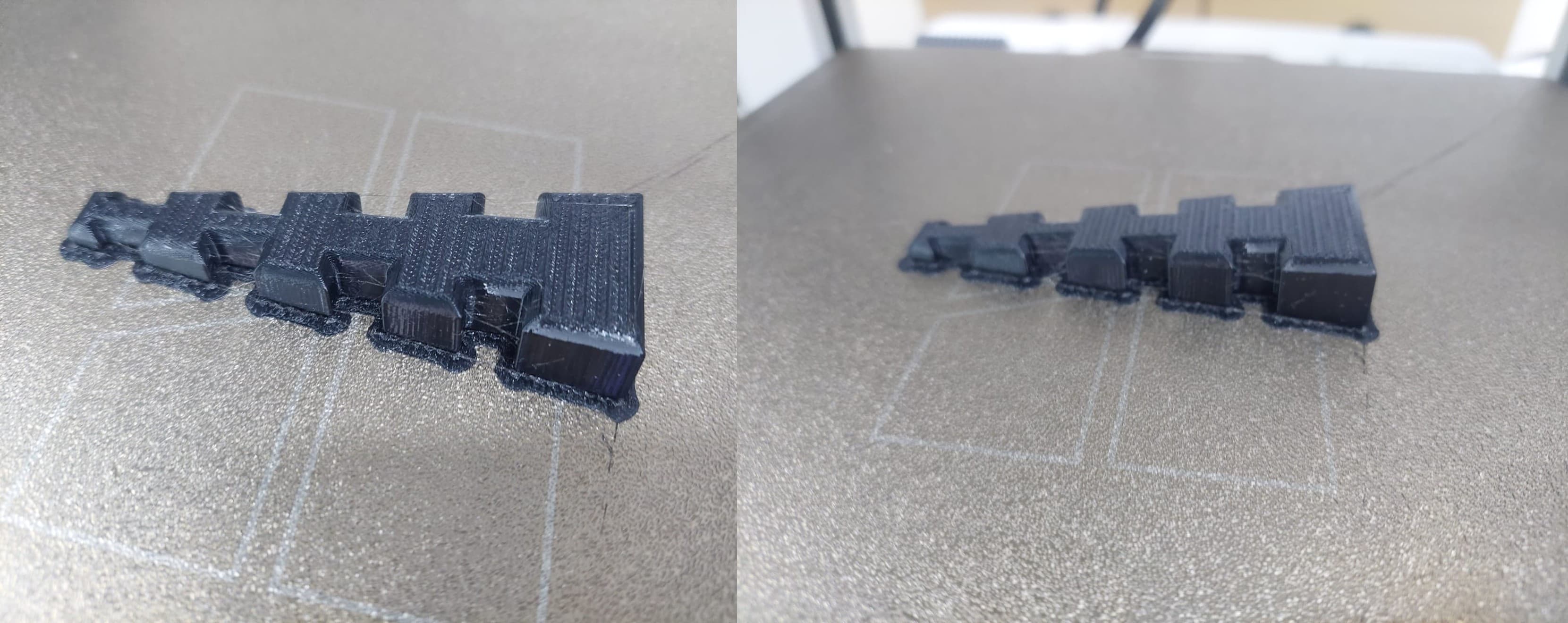
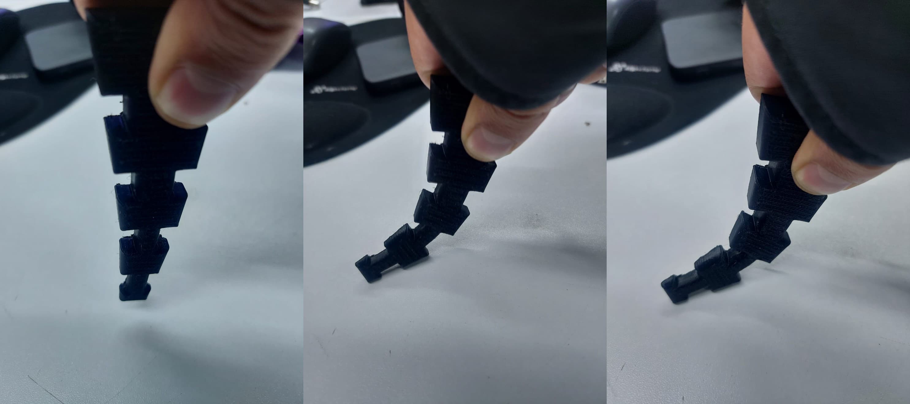
I decided to create a flexible robotic arm for future projects. I used Onshape to design it, and its flexible structure allows it to perform different movements.
The design was refined to improve object retention. Two additional articulations were introduced to optimize the holding function.
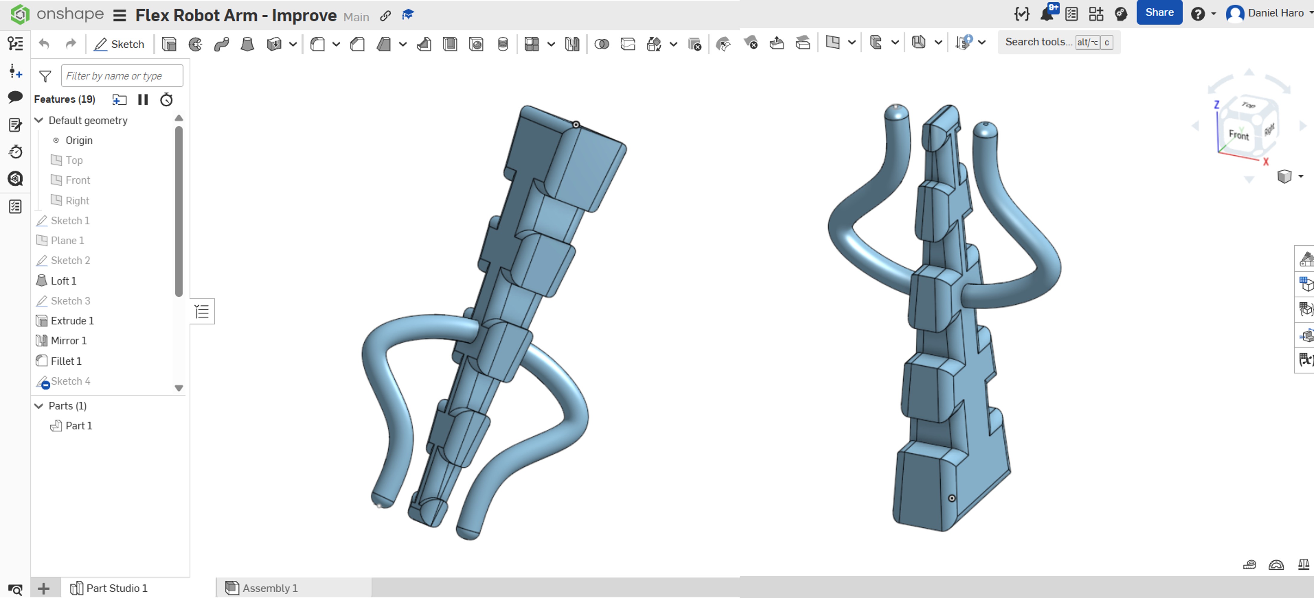
I 3D-printed the arm using TPU to allow flexion, since TPU is a flexible material. This flexibility enables the robotic arm to bend and adapt its shape, making it suitable for a wide range of movements and future applications. The use of TPU also helps absorb stress during motion, improving durability and performance.
Using 3D printing instead of other manufacturing technologies offers several advantages. First, it allows rapid prototyping, making it easy to design, test, and modify the robotic arm without high costs or long production times. Design changes can be implemented quickly by adjusting the digital model and reprinting the part. In addition, 3D printing enables the creation of complex and flexible geometries that are difficult or impossible to achieve with traditional manufacturing methods such as machining or molding. This is especially important for a flexible robotic arm, where internal structures and customized shapes are required to achieve controlled flexion. Another key advantage is material versatility. Flexible materials like TPU can be directly printed, eliminating the need for multiple components or assembly processes. This reduces weight, simplifies the design, and improves reliability. Finally, 3D printing is cost-effective for small production runs and educational or experimental projects, making it ideal for research, prototyping, and future development.
7. 3D Scanning
3D scanning is a technology that analyzes a real-world object or environment to collect data on its shape and, sometimes, its color (texture). The collected data is then used to create a 3D model—a digital representation of the physical object. You can think of it as the equivalent of a camera or a photocopier, but instead of capturing a flat 2D image, it captures the three-dimensional geometry of an object.
| ⚙️ GENERAL SPECIFICATIONS | |||
| Specification | Details | Specification | Details |
|---|---|---|---|
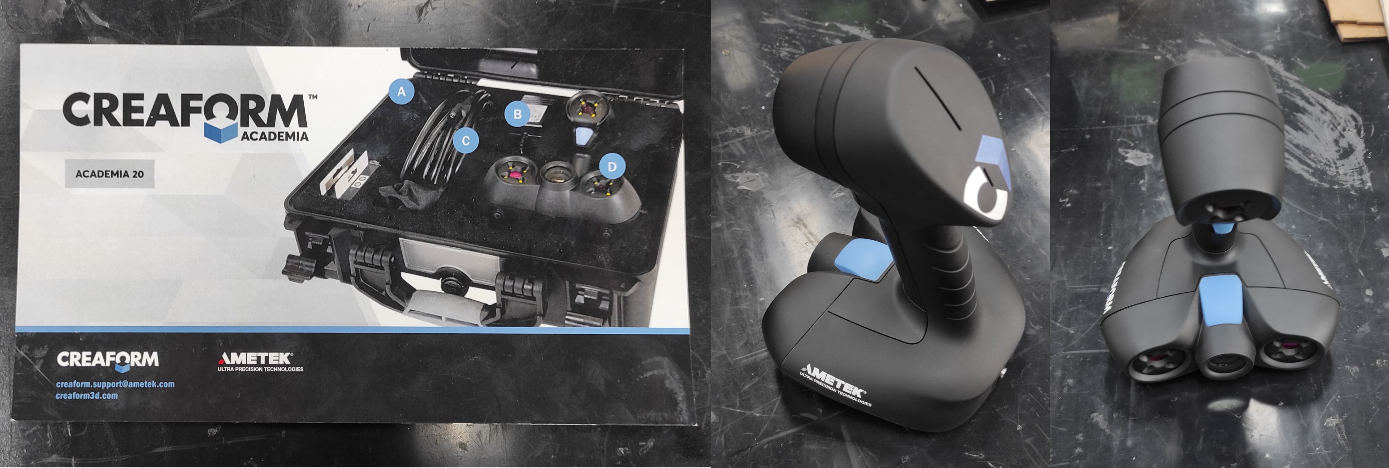
| Model | Go!SCAN 20 (CREAFORM) | Manufacturer | Creaform Inc. (AMETEK Ultra Precision Technologies) |
| Weight | 0.93 kg / 2.1 lbs | Dimensions | 154 × 178 × 235 mm (6.06 × 7.01 × 9.25 in.) |
| Technology | Structured light / White light (LED) | ||
| ────────────────── | |||
| 📊 PERFORMANCE SPECIFICATIONS | |||
| Specification | Value | Specification | Value |
| Measurement Rate | 550,000 measurements/second | Scan Area | 143 mm × 108 mm (5.6 in. × 4.3 in.) |
| Resolution | 0.100 mm (0.004 in.) | Accuracy | Up to 0.100 mm (0.004 in.) |
| Volumetric Accuracy | 0.300 mm/m (0.0036 in/ft) | Depth of Field | 100 mm (4 in.) |
| Stand-off Distance | 380 mm | ||
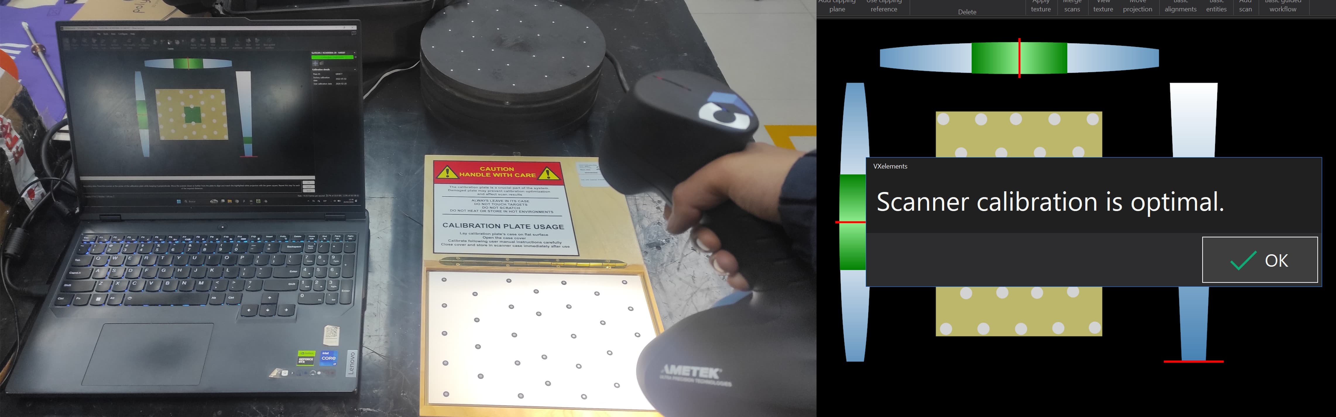
To ensure accurate scans, the Go!SCAN 20 must first be calibrated using the included calibration kit and reference panel.
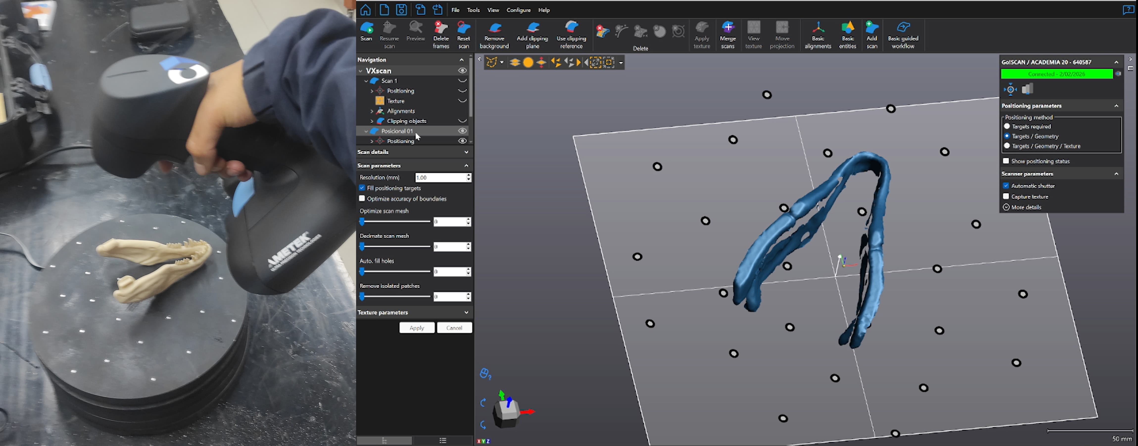
Once calibrated, I began scanning the part. The software displayed a live preview in real time, which made it easy to monitor the scan as I worked.
8. Learnings
Through this process of 3D scanning with the Go!SCAN 20 and integrating it with 3D printing, several important lessons were learned. First, calibration is a critical step that must be performed before each scanning session using the included kit, as it directly impacts the accuracy of the captured data. The real-time preview feature in the VXelements software proved to be invaluable, allowing immediate feedback and the ability to correct missing areas during scanning.
Additionally, designing a test sample holder in Onshape with infill percentages ranging from 0% to 100% provided an effective visual demonstration of how infill affects print strength, weight, and material usage. This simple model became a useful teaching tool for understanding infill properties in 3D printing.
9. Files
Here are the files available for download.