Week 4 Progress Checklist
| Status | Task |
|---|---|
| ✓ | Linked to the group assignment page |
| ✓ | Browsed and documented some information from a microcontroller's datasheet |
| ✓ | Programmed a board to interact and communicate |
| ✓ | Described the programming process(es) you used |
| ✓ | Documented how you made something with the vinyl cutter |
| ✓ | Included your source code |
| ✓ | Included ‘hero shot(s)’ |
Embedded Programming
Group Assignment
Embedded Architectures
1. Computer Architectures
Computer architecture refers to the design and organization of a computer's core components—specifically how the processor (CPU) , memory, and input/output systems interact to execute programs. In embedded systems, the architecture determines how instructions and data flow within the microcontroller, directly impacting performance, power consumption, and efficiency.
Two fundamental architectural models have shaped modern computing:
Von Neumann Architecture (also called Princeton Architecture): Uses a single memory space and a single bus for both instructions (the program) and data (variables). This simplifies design but creates a "bottleneck" when the CPU tries to access both simultaneously.
Harvard Architecture: Uses physically separate memories and buses for instructions and data. This allows parallel access, increasing speed and performance—ideal for real-time embedded applications.
Most modern microcontrollers, including the ESP32 and STM32, implement a Modified Harvard Architecture, which combines the parallel access benefits of Harvard with the flexibility to execute code from RAM like Von Neumann.
Most modern microcontrollers, including the ESP32 and STM32, implement a Modified Harvard Architecture, which combines the parallel access benefits of Harvard with the flexibility to execute code from RAM like Von Neumann.
2. Comparison: Von Neumann vs. Harvard Architecture
| Feature | Von Neumann Architecture (Princeton) | Harvard Architecture |
|---|---|---|
| Basic concept | Single memory and single bus for instructions and data | Separate memories and buses for instructions and data |
| Memory access | Sequential: competes for the same bus (cannot read instruction and data simultaneously) | Parallel: can read instruction and data at the same time |
| Main advantage | Simplicity and flexibility: easier to design and program; data can be treated as instructions (self-modifying code possible) | Higher speed and efficiency: parallel access means fewer instruction cycles for execution |
| Main disadvantage | "Von Neumann bottleneck": speed is limited by the transfer between memory and CPU | Greater complexity: requires more buses and memories, increasing chip cost and complexity |
| Flexibility | High: can execute code from RAM and modify it at runtime | Low: more rigid, designed for specific applications |
| Security | Lower: shared bus makes it more vulnerable to certain attacks | Higher: physical separation makes certain attacks more difficult |
| Typical use | General-purpose computers (PCs, servers) | Embedded systems, microcontrollers, DSPs (Digital Signal Processors) |
3. What Architecture Do ESP32 and STM32 Use?
Here's the interesting part for your assignment: most modern microcontrollers use a Hybrid or Modified Harvard architecture .
STM32 (ARM Cortex-M)
Base architecture: Modified Harvard
Explanation: ARM Cortex-M cores (M3, M4, etc.) internally have separate buses for instructions and data (I-Code bus and D-Code bus), allowing simultaneous access and improved performance . However, they can execute code from RAM (something a pure Harvard architecture wouldn't allow), hence the "modified" designation .
ESP32 (Tensilica Xtensa)
Base architecture: Modified Harvard
Explanation: The ESP32 uses a modified Harvard architecture with separate instruction and data buses. It allows simultaneous access to both instruction and data memory, improving performance. However, it also supports executing code from RAM, which is not typical of a pure Harvard architecture.
4. Application to Your Group Assignment
| Aspect | ESP32 | STM32 |
|---|---|---|
| Memory architecture | Modified Harvard | Modified Harvard |
| Core | Xtensa LX6 (configurable RISC) | ARM Cortex-M (standard RISC) |
| Practical benefit | Allows executing instructions while accessing Wi-Fi/Bluetooth data—crucial for real-time network applications | Enables high efficiency in control and signal processing with fast peripheral access |
| Real-world example | 📡 While transmitting a Wi-Fi packet (data), it can be processing the next protocol instruction | 🔧 While reading an ADC sensor (data), it can be calculating the next control instruction |
Understanding the difference between Von Neumann and Harvard architectures helped me grasp why today's microcontrollers can be so efficient. Although both STM32 and ESP32 use modified Harvard architectures, they do so with different philosophies: the STM32 optimizes peripheral access and control, while the ESP32 leverages parallelism to handle wireless communications without sacrificing performance. The 'Von Neumann bottleneck' remains relevant today, and these modern architectures are precisely an evolved solution to that historical problem.
Individual Assignment
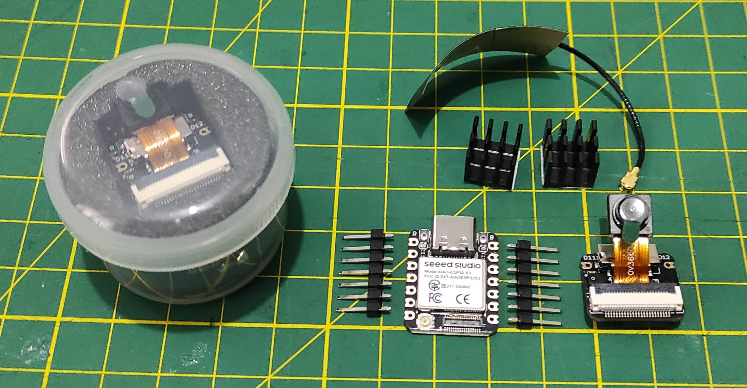
2. Exploring the XIAO ESP32S3 Sense:
2.1 XIAO ESP32S3 Sense
Seeed Studio XIAO ESP32S3 Sense integrates camera sensor, digital microphone and SD card supporting. Combining embedded ML computing power and photography capability, this development board can be your great tool to get started with intelligent voice and vision AI.
Product Link: Seeed Studio XIAO ESP32S3 Series
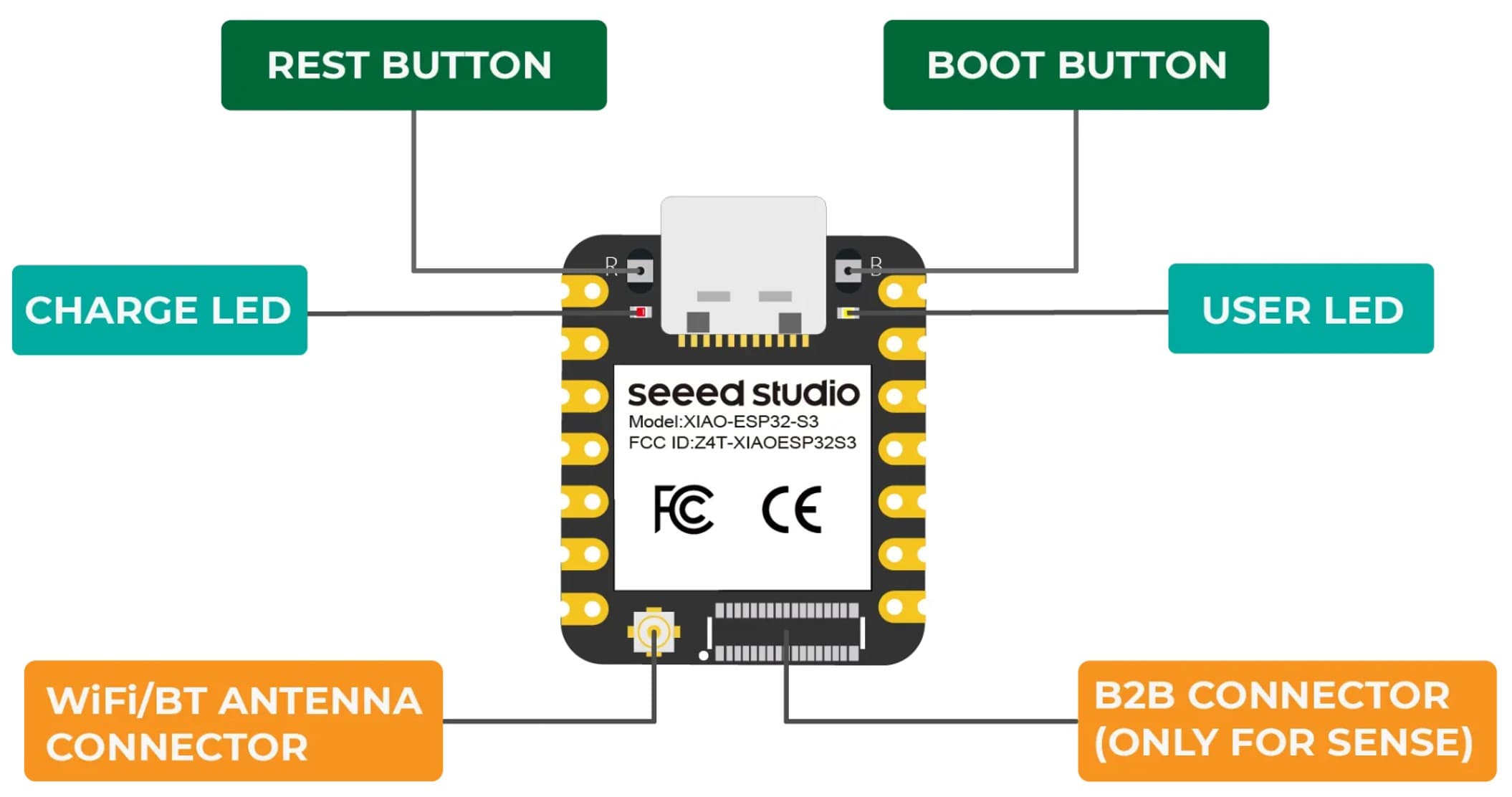
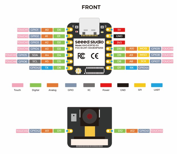
2.2 Pinout XIAO ESP32S3 Sense
The XIAO ESP32S3 Sense packs impressive I/O capabilities into its tiny 21 x 17.5mm form factor. Several pins serve dual purposes.
Seeed Studio XIAO ESP32S3 Sense integrates camera sensor, digital microphone and SD card supporting. Combining embedded ML computing power and photography capability, this development board can be your great tool to get started with intelligent voice and vision AI.
2.3 Pinout XIAO ESP32S3 Sense
| XIAO Pin | Function | Chip Pin | Alternate Functions | Description |
|---|---|---|---|---|
| 5V | VBUS | — | — | Power Input/Output (5V from USB, or input with diode) |
| GND | — | — | — | Ground |
| 3V3 | 3V3_OUT | — | — | Power Output (3.3V regulated, up to 700mA) |
| D0 | Analog | GPIO1 | TOUCH1 | GPIO, ADC |
| D1 | Analog | GPIO2 | TOUCH2 | GPIO, ADC |
| D2 | Analog | GPIO3 | TOUCH3 | GPIO, ADC (Strapping pin – JTAG source) |
| D3 | Analog | GPIO4 | TOUCH4 | GPIO, ADC |
| D4 | Analog,SDA | GPIO5 | TOUCH5 | GPIO, I2C Data, ADC |
| D5 | Analog,SCL | GPIO6 | TOUCH6 | GPIO, I2C Clock, ADC |
| D6 | TX | GPIO43 | — | GPIO, UART Transmit |
| D7 | RX | GPIO44 | — | GPIO, UART Receive |
| D8 | Analog,SCK | GPIO7 | TOUCH7 | GPIO, SPI Clock, ADC |
| D9 | Analog,MISO | GPIO8 | TOUCH8 | GPIO, SPI Data (MISO), ADC |
| D10 | Analog,MOSI | GPIO10 | TOUCH9 | GPIO, SPI Data (MOSI), ADC |
| D11 | Analog | GPIO42 | TOUCH12, JTAG (MTMS) | GPIO, ADC * |
| D12 | Analog | GPIO41 | TOUCH13, JTAG (MTDI) | GPIO, ADC * |
| ⚠️ D11/A11 (GPIO42) and D12/A12 (GPIO41) do NOT support ADC despite the label — they are used for digital microphone (PDM) and JTAG. | ||||
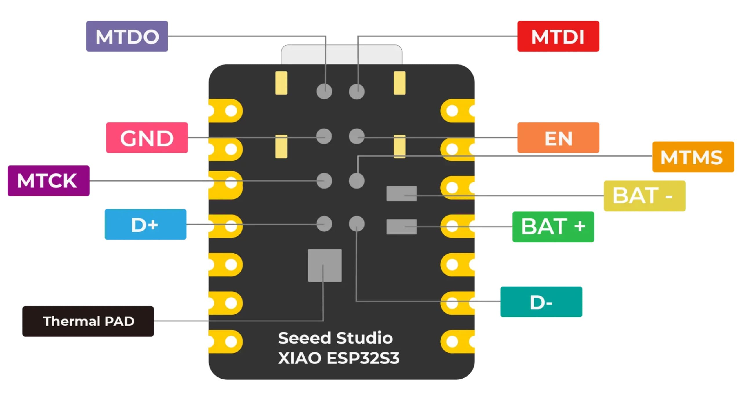
| MTDO | — | GPIO40 | JTAG | JTAG |
| MTDI | — | GPIO41 | JTAG, ADC | JTAG (also D12) |
| MTCK | — | GPIO39 | JTAG, ADC | JTAG |
| MTMS | — | GPIO42 | JTAG, ADC | JTAG (also D11) |
| Reset | EN | EN | — | Reset button / enable |
| Boot | — | GPIO0 | — | Enter Boot Mode (strapping) |
| U.FL-R-SMT1 | — | LNA_IN | — | U.FL antenna connector |
| CHARGE_LED | — | — | — | Charge indicator LED |
| USER_LED | — | GPIO21 | — | User programmable LED |
| Digital microphone_CLK | PDM CLK | GPIO42 | — | PDM clock for microphone (shares D11) |
| Digital microphone_DATA | PDM DATA | GPIO41 | — | PDM data for microphone (shares D12) |
| SD Card (CS) | SPI_CS | GPIO3 | — | SD card chip select (shares D2) |
| SD Card (SCK) | SPI_SCK | GPIO7 | — | SD card clock (shares D8) |
| SD Card (MISO) | SPI_MISO | GPIO8 | — | SD card data input (shares D9) |
| SD Card (MOSI) | SPI_MOSI | GPIO10 | — | SD card data output (shares D10) |
2.4 Programming XIAO ESP32S3 Sense
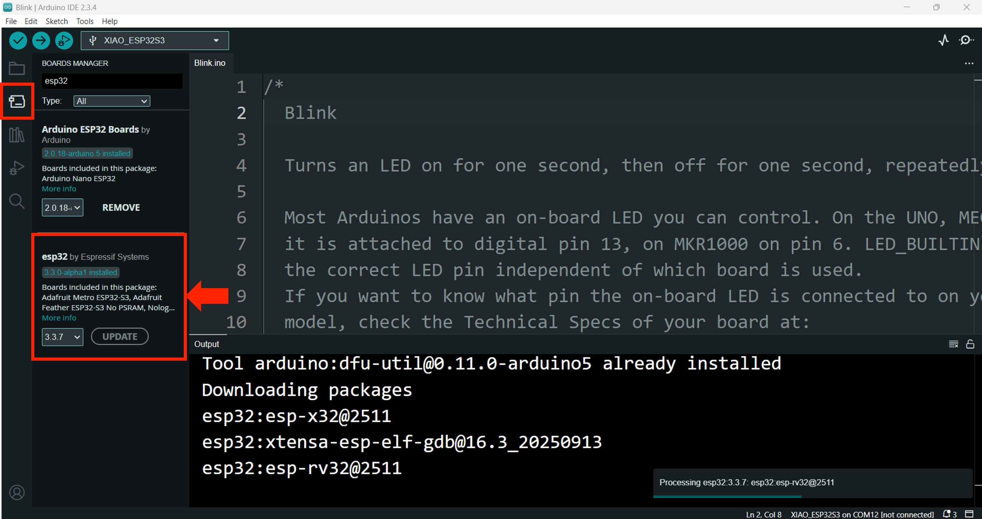
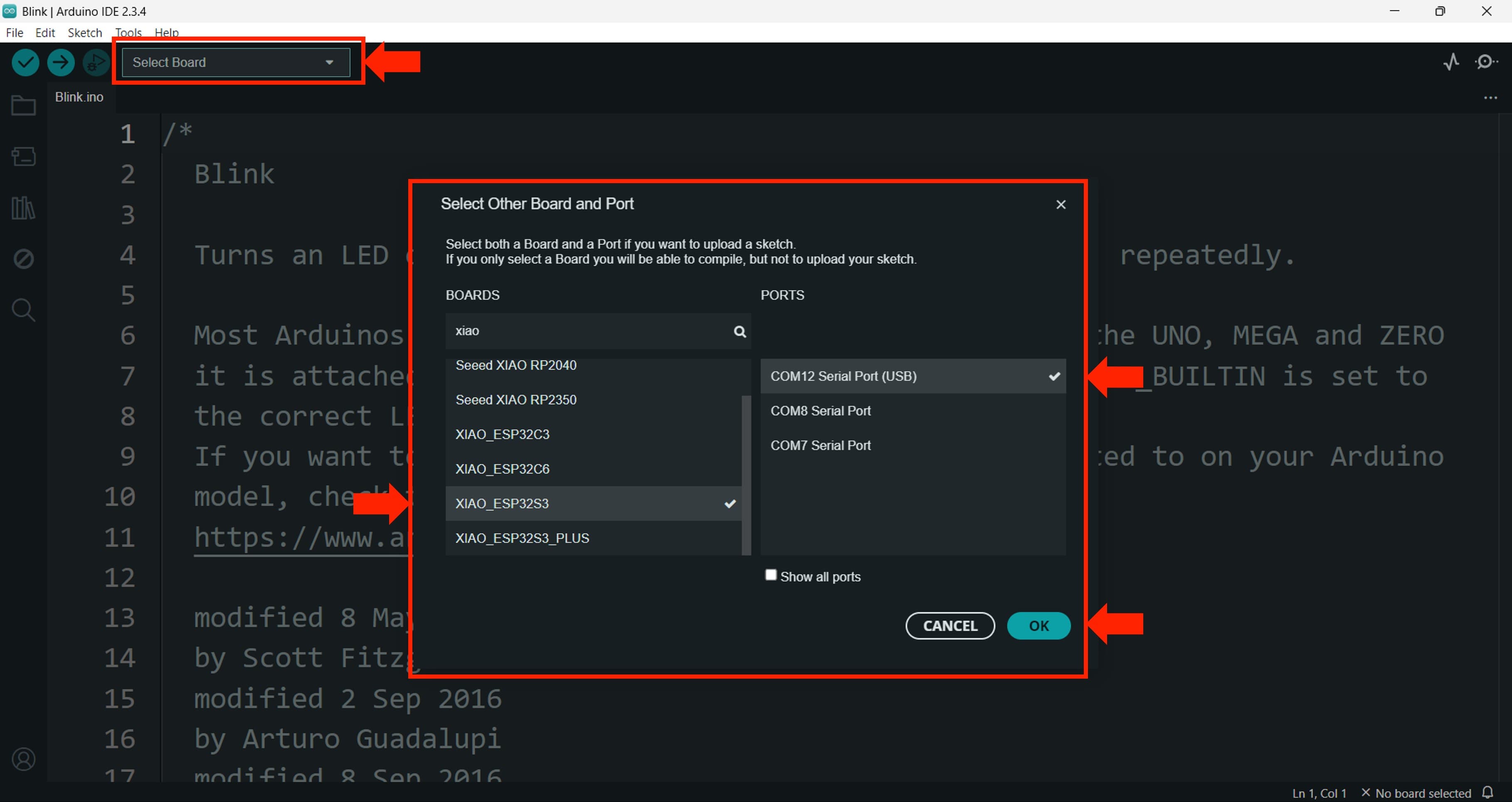
For programming I am going to use the Arduino IDE, which is a popular and user-friendly development environment for ESP32-based boards. I installed the necessary board support package for the ESP32S3 in the Arduino IDE and selected the appropriate board and port settings.
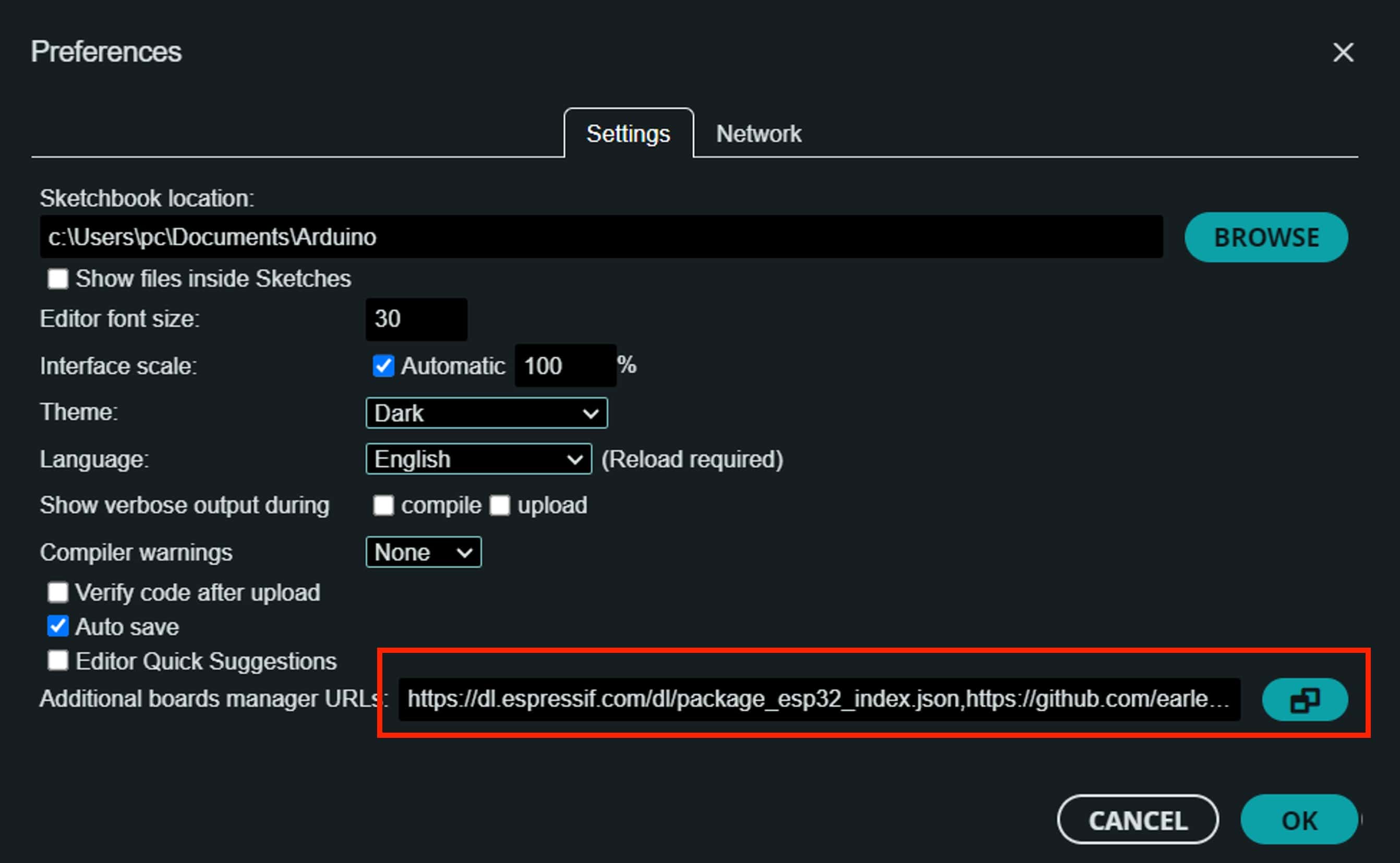
First, I need to add the libraries to the Arduino IDE. We need to copy in the addtional Boars,
Navigate to File > Preferences, and fill "Additional Boards Manager URLs" with the url below:https://raw.githubusercontent.com/espressif/arduino-esp32/gh-pages/package_esp32_index.json
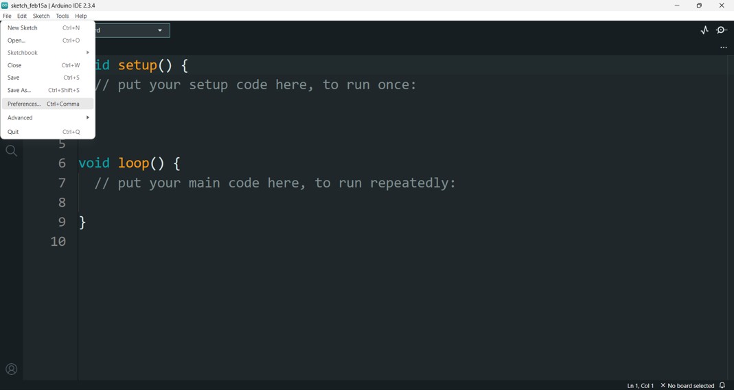
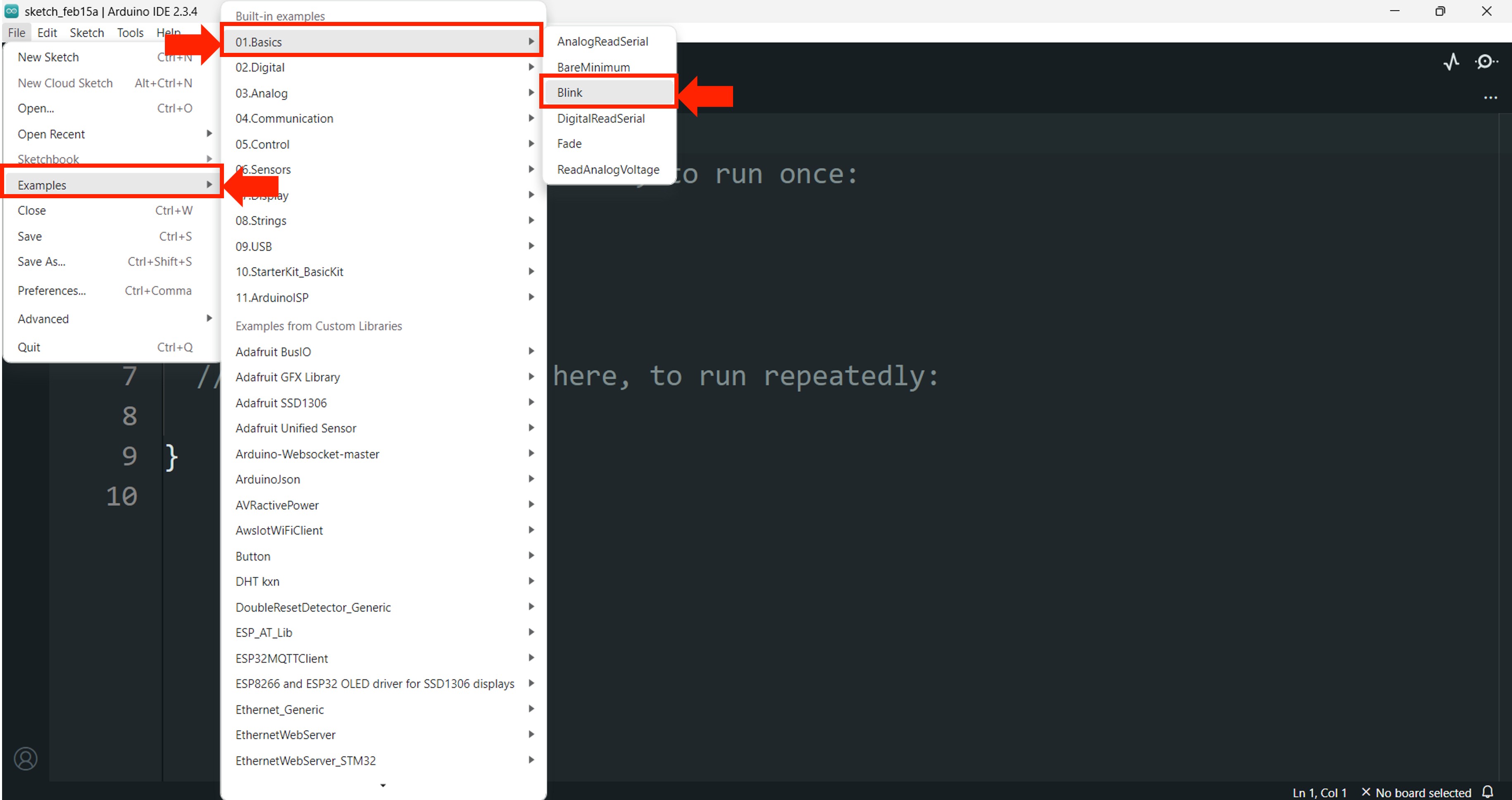
I'll start with the classic Blink example, which comes built into the Arduino IDE.
    void setup() {
    pinMode(LED_BUILTIN, OUTPUT);
    }

    void loop() {
    digitalWrite(LED_BUILTIN, HIGH);
    delay(200);
    digitalWrite(LED_BUILTIN, LOW);
    delay(200);
    }
2.5 Digital I/O - XIAO ESP32S3 Sense
Next, I wanted to test the digital input and output capabilities of the XIAO ESP32S3 Sense. I connected a push button to 3 of the GPIO pins and 3 LEDs to another GPIO pins. The code reads the state of the button and turns the LED on or off accordingly.
const int LED1 = D4;
const int LED2 = D3;
const int LED3 = D2;

const int BUTTON1 = D8;
const int BUTTON2 = D9;
const int BUTTON3 = D10;

void setup() {
  // Configurar LEDs como salidas
  pinMode(LED1, OUTPUT);
  pinMode(LED2, OUTPUT);
  pinMode(LED3, OUTPUT);

  pinMode(BUTTON1, INPUT);
  pinMode(BUTTON2, INPUT);
  pinMode(BUTTON3, INPUT);

  digitalWrite(LED1, LOW);
  digitalWrite(LED2, LOW);
  digitalWrite(LED3, LOW);

}

void loop() {

  if (digitalRead(BUTTON1) == HIGH) {
    digitalWrite(LED1, HIGH);
  } else {
    digitalWrite(LED1, LOW);
  }

  if (digitalRead(BUTTON2) == HIGH) {
    digitalWrite(LED2, HIGH);
  } else {
    digitalWrite(LED2, LOW);
  }

  if (digitalRead(BUTTON3) == HIGH) {
    digitalWrite(LED3, HIGH);
  } else {
    digitalWrite(LED3, LOW);
  }

  delay(50);
}
2.6 Analog I/O - XIAO ESP32S3 Sense
/**
 * Control RGB LED con potenciómetros
 * Conexiones:
 * - Potenciómetro Rojo: D0  → LED Rojo: D10 (con resistencia 330Ω)
 * - Potenciómetro Verde: D1 → LED Verde: D9 (con resistencia 330Ω)
 * - Potenciómetro Azul: D2  → LED Azul: D8 (con resistencia 330Ω)
 */

// Constantes para los pines
const int PIN_POT_R = D0;    // Potenciómetro Rojo (entrada ADC)
const int PIN_POT_G = D1;    // Potenciómetro Verde (entrada ADC)
const int PIN_POT_B = D2;    // Potenciómetro Azul (entrada ADC)

const int PIN_LED_R = D10;   // LED Rojo (salida PWM)
const int PIN_LED_G = D9;    // LED Verde (salida PWM)
const int PIN_LED_B = D8;    // LED Azul (salida PWM)

// Constantes para rangos
const int ADC_MAX = 4095;     // ESP32: ADC de 12 bits (0-4095)
const int PWM_MAX = 255;      // PWM de 8 bits (0-255)

void setup() {
  // Configurar pines de potenciómetros como entradas
  pinMode(PIN_POT_R, INPUT);
  pinMode(PIN_POT_G, INPUT);
  pinMode(PIN_POT_B, INPUT);

  // Configurar pines de LEDs como salidas
  pinMode(PIN_LED_R, OUTPUT);
  pinMode(PIN_LED_G, OUTPUT);
  pinMode(PIN_LED_B, OUTPUT);

  // Para mejor resolución, puedes usar PWM de 12 bits:
  // analogWriteResolution(12);
  // Y entonces PWM_MAX sería 4095
}

void loop() {
  // Leer potenciómetros (0-4095) y mapear a PWM (0-255) directamente
  analogWrite(PIN_LED_R, map(analogRead(PIN_POT_R), 0, ADC_MAX, 0, PWM_MAX));
  analogWrite(PIN_LED_G, map(analogRead(PIN_POT_G), 0, ADC_MAX, 0, PWM_MAX));
  analogWrite(PIN_LED_B, map(analogRead(PIN_POT_B), 0, ADC_MAX, 0, PWM_MAX));

  // Pequeña pausa para estabilidad
  delay(10);
}
2.7 WIRELESS CONTROL - XIAO ESP32S3 Sense
Finally, I wanted to test the wireless capabilities of the XIAO ESP32S3 Sense. I set up a simple web server on the board that allows me to control an LED from a web browser. The code creates a Wi-Fi access point and serves a webpage with buttons to turn the LED on and off.
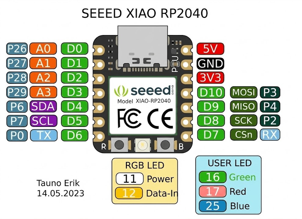
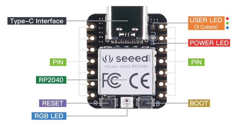
3. XIAO RP2040
The Seeed Studio XIAO RP2040 carries the powerful Dual-core RP2040 processor that can flexible clock running up to 133 MHz which is a low-power microcontrollers. On the Seeed Studio XIAO RP2040 there is also 264KB of SRAM, and 2MB of on-board Flash memory which can provide more program to save and run. On the other hand, this little board has good performance in processing but needs less power.
Caution
caution For general I/O pins: Working voltage of MCU is 3.3V. Voltage input connected to general I/O pins may cause chip damage if it's higher than 3.3V. For power supply pins: The built-in DC-DC converter circuit able to change 5V voltage into 3.3V allows to power the device with a 5V supply via VIN-PIN and 5V-PIN. XIAO RP2040 currently only supports battery power supply and cannot connect to Type-C while a battery is connected, as it may pose a safety risk.
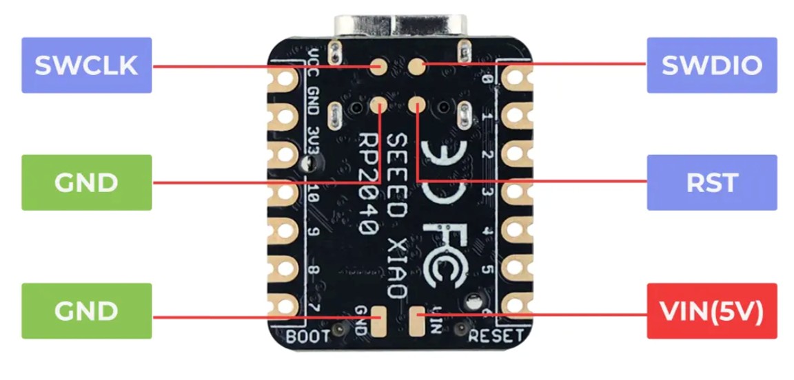
3.1 Pinout Xiao RP2040
The XIAO RP2040 squeezes the power of the Raspberry Pi RP2040 chip into the same tiny 20 x 17.5mm form factor as its counterparts . It provides a versatile set of I/O options for various projects.
| Feature | Details |
|---|---|
| Digital I/O Pins | 11 GPIO |
| Analog Inputs | 4 (12-bit capable) ADC |
| PWM Pins | 11 (all digital pins) PWM |
| I2C Interface | 1 SDA/SCL |
| UART | 1 TX/RX |
| SPI | 1 MISO/MOSI/SCK/SS |
| Power Pins |
3.3V, 5V (VIN), GND
🔌 3.3V
⚡ 5V (VIN)
⏚ GND
|
3.2 Programming the Xiao RP2040
To program the XIAO RP2040, I used the Arduino IDE, which provides a user-friendly interface for coding and uploading programs to the microcontroller. I installed the necessary board support package for the RP2040 and selected the appropriate board and port settings in the IDE.
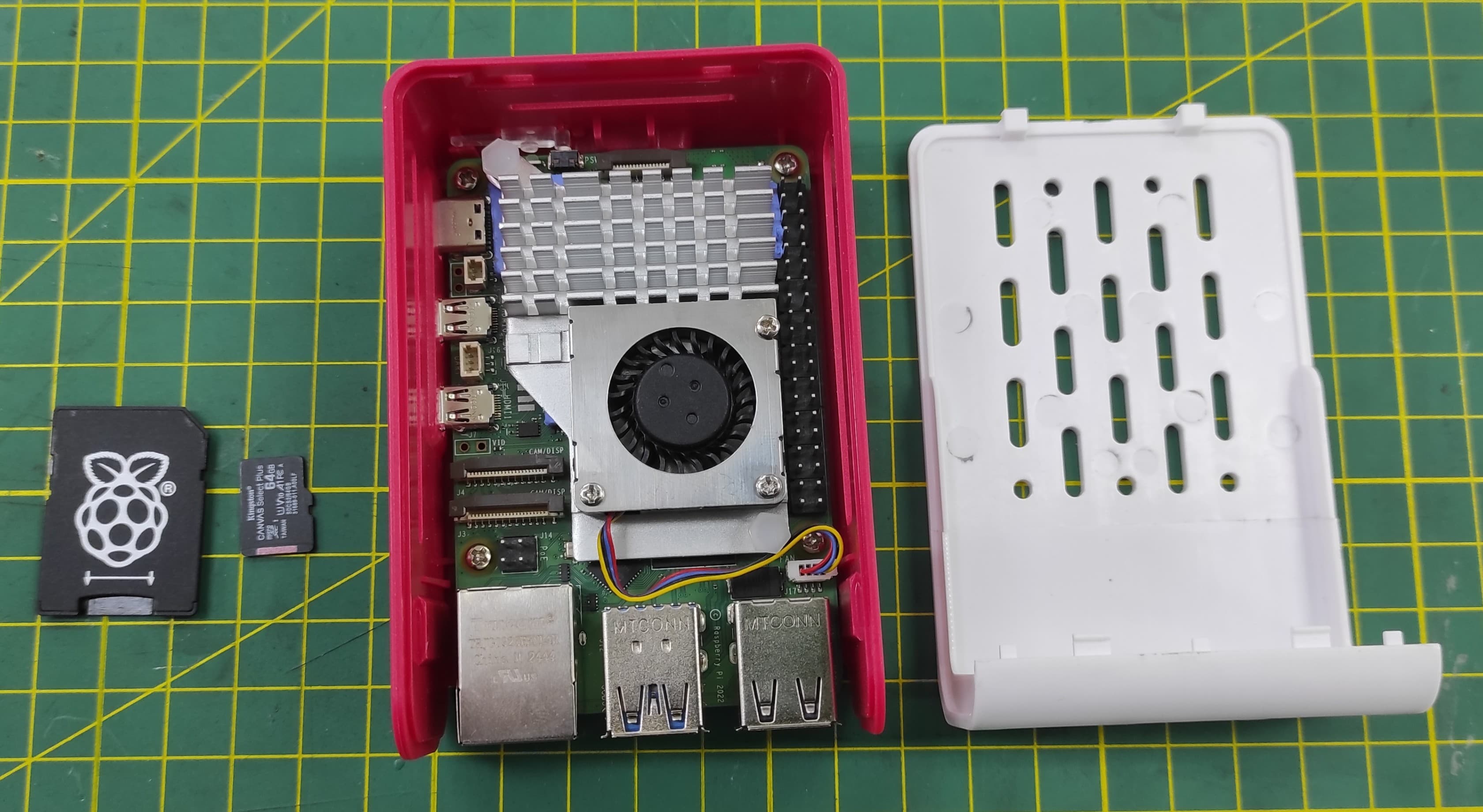
4. Raspberry Pi 5
The Raspberry Pi 5 is a powerful single-board computer that features a quad-core ARM Cortex-A76 processor running at 2.4 GHz, with 4GB, 8GB, or 16GB LPDDR4X RAM options, and support for dual 4K displays. It also includes built-in Wi-Fi 5 and Bluetooth 5.0 connectivity, making it ideal for a wide range of applications from home automation to robotics projects.
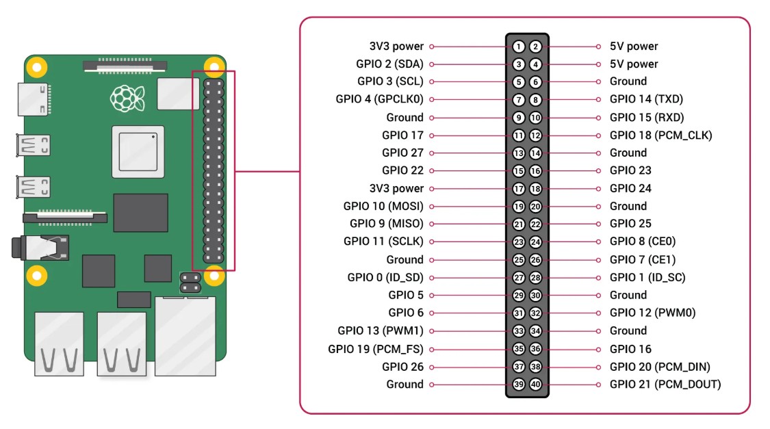
4.1 Pinout Raspberry Pi 5
The Raspberry Pi 5 retains the ubiquitous 40-pin GPIO header found on its predecessors, ensuring broad compatibility with HATs and existing projects . However, beneath the surface, significant changes have been made. A key architectural shift is the introduction of the RP1 I/O controller, a custom chip developed by Raspberry Pi that now manages the GPIO and various interfaces, leading to enhanced performance and functionality .
The header provides a mix of power, ground, and multi-functional general-purpose input/output pins, all operating at 3.3V logic . When working with the pins, two numbering schemes are commonly referenced: the physical pin numbers on the header (1-40) and the Broadcom (BCM) GPIO numbers used in programming . The pinout includes dedicated pins for popular communication protocols:
| Feature | Details |
|---|---|
| Digital I/O Pins | 28 multi-function GPIO pins |
| Power Pins | 2x 5V (pins 2, 4), 2x 3.3V (pins 1, 17) |
| Ground Pins | 8 (pins 6, 9, 14, 20, 25, 30, 34, 39) |
| I2C Interface | Available on pins 3 (SDA) and 5 (SCL), with additional I2C controllers available on other pins |
| UART | Primary UART on pins 8 (TX) and 10 (RX) |
| SPI | Main SPI bus on pins 19, 21, 23, 24, 26, with multiple additional SPI interfaces accessible via pin multiplexing |
| PWM | Hardware PWM available on multiple pins, including GPIO12, 13, 18, 19 |
4.2 Installing Operating System Raspberry Pi 5
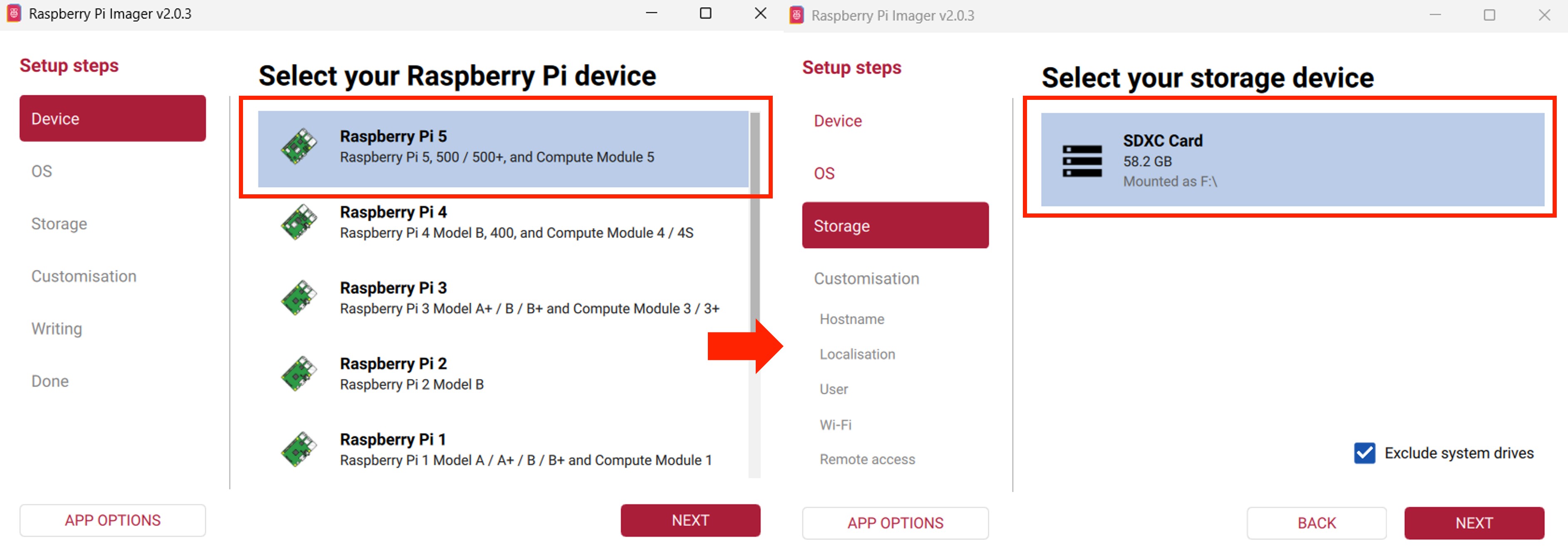
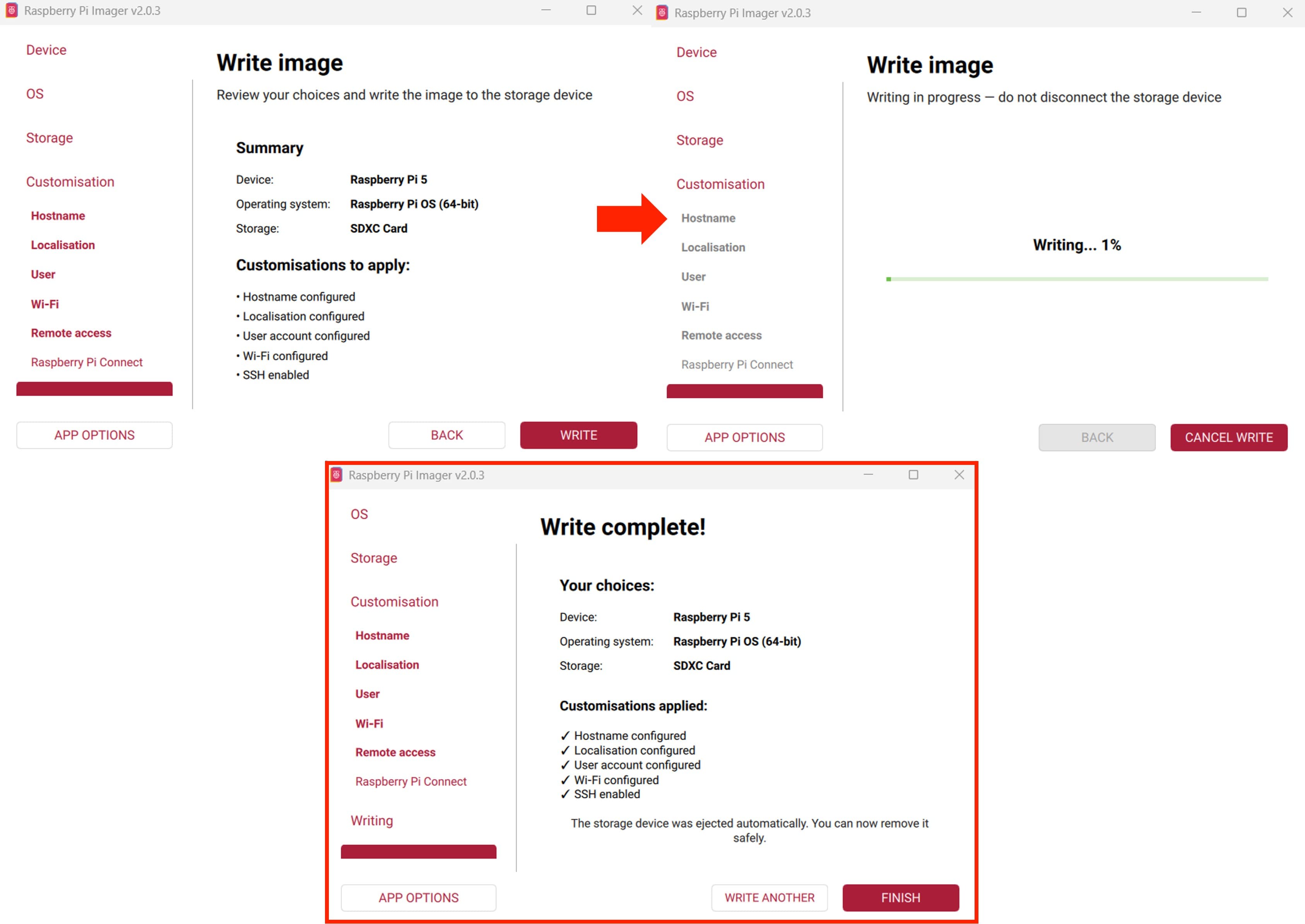
To get started, We need to flash the operating system onto a microSD card. The recommended method is using the official Raspberry Pi Imager tool, which automates the process of downloading and writing the OS image to the card . Simply install the Imager on your computer, select your Raspberry Pi model and desired OS, choose your microSD card, and write the image
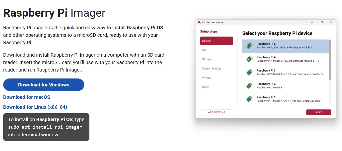
To install the operating system on your Raspberry Pi 5, follow the steps below.
5. Learning
During this week, I learned about the XIAO ESP32S3 Sense, the XIAO RP2040, and the Raspberry Pi 5. I explored their specifications, pinouts, and programming capabilities. I also gained hands-on experience with programming the XIAO ESP32S3 Sense using the Arduino IDE, testing its digital and analog I/O functionalities, and utilizing its wireless capabilities. Additionally, I learned how to install the operating system on the Raspberry Pi 5 and explored its pinout and features.
6. Files
Here are the files available for download.