Week 16 Progress Checklist
| Status | Task |
|---|---|
| ✓ | Made a plan for system integration for your final project? |
| ✓ | Documented your plan with CAD and/or sketches for system integration? |
| ✓ | Implemented methods of packaging? |
| ✓ | designed your final project to look like a finished product? |
| ✓ | Documented system integration of your final project? |
| ✓ | Linked to your system integration documentation from your final project page? |
System Integration
1. Plan for System Integration
In order to complete the system integration, I have created a detailed plan that outlines the steps and considerations for connecting the control and power blocks.
| Phase | Activity | Description | Expected Result |
|---|---|---|---|
| 1 | System Definition | Define the architecture and interaction between control and power blocks. | Clear integration strategy. |
| 2 | Interface Identification | Identify communication signals, power lines, and connectors. | Defined interfaces. |
| 3 | Module Testing | Test each subsystem independently before integration. | Validated standalone modules. |
| 4 | Hardware Integration | Connect the control board and power board. | Correct electrical integration. |
| 5 | Firmware Integration | Test firmware communication and synchronization. | Stable system communication. |
| 6 | Power Validation | Verify voltage and current stability. | Reliable power distribution. |
| 7 | Functional Testing | Run complete system tests. | Fully operational system. |
| 8 | Debugging & Optimization | Fix issues and improve performance. | Optimized and stable prototype. |
| 9 | Mechanical Integration | Assemble all modules into the final structure. | Compact final prototype. |
| 10 | Documentation | Document process, testing, and final results. | Complete Fab Academy presentation. |
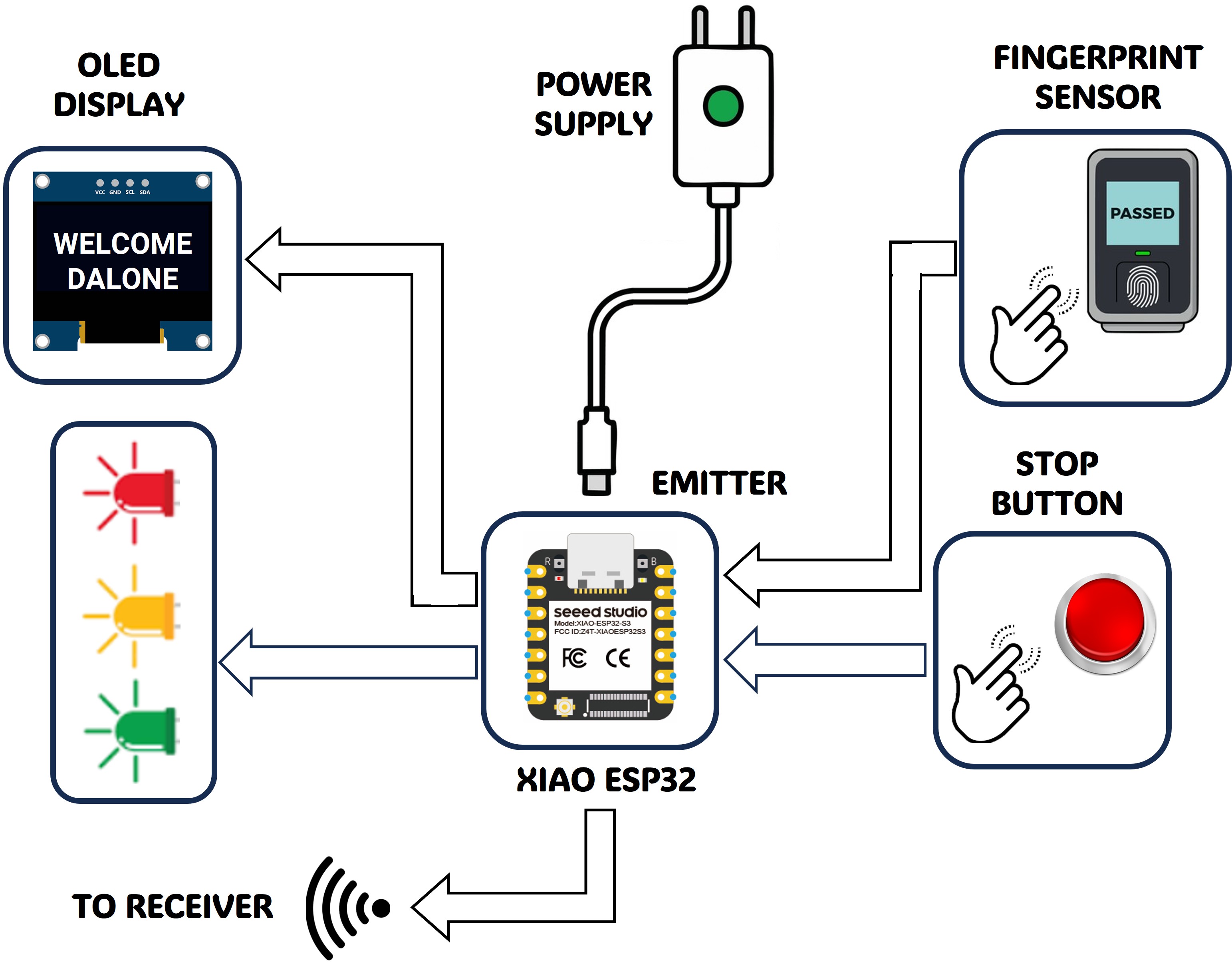
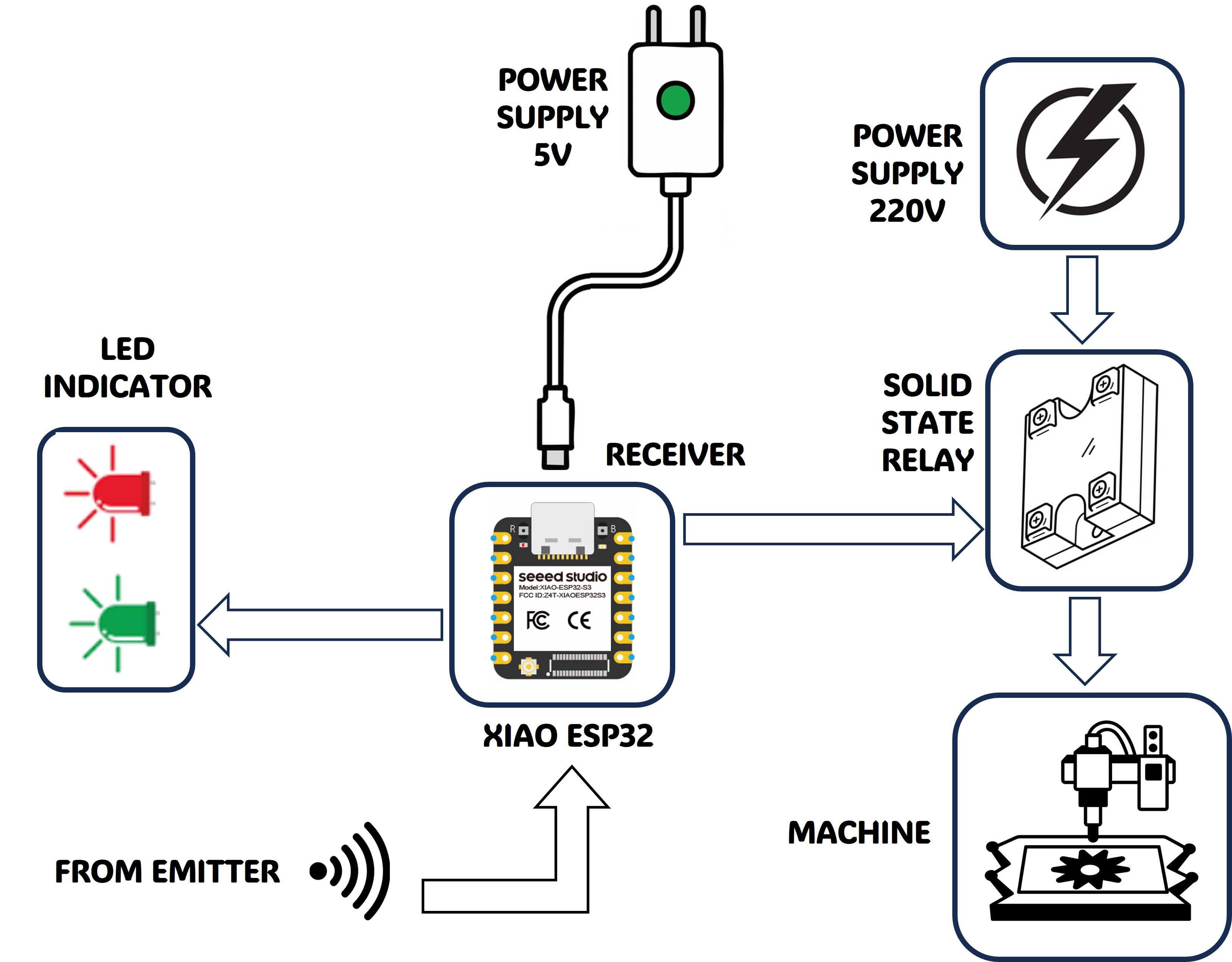
2. System definition and identification
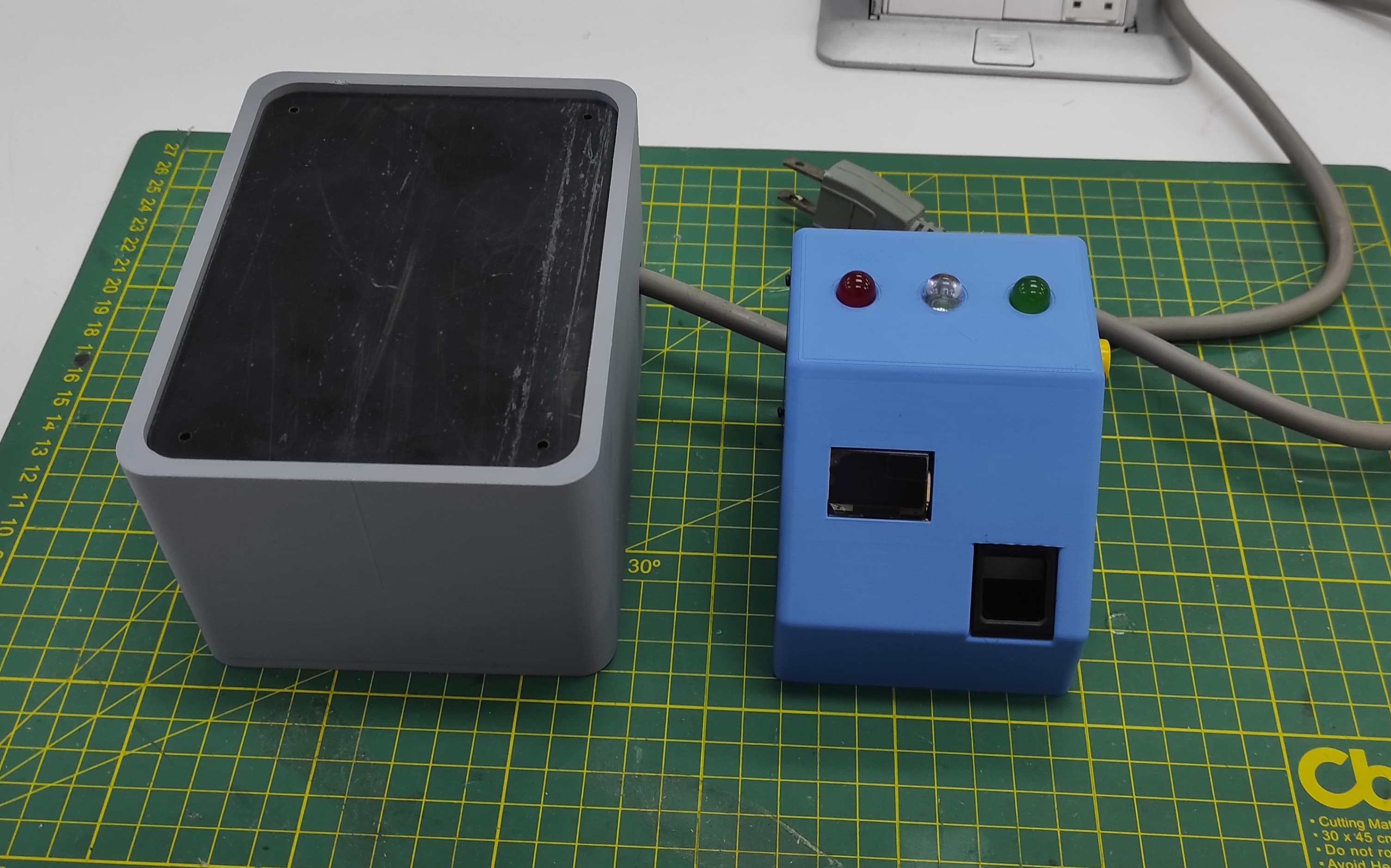
For this project, there are two blocks: the first is the control block, and the second is the power block. The images below show the integration between them.
3. Module Testing - Hardware Integration
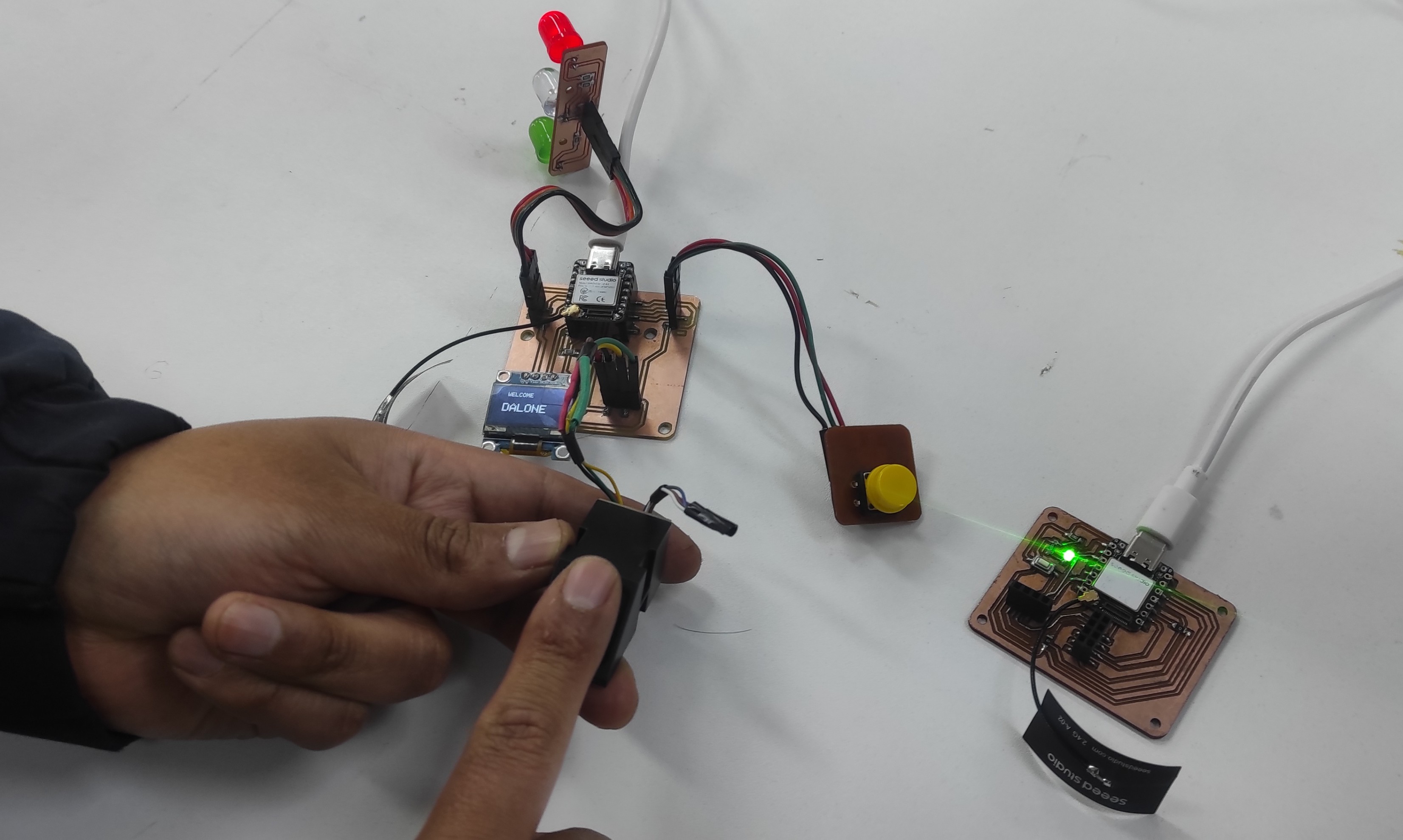
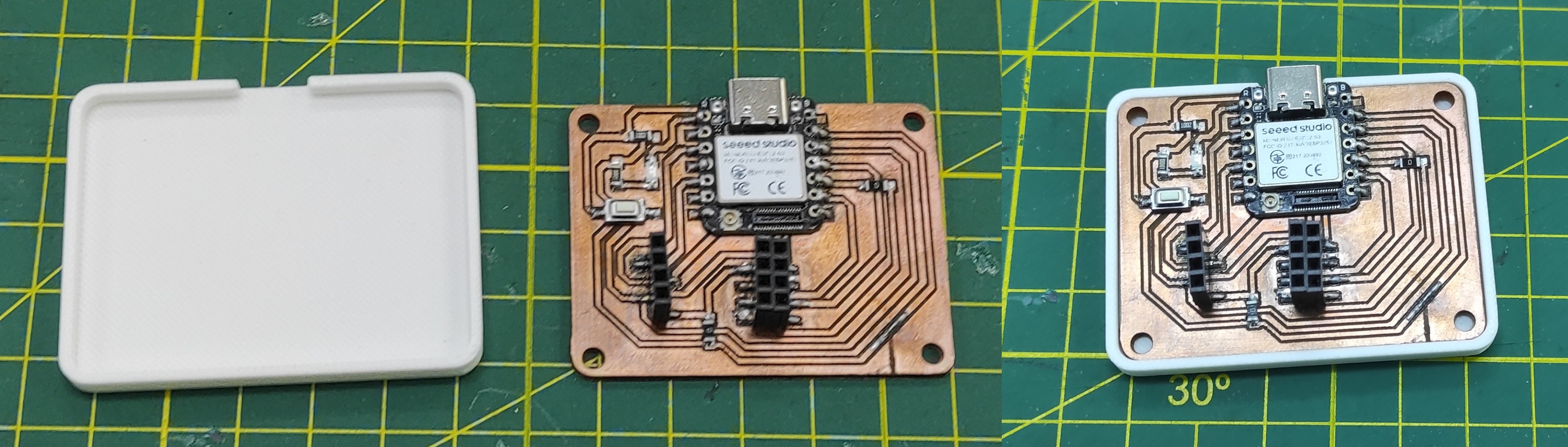
I tested the hardware integration between the control and power blocks to verify proper communication, connectivity, and overall system functionality.
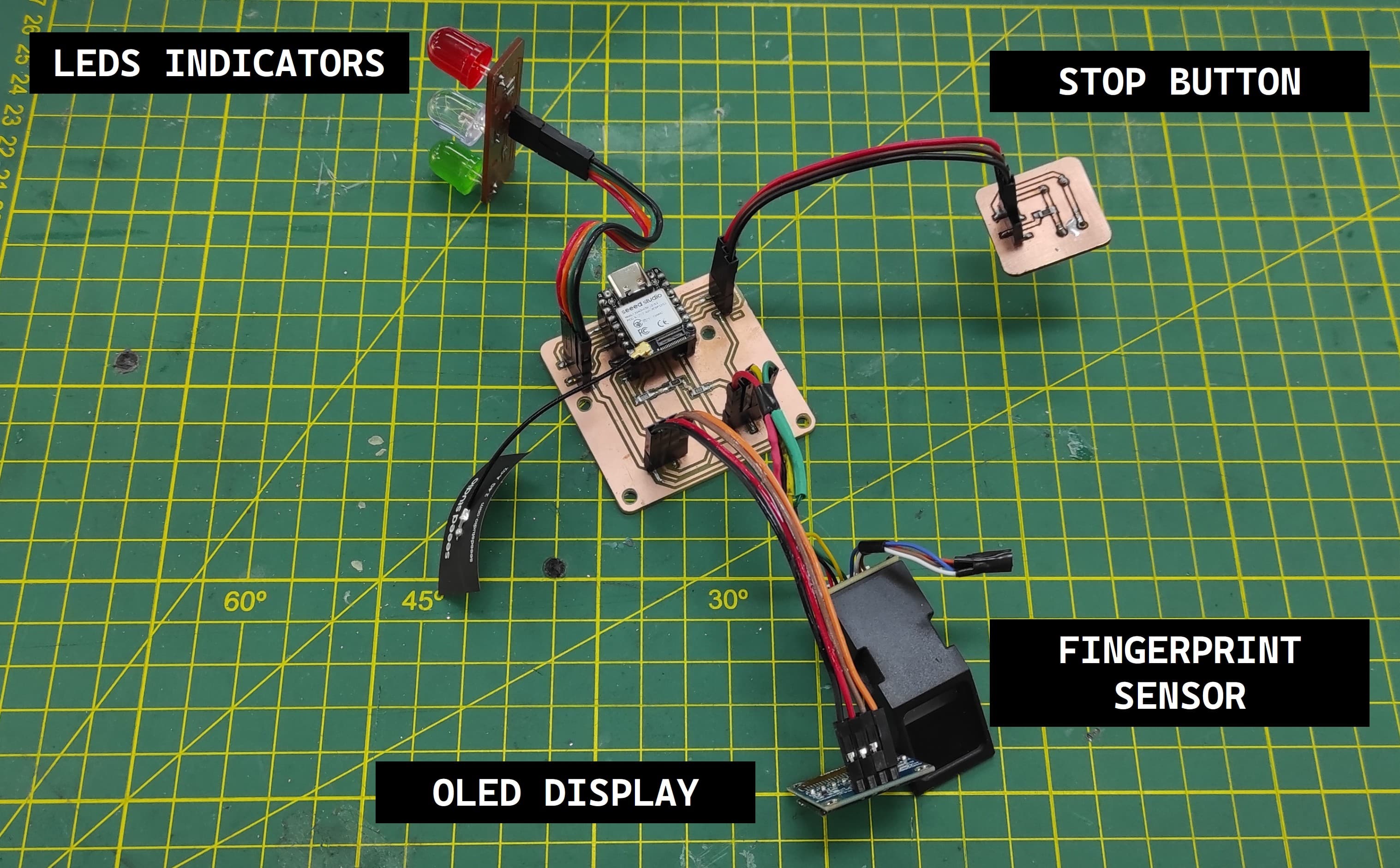
I performed a quick test on all the devices to verify that each one was correctly recognized and functioning properly.
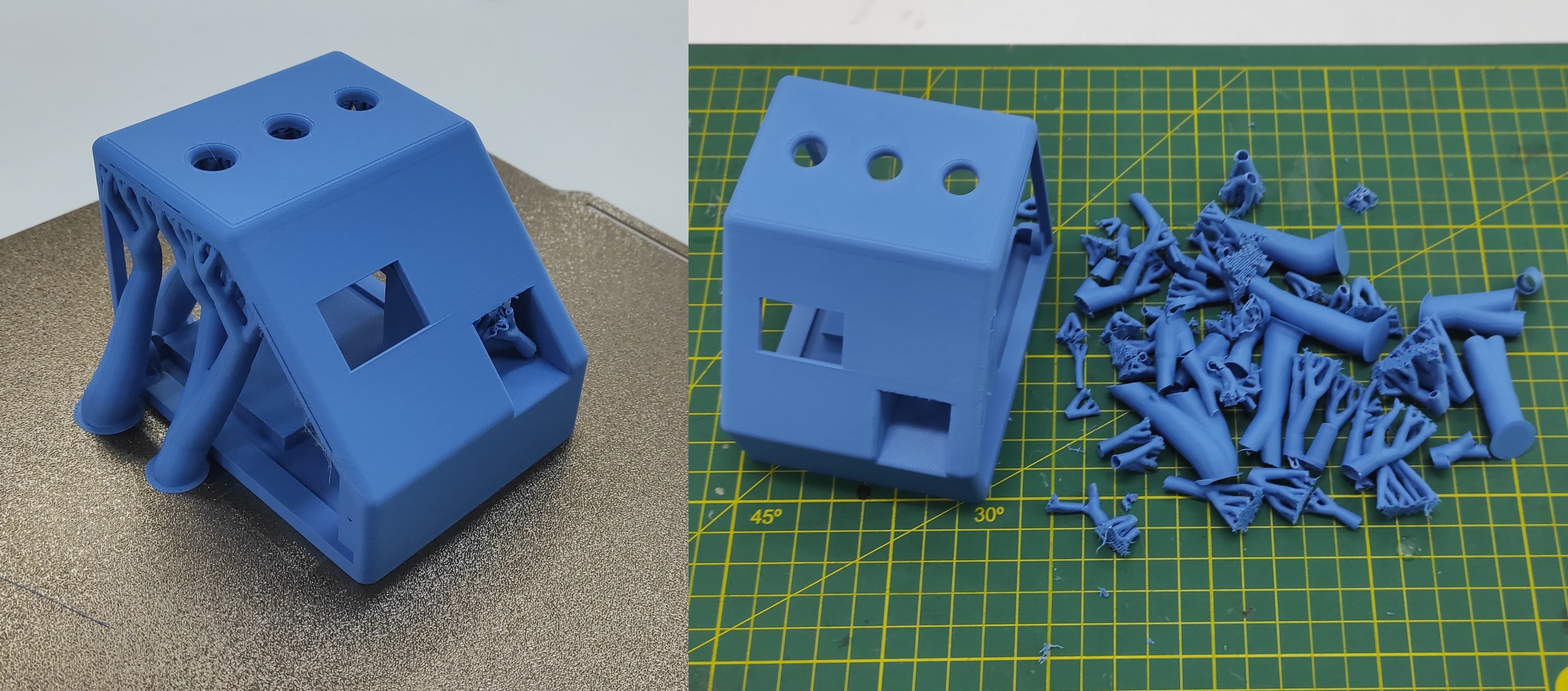
4. Mechanical Integration
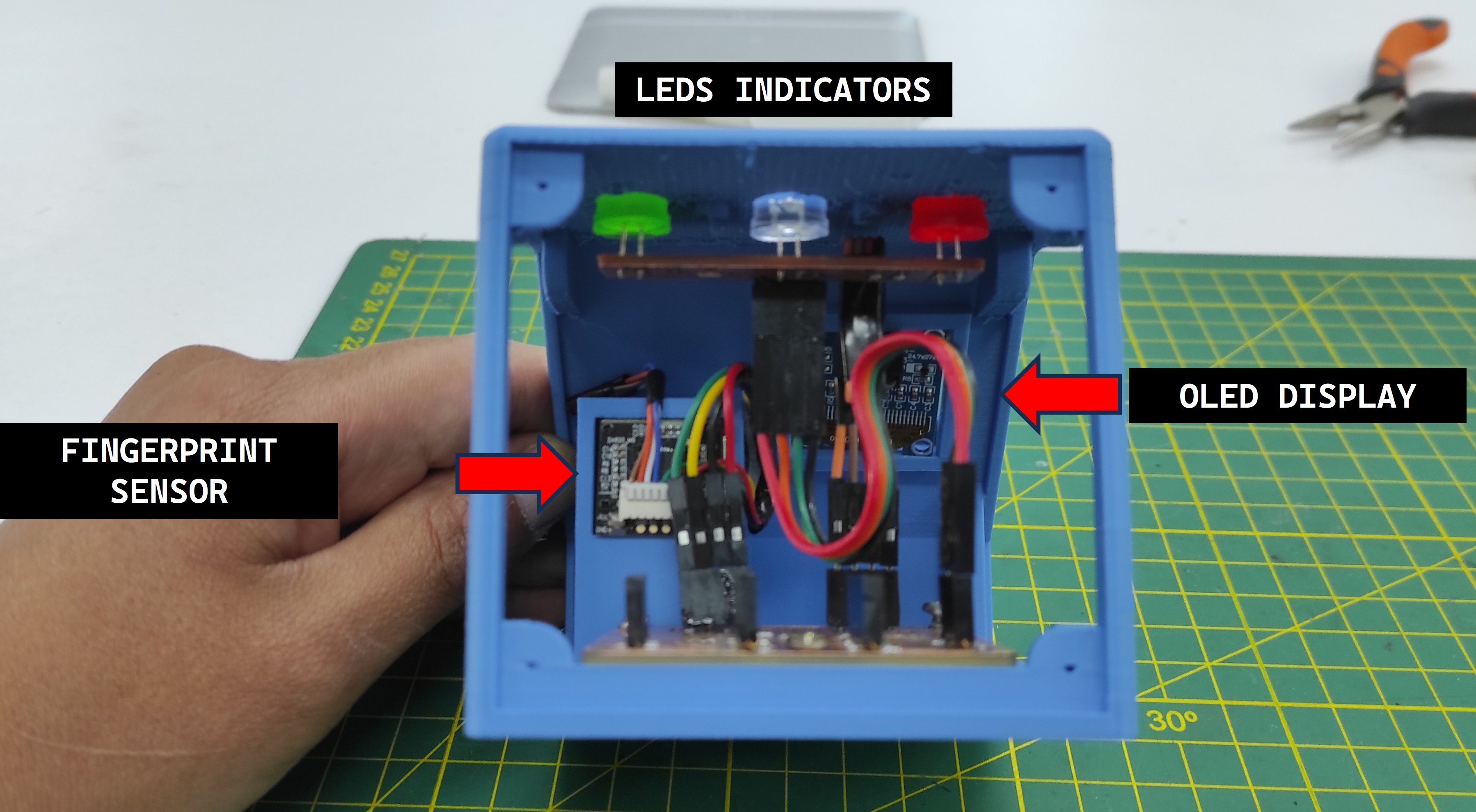
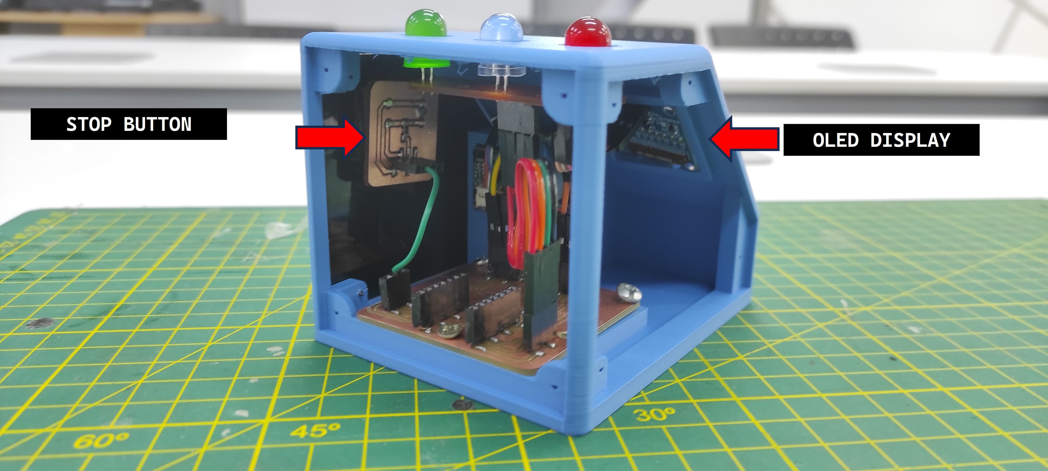
After testing the hardware integration, I proceeded to the mechanical integration phase, where I assembled all the components into a compact and functional prototype.
I designed a custom enclosure to securely house the components while ensuring proper alignment, organization, and protection of the system.
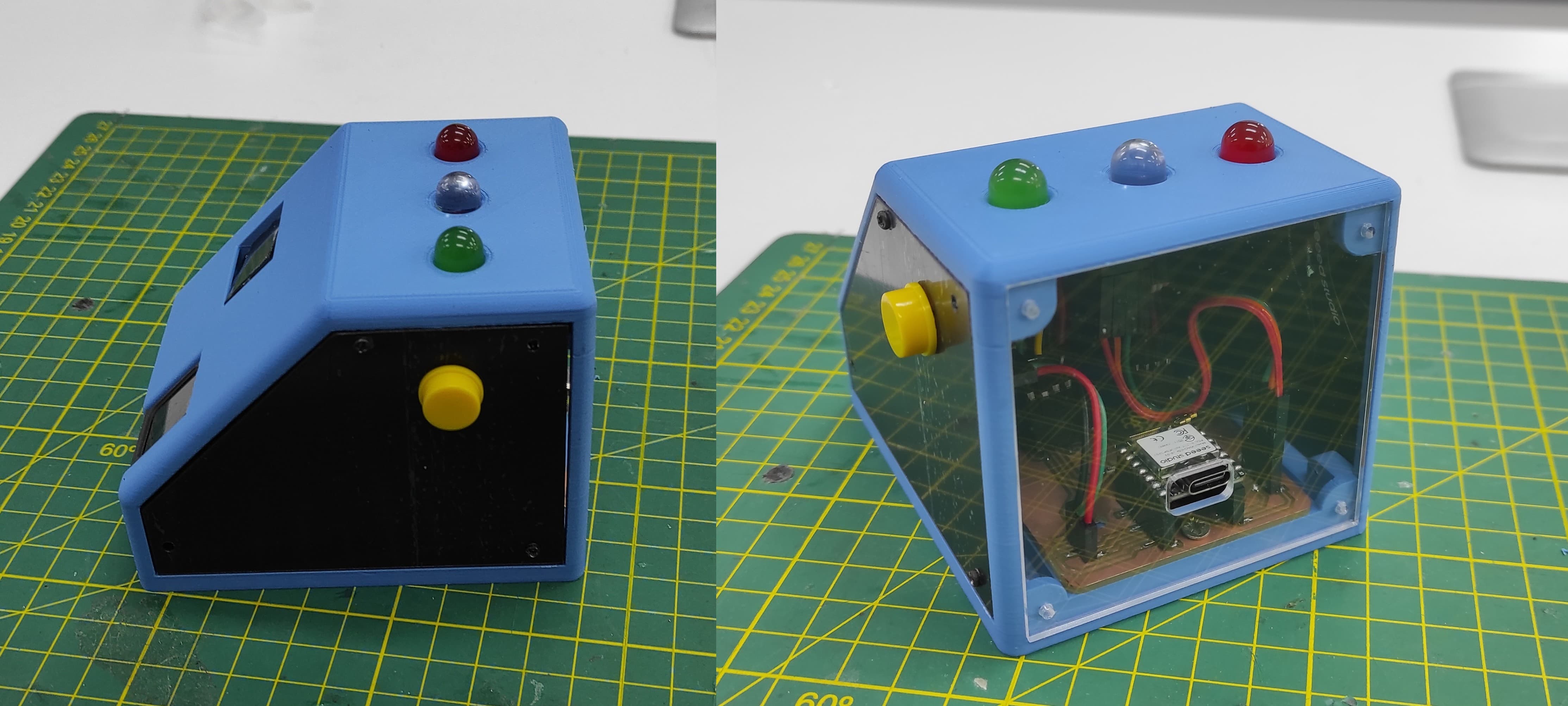
I assemblied all the parts into it and tested the final assembly.I assembled all the components into the enclosure and tested the final assembly to verify proper integration and functionality.
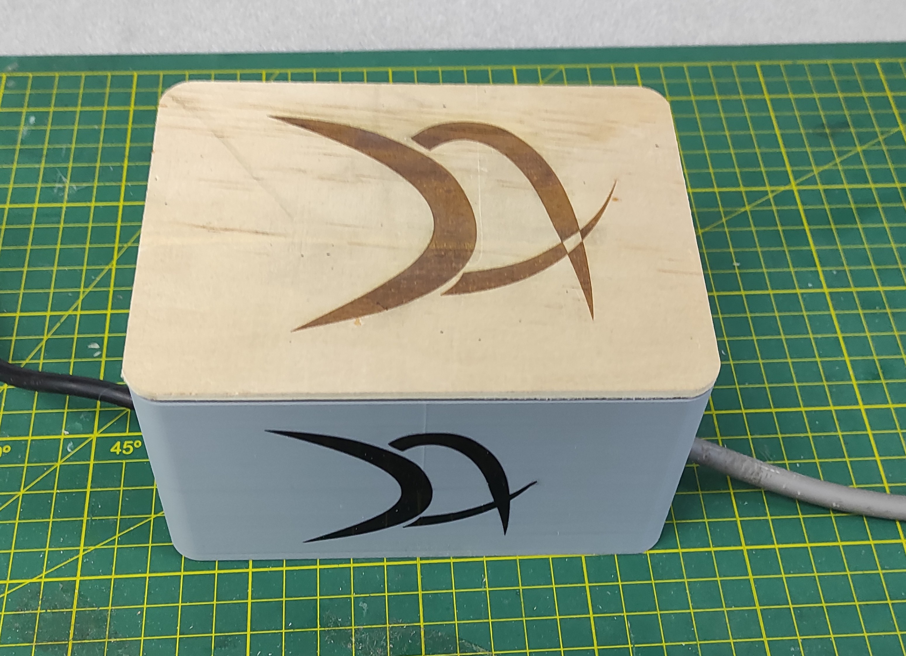
After the assembly, this is how the final system looks.
For the Power Control PCB Enclosure, I designed a custom case to house the power components and ensure proper accessibility.
After assembly, the solid-state relay was also installed inside the enclosure, allowing both components to be housed within the same enclosure.
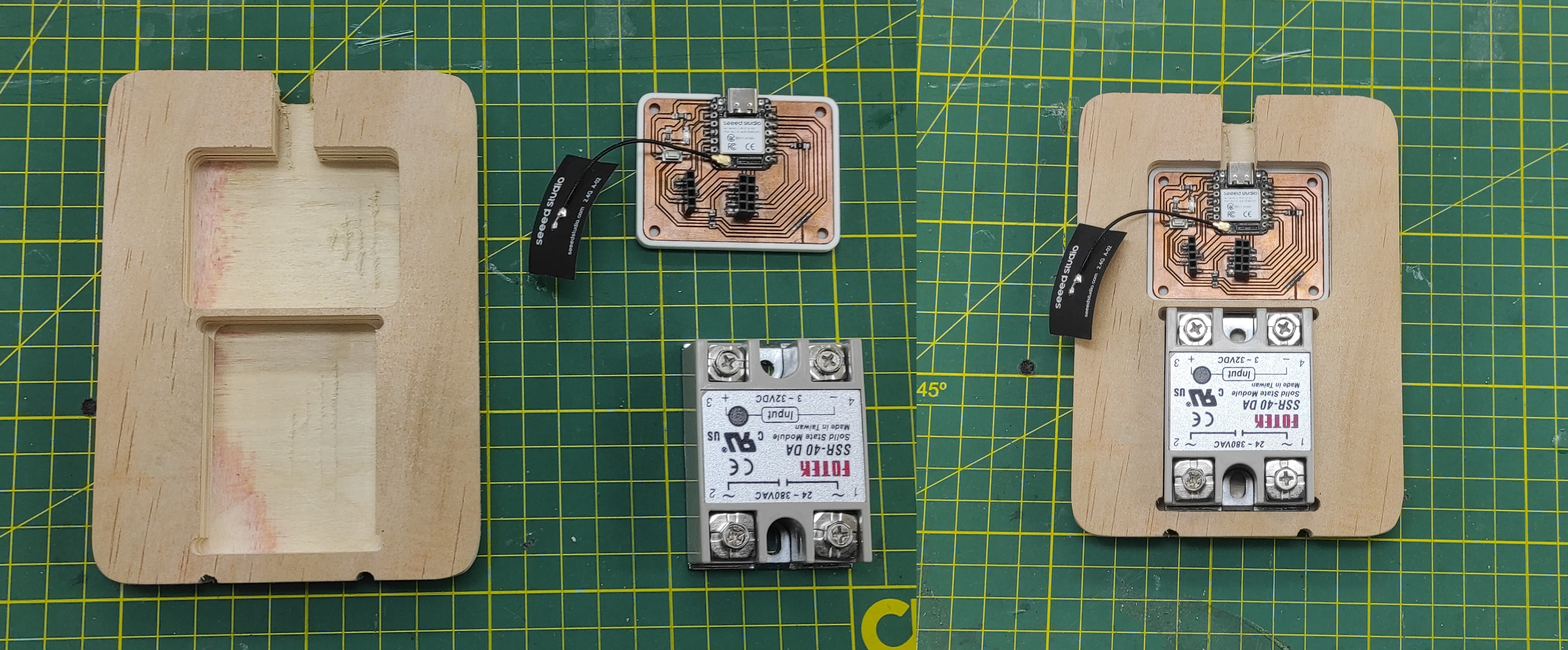
Once both components were ready, they were placed inside the second enclosure dedicated to the Power Control system.
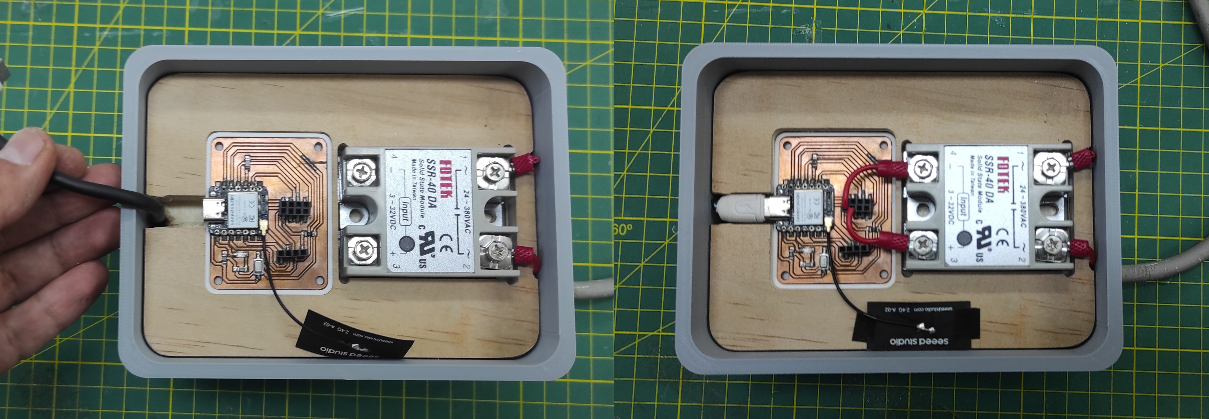
Finally, the complete system was assembled, with both the control and power blocks integrated into a single compact unit.
5. Learnings
During this system integration assignment, I learned the importance of carefully planning the interaction between the control and power blocks to ensure reliable communication and stable operation. Testing each module independently before integrating the complete system helped simplify debugging and identify issues more efficiently. I also understood the importance of proper power distribution, grounding, and firmware synchronization for achieving stable performance. Additionally, documenting the integration process and performing iterative testing were essential for improving the reliability and functionality of the final prototype.
6. Files
Here are the files available for download.