Week 11 Progress Checklist
| Status | Task |
|---|---|
| ✓ | Linked to the group assignment page |
| ✓ | Documented your project and what you have learned from implementing networking and/or communication protocols. |
| ✓ | Explained the programming process(es) you used. |
| ✓ | Ensured and documented that your addressing for boards works |
| ✓ | Outlined problems and how you fixed them. |
| ✓ | Included design files (or linked to where they are located if you are using a board you have designed and fabricated earlier) and original source code. |
| ✓ | Included a ‘hero shot’ of your board. |
Networking and Communications
Group Assignment
1. Microcontroller Communication Protocols
Microcontroller communication protocols are the fundamental building blocks that enable microcontrollers to exchange data with sensors, actuators, memory devices, and other microcontrollers. These protocols can be classified according to multiple criteria, each defining how devices interact, synchronize, and transfer information. The table below presents a brief classification organized by transmission direction (simplex, half-duplex, full-duplex), timing (synchronous, asynchronous), topology (point-to-point, bus, star, mesh), physical medium (wired single-ended, wired differential, wireless), speed (from very low to very high), and power consumption (ultra low to high). This overview helps engineers and hobbyists select the most appropriate protocol for their specific application requirements.
| Category | Subcategory / Protocols | Description / Characteristics |
|---|---|---|
| 📊 TRANSMISSION DIRECTION | 🔹 Simplex (One-way only) |
Protocols: I²S Output, PDM, PWM, DAC, ADC Application: Digital audio, MEMS microphones, motor control, analog/digital conversion |
| 🔸 Half-Duplex (Two-way, alternating) |
Protocols: I²C, CAN, RS-485, 1-Wire, LIN Application: Sensors, automotive, industrial, bus communication |
|
| 🔹 Full-Duplex (Two-way, simultaneous) |
Protocols: SPI, UART, Ethernet, USB, RS-422 Application: High speed, debugging, networking, PC peripherals |
|
| ⏱️ TIMING | 🔹 Synchronous (Shared clock signal) |
Protocols: SPI, I²C, I²S, JTAG, SDIO Arbitration: Master-Slave Feature: Dedicated clock line (SCK/SCL), higher speed |
| 🔸 Asynchronous (No shared clock) |
Start/Stop bits: UART, RS-232, RS-485 Line encoding: USB, Ethernet, CAN Arbitration: Multi-Master (CAN), CSMA/CD (Ethernet), CSMA/CA (Wi-Fi) |
|
| 🔗 TOPOLOGY | 🔹 Point-to-Point | UART, SPI (1 slave), USB |
| 🔸 Bus | I²C, CAN, RS-485, 1-Wire | |
| 🔹 Star | Ethernet (switch), USB (hub), SPI (multiple CS lines) | |
| 🔸 Mesh | Zigbee, Thread, BLE Mesh | |
| 🔌 PHYSICAL MEDIUM | 🔹 Wired Single-ended | UART (TTL), SPI, I²C, 1-Wire |
| 🔸 Wired Differential | CAN, RS-485, Ethernet, USB, LVDS | |
| 🔹 Wireless | Wi-Fi, BLE, Zigbee, LoRa, Thread | |
| ⚡ SPEED | 🔹 Very Low (<100 kbps) | 1-Wire, LIN, I²C Standard |
| 🔸 Low (100 kbps - 1 Mbps) | I²C Fast, CAN, RS-485 (long range) | |
| 🔹 Medium (1 - 50 Mbps) | SPI, USB 1.1, CAN-FD | |
| 🔸 High (50 - 480 Mbps) | USB 2.0, Ethernet 100M | |
| 🔹 Very High (>480 Mbps) | USB 3.x, Gigabit Ethernet, PCIe | |
| 🔋 POWER CONSUMPTION | 🔹 Ultra Low (µW - mW) |
Continuous operation: 1-Wire, I²C (Standard mode), LIN With sleep modes: BLE, LoRa, Zigbee, Thread Application: Battery-powered IoT, remote sensors, wearables, medical implants |
| 🔸 Low (mW - hundreds mW) |
In operation: UART (low speed), SPI (low speed), I²C Fast mode Power management: CAN (standby), RS-485 (idle) Application: Portable embedded systems, automotive, instrumentation |
|
| 🔹 Medium (1 - 5 W) |
Active operation: USB 2.0, Ethernet 100M, Wi-Fi (transmitting) CAN active, RS-485 active Application: USB-powered devices, industrial control systems, gateways |
|
| 🔸 High (>5 W) |
In operation: Gigabit Ethernet, USB 3.x, PCIe, High-power Wi-Fi With PoE: Devices powered over Ethernet cable Application: Servers, base stations, network equipment, high-speed systems |
1.1 Serial Peripheral Interface (SPI)
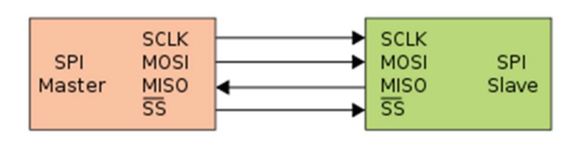
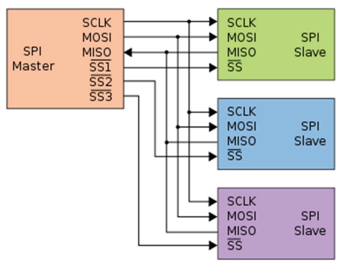
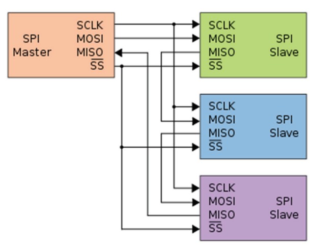
Serial Peripheral Interface (SPI) is an interface bus commonly used to send data between microcontrollers and small peripherals such as shift registers, sensors, and SD cards. It uses separate clock and data lines, along with a select line to choose the device you wish to talk to.
SPI (Serial Peripheral Interface) is a synchronous, full-duplex communication protocol developed by Motorola in the 1980s. It is one of the most widely used protocols for short-distance, high-speed communication between microcontrollers and peripheral devices.
| Signal | Name | Direction | Function |
|---|---|---|---|
| SCK | Serial Clock | Master → Slave | Clock signal generated by master to synchronize data |
| MOSI | Master Out Slave In | Master → Slave | Data line from master to slave |
| MISO | Master In Slave Out | Slave → Master | Data line from slave to master |
| CS/SS | Chip Select / Slave Select | Master → Slave | Active-low signal to select which slave to communicate with |
| Single master multiple slaves | Master and cooperative slaves |
|---|---|
 |
 |
1.2 SPI between Arduino UNO and ESP32
I am going to test SPI communication between an Arduino Uno and an ESP32. In this setup, the ESP32 will act as the master, while the Arduino Uno will be configured as the slave.
The ESP32 will have a button connected to it, and the Arduino Uno will control an LED. When the button on the ESP32 is pressed, it will send a signal via SPI to the Arduino Uno to turn the LED on or off.
This setup will demonstrate basic master–slave communication using the SPI protocol.
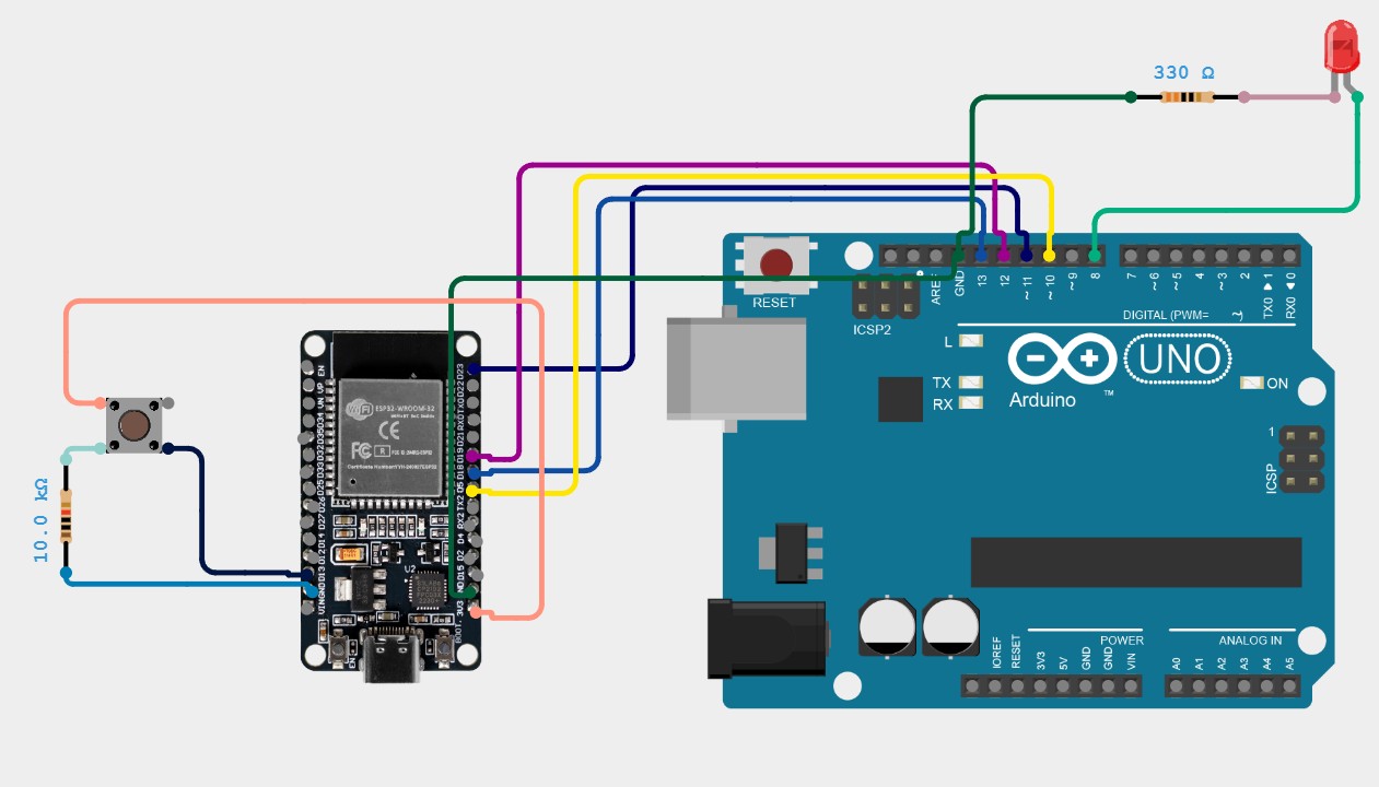
This code configures the Arduino UNO as an SPI slave device that waits for commands from the ESP32 master. In the setup, it initializes the SPI pins (MISO as output, MOSI, SCK, and SS as inputs) and enables SPI in slave mode using the SPCR register. The loop continuously checks the SPI Status Register (SPSR) for the SPIF flag, which indicates that data has been received. When a command arrives, it reads the byte from the SPI Data Register (SPDR), then checks if the value is 0x01 (turn LED on) or 0x00 (turn LED off), and controls the LED on pin 8 accordingly. Finally, it echoes the same command back to the master as an acknowledgment, completing the communication cycle.
// Generated with ChatGPT (OpenAI)
// Prompt:
// Arduino UNO SPI Slave code that receives commands from an SPI Master. Turn an LED on pin 8 ON when receiving 0x01 and OFF when receiving 0x00, print the status to the Serial Monitor, and echo the received byte back to the master.

        #include <SPI.h>

        // LED pin definition
        const int ledPin = 8;
        volatile byte receivedCommand = 0;
        volatile bool newCommand = false;

        void setup() {

        Serial.begin(9600);
        pinMode(ledPin, OUTPUT);
        digitalWrite(ledPin, LOW);

        // Configure SPI pins
        pinMode(MISO, OUTPUT);
        pinMode(MOSI, INPUT);
        pinMode(SCK, INPUT);
        pinMode(SS, INPUT);

        // SPI configuration: Enable SPI, Slave Mode, MSB First, Mode 0
        SPCR = (1 << SPE);  // SPE = 1 (enable SPI), MSTR = 0 (slave mode)

        Serial.println("Arduino UNO SPI Slave Ready");
        }

        void loop() {

        // Check if data is available in the SPI buffer
        if (SPSR & (1 << SPIF)) {

            // Read the received byte
            receivedCommand = SPDR;

            // Process the command
            if (receivedCommand == 0x01) {
            digitalWrite(ledPin, HIGH);
            Serial.println("LED TURNED ON");
            }
            else if (receivedCommand == 0x00) {
            digitalWrite(ledPin, LOW);
            Serial.println("LED TURNED OFF");
            }

            // Send the same byte back as response (echo)
            SPDR = receivedCommand;
        }

        delay(10);
        }
This code configures the ESP32 as an SPI master that monitors a button and sends commands to control the LED on the Arduino UNO. The setup initializes the SPI bus with a frequency of 500 kHz, Mode 0, and MSB First, and configures pin 13 as an input with a pull-down resistor to detect button presses. In the main loop, it reads the button state and uses debouncing logic to detect a valid press (transition from LOW to HIGH). When a button press is detected, it toggles the LED state and calls the sendSPICommand function, which pulls the Slave Select (CS) pin LOW to select the Arduino UNO, transmits the command byte (0x01 for ON, 0x00 for OFF) via SPI.transfer(), and then pulls CS HIGH to deselect the slave, effectively controlling the remote LED with each button press.
// Generated with ChatGPT (OpenAI)
// Prompt:
// ESP32 SPI Master code that uses a push button on pin 13 to control an Arduino UNO SPI Slave. When the button is pressed, toggle the LED state by sending command 0x01 (ON) or 0x00 (OFF) via SPI, using VSPI pins and displaying status messages in the Serial Monitor.

        #include <SPI.h>

        // SPI pins for ESP32
        #define VSPI_MISO 19
        #define VSPI_MOSI 23
        #define VSPI_SCLK 18
        #define VSPI_SS   5

        // Button pin
        const int buttonPin = 13;
        bool lastButtonState = LOW;
        bool ledState = false;

        void setup() {

        Serial.begin(115200);
        delay(1000);

        // Configure button pin
        pinMode(buttonPin, INPUT_PULLDOWN);

        // Configure CS pin
        pinMode(VSPI_SS, OUTPUT);
        digitalWrite(VSPI_SS, HIGH);

        // Initialize SPI
        SPI.begin(VSPI_SCLK, VSPI_MISO, VSPI_MOSI, VSPI_SS);
        SPI.setFrequency(500000);
        SPI.setDataMode(SPI_MODE0);
        SPI.setBitOrder(MSBFIRST);

        Serial.println("ESP32 SPI Master Ready");
        Serial.println("Press the button to control the LED");
        }

        void loop() {

        // Read button state
        bool currentButtonState = digitalRead(buttonPin);

        // Check for button press (transition from LOW to HIGH)
        if (currentButtonState == HIGH && lastButtonState == LOW) {

            delay(50); // Debounce delay

            // Confirm button press after debounce
            if (digitalRead(buttonPin) == HIGH) {

            ledState = !ledState; // Toggle LED state

            if (ledState) {
                Serial.println("Button pressed - TURNING LED ON");
                sendSPICommand(0x01);
            }
            else {
                Serial.println("Button pressed - TURNING LED OFF");
                sendSPICommand(0x00);
            }
            }
        }

        lastButtonState = currentButtonState;
        delay(10);
        }

        void sendSPICommand(byte command) {

        // Select the slave (Arduino UNO)
        digitalWrite(VSPI_SS, LOW);
        delayMicroseconds(5);

        // Send command via SPI
        SPI.transfer(command);

        delayMicroseconds(5);

        // Deselect the slave
        digitalWrite(VSPI_SS, HIGH);
        }
Individual Assignment
2. Connecting Projects
For this assignment, I will be using two boards that I previously designed. Their design and manufacturing processes can be found in Assignments 6 and 8.
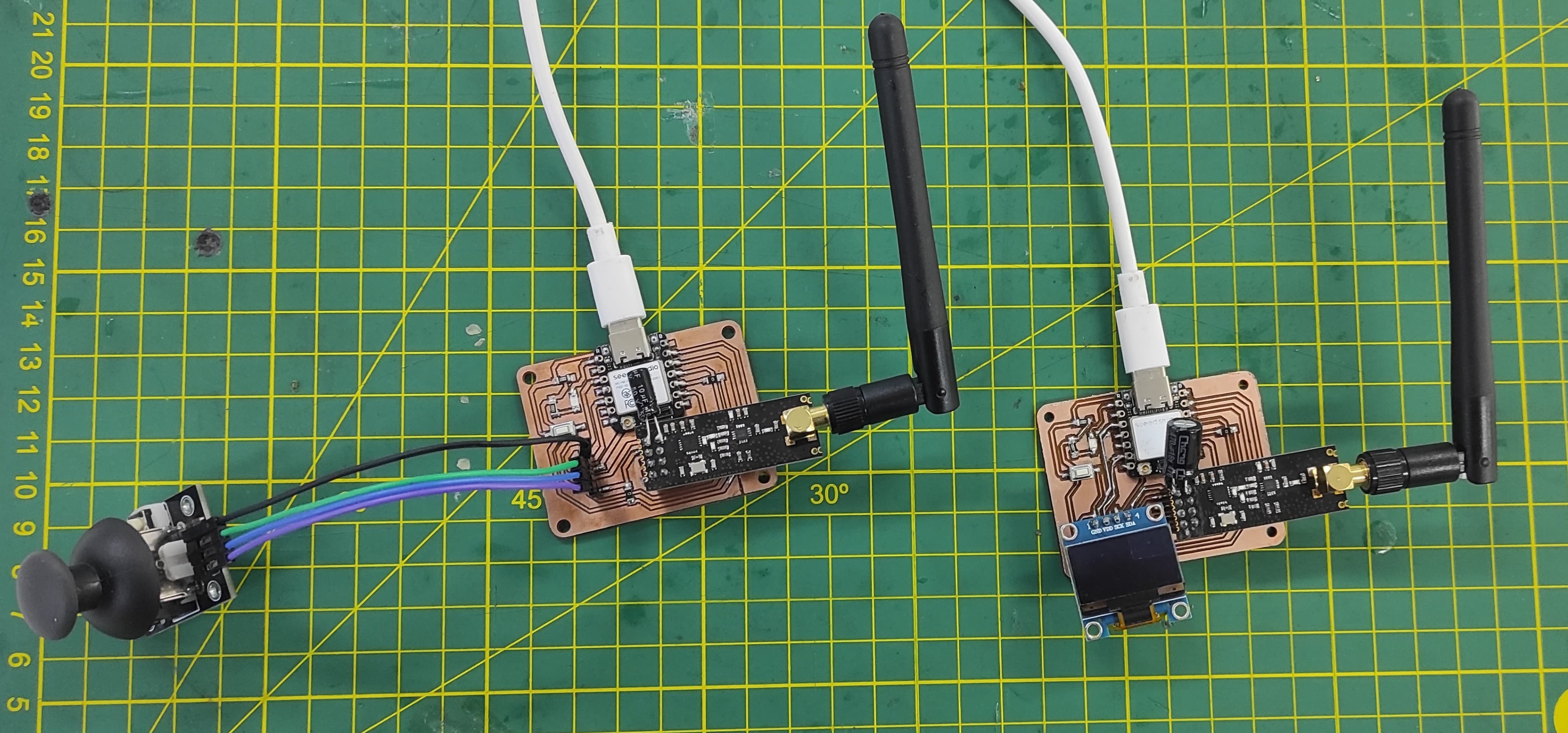
Connecting Projects - Joystick and Oled Display
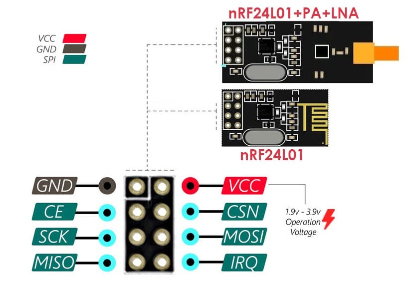
The nRF24L01 is a low-power, 2.4GHz wireless transceiver module commonly used for communication between microcontrollers like Arduino and ESP32. It supports multiple channels, allows up to 6 devices to communicate in a star network, and can transmit data at speeds up to 2 Mbps over distances of up to 100 meters (or more with an external antenna). It communicates via SPI (Serial Peripheral Interface) and requires a stable 3.3V power supply to function reliably—making proper power regulation and decoupling essential for stable operation.
Connecting Projects - Joystick and Oled Display
Code for the Transmitter
This Arduino code sets up the board as an SPI slave device that listens for commands from an SPI master to control an LED connected to pin 8. In the setup, it initializes serial communication for debugging, configures the LED pin as an output, and properly sets the SPI pins with MISO as output and the others as inputs, then enables SPI in slave mode. In the main loop, it continuously checks if a byte has been received via SPI, reads it, and turns the LED ON if the command is 0x01 or OFF if it is 0x00, while also printing the action to the serial monitor. After processing, it sends the same byte back to the master as an echo response.
// Generated with ChatGPT (OpenAI)
// Prompt:
// Arduino code for a XIAO ESP32-S3 with an NRF24L01 module and a joystick. Read the X and Y analog values from the joystick, store them in a structure, and transmit the data wirelessly every 50 ms using the RF24 library. Print the transmitted values to the Serial Monitor for debugging.

        // NRF24L01 Transmisor con Joystick y XIAO ESP32-S3
        // Envía valores X e Y del joystick de forma inalámbrica

        #include <SPI.h>
        #include <RF24.h>
        #include <Wire.h>

        // Definir pines del NRF24L01
        #define CE_PIN D2
        #define CSN_PIN D3

        // Pines del joystick
        #define JOYSTICK_X D4
        #define JOYSTICK_Y D5

        // Crear objeto radio
        RF24 radio(CE_PIN, CSN_PIN);
        const byte address[6] = "00001";

        // Estructura para enviar datos del joystick
        struct JoystickData {
        int xValue;
        int yValue;
        bool buttonPressed;
        };

        JoystickData joystickData;

        unsigned long lastSendTime = 0;
        const unsigned long sendInterval = 50;

        void setup() {

        Serial.begin(115200);

        // Configurar pines del joystick
        pinMode(JOYSTICK_X, INPUT);
        pinMode(JOYSTICK_Y, INPUT);

        // Inicializar módulo NRF24L01
        if(!radio.begin()) {
            Serial.println("Error: Radio no responde!");
            while(1);
        }

        radio.openWritingPipe(address);
        radio.setPALevel(RF24_PA_MIN);
        radio.setDataRate(RF24_250KBPS);
        radio.stopListening();

        Serial.println("Transmisor Joystick iniciado");
        }

        void loop() {

        // Leer valores del joystick
        joystickData.xValue = analogRead(JOYSTICK_X);
        joystickData.yValue = analogRead(JOYSTICK_Y);

        // Enviar datos cada cierto intervalo
        if((millis() - lastSendTime) >= sendInterval) {

            lastSendTime = millis();

            // Enviar estructura completa
            bool result = radio.write(&joystickData, sizeof(JoystickData));

            // Debug por Serial
            Serial.print("X: ");
            Serial.print(joystickData.xValue);
            Serial.print(" | Y: ");
            Serial.println(joystickData.yValue);

            if(!result) {
                Serial.println("Fallo al enviar");
            }
        }

        delay(10);
        }
Code for the Receiver
This code implements an Arduino Uno acting as an SPI slave that receives simple commands from a master device to control an LED. It initializes serial communication for monitoring, configures the SPI hardware in slave mode, and sets the appropriate pin directions. During execution, it continuously checks for incoming SPI data, reads the received byte, and interprets it to turn the LED on (0x01) or off (0x00). After handling the command, it sends the same byte back to the master as a confirmation. The use of direct register manipulation makes the SPI communication efficient, though the added delay slightly slows responsiveness.
// Generated with ChatGPT (OpenAI)
// Prompt:
// Arduino code for a XIAO ESP32-S3 with an NRF24L01 receiver and a 128x64 SSD1306 OLED display. Receive joystick X and Y values sent wirelessly from another NRF24L01 module, display the values and percentages on the OLED, show the joystick position graphically, print the received data to the Serial Monitor, and display a timeout message if no data is received for 500 ms.

        // NRF24L01 Receptor con OLED y XIAO ESP32-S3
        // Recibe datos del joystick y los muestra en pantalla SSD1306

        #include <SPI.h>
        #include <RF24.h>
        #include <Wire.h>
        #include <Adafruit_SSD1306.h>
        #include <Adafruit_GFX.h>

        // Definir pines del NRF24L01
        #define CE_PIN D2
        #define CSN_PIN D3

        // Configuración del OLED
        #define SCREEN_WIDTH 128
        #define SCREEN_HEIGHT 64
        #define OLED_RESET -1
        #define OLED_ADDRESS 0x3C

        // Crear objeto radio
        RF24 radio(CE_PIN, CSN_PIN);
        const byte address[6] = "00001";

        // Crear objeto display
        Adafruit_SSD1306 display(SCREEN_WIDTH, SCREEN_HEIGHT, &Wire, OLED_RESET);

        // Estructura de datos del joystick
        struct JoystickData {
        int xValue;
        int yValue;
        bool buttonPressed;
        };

        JoystickData joystickData;

        unsigned long lastReceiveTime = 0;
        const unsigned long timeout = 500;

        int lastX = 0;
        int lastY = 0;

        void setup() {

        Serial.begin(115200);

        // Inicializar I2C
        Wire.begin(D4, D5);

        // Inicializar OLED
        if(!display.begin(SSD1306_SWITCHCAPVCC, OLED_ADDRESS)) {
            Serial.println("Error: OLED no encontrado!");
            while(1);
        }

        display.clearDisplay();
        display.setTextSize(1);
        display.setTextColor(SSD1306_WHITE);
        display.setCursor(0, 0);
        display.println("Esperando datos...");
        display.display();

        // Inicializar radio
        if(!radio.begin()) {
            Serial.println("Error: Radio no responde!");
            while(1);
        }

        radio.openReadingPipe(0, address);
        radio.setPALevel(RF24_PA_MIN);
        radio.setDataRate(RF24_250KBPS);
        radio.startListening();

        Serial.println("Receptor OLED iniciado");
        }

        void loop() {

        // Verificar datos disponibles
        if(radio.available()) {

            radio.read(&joystickData, sizeof(JoystickData));
            lastReceiveTime = millis();

            displayJoystickValues(joystickData.xValue, joystickData.yValue);

            Serial.print("Recibido - X: ");
            Serial.print(joystickData.xValue);
            Serial.print(" | Y: ");
            Serial.println(joystickData.yValue);
        }

        // Verificar timeout
        if((millis() - lastReceiveTime) > timeout) {

            display.clearDisplay();
            display.setCursor(0, 0);
            display.println("Sin conexion!");
            display.println("Esperando...");
            display.display();
        }

        delay(10);
        }

        // Mostrar valores del joystick en OLED
        void displayJoystickValues(int x, int y) {

        display.clearDisplay();

        display.setTextSize(1);
        display.setCursor(0, 0);
        display.println("Joystick Values");
        display.drawLine(0, 10, 128, 10, SSD1306_WHITE);

        display.setCursor(0, 15);
        display.print("X: ");
        display.println(x);

        display.setCursor(0, 25);
        display.print("Y: ");
        display.println(y);

        int xPercent = map(x, 0, 4095, 0, 100);
        int yPercent = map(y, 0, 4095, 0, 100);

        display.setCursor(0, 35);
        display.print("X%: ");
        display.print(xPercent);
        display.println("%");

        display.setCursor(0, 45);
        display.print("Y%: ");
        display.print(yPercent);
        display.println("%");

        int displayX = map(x, 0, 4095, 10, 118);
        int displayY = map(y, 0, 4095, 54, 10);

        display.fillCircle(displayX, displayY, 3, SSD1306_WHITE);
        display.drawCircle(displayX, displayY, 4, SSD1306_WHITE);

        display.drawLine(64, 54, 64, 10, SSD1306_WHITE);
        display.drawLine(10, 32, 118, 32, SSD1306_WHITE);

        display.display();
        }
Projects connected
We can now see how the OLED display shows the position of the joystick, updating in real time as the joystick moves.
3. Learnings
For the nRF24L01, the key learning across Arduino Uno, ESP32, and XIAO ESP32 is that stable 3.3V power is critical—always use a decoupling capacitor (10–100µF) across VCC and GND to prevent glitches. The Arduino Uno has fixed SPI pins (11, 12, 13) and requires the module's VCC connected to its 3.3V pin. ESP32 and XIAO ESP32 offer flexible SPI pin assignment via software, but still need clean 3.3V power. Never connect the module to 5V on any board.
4. Files
Here are the files available for download.