Week 10 Progress Checklist
| Status | Task |
|---|---|
| ✓ | Linked to the group assignment page |
| ✓ | Documented how you determined power consumption of an output device with your group. |
| ✓ | Documented what you learned from interfacing output device(s) to microcontroller and controlling the device(s). |
| ✓ | Linked to the board you made in a previous assignment or documented your design and fabrication process if you made a new board. |
| ✓ | Explained how your code works. |
| ✓ | Explained any problems you encountered and how you fixed them. |
| ✓ | Included original source code and any new design files. |
| ✓ | Included a ‘hero shot’ of your board. |
Output Devices
Group Assignment
1. Power consumption of an output device.
Measuring the power consumption of a device is fundamentally based on electrical theory and can be accomplished through several methods, with the choice depending on the device type, accuracy requirements, and available tools.
⚡ 1.1 The Basic Formula: The Foundation of All Power Measurements
At its core, electrical power is calculated using Ohm's Law and the power equation:P = V × I
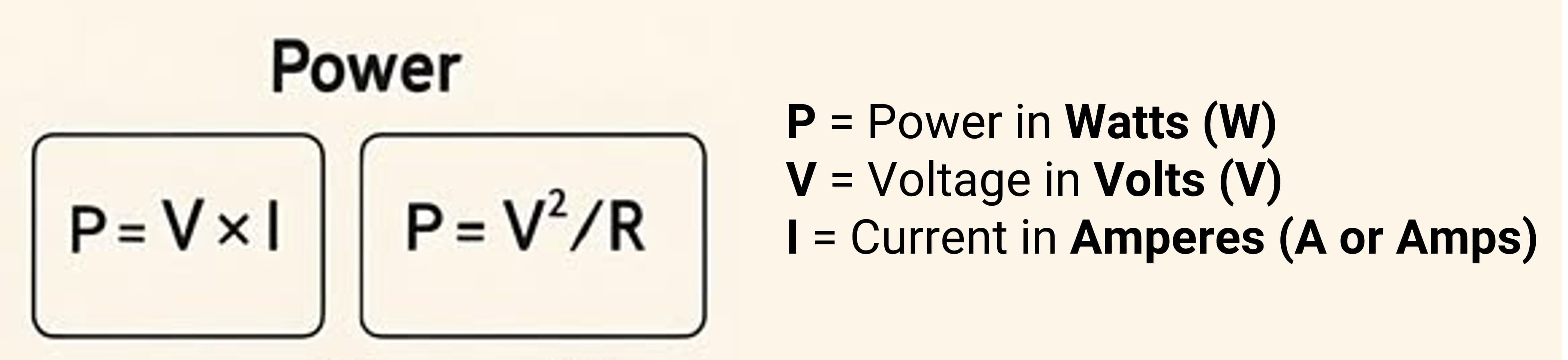
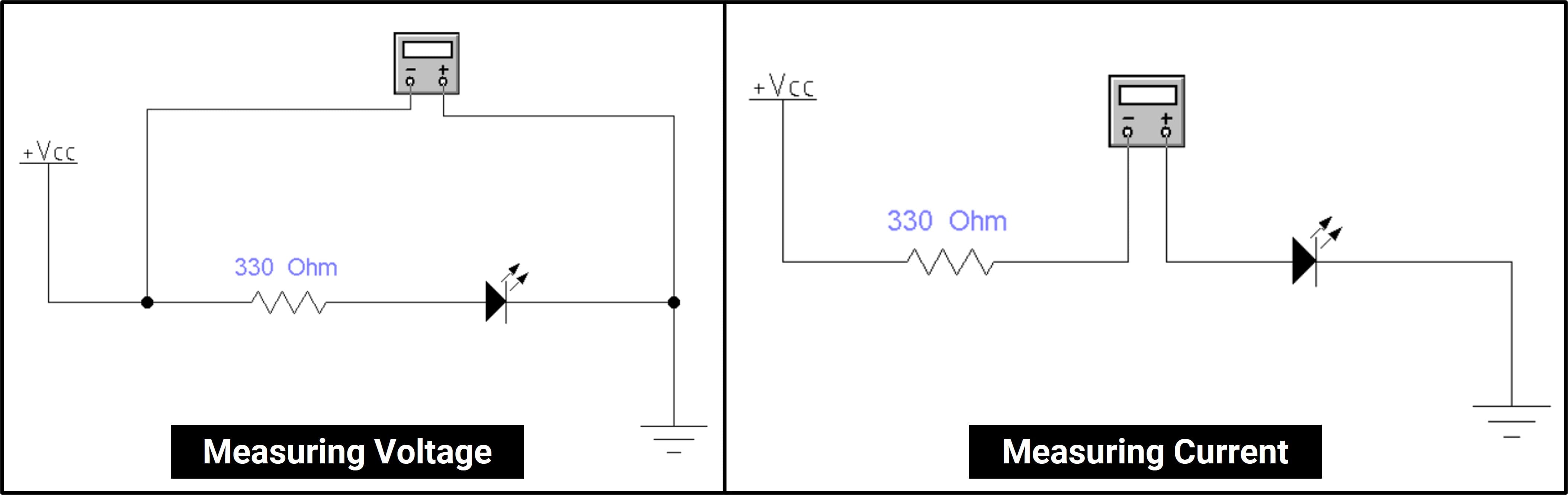
To measure voltage with a multimeter, connect probes in PARALLEL across the component.
to measure current (amperage) with a multimeter, Break the circuit and connect probes in SERIES.
1.2 Measuring the Power Consumption of an RGB LED
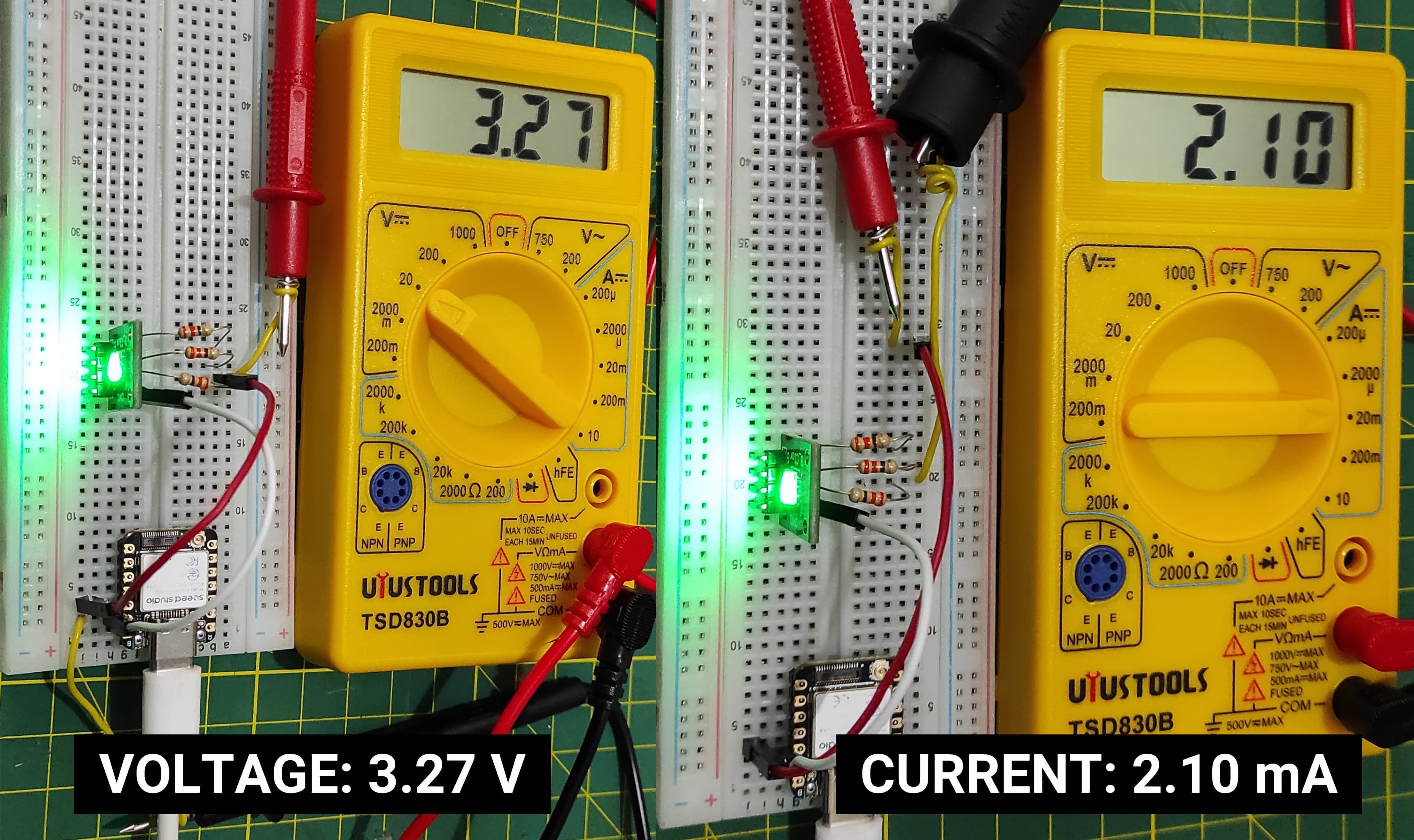
Now I am measuring the voltage and current of the green channel of the RGB LED.
|
Power Calculation P = V × I P = 3.27 V × 2.10 mA P = 6.87 mW |
 |
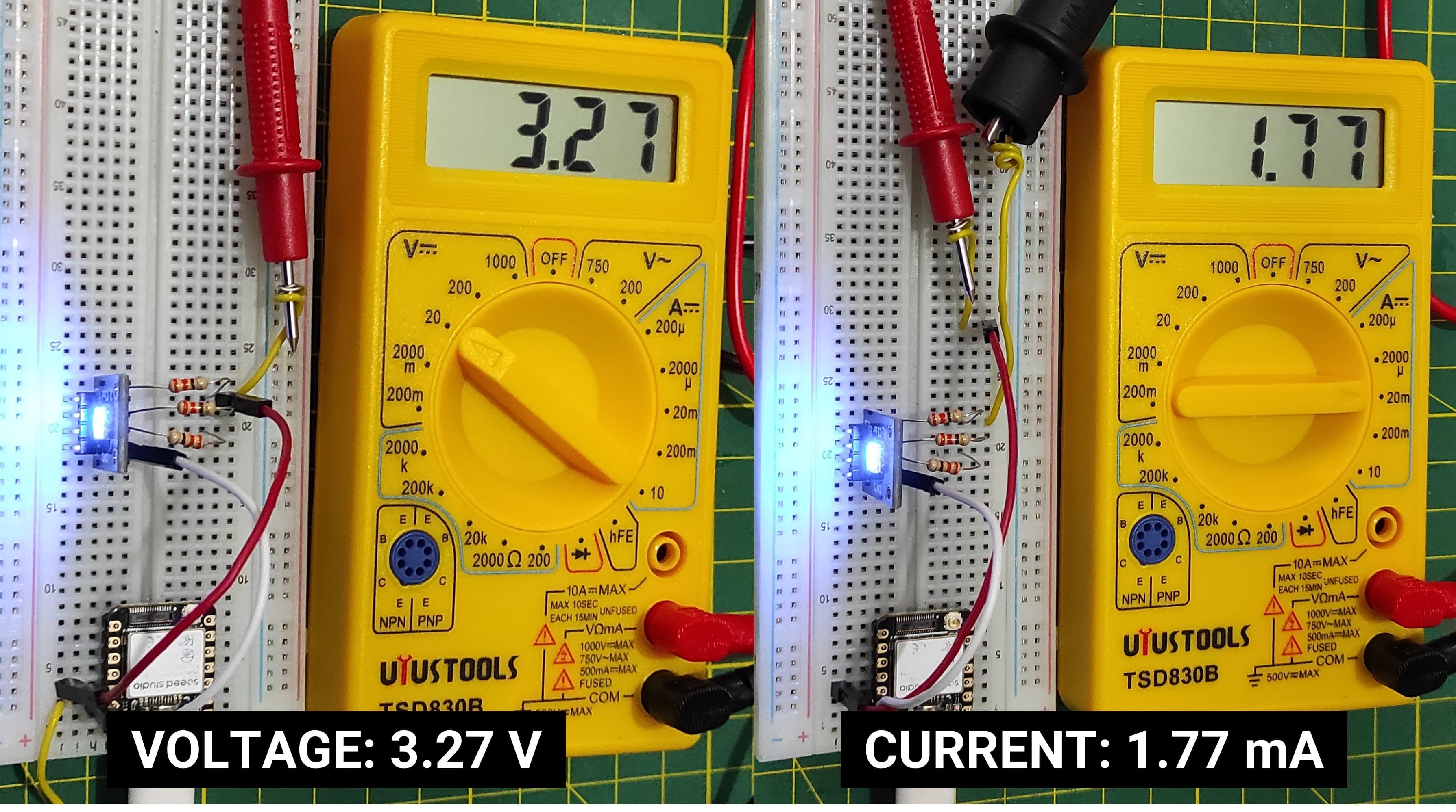
Now I am measuring the voltage and current of the green channel of the RGB BLUE.
|
Power Calculation P = V × I P = 3.27 V × 1.77 mA P = 5.79 mW |
 |
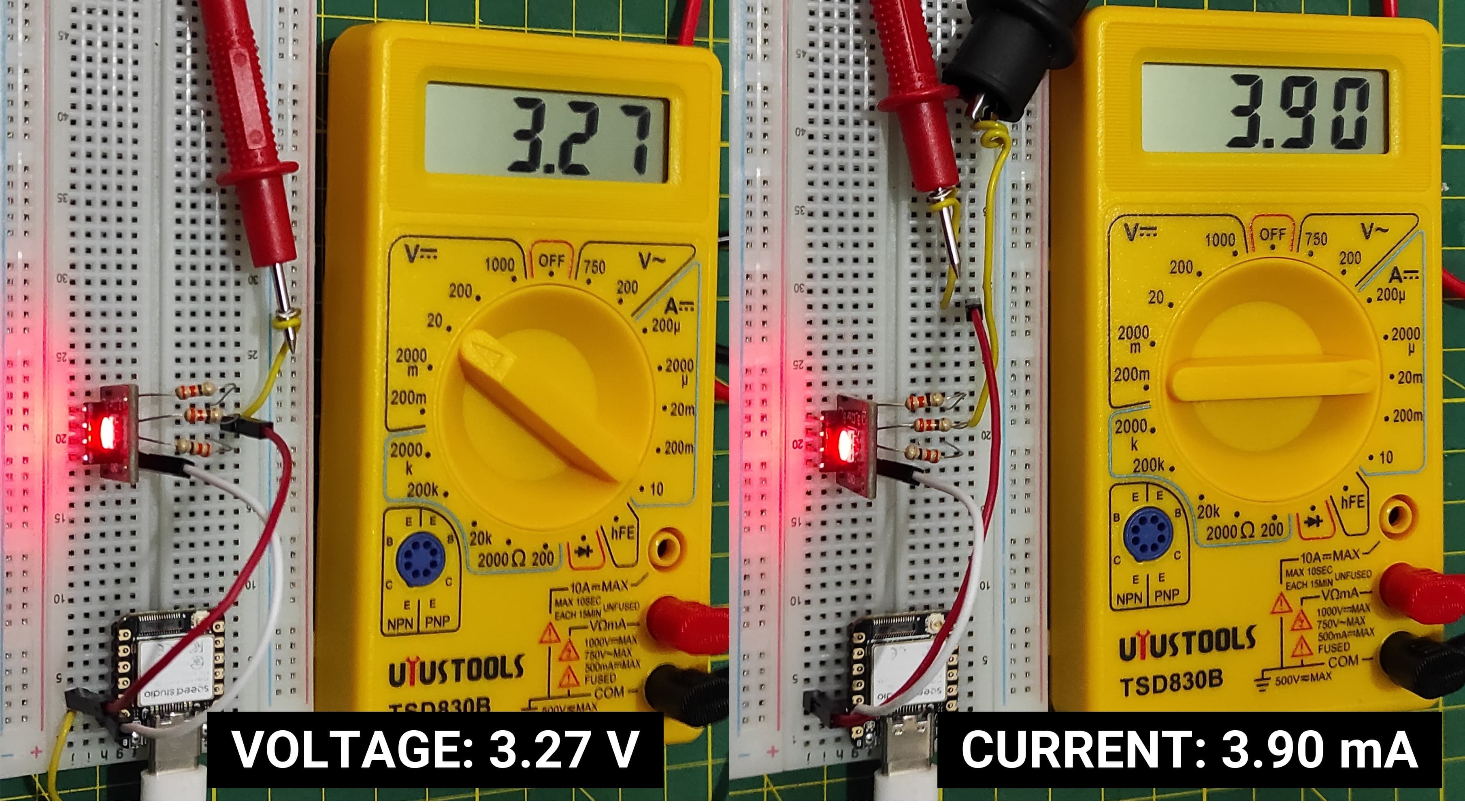
Now I am measuring the voltage and current of the green channel of the RGB RED.
|
Power Calculation P = V × I P = 3.27 V × 3.90 mA P = 12.75 mW |
 |
Individual Assignment
2. Working with Output Device and Microcontroller
2.1 Working with I2C Oled
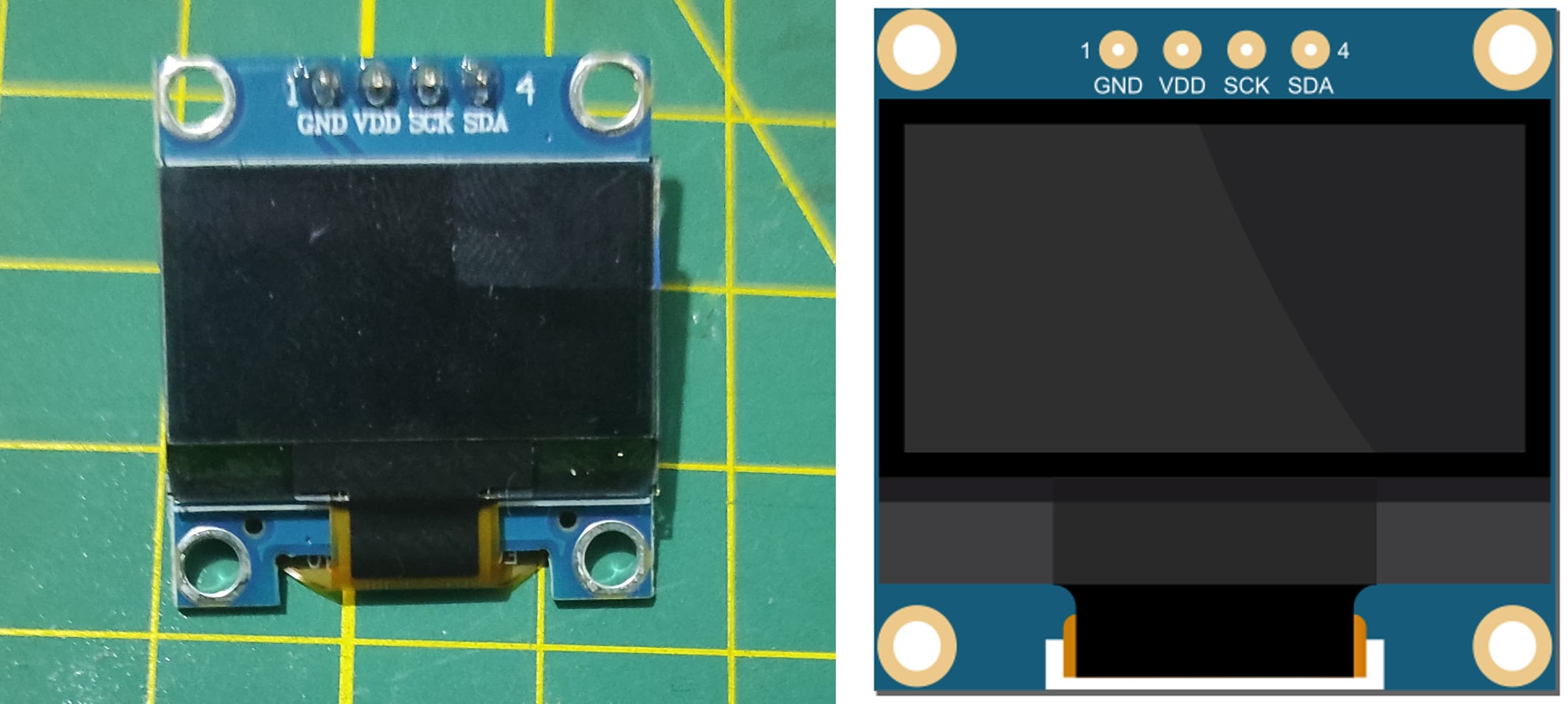
I2C OLED displays (commonly 0.96" or 1.3") are small, high-contrast, and energy-efficient monochrome screens used in DIY electronics. Controlled via the 2-wire I2C protocol (SDA/SCL), they typically use the SSD1306 driver IC to display 128x64 or 128x32 pixel graphics. They require only 4 pins (VCC, GND, SCL, SDA), making them ideal for Arduino, ESP32, and Raspberry Pi projects.
The organic light-emitting diode (OLED) display that we’ll use in this tutorial is the SSD1306 model: a monocolor, 0.96-inch display with 128×64 pixels as shown in the following figure.
The model we’re using here has only four pins and communicates with the Arduino using I2C communication protocol. There are models that come with an extra RESET pin. There are also other OLED displays that communicate using SPI communication.
2.2 Connections with XIA ESP32 S3
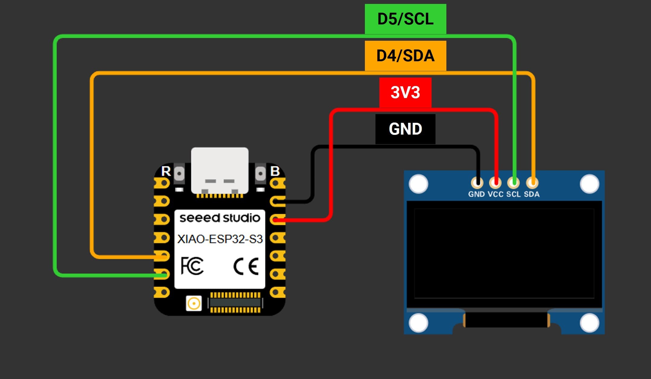
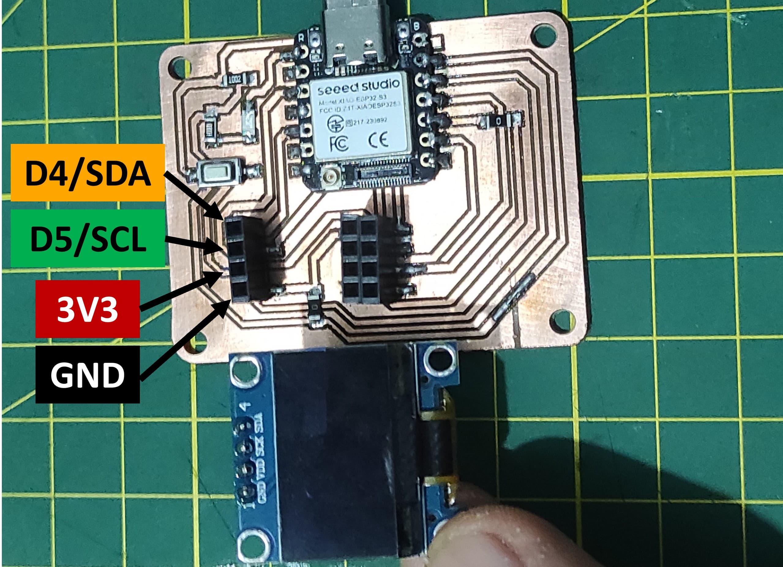
Because the OLED display uses I2C communication protocol, wiring is very simple. You just need to connect to the XIAO ESP32 S3 I2C pins as shown in the table below.
| Pin OLED | Wiring to XIAO ESP32 S3 |
|---|---|
| Vin | 3V3 |
| GND | GND |
| SCL | D5/SCL |
| SDA | D4/SDA |
To connect the I2C OLED display to the XIA ESP32 S3, follow these steps:
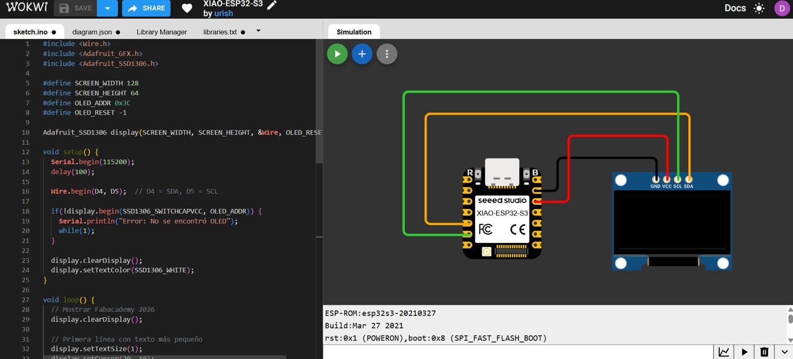
2.3 Simulation with Wokwi
I used Wokwi to run the simulation, which allowed me to try the simulator again and save some time.
How the code works - XIAO ESP32S3 Sense - OLED I2C
This code controls an OLED display (SSD1306) using a XIAO ESP32-S3 and Adafruit libraries. In the setup, it initializes serial communication, starts I2C communication with custom SDA and SCL pins, and initializes the OLED display, stopping the program if the display is not detected. In the loop, it alternates between two screens: first showing “Fabacademy 2026” with different text sizes, and then displaying the name “Daniel Haro.” Each screen is cleared, updated, and shown on the display, with a 3-second delay between transitions.
// Generated with ChatGPT (OpenAI)
// Prompt:
// Arduino code for a XIAO ESP32-S3 connected to a 128x64 SSD1306 OLED display via I2C. Use the Adafruit GFX and SSD1306 libraries to initialize the display and alternate every 3 seconds between showing "Fabacademy 2026" and the name "Daniel Haro".

        // OLED Display con XIAO ESP32-S3
        // Usa librerías Adafruit para controlar una pantalla SSD1306

        #include <Wire.h>
        #include <Adafruit_GFX.h>
        #include <Adafruit_SSD1306.h>

        // Configuración de la pantalla
        #define SCREEN_WIDTH 128
        #define SCREEN_HEIGHT 64
        #define OLED_ADDR 0x3C
        #define OLED_RESET -1

        // Crear objeto display
        Adafruit_SSD1306 display(SCREEN_WIDTH, SCREEN_HEIGHT, &Wire, OLED_RESET);

        void setup() {

        Serial.begin(115200);
        delay(100);

        // Inicializar comunicación I2C
        Wire.begin(D4, D5);  // D4 = SDA, D5 = SCL

        // Inicializar pantalla OLED
        if(!display.begin(SSD1306_SWITCHCAPVCC, OLED_ADDR)) {
            Serial.println("Error: No se encontró OLED");
            while(1);
        }

        display.clearDisplay();
        display.setTextColor(SSD1306_WHITE);
        }

        void loop() {

        // Mostrar Fabacademy 2026
        display.clearDisplay();

        // Primera línea con texto pequeño
        display.setTextSize(1);
        display.setCursor(20, 10);
        display.println("Fabacademy");

        // Segunda línea con texto grande
        display.setTextSize(2);
        display.setCursor(25, 30);
        display.println("2026");

        display.display();
        delay(3000);

        // Mostrar nombre
        display.clearDisplay();
        display.setTextSize(2);
        display.setCursor(25, 15);
        display.println("Daniel");
        display.setCursor(40, 40);
        display.println("Haro");

        display.display();
        delay(3000);
        }
After making the connections in the Wokwi simulator, I ran the code and the simulation worked correctly.
2.4 Using the XIA ESP32S3 Sense
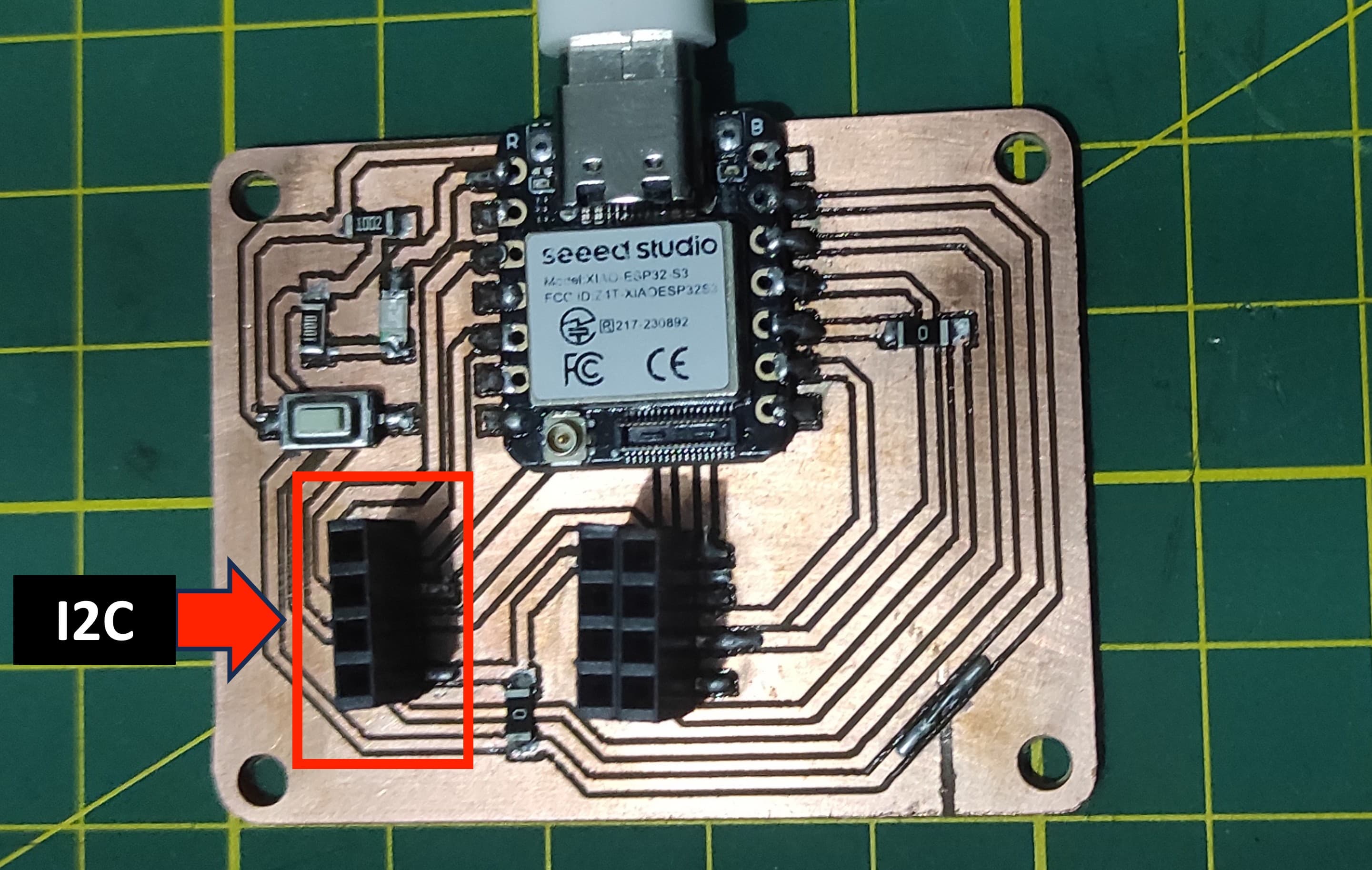
For this assignment, I used the PCB that I designed and manufactured during Week 8: Electronic Production. The board already includes an I2C header and port, which simplifies the integration of I2C devices. Because of this, I was able to connect the OLED display directly to the PCB without needing additional wiring or adapters. This allowed me to quickly test the display and verify that the communication through the I2C interface was working correctly.
3. Learnings
To measure power consumption, I use a multimeter in series with my LED to measure current (mA), or plug a USB power meter between my XIAO and computer to see total system draw. When working with outputs, I remember each GPIO pin is limited to 20mA safe continuous current—my 330Ω resistors ensure this, but if I want more brightness I can use lower values (100Ω for red, 33Ω for blue/green) while staying safe. I always connect LEDs through resistors to prevent damage.
4. Files
Here are the files available for download.