Week02 Computer-Aided Design (CAD)
Week 02 Overview
I started this second week with Global session and takes many more things from there focused on Computer-Aided Design (CAD) as a foundational skill for digital fabrication. The objective was to understand different design representations (raster, vector, 2D, 3D), explore parametric and non-parametric modeling, and evaluate design tools that support modeling, rendering, simulation, and preparation for fabrication. 💕
SSTM
Supply Side Time Management (SSTM)
One of the important habits encouraged in Fab Academy is Supply Side Time Management (SSTM). This concept focuses on managing the supply of your time and effort rather than only reacting to deadlines. Since Fab Academy is intensive and fast-paced, planning work ahead of time is essential to keep up with weekly assignments and documentation.
Key Principles of SSTM
- Plan the week early
- Review the weekly global lecture.
- Identify the required assignments.
-
Estimate the time needed for learning, designing, and documentation.
-
Prepare tools in advance
- Install required software before starting design tasks.
-
Test that the tools work properly.
-
Break tasks into smaller steps
- Software installation
- Learning tutorials
- Practicing small exercises
- Producing assignment results
-
Documenting the process
-
Document while working
- Take screenshots during installation and exercises.
- Save design files.
- Write short notes about challenges and solutions.
Using SSTM helped me prepare my computer and install the required CAD tools early in the week so that I could focus on learning and practicing design workflows.

The week included both a Global Session, which introduced core concepts and expectations, and a Local Session led by Rico, where we installed, explored, and practiced with multiple CAD tools commonly used in Fab Labs.
Downloadign some Software from the open sources, it is better to use them as many software is essential to perfom any tasks here,so subscription will became hardly

Global Session – Computer-Aided Design
Session Focus
The global lecture introduced the following key topics:
- Types of digital models:
Raster (pixel-based images)
Vector (paths and curves)
2D Design
3D Design - Modeling approaches: Solid modeling Surface modeling Parametric vs non-parametric design
- CAD workflows for: Rendering Animation Simulation
- Designing with a final project in mind
- Importance of: Version control File organization Exporting correct formats for fabrication
- Compressing images and videos for web publishing
- Documenting and publishing: Design intent Process Source files on the class website

Weekly Assignment (Global)
- Model a possible final project, with initial ideas
- Use appropriate CAD tools (2D and/or 3D) which will be used throughout the next session and training
- Compress images and videos Xnconvertor (For Images images size, < 150kb), videos(Handbreak learned and sizes here matters so must < 10Mb) we did from 16Mb to 4.7 with this handbreak things.🫢
- Upload: Description of the design Design files (I was given assignement from Rico with Freecad, inkscape and freeacad) Documentation on the class page is must with expected days accomplishment ()
Local Session – CAD Tools Installation & Practice
Instructor: Rico
During the local session, we focused on installing and learning multiple CAD tools to understand their strengths, workflows, and use cases in digital fabrication.

 Image source and credit: to Rico and shared image with me
Installed & Explored Software
1. Autodesk Fusion 360
- Website: https://www.autodesk.com/
- Status: ✅ Installed and practiced
- For my project I prefer this one
- I found it is good for

3D modeling Rendering Animation
Tutorial with Rico was amazing and useful always: we tried to address
About Fusion 360 which is a cloud-based CAD/CAM/CAE software by Autodesk used for: - 2D sketching/3D modeling, - Simulation, rendering, and manufacturing. - It integrates parametric, direct, and surface modeling in a single platform, making it suitable for product design, mechanical parts, and digital fabrication workflows.
 Image source and credit: Provided by Instructor Rico Kanthatham. Used as design reference for 3D modeling.
 - Image source and credit: Provided by Instructor Rico Kanthatham. Used as design reference for 3D modeling.
 Image source and credit: Provided by Instructor Rico Kanthatham. Used as design reference for 3D modeling.
2. Blender
- Website: https://www.blender.org/
- Status: ✅ Installed and practiced
- Use cases: 3D modeling Rendering Animation
- Notes: Powerful open-source tool Best for organic shapes and visualization
3. QCAD
- Website: https://qcad.org/en/
- Status: ✅ Installed
- Use cases: 2D technical drawings DXF files for laser cutting and CNC
- Notes: Lightweight and precise Ideal for fabrication-ready 2D designs
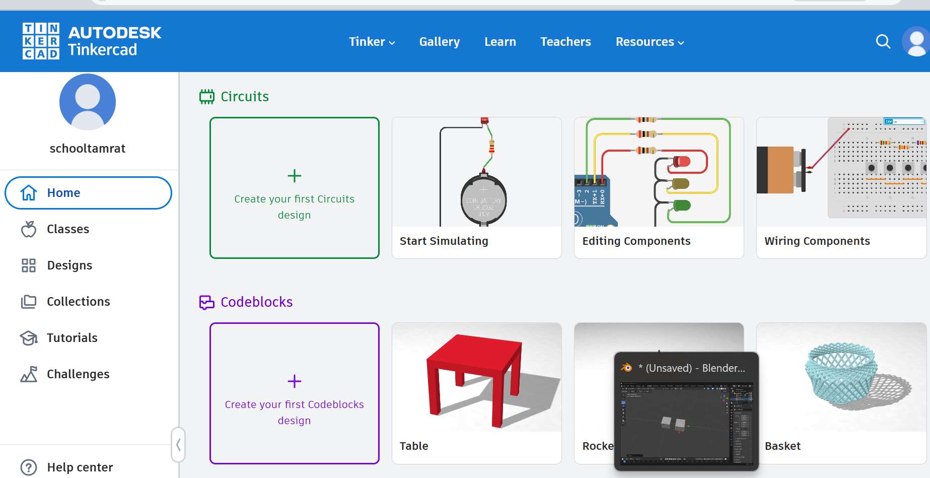
4. TinkerCAD (Online)
- Website: http://www.tinkercad.com/
- Status: ✅ Account created and practiced
- Account:
schooltamrat@gmail.com - Use cases: Beginner-friendly 3D modeling Quick prototyping
- Notes: Browser-based Excellent for rapid concept modeling
5. Rhino
- Website: https://www.rhino3d.com/
- Status: ✅ Already installed and licensed
- License holder: Innobiz-K Ethiopia Incubation Center
- Use cases: NURBS-based 3D modeling Precision industrial and architectural design
- Notes: Very powerful for complex geometry Widely used in fabrication workflows
6. FreeCAD (I explored manythings here)
- Official download: https://www.freecad.org/downloads.php?lang=en
- Status: ✅ Installed
- Notes: Initial website requested subscription Thanks to my instructor Rico 🙏 for providing the correct working link
- Use cases: Parametric 3D modeling Engineering-oriented design
FreeCAD Downloading and Installation
FreeCAD is an open-source parametric 3D CAD software widely used for engineering design and digital fabrication. During the local session, our instructor guided us through installing FreeCAD and testing its basic functionality.
Work on basics with Rico
 Source: Rico at local instruction and tutorial
Steps
Step 1: Access the Official FreeCAD Website
First, I opened the official FreeCAD download page:
https://www.freecad.org/downloads.php?lang=en
This page provides installation files for different operating systems including:
- Windows
- Linux
- macOS
Step 2: Select the Correct Version
Since I am using Windows, I selected the Windows installer.
Recommended version: - Latest stable release
This ensures compatibility with most tutorials and plugins.
Step 3: Download the Installer
- Click the Windows Installer (.exe) file.
- Wait for the download to complete.
- Save the file in the Downloads folder.
Step 4: Run the Installer
After downloading the file:
- Double-click the FreeCAD installer.
- Click Next to begin the installation.
- Accept the license agreement.
- Select the installation folder (default location recommended) by the software developer.
- Click Install.
Step 5: Complete the Installation
Once installation is finished:
- Click Finish.
- Open FreeCAD from the Start Menu.
- Verify that the software launches correctly.
Step 6: Initial Interface Check
When FreeCAD opens, I verified the main interface components:
- Workbench selector
- 3D view window
- Model tree
- Task panel
This confirms that the installation was successful.
Tutorial from youtube was amazing and useful on different basics tool of freeCAD

Tutorial source and credit: https://www.youtube.com/watch?v=cJfbINgyz-k&t=24s
This Video total summarize the above steps for beginners to start to work on the freecad.
Practice Freecad more complex from
https://www.youtube.com/watch?v=Z5HfYcm0HXQ
Starting from the simple polyline and correct with basic tools to advance the freecad 3D modeling SW… as I go I like it.

FreeCAD 3D Modeling Workflow: Multiple Bodies & Fasteners
This guide summarizes the 4-step workflow for creating the assembly demonstrated in the FreeCAD 1.1.0 Dev tutorial.
1. Model the Base (Main Body)
- Sketching: In the PartDesign Workbench, create a new body. Sketch a centered rectangle on the XY plane and add a central circle.
- Extrusion: Use the Pad tool to extrude the sketch into a 3D volume.
- Refinement: Apply Fillets to the outer edges for a rounded finish. Use the Thickness tool on the bottom face to hollow out the part to a set wall thickness.
2. Add Mounting Features
- Cylinders: Sketch two circles on the top face. Use the Pad tool with the Reversed option to extrude them downwards into the hollowed area.
- Threading: Select the circular faces of these new cylinders and use the Hole tool.
- Configuration: Set the hole type to Threaded, select the M4 ISO regular profile, and set the depth to match the mounting requirements.

3. Create the Second Body & Assembly
- Duplication: Copy the first body (
Ctrl+C/Ctrl+V) to create a similar interlocking part. - Modification: Edit the second body by deleting unnecessary operations and adding a Subtractive Pipe or Pocket to create the interlocking slot .
- Alignment: Use the Transform tool to rotate the second body. Utilize the “Move to other object” feature to snap a vertex from the second body directly to a vertex on the first body for perfect alignment.

4. Insert Fasteners
- Workbench: Switch to the Fasteners Workbench (installed via Addon Manager).
- Selection: Generate a screw (e.g., ISO 4762 M4x14) from the toolbar.
- Auto-Placement: Select the screw, then hold
Ctrland select the circular edge of the hole where it belongs. Click the Move Fastener icon to snap the screw into position [00:28:21]. - Final Touch: In the Properties panel, set the Thread property to
Trueif you wish to see the modeled threads on the screw. 
Source Video: FreeCAD 1.1.0 Dev: 3D modeling | PartDesign multiple body
7. Google SketchUp
- Website: http://sketchup.google.com/
- Status: ✅ Already installed (SketchUp 2024)
- Use cases: Fast conceptual 3D modeling Architecture and layout design
- Notes: Easy to learn Less precise for fabrication without plugins
8. OpenSCAD
- Website: http://www.openscad.org/
- Status: ✅ Installed
- Use cases:
- Script-based parametric modeling
- Notes:
- Code-driven design
- Excellent for repeatable and adjustable parts

9. Inkscape
I learn new skill in inkscape, and is a free, open-source vector graphics design software used for creating and editing scalable graphics such as logos, icons, diagrams, technical drawings, and illustrations. It works primarily with the SVG (Scalable Vector Graphics) format, which is ideal for digital fabrication and precision design.
Uses
- 2D vector drawing and illustration
- Preparing designs for laser cutting, vinyl cutting, and CNC machines
- Creating logos, posters, and technical diagrams
- Editing and converting raster images into vector format (tracing)
- Designing layouts for fabrication workflows
Current Version
The current stable version of Inkscape I installed is Inkscape 1.4.3 (0d15f75, 2025-12-25), offering improved performance, a modernized interface, enhanced path tools, better text handling, and improved SVG compatibility as i see. It will be usefull here in my fabacademy to create precise vector files required for machines like laser cutters and plotters. Its accuracy, support for layers, node editing, and export options make it a powerful tool for preparing fabrication-ready designs.
Tutorial from youtube was amazing and useful on different basics tool Inkscape
Inkscape Quick Start Guide: 4-Step Summary
This guide outlines the essential workflow for beginners using Inkscape, based on the Complete Starter Guide.
1. Document Setup & Interface
- Launch & Templates: Use the Welcome Dialog to choose a workspace theme (Light/Dark) and document template (Print, Social Media, or Video) [00:02:11].
- Manual Properties: Access File > Document Properties to set specific units (pixels for web, inches for print), page size, and orientation [00:07:22].
- Layout Navigation: Hold the Mouse Wheel to pan around the canvas and hold Ctrl + Mouse Wheel to zoom in and out efficiently [00:17:02].
2. Creating & Manipulating Shapes
- Basic Shapes: Use the Rectangle, Circle, or Stars tools to draw objects. Hold Ctrl while drawing to create perfect squares or circles [00:18:54].
- Transformation: Click an object once to show Scaling handles; click a second time to show Rotation handles [00:19:57].
- Nodes & Paths: Convert a shape to a path using Path > Object to Path to reveal Nodes. Use the Node Tool to drag these points and reshape the object [00:25:27].
3. Path Operations & Alignment
- Boolean Operations: Create complex shapes by selecting two objects and using Path > Union (to merge) or Path > Difference (to subtract) [00:30:32].
- Alignment: Open the Align and Distribute menu (
Object > Align and Distribute) to perfectly center objects relative to each other or the page [00:33:07]. - Shape Builder: For advanced designs, use the Shape Builder Tool to click and drag through overlapping segments to add or subtract specific areas [00:42:21].
4. Styling, Saving & Exporting
- Fill & Stroke: Use the Fill and Stroke menu to set the interior color (Fill) and outline thickness/color (Stroke). Hold Shift while clicking a color to set the stroke color [00:36:26].
- Saving Projects: Use File > Save As and choose Inkscape SVG to keep your layers and paths editable for future work [00:44:13].
- Exporting Images: To create a shareable picture (PNG/JPEG), select your object, go to File > Export, and choose the Selection tab to save only the highlighted artwork [00:45:12].

Source Video: Inkscape Tutorial: Complete Starter Guide for New Users
My prefernces
I have to learn more about all and decide further what apps to use where and when:
So far this week I did:
- Understand differences between raster, vector, 2D, and 3D models
Raster vs Vector Images (My Understanding)
During this week I learned the difference between raster and vector images and when each type is useful in digital fabrication.
Raster Images
Raster images are made of pixels (tiny colored squares) arranged in a grid. Each pixel stores color information, which creates the final picture.
Key characteristics: - Resolution dependent - Quality decreases when scaled larger - Best for complex images with many colors
Common raster formats: - JPG - PNG - GIF
Example use: - Photographs - Detailed textures - Website images
However, raster images are not ideal for fabrication machines like laser cutters because machines cannot easily follow pixel data as toolpaths.
Vector Images
Vector images are made using mathematical paths, lines, curves, and shapes instead of pixels.
Key characteristics: - Resolution independent - Can be scaled infinitely without losing quality - Shapes are defined by coordinates and equations
Common vector formats: - SVG - DXF - AI - EPS
Example use: - Laser cutting - Vinyl cutting - CNC toolpaths - Logo design
Machines prefer vector files because they can follow the exact path of lines and curves.
My Practical Understanding
From this week’s learning, I understood that:
- Raster images are better for viewing and photography
- Vector images are better for fabrication and machine cutting
For example: - If I want to print a photo → I use PNG or JPG - If I want to cut a design using a laser cutter or vinyl cutter → I use SVG or DXF
- Compare parametric and non-parametric design approaches
- Install and test multiple CAD tools
- Identify which tools are best suited for: Concept design Precision fabrication Parametric modeling
- Begin thinking about CAD workflows aligned with my final project
- I stacked with FUSION 360 for now on 3D things, but I see Blender do more on the complex art things too from my instructor. —>
Compressing Images and Videos
One important requirement for Fab Academy documentation is to compress images and videos before uploading them to the class website. Large media files can slow down the website and increase the size of the Git repository. Therefore, reducing file sizes while maintaining acceptable quality is an important part of the documentation workflow.
For this assignment, I used the following tools:
- XnConvert for compressing images
- HandBrake for compressing videos
Image Compression Using XnConvert
XnConvert is a powerful and free batch image converter that allows resizing, compressing, and converting multiple images at once.
Downloading XnConvert
To download the software:
-
Open the official website
https://www.xnview.com/en/xnconvert/ -
Select your operating system
- Windows
- macOS
-
Linux
-
Download the installer file.
-
Run the installer and follow the installation instructions.
Steps to Compress Images with XnConvert
Step 1 – Open XnConvert
After installation:
- Launch XnConvert.
- The interface will show three main tabs:
- Input
- Actions
- Output
Step 2 – Add Images
- Click Add Files.
- Select the images you want to compress.
- The selected images will appear in the input list.
This allows multiple images to be processed at once.
Step 3 – Add Compression or Resize Action
- Go to the Actions tab.
- Click Add Action.
- Select Image → Resize.
Example settings: - Resize to 1920 px width or smaller - Maintain aspect ratio
Resizing reduces image dimensions and file size.
Step 4 – Configure Output Settings
- Open the Output tab.
- Choose the file format (JPG or PNG).
- Adjust the quality level.
Example: - JPG quality: 70–80%
This keeps good visual quality while reducing file size.
Step 5 – Convert the Images
- Choose an output folder.
- Click Convert.
XnConvert will create compressed versions of all selected images.
Step 6 – Use Compressed Images in Documentation
After compression:
- Replace the original large images with the compressed versions.
- Insert them into the Markdown documentation.
XnConvert starting and working on onscreen steps as above

Video Compression Using HandBrake
HandBrake is a free and open-source tool used to compress and convert video files. It helps reduce video file size while maintaining reasonable quality.
Downloading HandBrake
To download the software:
-
Visit the official website
https://handbrake.fr/ -
Click Download HandBrake.
-
Select the version for your operating system:
- Windows
- macOS
-
Linux
-
Download and install the software.
Steps to Compress Videos Using HandBrake
Step 1 – Open HandBrake
After installation:
- Launch HandBrake.
- The main window will prompt you to open a video file.
Step 2 – Import the Video File
- Click Open Source.
- Select the video file you want to compress.
HandBrake will scan the video and load it into the interface.
Step 3 – Select a Compression Preset
HandBrake provides preset settings for common video formats.
Example preset: - Fast 1080p30
This preset balances quality and file size.
Step 4 – Adjust Video Settings (Optional)
If further compression is needed:
- Go to the Video tab.
- Adjust:
- Video codec (H.264 recommended)
- Quality slider
Lower quality values produce smaller files.
Step 5 – Choose the Output Location
- Select where the compressed video will be saved.
- Rename the file if necessary.
Step 6 – Start Compression
- Click Start Encode.
- HandBrake will begin compressing the video.
Once completed, the compressed video file will be significantly smaller than the original.
Step 7 – Use the Compressed Video for Documentation
The compressed video can now be:
- uploaded to the project repository
- embedded in the Fab Academy documentation page

What I Learned
From this process, I learned that:
- Compressing media files is essential for efficient documentation.
- Image compression reduces repository size and speeds up website loading.
- Video compression makes it easier to upload and share demonstrations.
- Tools like XnConvert and HandBrake are effective for preparing media files for Fab Academy documentation.
✅ This will directly answer your instructor’s comment because it shows:
the exact tools used
download links
clear step-by-step procedure
image placeholders after explanation
If you want, I can also show you a very common Fab Academy trick students use to reduce images from 8 MB → 200 KB automatically, which instructors really like in documentation.
My Next Steps are:
- Select the most appropriate CAD tool for my final project (Might be the Car side mirror theft alarm) and learn other tools, “pros and cons”
- Develop a preliminary 2D and/or 3D model
- Optimize files for fabrication
- Continue improving documentation quality and clarity with weeks SSTM alignment, Saturday > 40% 🤦♀️🏃♀️
My Final Project Idea Started with Fusion 360:
I selected the most appropriate CAD tool for my final project is Fusion 360 but learn all in the progress and use the best out of them.
Look @ my FP to fusion 360
This project focuses on the design and development of an automobile side mirror as part of the final project work. The initial 3D modeling has started in Fusion 360 using parametric design methods to define the core geometry and structure.
This is the first stage of the design process, and the model will be continuously improved, refined, and expanded in future work using additional design tools and simulations with my learn and unlearning process through Fabacademy course.
Starting my FP with Fusion 360 modeling basic FP ideas

Cars renders final project ideas and familiarize the tools in the platform

Cars renders in more good quality final project ideas for a better images and descriptions

Challanges
To many times out of zoom connection from my instructor (Rico), sorry Ric 🙌. Order from my higher official at my FabTime.


Refernce
- Fabacademy resources and tutorials https://fabacademy.org/2026/classes/computer_design/index.html Ricos resources on notion page: https://www.notion.so/week-2-2D-3D-Design-2f69bb27ac9880ea89c2efff5cba485d
- Learn from global sesion week02
- Downloading from the fabacademy.or and instructors provided links and info
- Lolal instructor, (provided the updated links) and instruction, deep dive to how to use those apps with Rico
- chatGPT, with prompt says “provide me with blender app useful shortcutts”
