// WEEK 02
Computer-Aided Design (CAD)
1. Introduction
This week’s assignment focused on Computer-Aided Design (CAD). The objective was to model a possible final project using 2D and 3D software, document the modeling process, compress images and videos, and upload the original design files.
2D Modeling Process
Inkscape
I used Inkscape as my 2D design software. Inkscape works as a vector graphics editor, which means it creates designs using mathematical paths instead of pixels. Unlike raster images that are made of tiny squares (pixels) and lose quality when resized, vector graphics remain sharp and accurate at any size because they are defined by equations and curves.
I used Inkscape to convert a raster image into a vector format. This process is important because vector files are scalable and suitable for digital fabrication processes such as laser cutting and CNC machining.
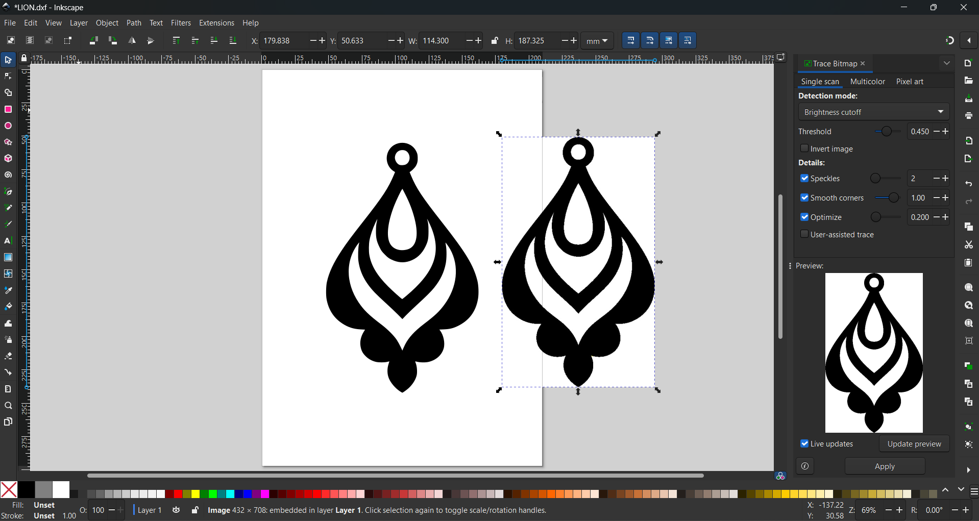
Video: Converting Raster to Vector (ink orign)
2D in Aspire
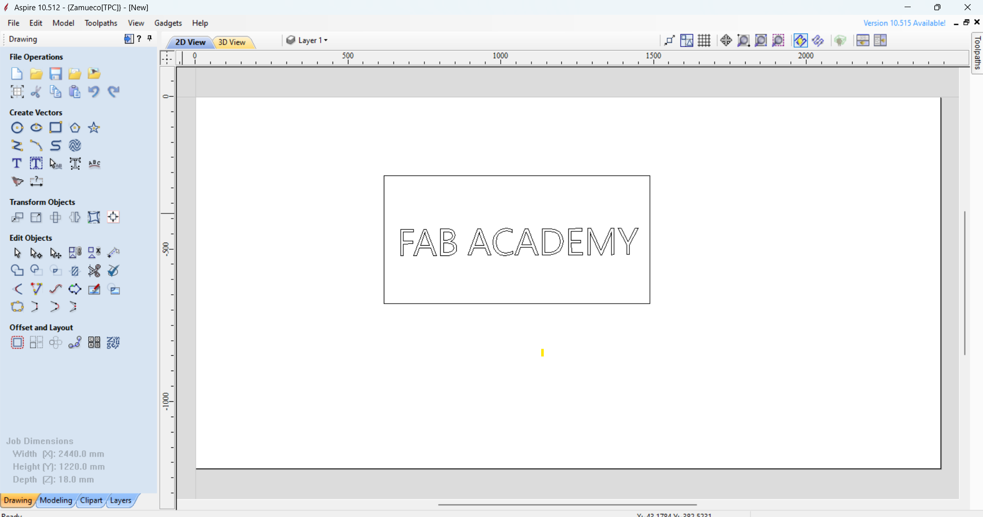
In Aspire, 2D design is the starting point for everything you create, acting as the blueprint for 3D carvings. You use tools to draw shapes like lines, circles, rectangles, curves, and text, which are called vectors. These vectors define the paths that the CNC machine will follow when cutting or carving materials.
3D Modeling Process
3D Modeling Concepts
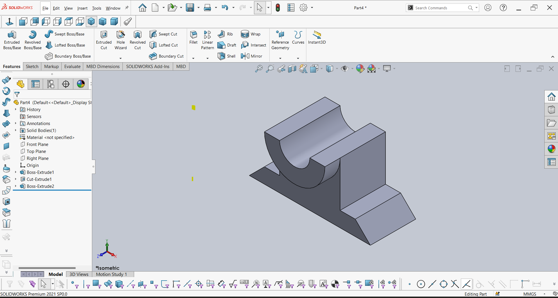
3D modeling means creating a digital representation of a real object in three dimensions: length, width, and height. In SolidWorks, you don’t just draw shapes—you can simulate how parts will look and even function before making them in real life.
SolidWorks Workflow
In SolidWorks, 2D sketches are the foundation of all 3D models. You start by drawing shapes such as lines, circles, rectangles, or curves on a plane, and then use features like extrude, revolve, or loft to turn these flat sketches into 3D parts.
SolidWorks Process Video
Tools & Technologies
- Inkscape (Vector Editing)
- Aspire (CNC Preparation)
- SolidWorks (Parametric 3D CAD)
Design Files
Download the original design files generated during this week's CAD exploration.