// Week 14
Interface and Application Programming
Introduction
This documentation outlines the Interface and Application Programming phase for my project, which uses an Arduino Mega microcontroller and a DHT22 sensor to measure temperature and humidity.
The system reads environmental data from the DHT22, transmits it to the Serial Monitor, and sends it via serial communication to a custom dynamic dashboard developed using the Processing IDE.
Objectives
Group Assignment
Compare different interface and application programming tools, exploring their workflows and ideal use cases.
Individual Assignment
- Read temperature and humidity data from a DHT22 sensor using an Arduino Mega.
- Output continuous telemetry onto the Arduino Serial Monitor.
- Develop an interactive graphical dashboard in Processing IDE to parse and visualize serial data in real time.
System Concept
Hardware & System Overview
- Processing Unit: Arduino Mega Microcontroller
- Input System: DHT22 Temperature & Humidity Sensor
- Output System: Serial Monitor and Processing IDE Dashboard
- Sensor System: Ambient Air Temperature and Relative Humidity
- Power & Interface: USB Communication and Power Cable
Before landing on this finalized setup, I attempted multiple hardware configurations with different microcontrollers and display interfaces. The journey involved extensive troubleshooting across several custom boards.
Development Process & Hardware Iterations
Iteration 1: Custom Seeed XIAO RP2040 Board & MQ135 Sensor
My initial attempt utilized a custom PCB designed in previous weeks featuring a Seeed XIAO RP2040 microcontroller, an MQ135 gas sensor, and a 16x2 I2C LCD screen. The goal was to acquire air quality readings and broadcast them over a web interface.
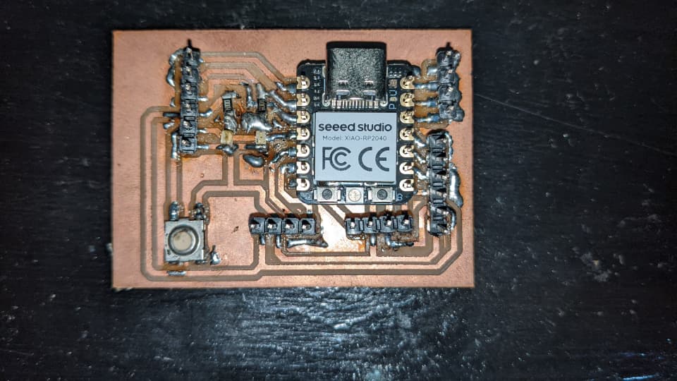
Custom designed PCB populated with Seeed XIAO RP2040
Hardware Setup & Wiring
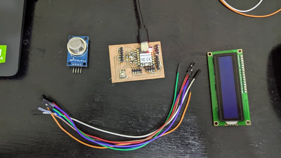
Components staged for testing
| Device | Pin | Connection on RP2040 |
|---|---|---|
| MQ135 Gas Sensor | VCC | 3.3V |
| GND | GND | |
| AO | A0 | |
| 16x2 I2C LCD | VCC | 5V / 3.3V |
| GND | GND | |
| SDA | D4 | |
| SCL | D5 |
RP2040 Sensor Acquisition Code
I utilized the LiquidCrystal_I2C library (installed via Sketch > Include Library > Manage Libraries) to print outputs to the LCD screen.
const int mq135Pin = A0;

void setup() {
  Serial.begin(9600);
}

void loop() {
  int sensorValue = analogRead(mq135Pin);

  // Convert to voltage (RP2040 ADC is 12-bit: 0–4095)
  float voltage = sensorValue * (3.3 / 4095.0);

  Serial.print("Gas Level: ");
  Serial.print(sensorValue);
  Serial.print(" | Voltage: ");
  Serial.println(voltage);

  delay(1000);
}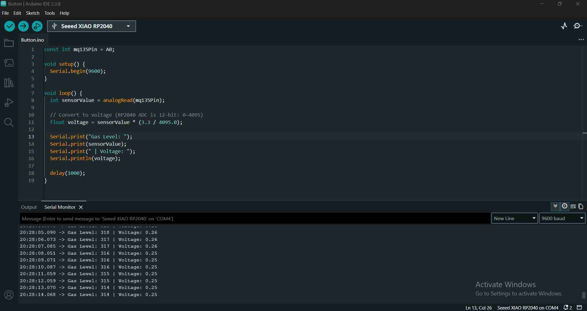
Successful initial serial readout from MQ135 sensor
RP2040 Bootloader Failure
Shortly into testing, the RP2040 suddenly stopped accepting firmware flashes. The IDE consistently returned flashing errors despite putting the board into BOOT mode via the reset/boot buttons.
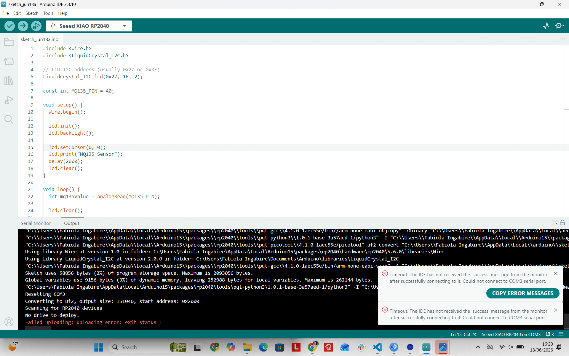
Persistent flash upload error encountered with the RP2040 board
Iteration 2: ESP32-S3 with TFT GC9A01A & DHT22
Following the RP2040 issue, I migrated to an ESP32-S3 connected to a round 1.28-inch GC9A01A SPI TFT display and a DHT22 sensor.
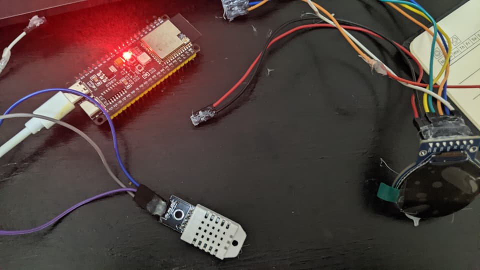
ESP32-S3 microcontroller wired with TFT circular display
Wiring Topology
| Device | Pin | ESP32-S3 Pin |
|---|---|---|
| TFT OLED (GC9A01A) | VCC | 3.3V |
| GND | GND | |
| CS | GPIO 10 | |
| DC | GPIO 9 | |
| RST | GPIO 8 | |
| DHT22 Sensor | VCC | 3.3V / 5V |
| GND | GND | |
| DATA | GPIO 20 |
Library Installation & Display Test
I installed both Adafruit_GFX and Adafruit_GC9A01A libraries via the Arduino Library Manager to drive graphics over SPI.
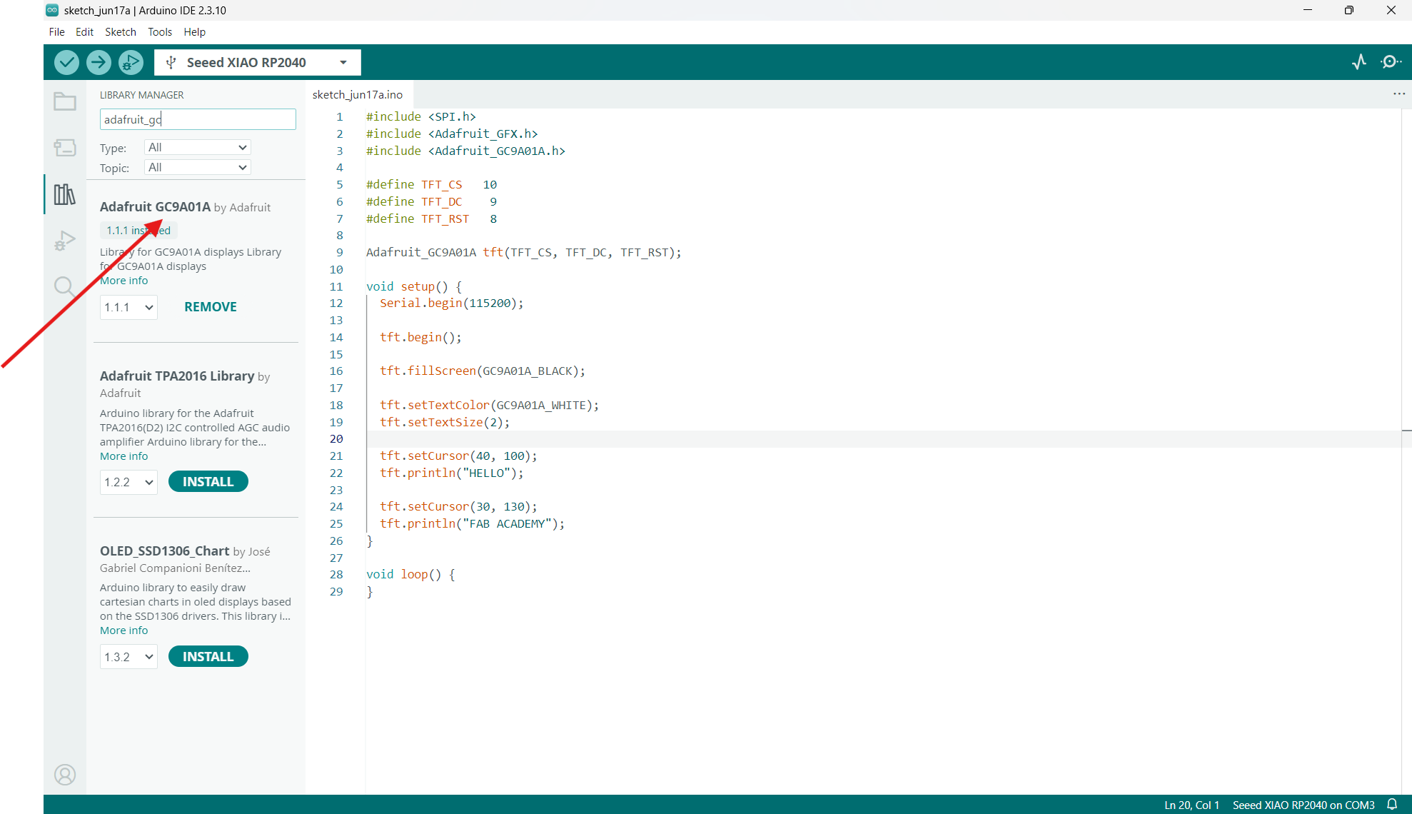
Installing Adafruit GFX core library
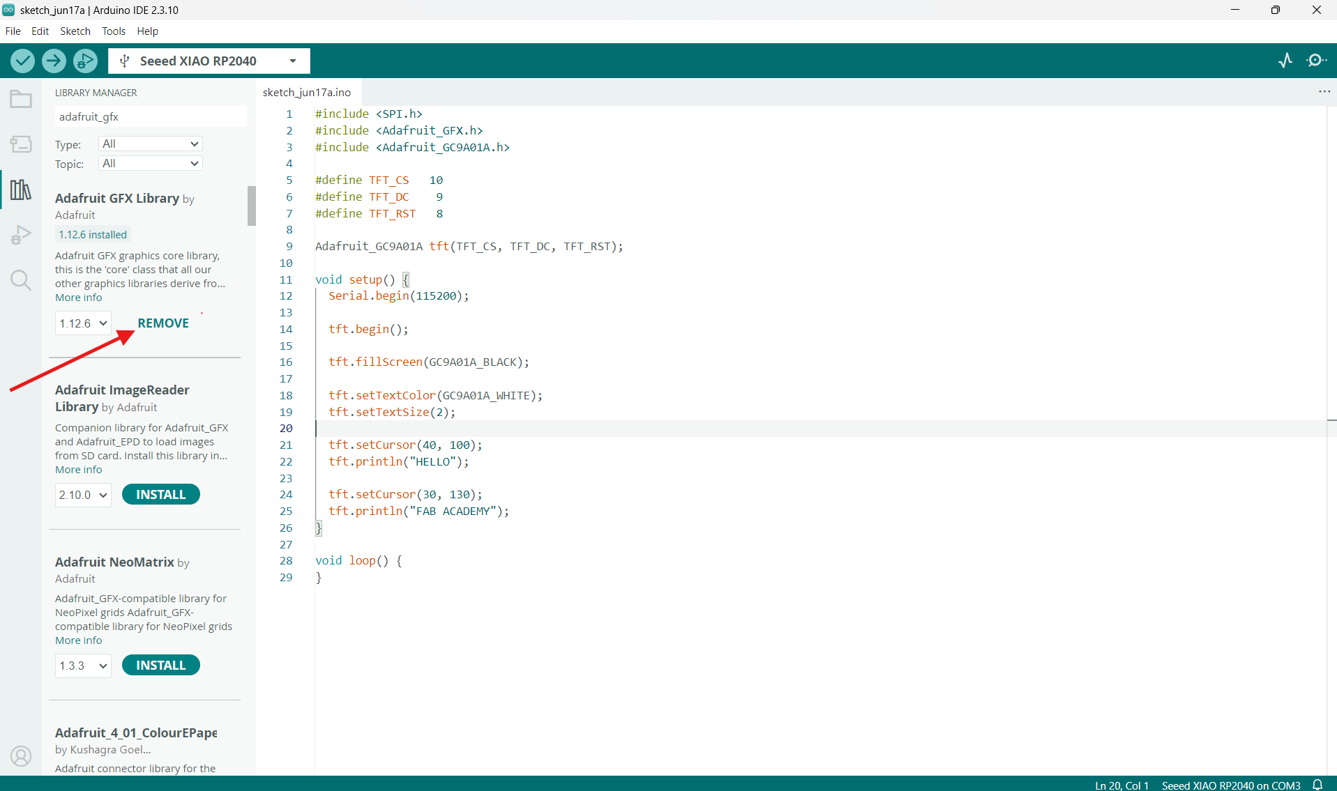
Installing Adafruit GC9A01A driver library
#include <SPI.h>
#include <Adafruit_GFX.h>
#include <Adafruit_GC9A01A.h>

#define TFT_CS   10
#define TFT_DC    9
#define TFT_RST   8

Adafruit_GC9A01A tft(TFT_CS, TFT_DC, TFT_RST);

void setup() {
  Serial.begin(115200);

  tft.begin();
  tft.fillScreen(GC9A01A_BLACK);
  tft.setTextColor(GC9A01A_WHITE);
  tft.setTextSize(2);

  tft.setCursor(40, 100);
  tft.println("HELLO");

  tft.setCursor(30, 130);
  tft.println("FAB ACADEMY");
}

void loop() {
}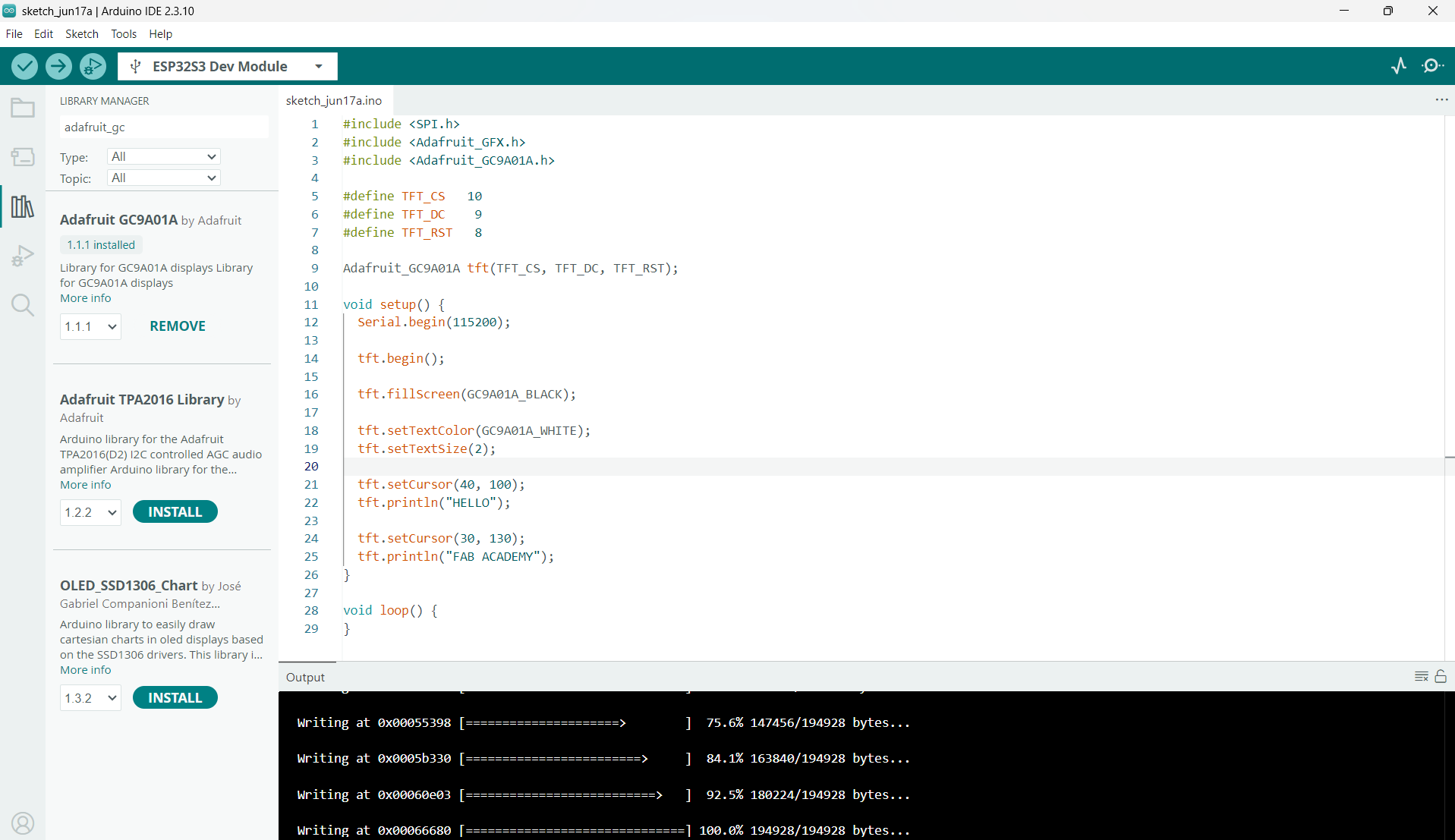
Compiling screen test code
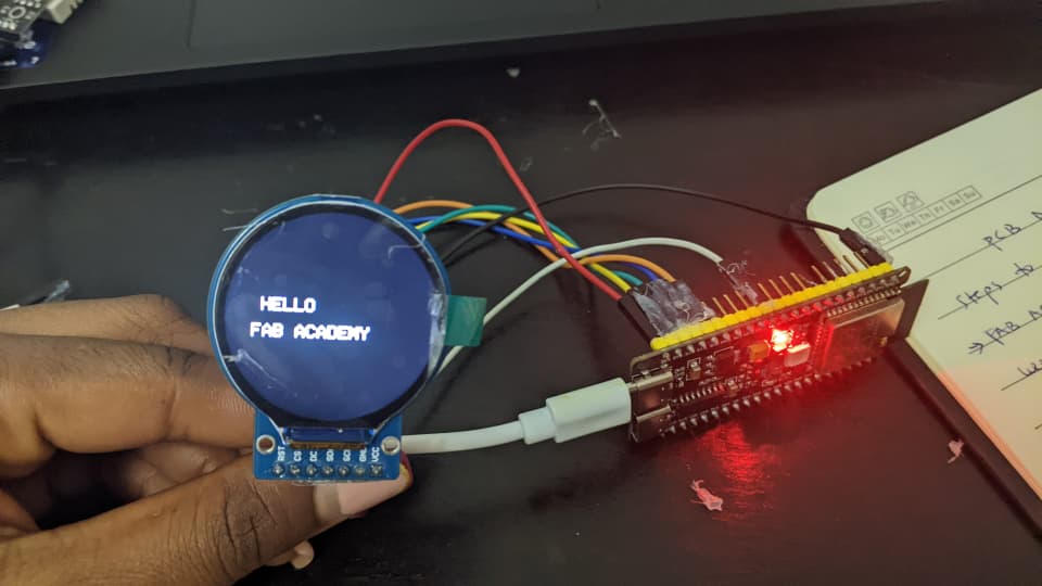
Verification of functional SPI TFT display
Integrating DHT22 with TFT Output
#include <SPI.h>
#include <Adafruit_GFX.h>
#include <Adafruit_GC9A01A.h>
#include <DHT.h>

#define TFT_CS   10
#define TFT_DC    9
#define TFT_RST   8

#define DHTPIN   20
#define DHTTYPE  DHT22

Adafruit_GC9A01A tft(TFT_CS, TFT_DC, TFT_RST);
DHT dht(DHTPIN, DHTTYPE);

void setup() {
  Serial.begin(115200);
  dht.begin();

  tft.begin();
  tft.fillScreen(GC9A01A_BLACK);
  tft.setTextColor(GC9A01A_WHITE);
  tft.setTextSize(2);

  tft.setCursor(40, 100);
  tft.println("AURA");
  delay(2000);
}

void loop() {
  float temp = dht.readTemperature();
  float hum  = dht.readHumidity();

  if (isnan(temp) || isnan(hum)) {
    Serial.println("DHT22 read failed");
    tft.fillScreen(GC9A01A_BLACK);
    tft.setCursor(40, 120);
    tft.setTextColor(GC9A01A_RED);
    tft.setTextSize(2);
    tft.println("DHT ERROR");
    delay(2000);
    return;
  }

  Serial.print("Temp: ");
  Serial.print(temp);
  Serial.print(" C  Humidity: ");
  Serial.print(hum);
  Serial.println(" %");

  tft.fillScreen(GC9A01A_BLACK);
  tft.setTextColor(GC9A01A_CYAN);
  tft.setTextSize(2);
  tft.setCursor(55, 40);
  tft.println("AURA");

  tft.setTextColor(GC9A01A_WHITE);
  tft.setCursor(25, 110);
  tft.print(temp, 1);
  tft.println(" C");

  tft.setCursor(25, 150);
  tft.print(hum, 1);
  tft.println(" %");

  delay(2000);
}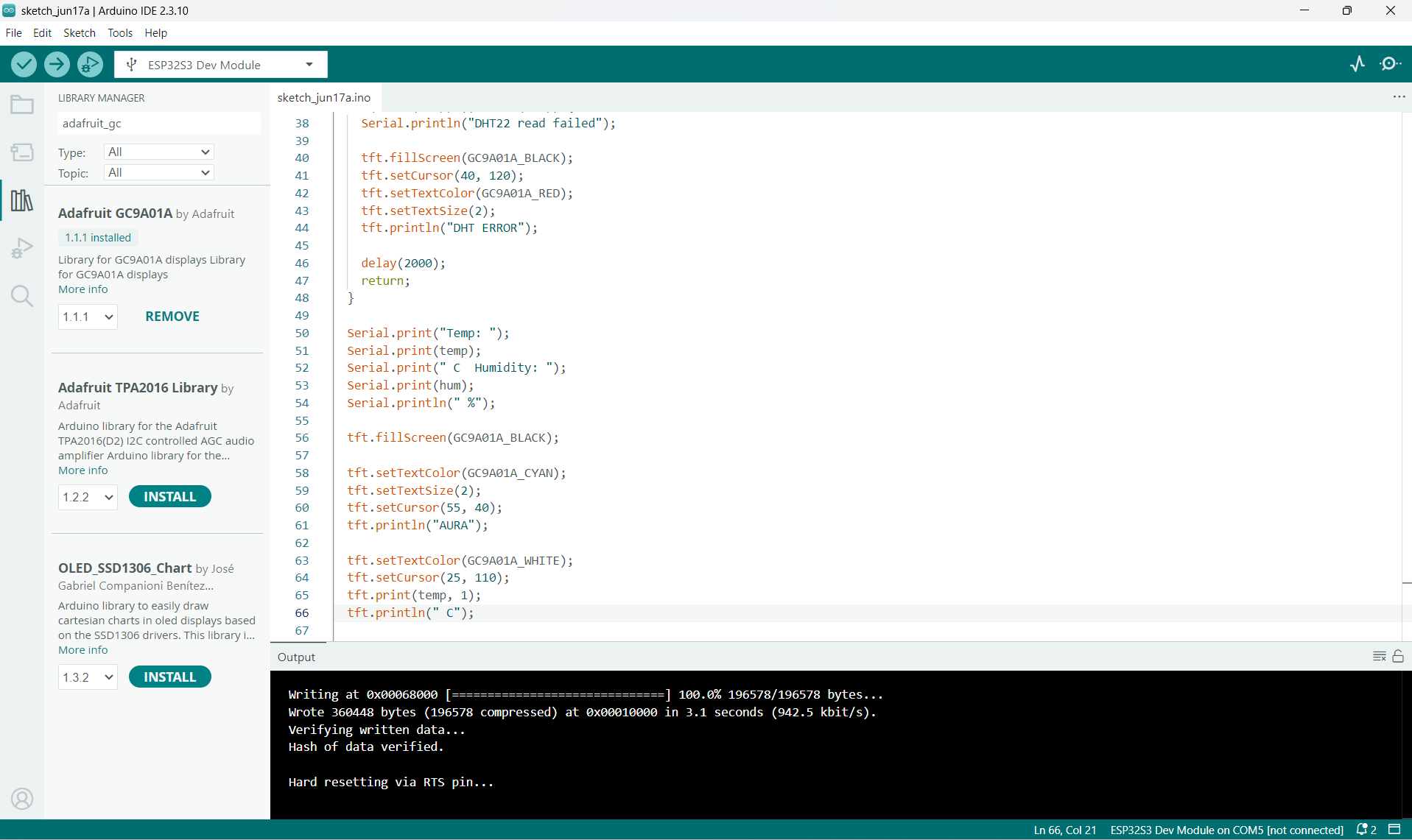
Compilation of full system sketch
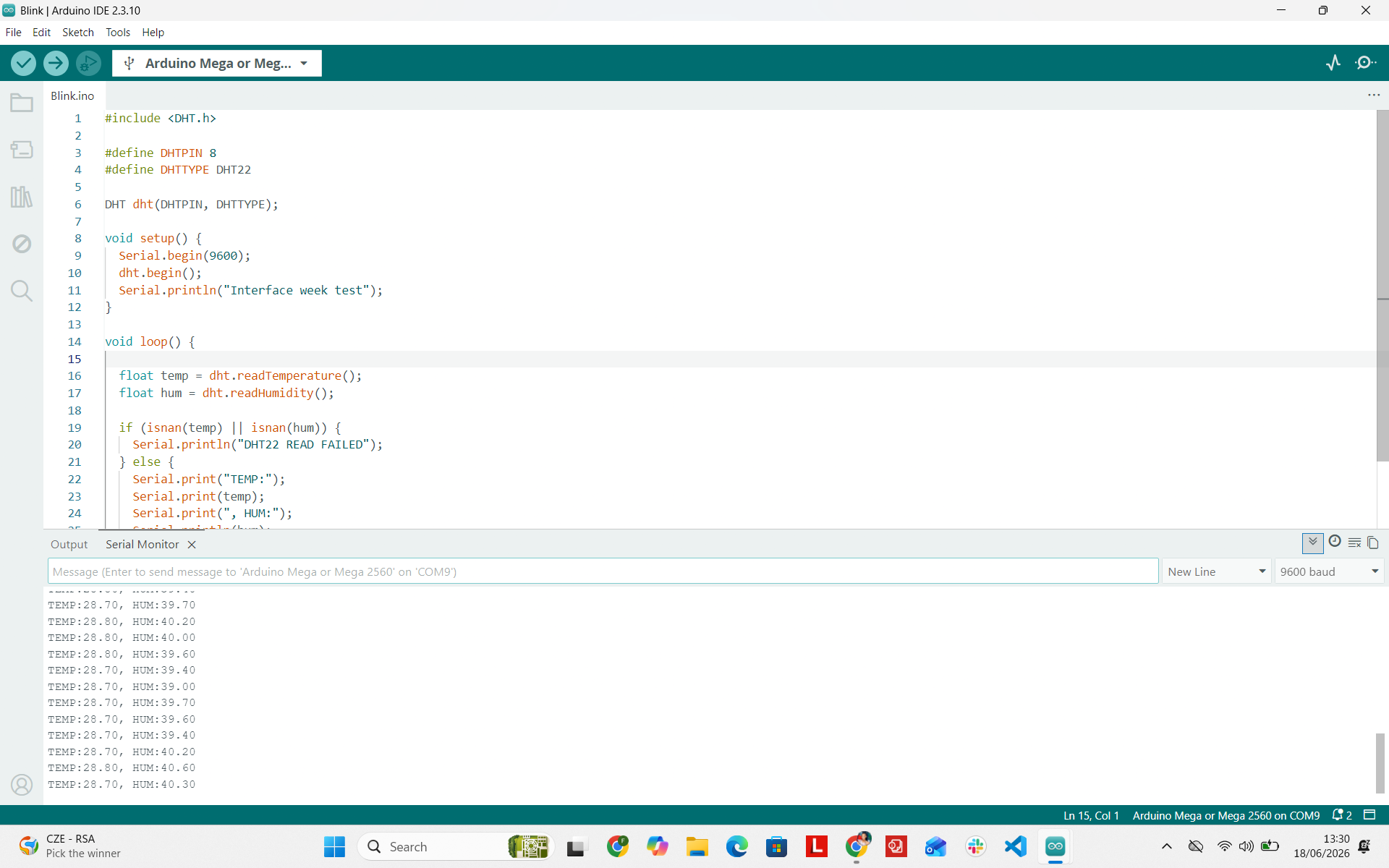
Serial telemetry verified on Arduino IDE console
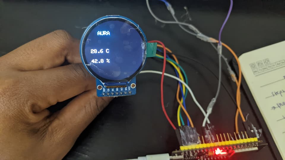
Live sensor readings displayed on circular TFT screen
ESP32-S3 Flash Failure & Disconnections
While finalizing the user interface, the ESP32-S3 began disconnecting randomly from the host computer and consistently threw communication timeout errors during flashing.
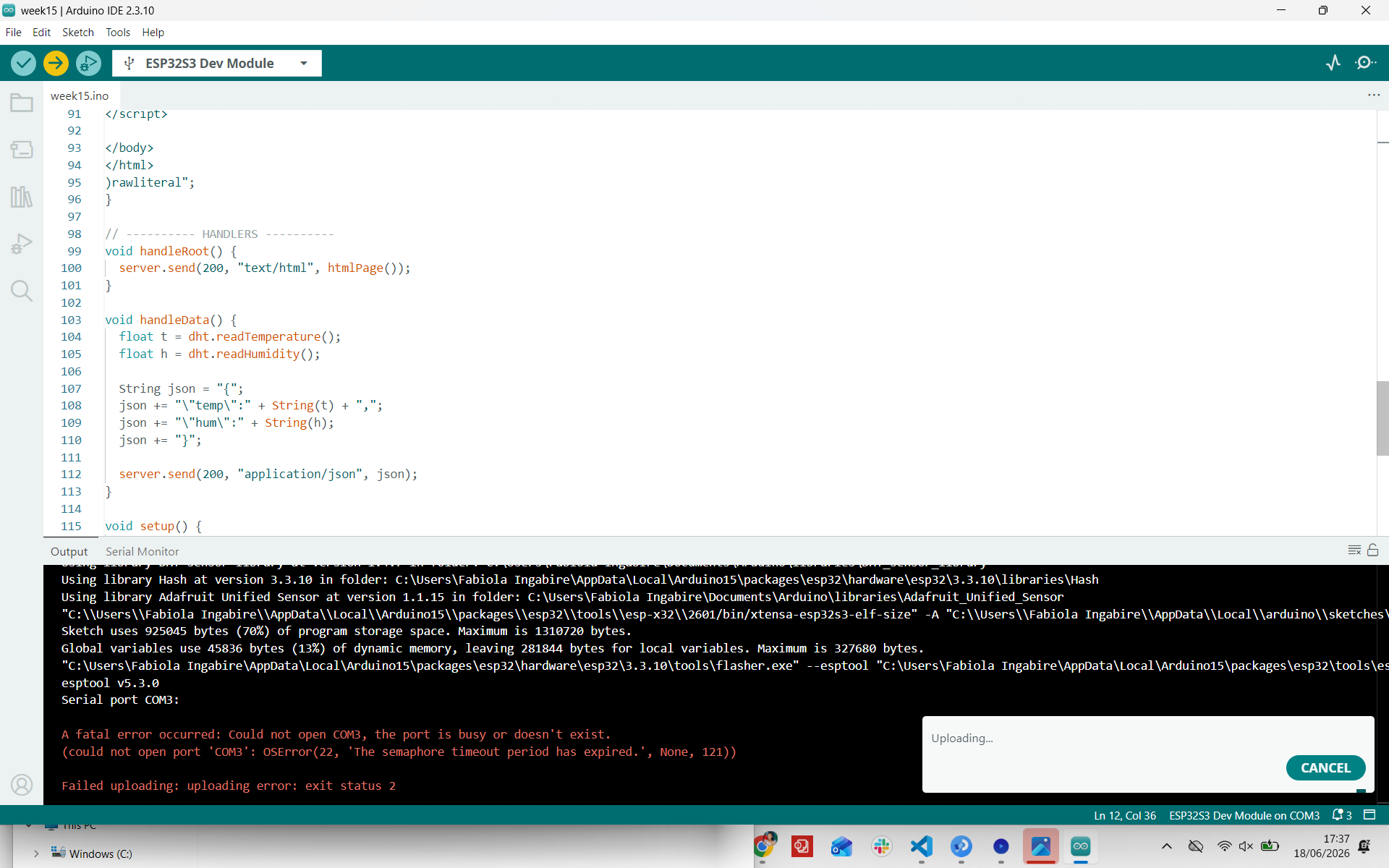
Failed upload error log on ESP32-S3
Iteration 3 (Final Implementation): Arduino Mega 2560 & Processing IDE
To maintain project progress without being blocked by hardware failures, I transitioned to a reliable **Arduino Mega 2560** connected to the DHT22 sensor, transmitting formatted serial packets to a desktop interface designed in **Processing 4.5.2**.
Processing IDE Installation
I downloaded Processing 4.5.2 from the official portal (processing.org/download). Processing serves as an execution framework to bridge physical microcontrollers with custom desktop GUIs.
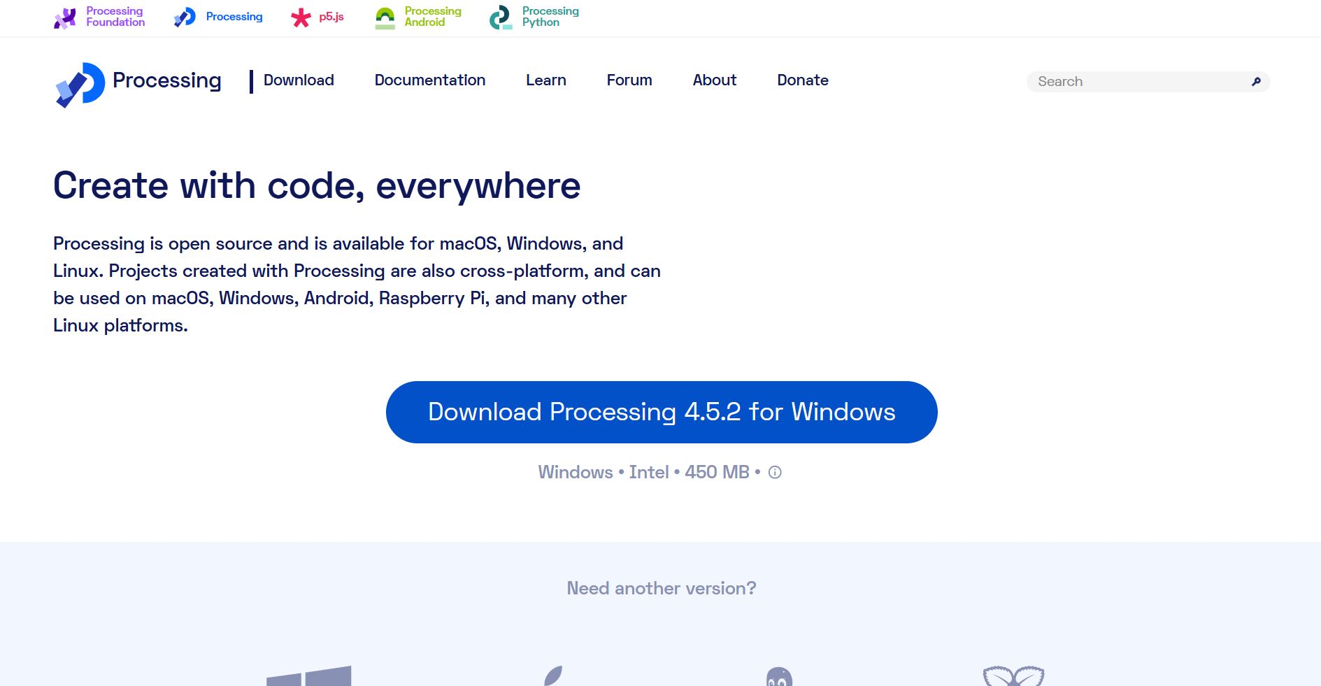
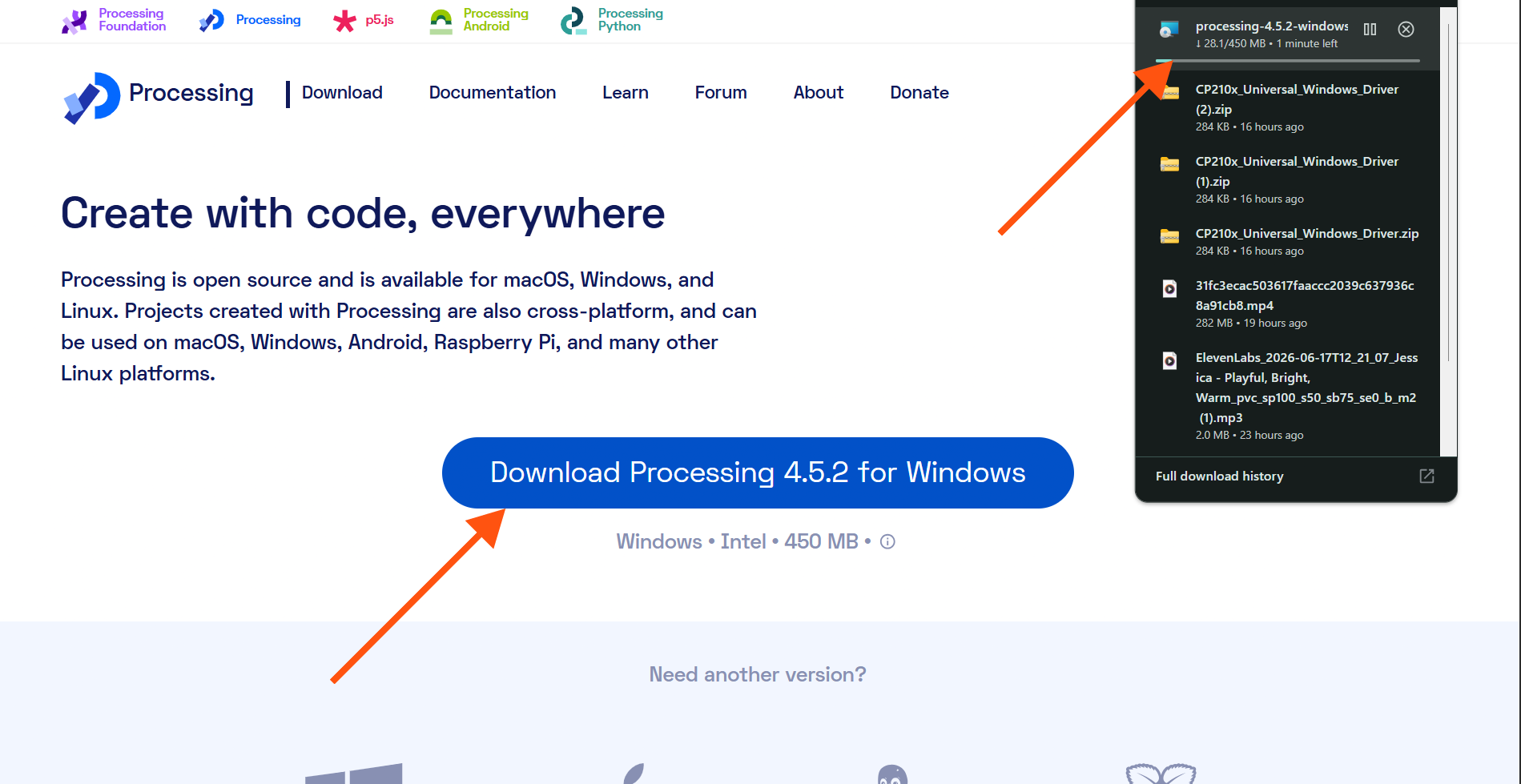
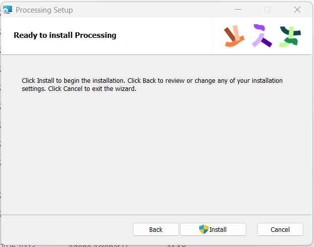
Processing 4.5.2 installation and workspace launch
Arduino Mega Hardware Setup
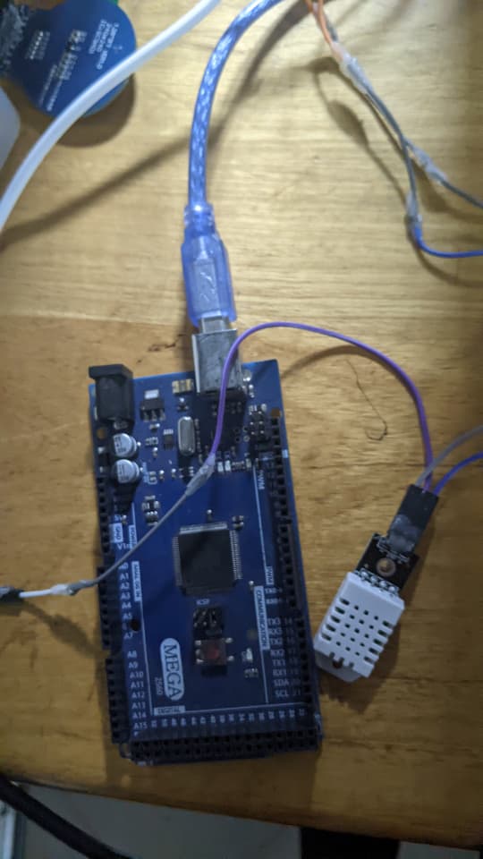
Arduino Mega 2560 interfaced with DHT22 module
| Device | Pin | Arduino Mega Connection |
|---|---|---|
| DHT22 Sensor | VCC | 5V / 3.3V |
| GND | GND | |
| DATA / OUT | Digital Pin 8 |
Arduino Mega Firmware Code
#include <DHT.h>

#define DHTPIN 8
#define DHTTYPE DHT22

DHT dht(DHTPIN, DHTTYPE);

void setup() {
  Serial.begin(9600);
  dht.begin();
}

void loop() {
  float temp = dht.readTemperature();
  float hum  = dht.readHumidity();

  if (!isnan(temp) && !isnan(hum)) {
    Serial.print(temp);
    Serial.print(",");
    Serial.println(hum);
  }

  delay(2000);
}
Processing Dashboard GUI Application Code
import processing.serial.*;

Serial myPort;

float temp = 0;
float hum = 0;

void setup() {
  size(800, 600);
  println(Serial.list());

  // Match COM port used by Arduino Mega
  myPort = new Serial(this, "COM3", 9600);
  myPort.bufferUntil('\n');

  textAlign(CENTER, CENTER);
}

void draw() {
  background(15, 23, 42);

  fill(56, 189, 248);
  textSize(36);
  text("SMART ROOM MONITOR", width/2, 60);

  fill(255);
  textSize(28);
  text("Temperature", width/2, 180);

  textSize(60);
  text(nf(temp, 0, 1) + " °C", width/2, 250);

  textSize(28);
  text("Humidity", width/2, 360);

  textSize(60);
  text(nf(hum, 0, 1) + " %", width/2, 430);

  textSize(32);
  if(temp < 18) {
    fill(0, 150, 255);
    text("COLD", width/2, 530);
  } else if(temp > 28) {
    fill(255, 80, 80);
    text("HOT", width/2, 530);
  } else {
    fill(0, 255, 100);
    text("COMFORTABLE", width/2, 530);
  }
}

void serialEvent(Serial myPort) {
  String data = trim(myPort.readStringUntil('\n'));

  if(data != null) {
    String[] values = split(data, ',');
    if(values.length == 2) {
      temp = float(values[0]);
      hum = float(values[1]);
    }
  }
}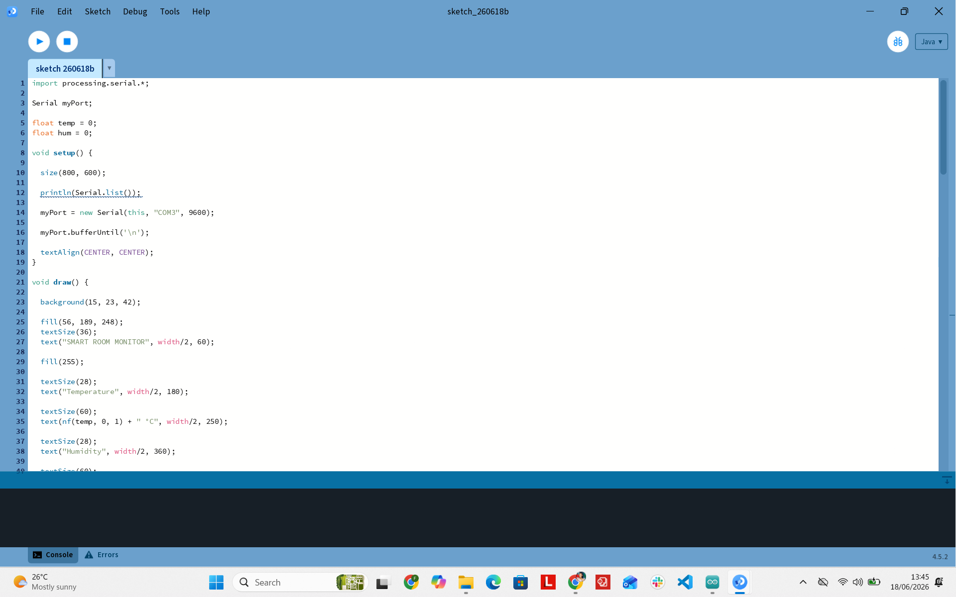
Processing script prepared and ready to compile
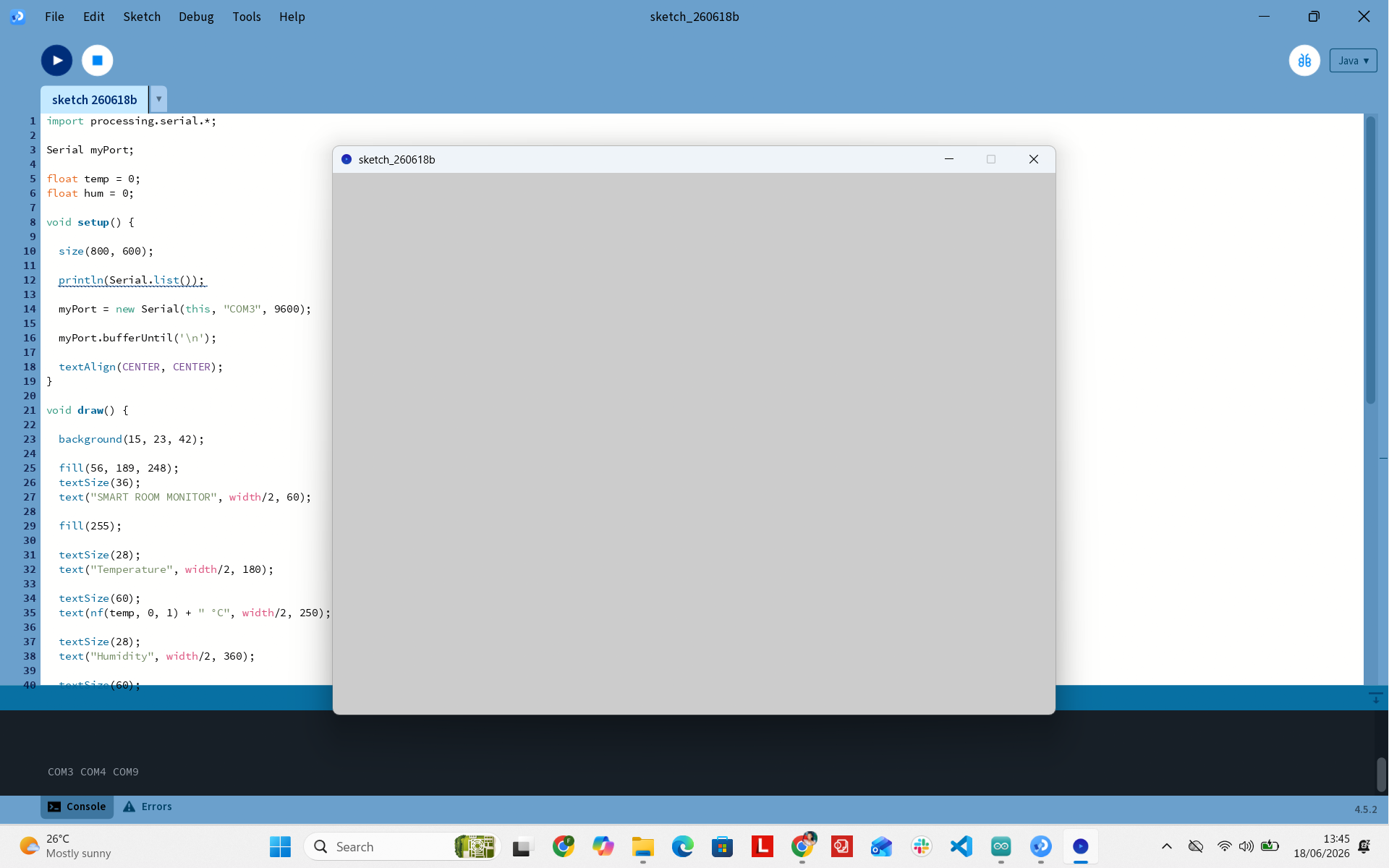
Active GUI environment window dynamically displaying metrics
Communication Protocol
The Arduino Mega communicates with the Processing application over UART Serial at 9600 baud rate.
The DHT22 sensor values are output in comma-separated values (CSV) string format:
28.70,39.70
28.80,39.70
29.20,38.10
29.20,38.10
The Processing sketch uses a serialEvent() interrupt to parse incoming lines, split strings by comma delimiters, convert substrings to floating point values, and update GUI elements dynamically.
Results & Hero Shot
The final system reads live environmental telemetry from the hardware and updates the desktop application GUI dynamically with adaptive color status tags (e.g., COMFORTABLE, HOT, COLD).
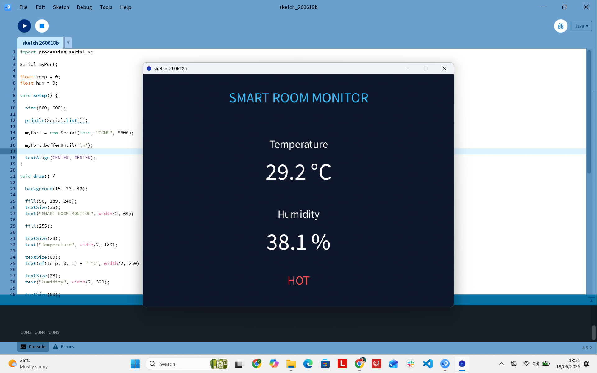
Final Processing Dashboard interface rendering live environmental telemetry
Demonstration Videos
1. Arduino Mega & Serial Stream Output
2. Processing Dashboard Dynamic Updates
Challenges & Solutions
1. Seeed XIAO RP2040 Upload Failure
Problem: The RP2040 board stopped accepting code flashes after several updates.
Solution: Used manual boot-mode recovery sequences, eventually switching platforms when hardware failure persisted.
2. ESP32-S3 Instability & Disconnections
Problem: Sudden serial drops and inability to flash code via USB-C.
Solution: Tested multiple USB-C data cables and ports. Migrated to the Arduino Mega platform for reliable submission.
3. Serial Port Contention
Problem: Processing failed to connect to COM3 when the Arduino Serial Monitor was left open.
Solution: Ensured the Arduino Serial Monitor was closed before initiating the Processing sketch to free port lockups.
What I Learned
- Creating serial data formats (CSV parsing) for cross-platform communication.
- Building desktop GUI applications in Processing using event-driven serial interrupts.
- Systematic hardware debugging techniques across multiple MCU architectures (RP2040, ESP32-S3, ATmega2560).
- Managing serial port constraints when bridging physical microcontrollers to host software applications.
Acknowledgement
I would like to sincerely thank Mazi Armel, Fab Lab Manager and Fab Academy Instructor at UNIPOD Rwanda, for his continuous support throughout this assignment.
I am especially grateful for lending me an Arduino Mega when I encountered repeated hardware issues with both the Seeed XIAO RP2040 and ESP32-S3 platforms. His technical guidance, troubleshooting suggestions, and willingness to share resources enabled me to successfully complete the assignment.