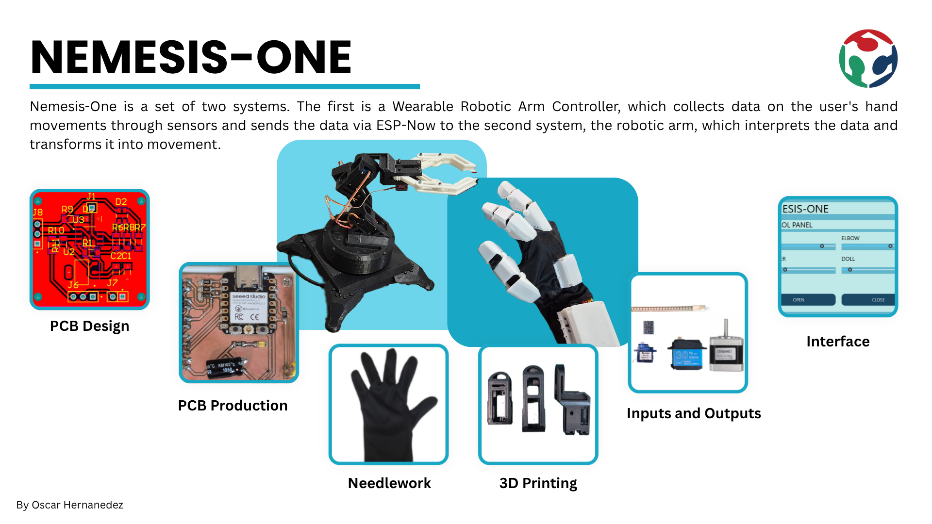
The goal of this project was to develop a portable control interface capable of operating a robotic arm in near real-time. By integrating motion tracking and flexion detection, the system offered an intuitive, human-like control experience, bridging the gap between user intent and mechanical execution. Beyond simple movement, this technology aimed to decentralize the machine operator, enabling complex tasks to be performed from a safe distance or in specialized environments.
The inspiration for this project came from an earlier prototype: a wired glove for controlling a mouse. While that initial version successfully demonstrated the basic concept of gesture-based input, it was limited by its physical connection. My goal for the Fab Academy was to build this concept into a fully wireless system with optimized signal processing. This transition from a simple wired tool to a sophisticated wearable controller represented a significant personal achievement.
Design Considerations and Challenges
To manage the development of this project, I established a structured schedule based on the Fab Academy's weekly requirements, defining specific goals and delivery dates for each phase.

Bill of Materials and Components
Electronics and Mechanical
| Component | Qty | Where I got it | Approx. price (USD) | Link |
|---|---|---|---|---|
| XIAO ESP32-C3 (glove microcontroller) | 1 | Mercado Libre | ~$10.50 | View product |
| XIAO ESP32-C6 (arm microcontroller) | 1 | Mercado Libre | ~$13 | View product |
| Flex sensor 2.2" | 3 | Mercado Libre | ~$17.50 | View product |
| MPU6050 (GY-521) IMU module | 1 | Mercado Libre | ~$4.50 | View product |
| NEMA 17 stepper motor | 1 | Mercado Libre | ~$16 | View product |
| DRV8825 stepper driver | 1 | Mercado Libre | ~$5 | View product |
| Servomotor 8125mg | 3 | Mercado Libre | ~$45 | View product |
| XL4016 step-down voltage converter | 1 | Amazon México | ~$10 | View product |
| 12V power supply | 1 | Mercado Libre / Amazon | ~$17.50 | View product |
| On/Off rocker switch | 1 | Mercado Libre | ~$2.50 | View product |
| Dupont & pin connector kit | 1 kit | Mercado Libre | ~$8.50 | View product |
| Copper plate | 2 | Steren | ~$5 | View product |
| PLA filament (1 kg, 3D printing) | 1 | Mercado Libre / Amazon | ~$20 | View product |
| Lycra fabric (for the glove) | ~0.5 m | Parisina | ~$1 | View product |
Screws and Nuts
All of the screws below were used together with their matching nuts. I bought them from a local hardware store (tornillería), which worked out much cheaper than buying them individually online.
| Screw size | Qty | Nuts |
|---|---|---|
| M5 × 30 | 1 | Yes |
| M4 × 20 | 16 | Yes |
| M4 × 10 | 12 | Yes |
| M3 × 30 | 2 | Yes |
| M3 × 20 | 20 | Yes |
| M3 × 15 | 4 | Yes |
| M3 × 10 | 16 | Yes |
| M3 × 5 | 3 | Yes |
| M2 × 8 | 2 | Yes |
| M2 × 5 | 3 | Yes |
| Total screws | 79 | + 79 nuts |
| Estimated total (incl. ~$5.50 in fasteners) | ~$180 USD |
Glove Electronics Design
For this part of the project, I used Altium Designer as my main tool for circuit design. I focused on creating dedicated modules for each system function, such as the main control module, the power module for the arm actuators, the battery and charging module, and the sensor module. This modular approach allowed me to better organize the design and made the fabrication of each part much easier.
For the glove, I designed 5 PCBs: two main boards that controlled the system's operation, housing the XIAO ESP32-C3 and the battery/charging circuit, and three smaller breakout boards, one for a button connected to the XIAO, another for the MPU6050 pins, and individual boards for each flex sensor.
Xiao ESP32-C3 PCB
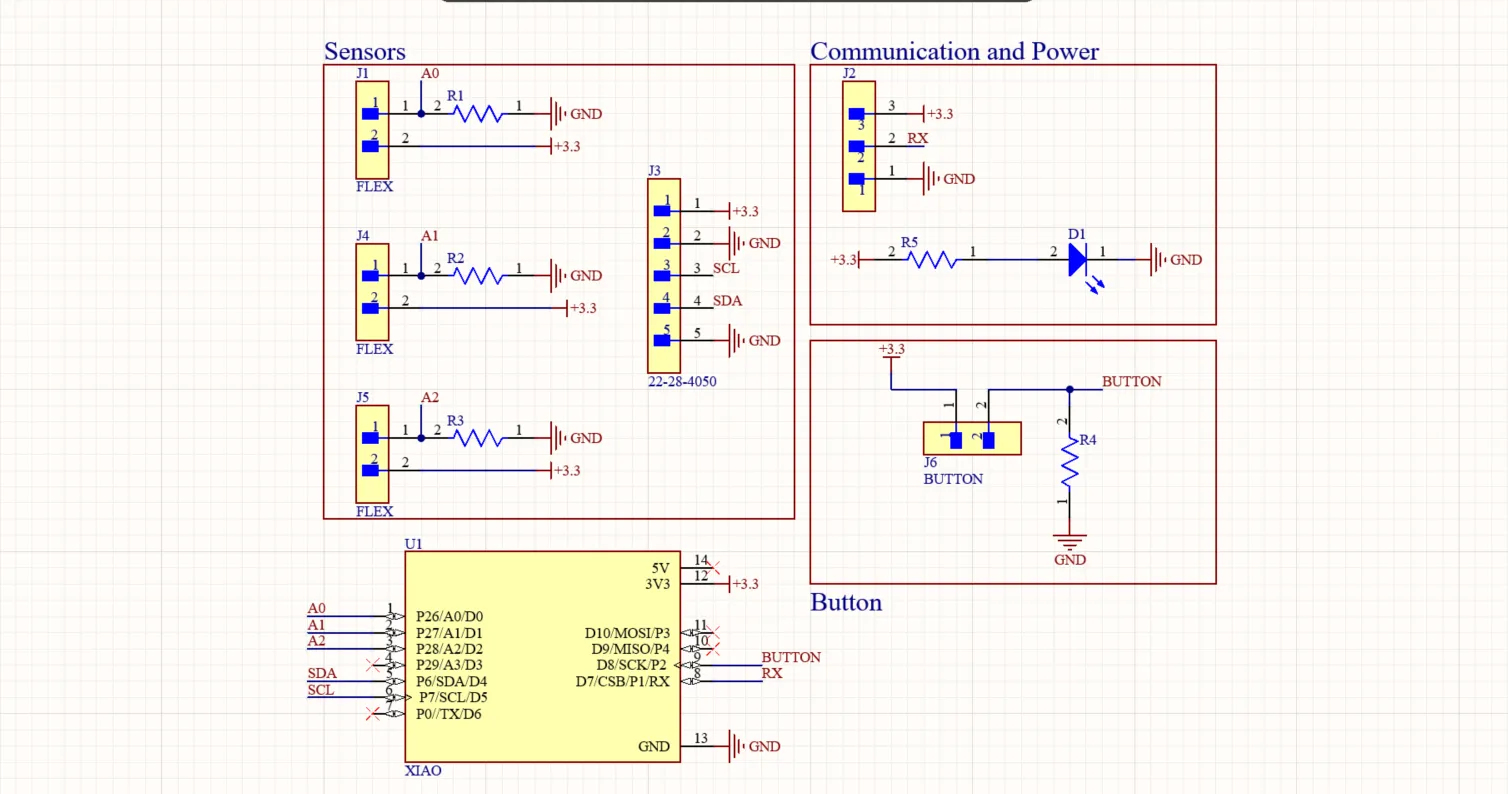
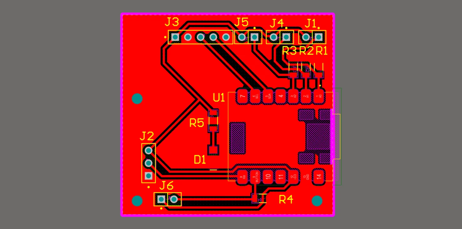
This PCB integrated the XIAO ESP32-C3 along with the necessary resistors for each flex sensor and the button. It also featured a power LED and headers to connect the battery and charging module, the MPU6050 module, and the flex sensors. This board was responsible for processing all the sensor data and sending the control signals to the robotic arm's actuators.
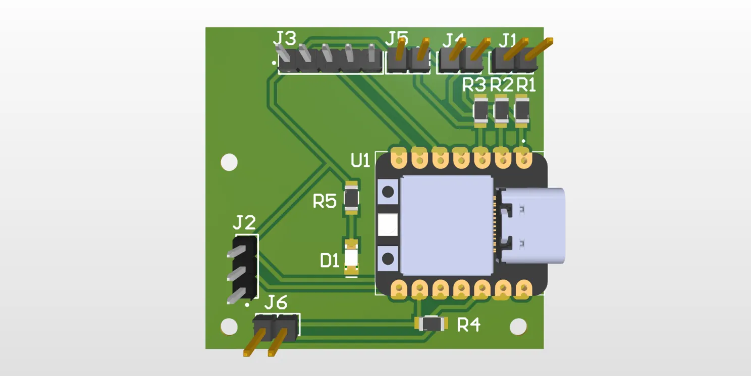
Battery and Charging PCB
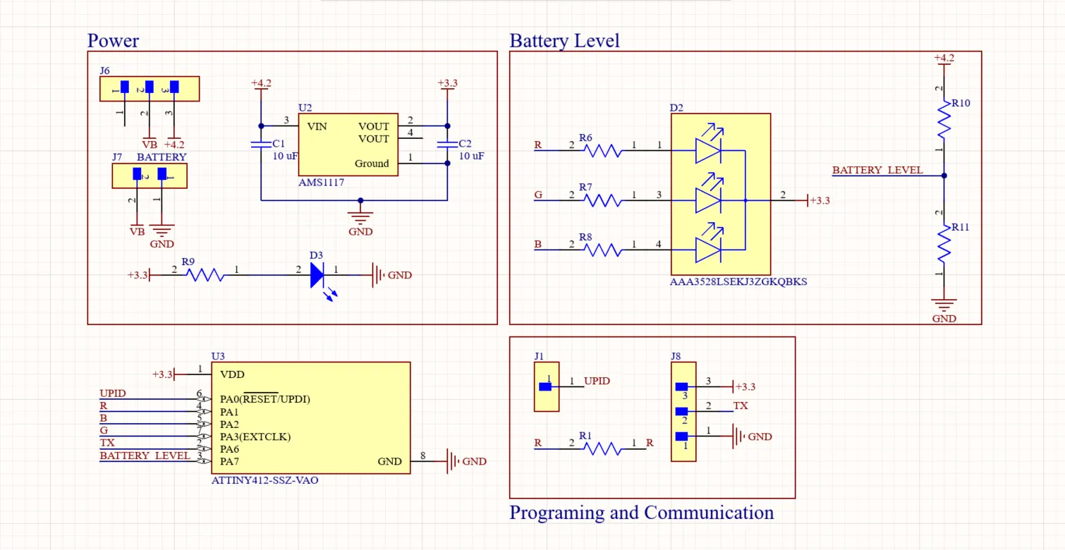
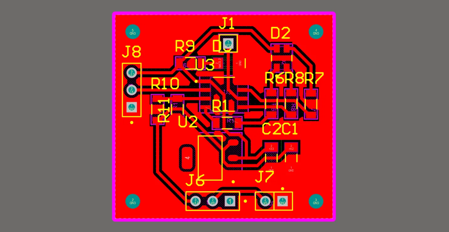
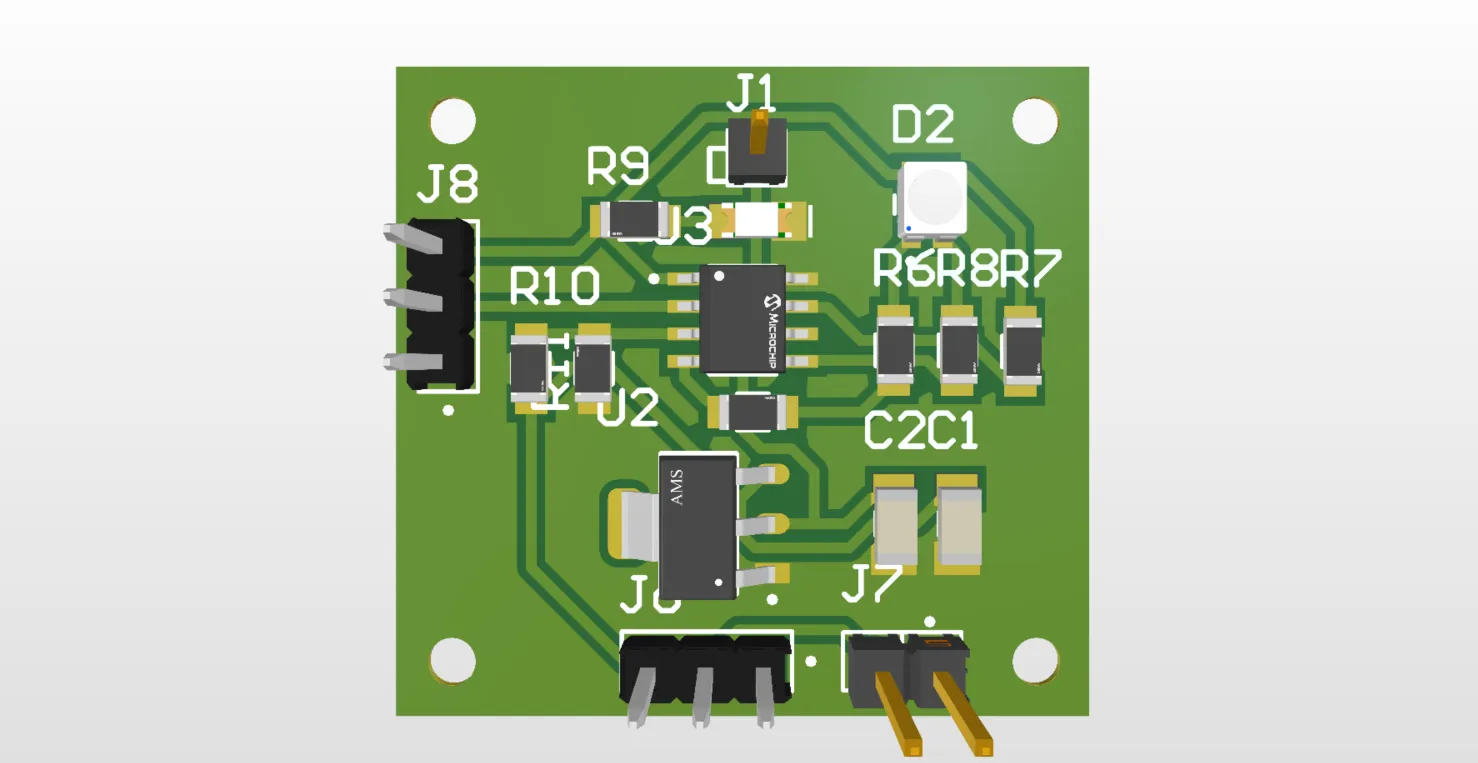
This board was responsible for managing the system's power and included an ATtiny412 as its controller. An RGB LED was connected to it to indicate the battery level, and I created a voltage divider connected to an analog pin and the battery to monitor its voltage. I also left headers to connect a TP4056 charging module, which charged the battery and powered the system through a voltage regulator that stepped down the 5V from the TP4056 to the 3.3V required by the XIAO ESP32-C3.
However, as I learned during my research, it was necessary to implement a Load Sharing circuit using a P-Channel MOSFET, a Schottky diode, and a resistor between the module, the battery, and the glove's electronics to allow the glove to be safely used while charging. This was a feature I still needed to implement; without these components, the LiPo battery could get stressed and swell. It was also important to mention that I included RX and TX communication pins to send battery data to the main microcontroller. This communication channel was unidirectional, sending information only from the battery board to the main board. Finally, I added a UART programming pin to easily upload code to the ATtiny412.
Sensors and Button PCBs
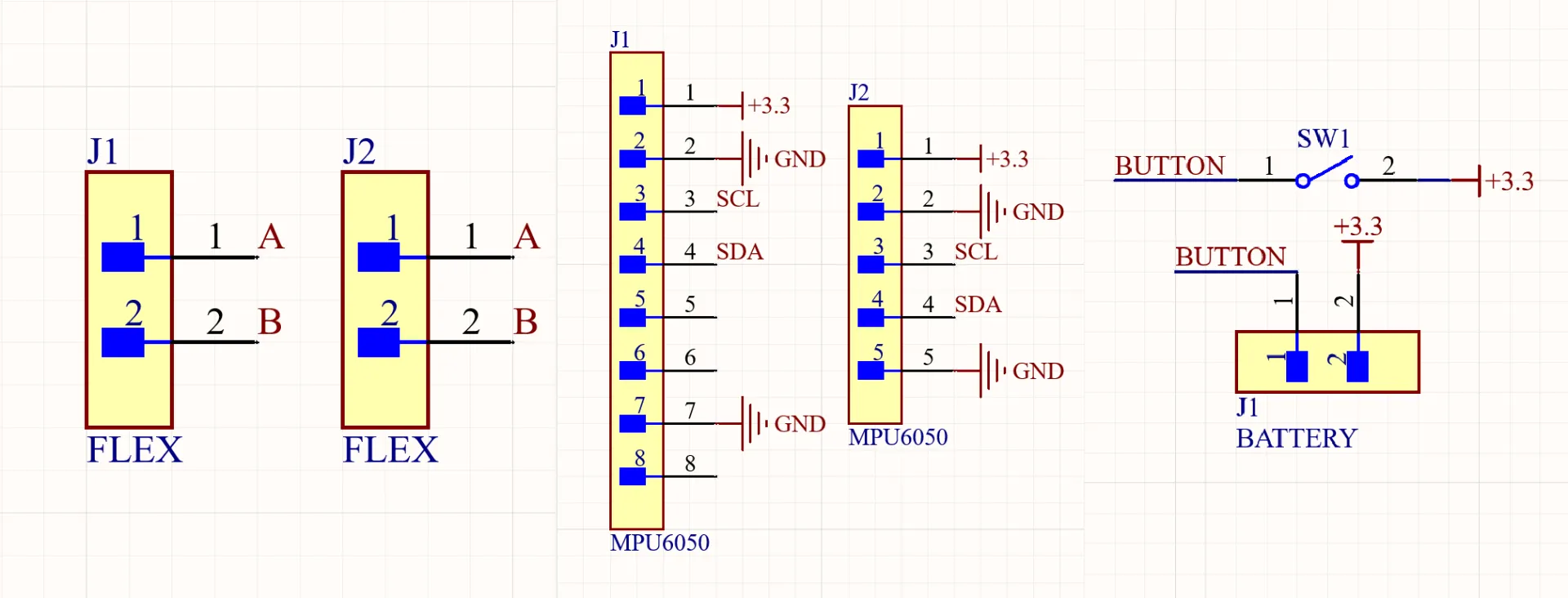
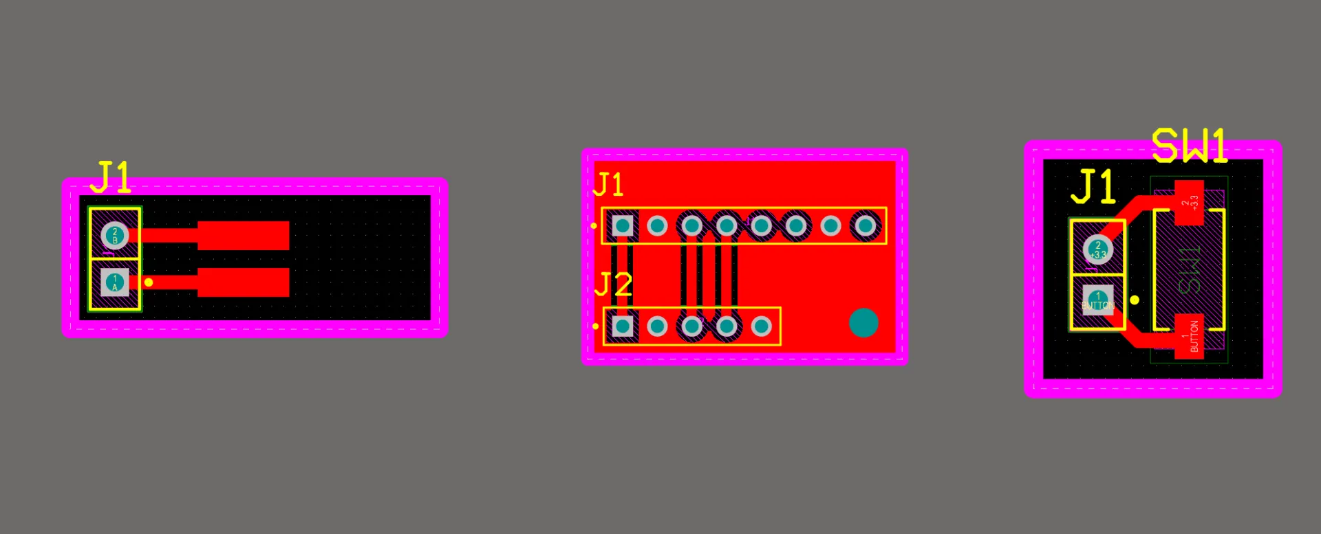
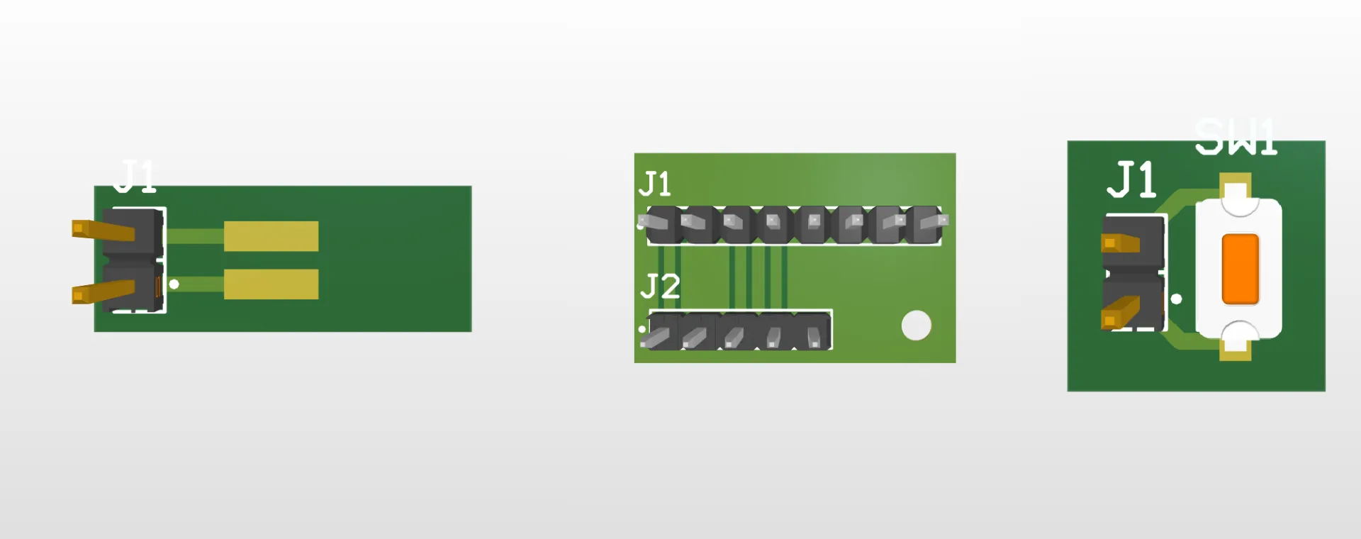
These PCBs were quite simple, as they acted mainly as breakout boards to route the sensors to headers for an easy connection to the main microcontroller.
All grounds from every component had to be unified.
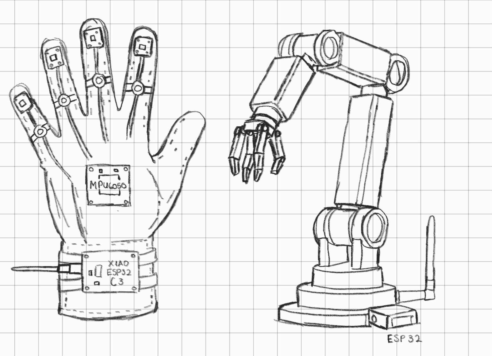
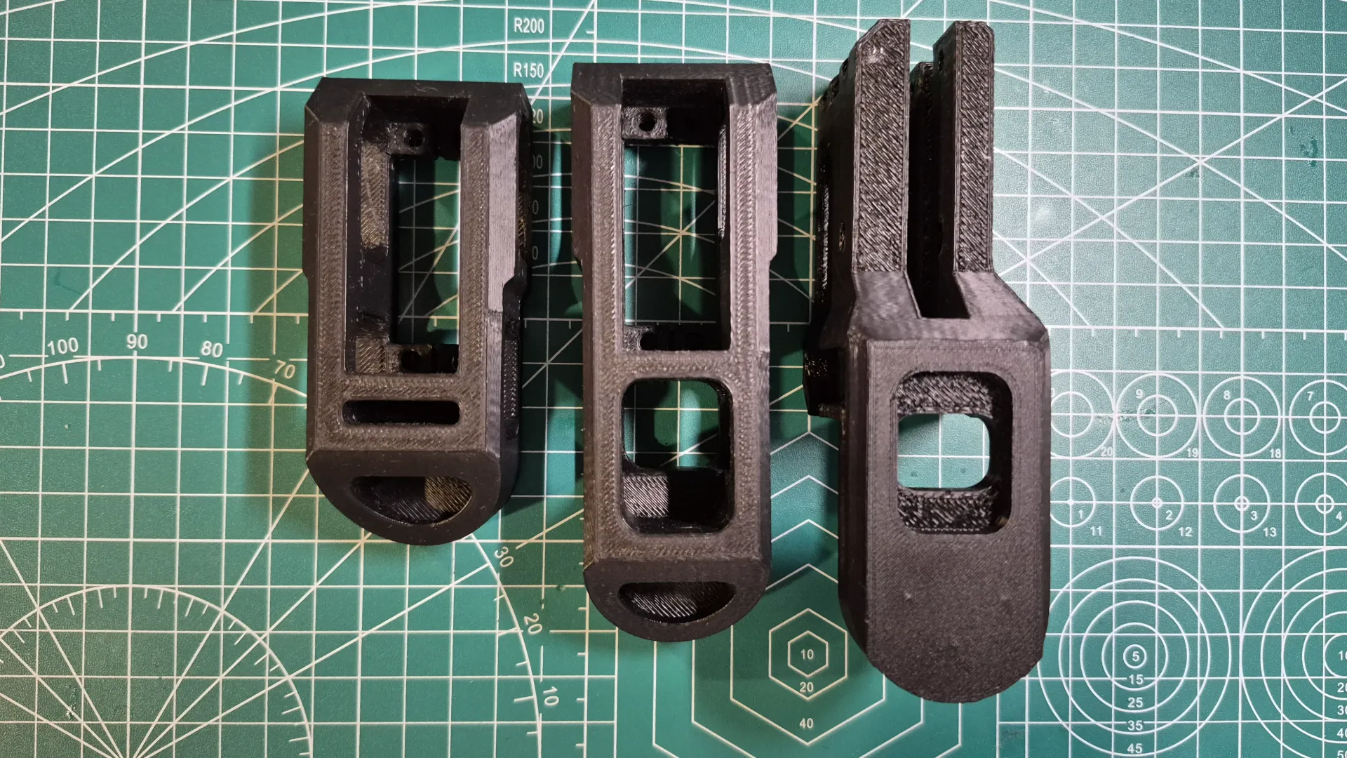
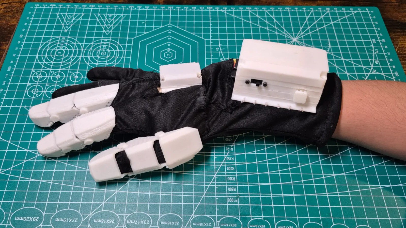
Glove 3D Design
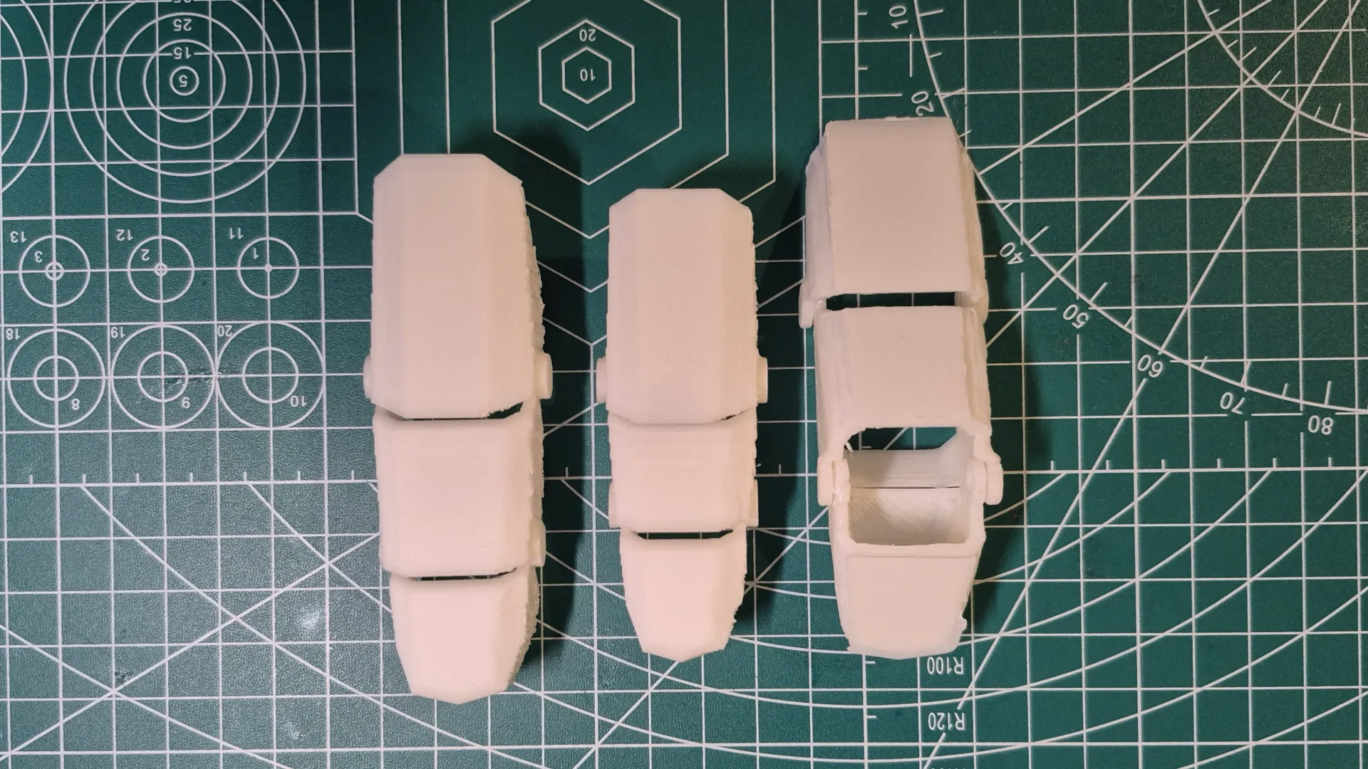
The design of the finger pieces was based on a medieval armor gauntlet. This structure provided the necessary mobility for manipulation tasks and kept the sensors securely in place while in use. Personally, I also found this design quite visually appealing.
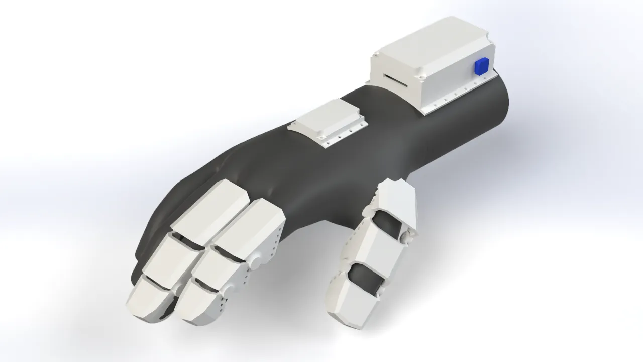
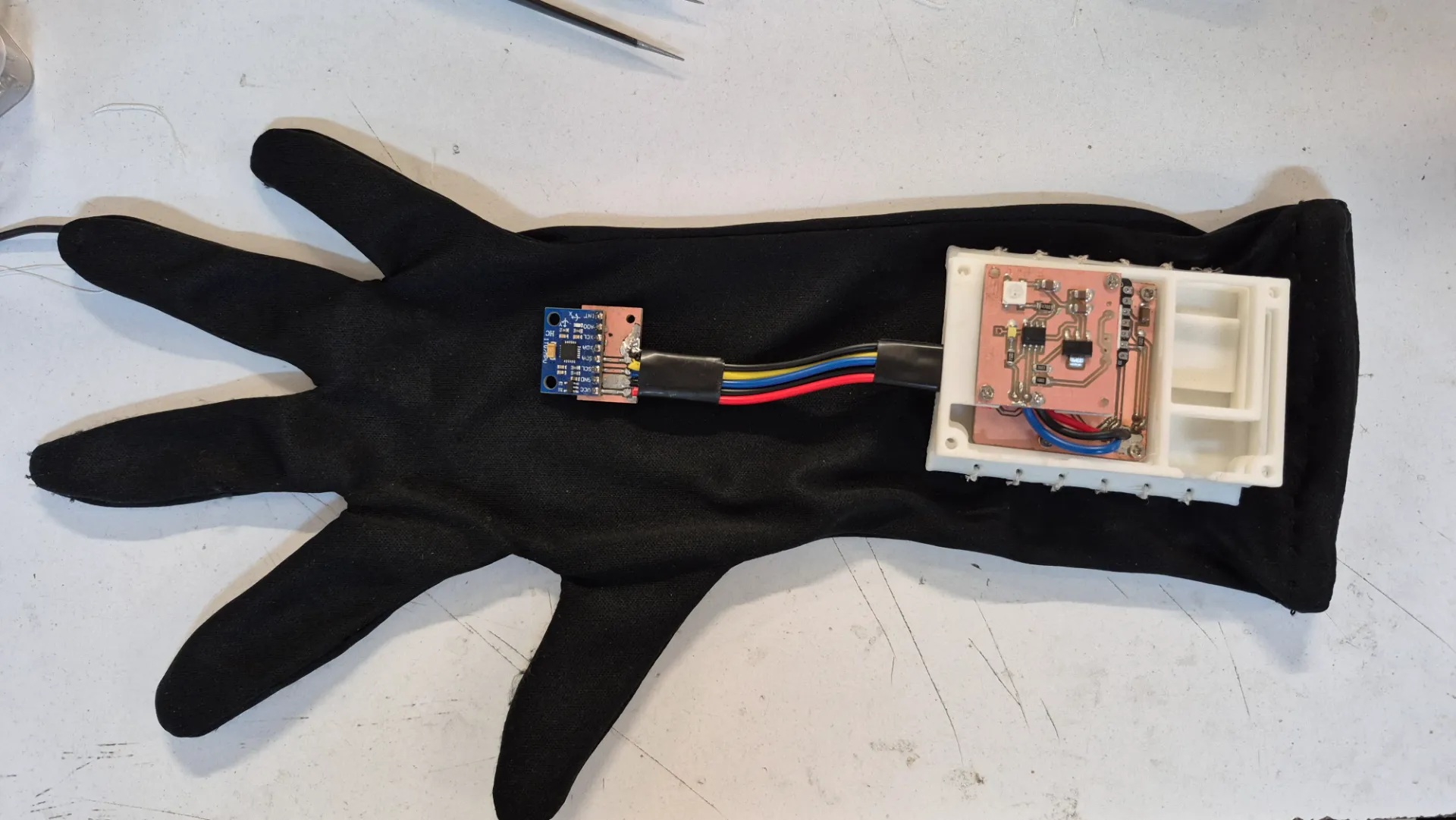
I also designed a couple of compartments for the glove's electronics. The wrist section housed the main PCBs, such as the XIAO ESP32-C3, along with the battery level indicator board and the charging circuit. The MPU6050 motion sensor was placed on the back of the hand so it could accurately capture hand movements and transmit them to the robotic arm.
Bracelet
The bracelet accommodated the electronics in such a way that the microUSB port remained easily accessible for charging the battery and programming the microcontroller, without needing to take the bracelet apart. Additionally, I added a side button for various actions, like turning the glove on or switching control modes. The bracelet was designed with user comfort in mind, featuring an ergonomic shape that adapted to the wrist and holes to sew the piece directly onto the fabric of the glove.

MPU6050 Case
Just like the bracelet, the MPU6050 case securely housed the electronics. It included a hole for the power and communication wiring, and it was designed to be as compact as possible to minimize the weight on the back of the hand. The case featured sewing holes to attach it to the glove, as well as screw holes to hold the motion sensor firmly in place and prevent it from shifting during use.
Fingers
The finger covers were designed so that the sensors stayed perfectly in place when flexing and extending the fingers. Like the rest of the components, these covers had holes to be sewn onto the glove. I took into account the ergonomics of the fingers and their bending angles to shape these pieces properly.
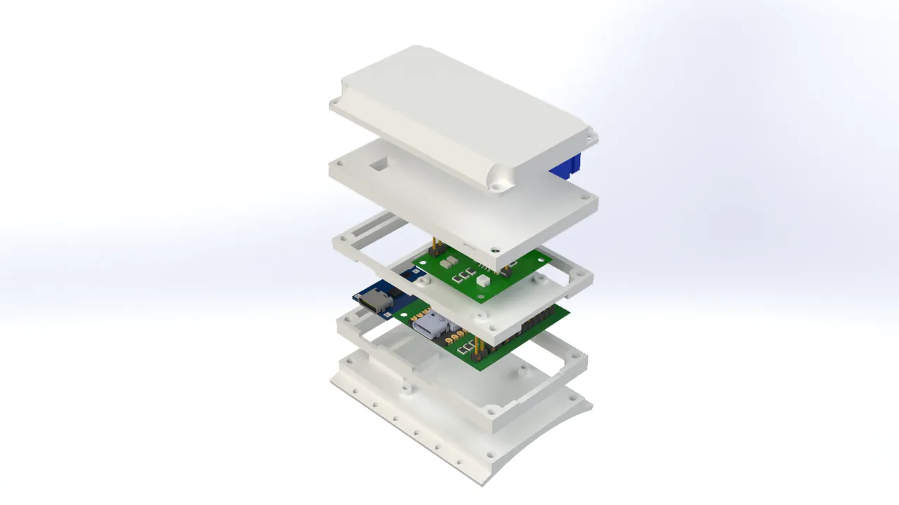
Robotic Arm Electronic Design
For the robotic arm's electronic design, I opted for a modular model like the one for the controller glove. This was to prevent possible material waste in case any part of the design did not work correctly, and it also allowed me to better organize the design and fabrication of each part. The arm featured a main module housing a XIAO ESP32-C6, which was in charge of receiving information from the glove and controlling the arm's actuators; a power module to distribute energy among the PCBs; a board to connect the servos based on the PCB I made during outputs week; and a module for the stepper motor driver.
Brain PCB
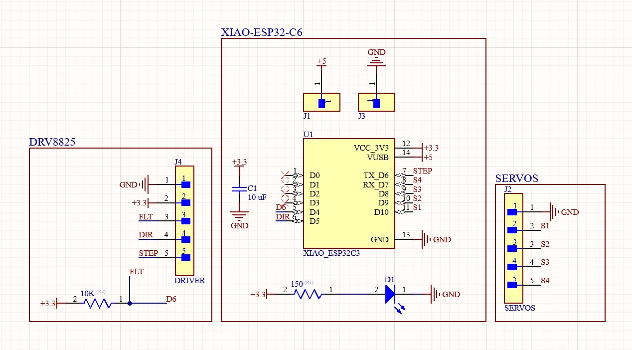
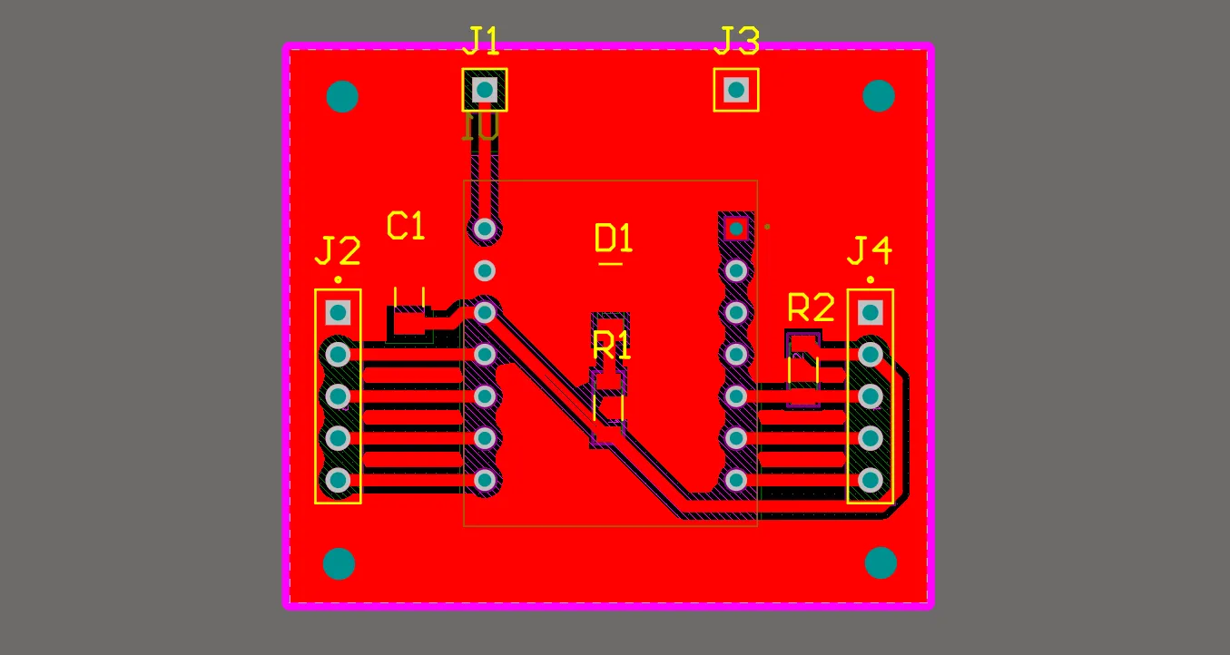
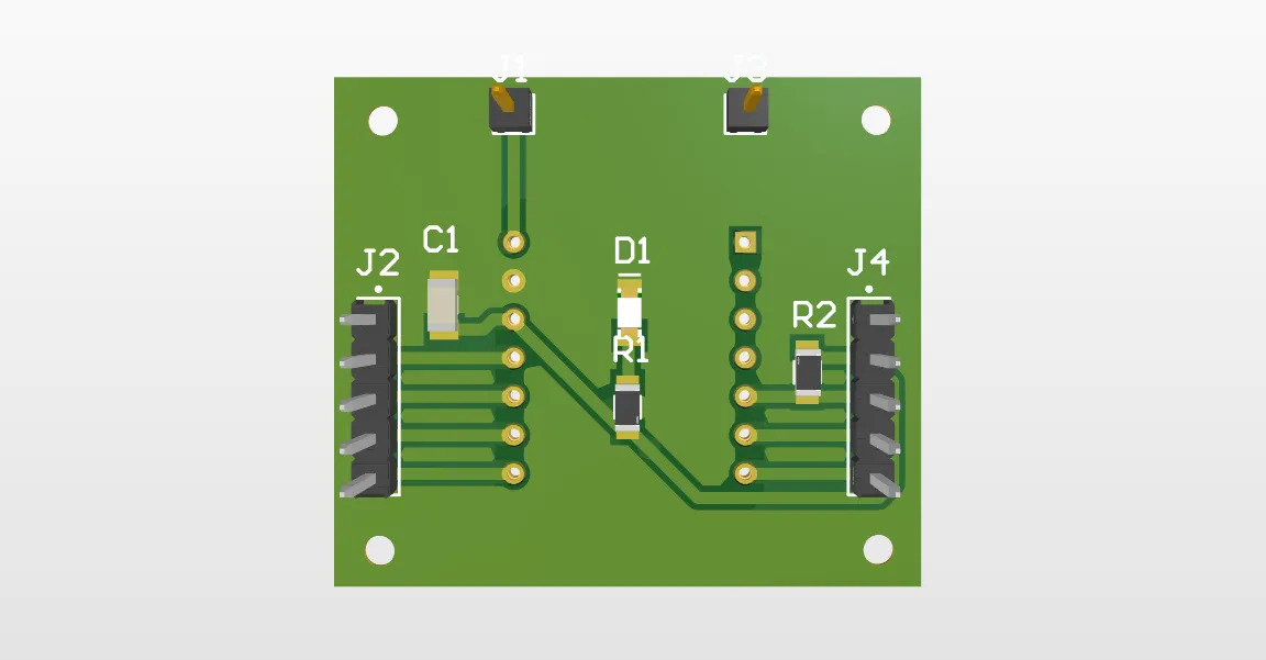
The brain of the robotic arm consisted of a removable Xiao ESP32-C6 with male and female pins; I did this to facilitate repairing the board in any unexpected situation. I placed a 10uF decoupling capacitor to prevent voltage drops caused by the current spikes generated by the ESP-NOW communication. I also placed a pull-up resistor necessary for the driver's FLT pin, which indicated if there was any failure in the NEMA system. In addition, I included a power indicator LED and multiple headers to connect all the other PCBs.
Power Distribution PCB
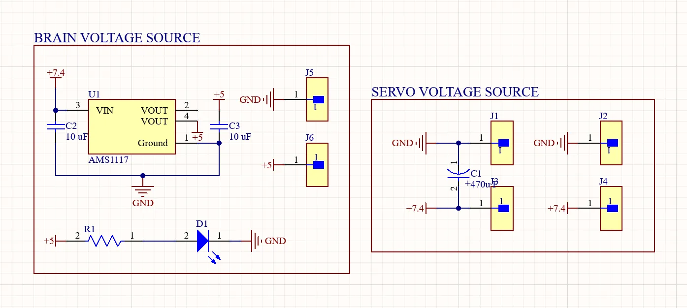
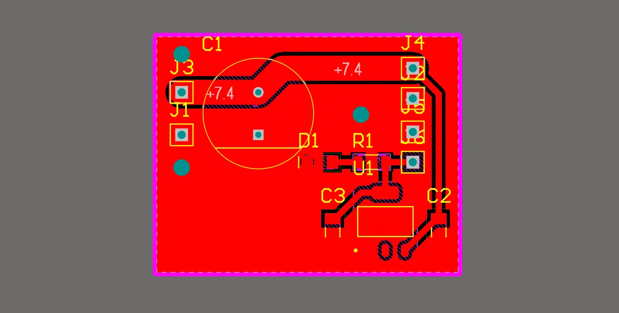
This board distributed the voltage to the different components of the system. It had a 7.4V input and output to power the servomotors, and it also contained an AMS1117 5V voltage regulator to power the arm's brain.
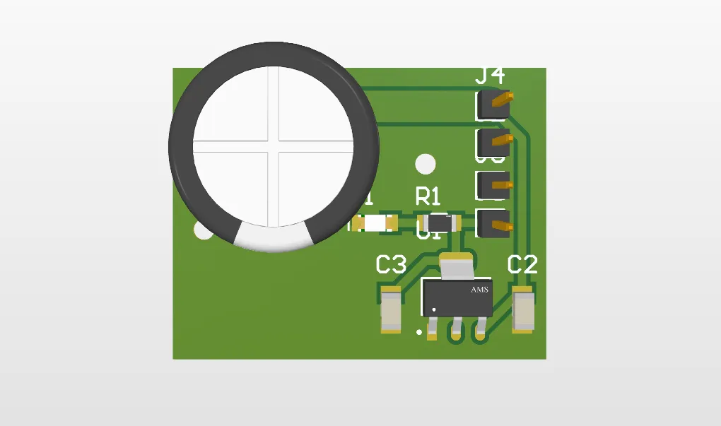
Servo Driver PCB
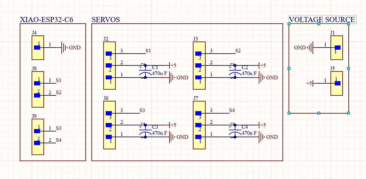
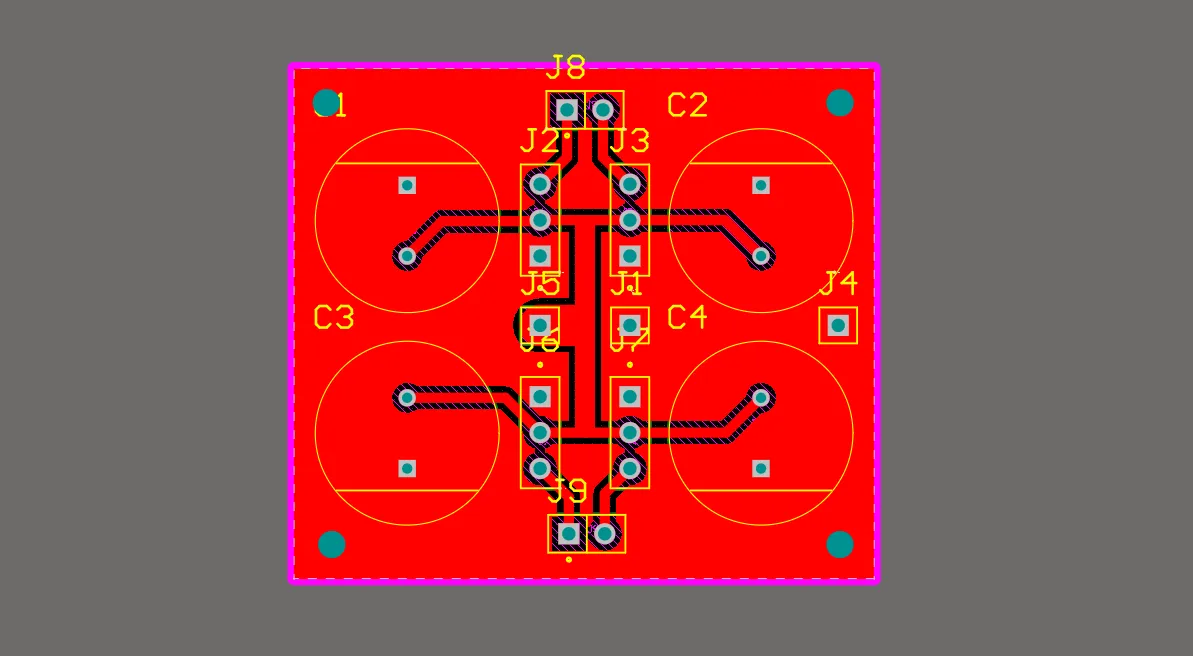
This PCB was designed to connect the servos to the 7.4V power supply and the PWM signals generated by the brain. I placed a 470uF capacitor for each servo to prevent voltage drops due to the current spikes generated by the servos when moving. This design was inspired by the board I made for outputs week; I simply added more channels to be able to connect 4 servos.
Output Week 10
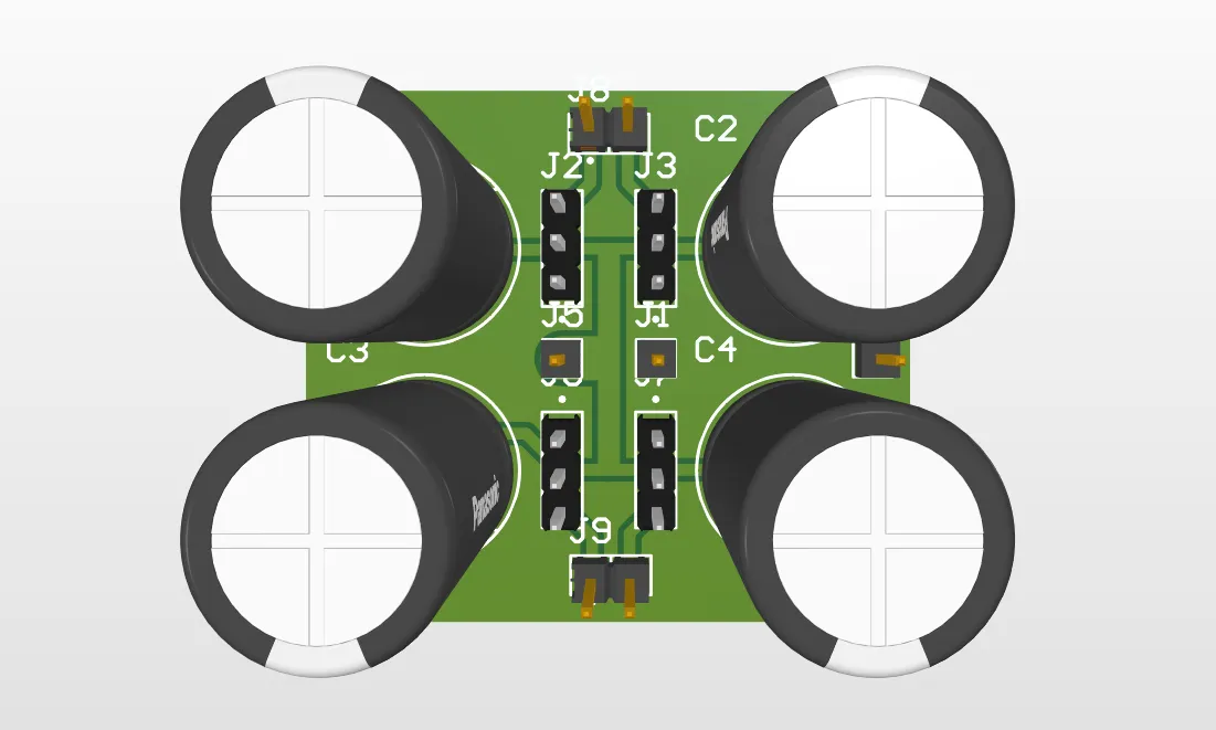
Stepper Motor Driver PCB
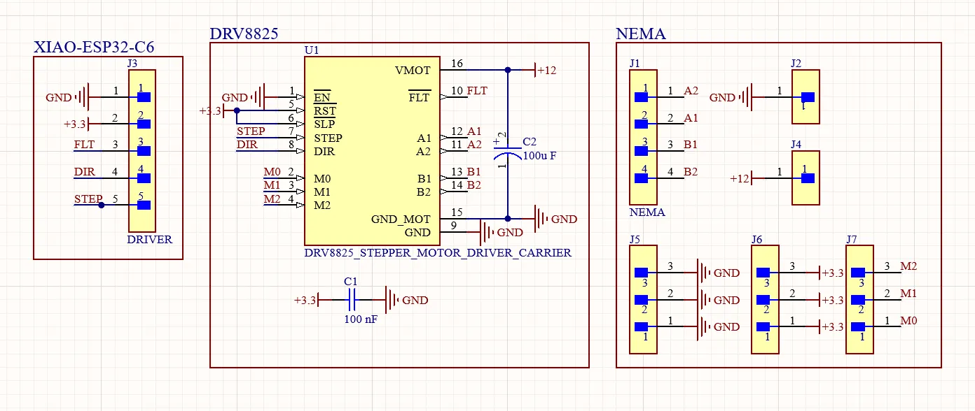
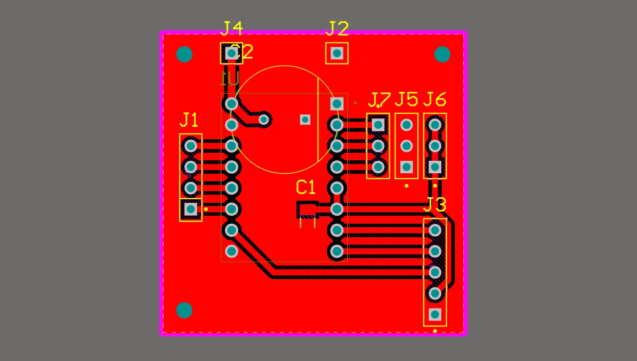
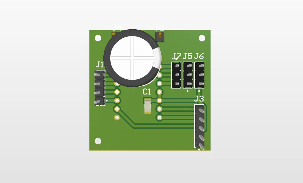
This PCB was designed to connect the driver's logic pins to the brain, manually set the NEMA microstepping divisions with jumpers (M1, M2, M3), and it also featured terminals to power the motor with 12V.
All grounds from every component had to be unified.
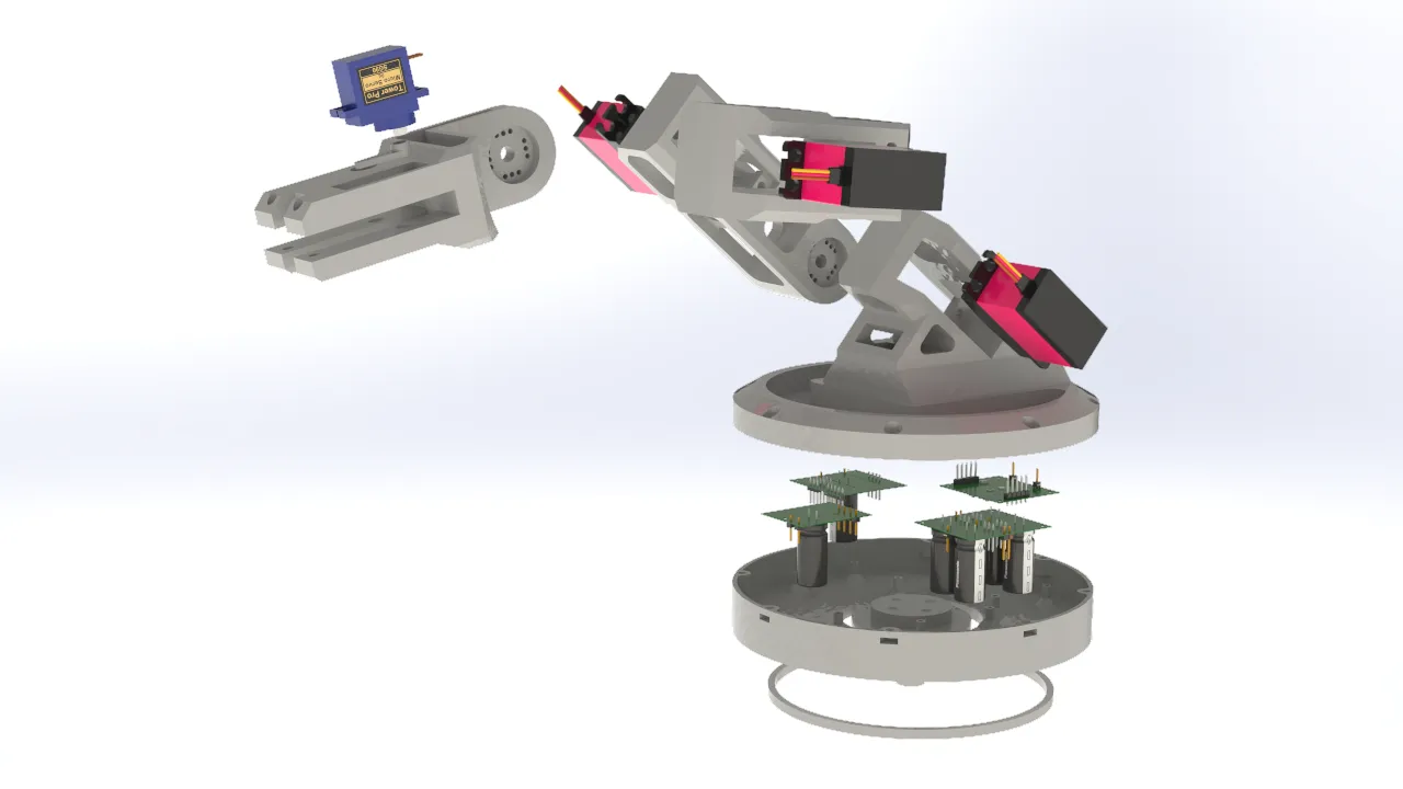
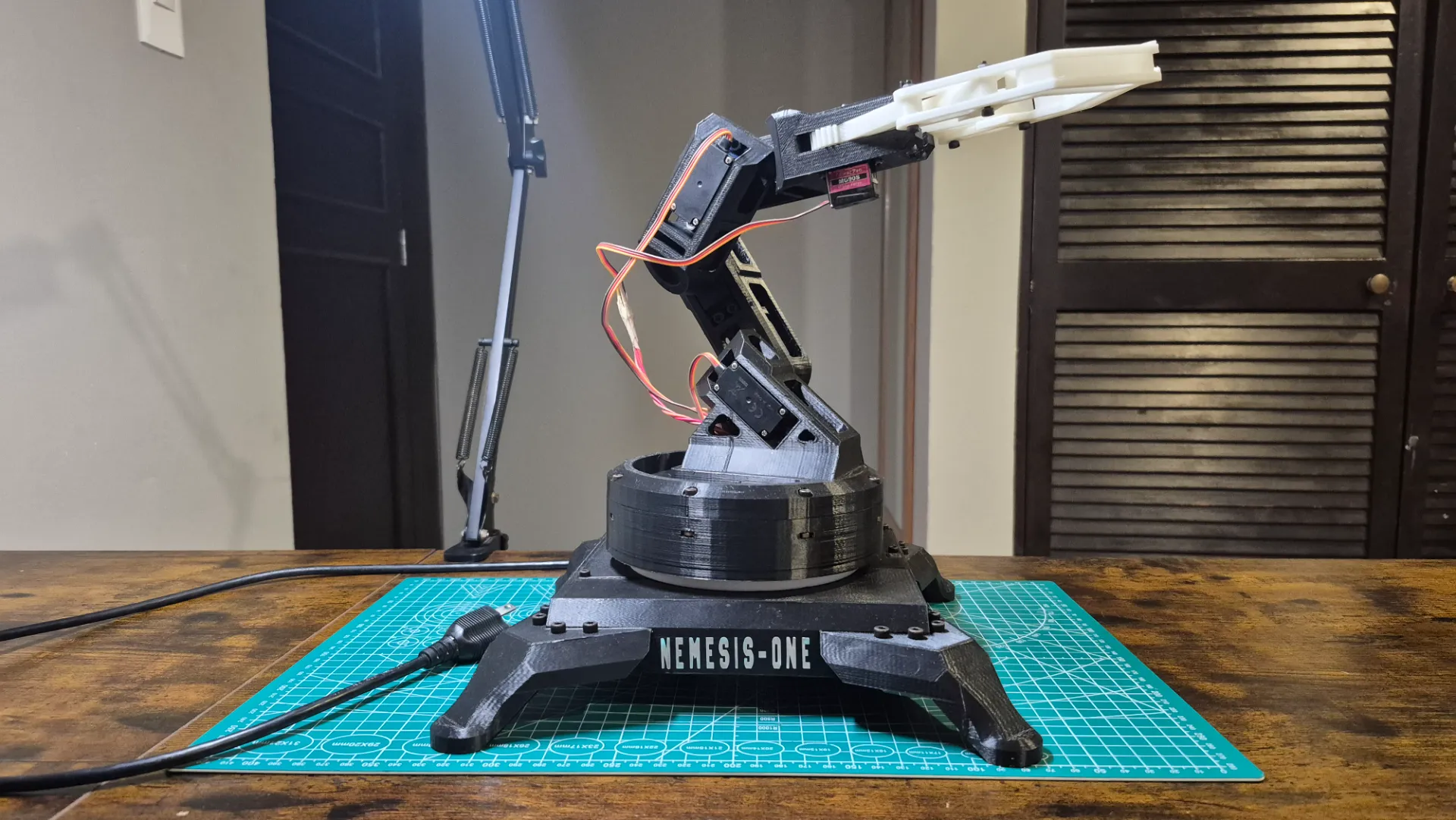
Robotic Arm 3D Design
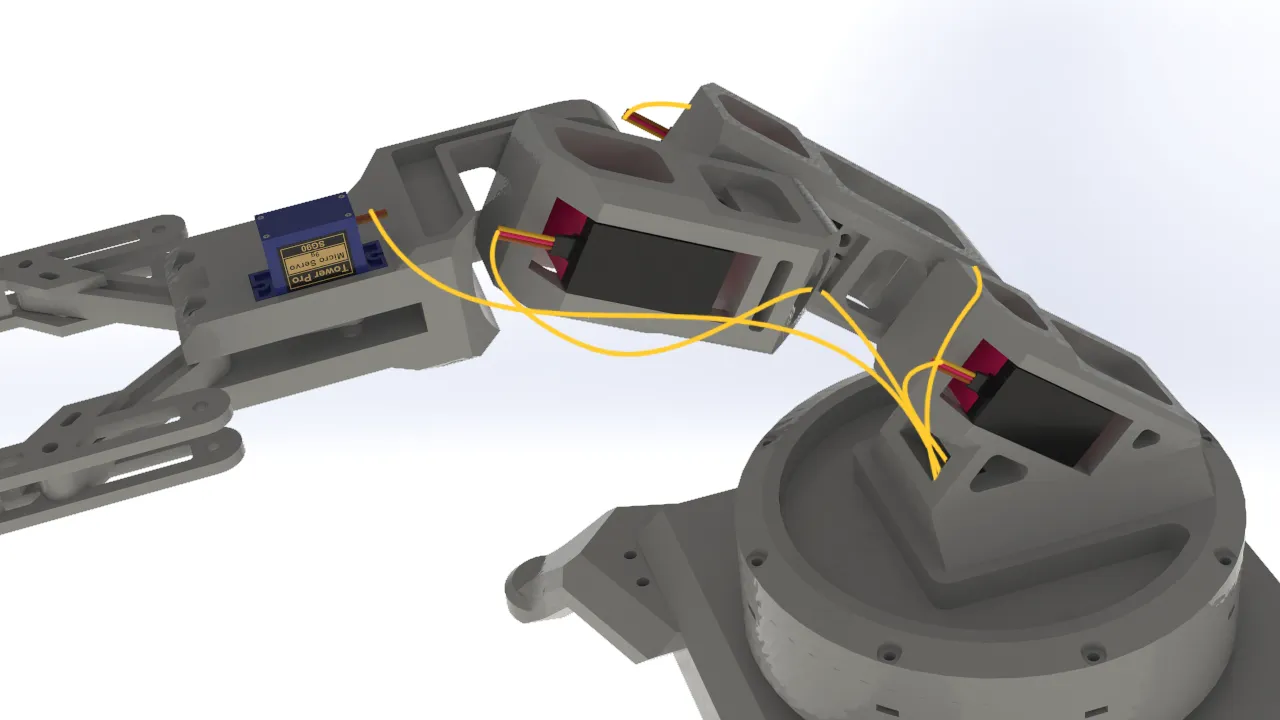
For the robotic arm design, I focused on the mobility of the joints, since the servos I used offered a 270° degree of freedom. I also prioritized keeping the parts as lightweight as possible in order to minimize the arm's total weight, preventing the servos from being strained by the torque required to move it. This approach also had the added benefit of maximizing the load the gripper could carry.
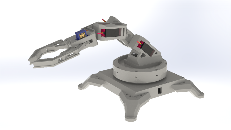
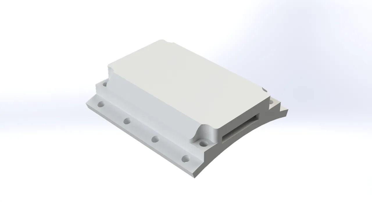
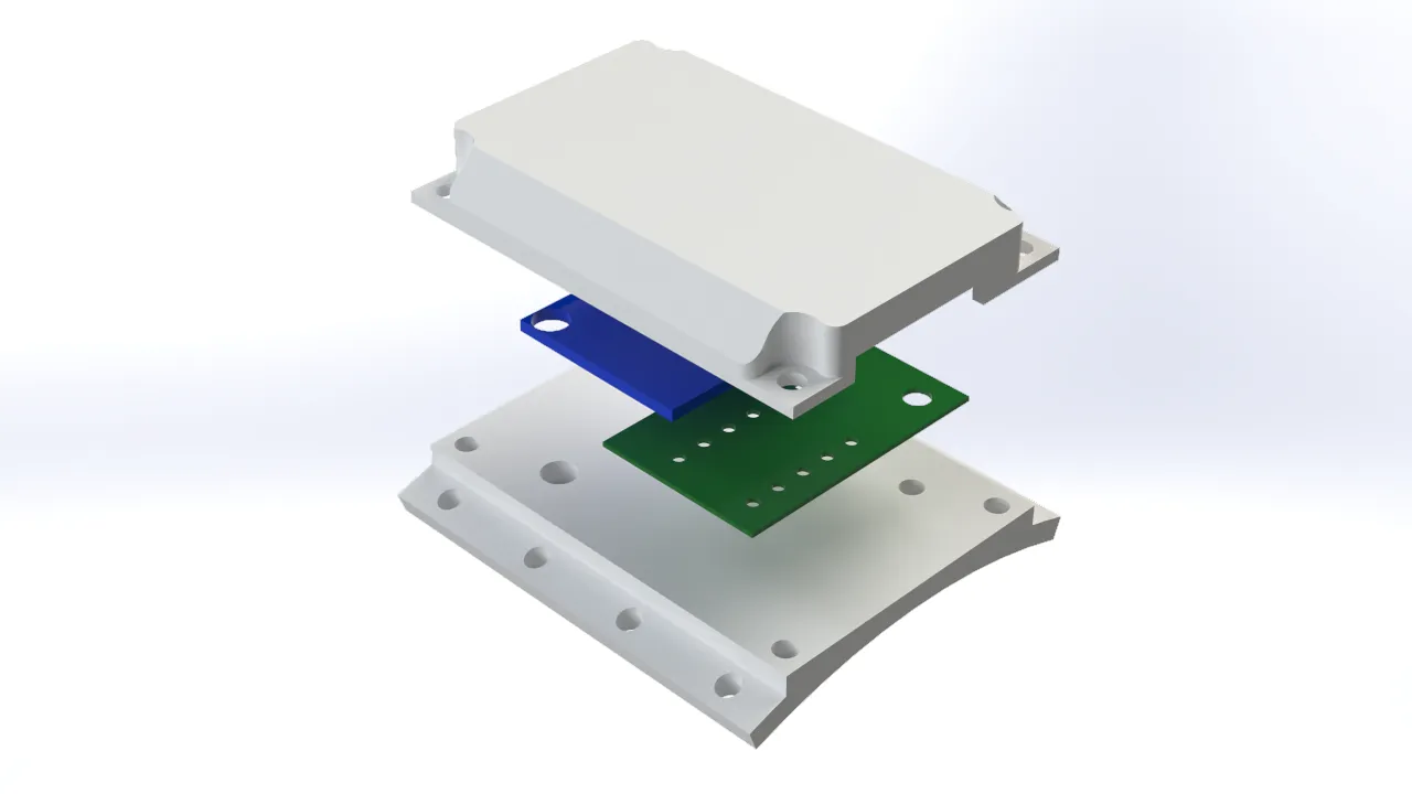
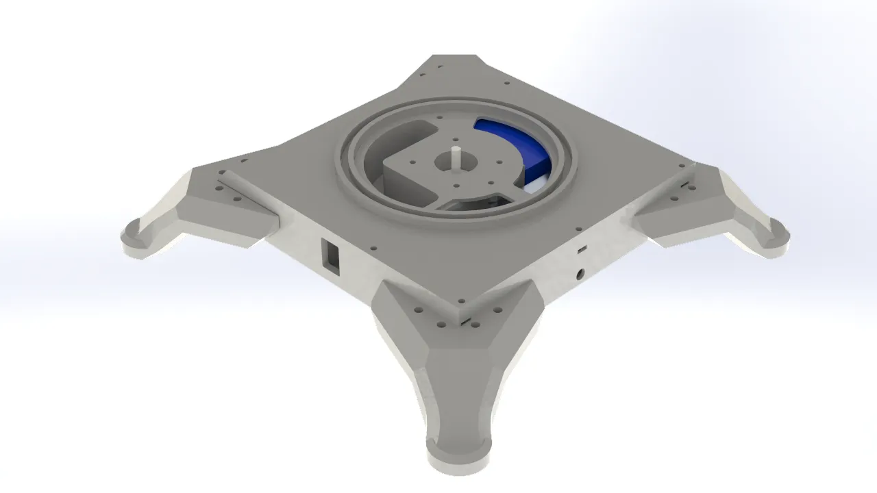
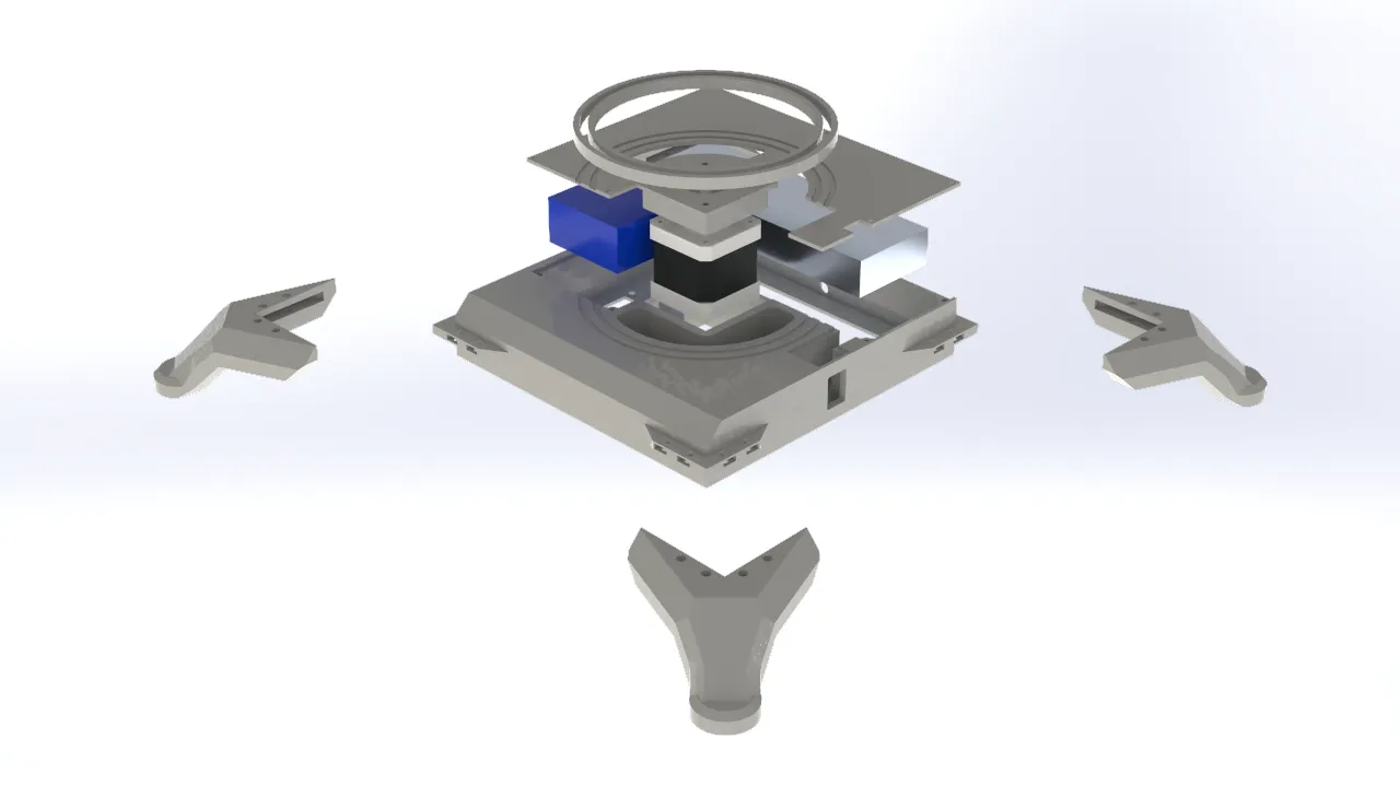
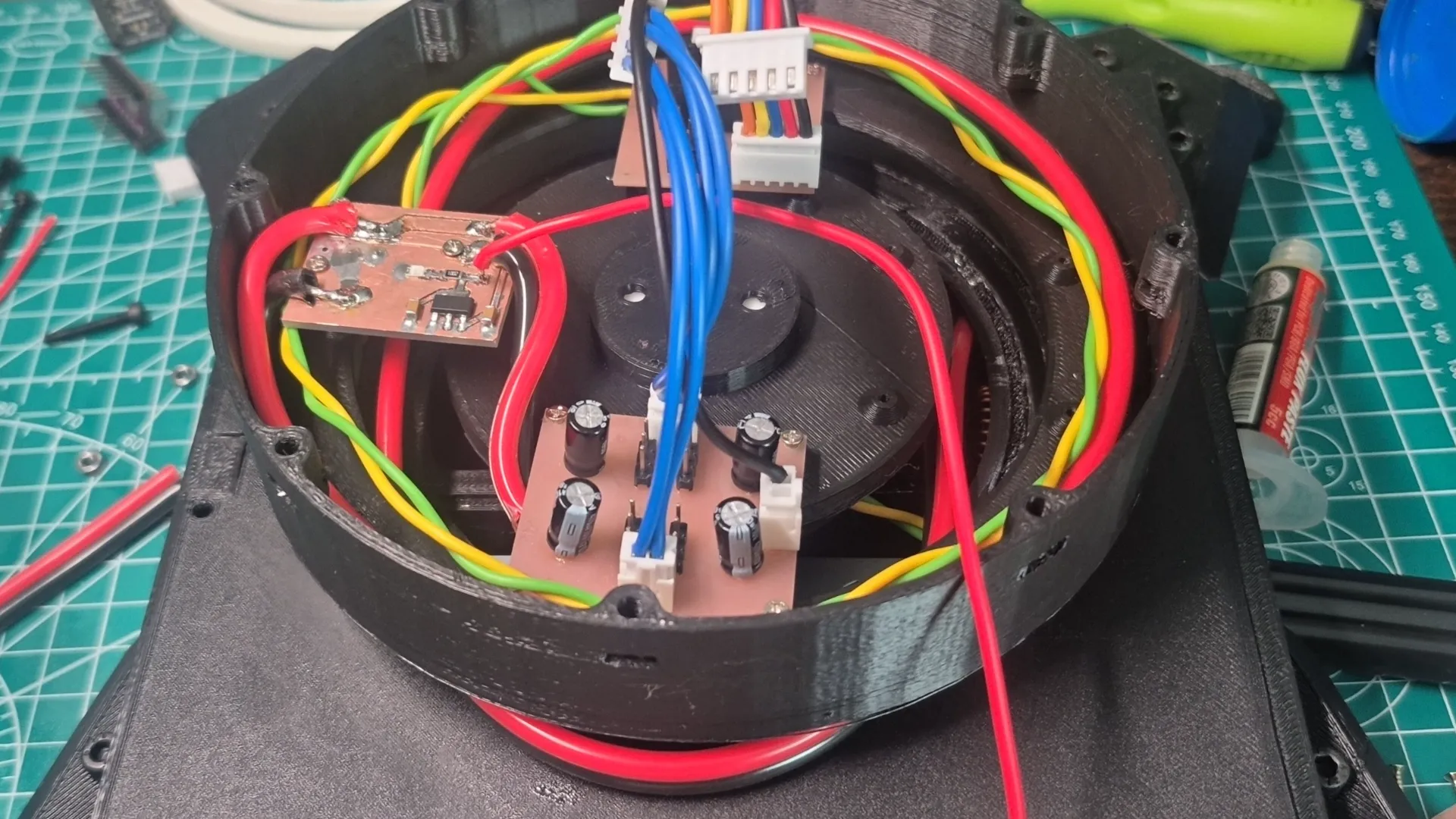
Base
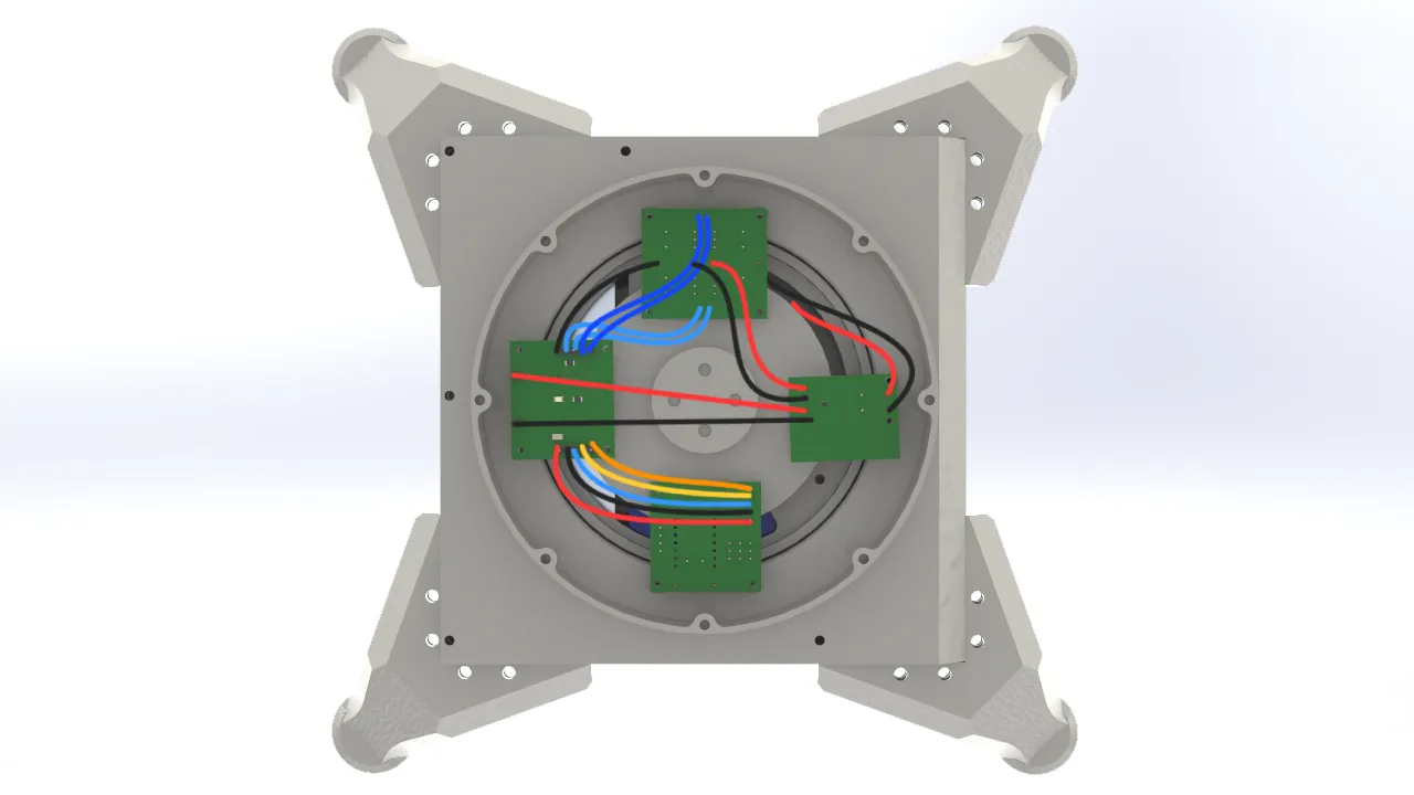
When designing the robotic arm's base, I took into account all of the electronics that would be integrated into the system. I designed a square enclosure with dedicated space for a 12V power supply, which was necessary to power the entire system. I also incorporated an XL4016 voltage reducer to step the voltage down to 7V for the servomotors, along with space for an On/Off switch to safely cut power to the system. Finally, I allocated space for the Nema stepper motor responsible for the arm's rotation. To allow the components to connect with the rest of the structure, I added through-holes that communicated with the rest of the assembly.
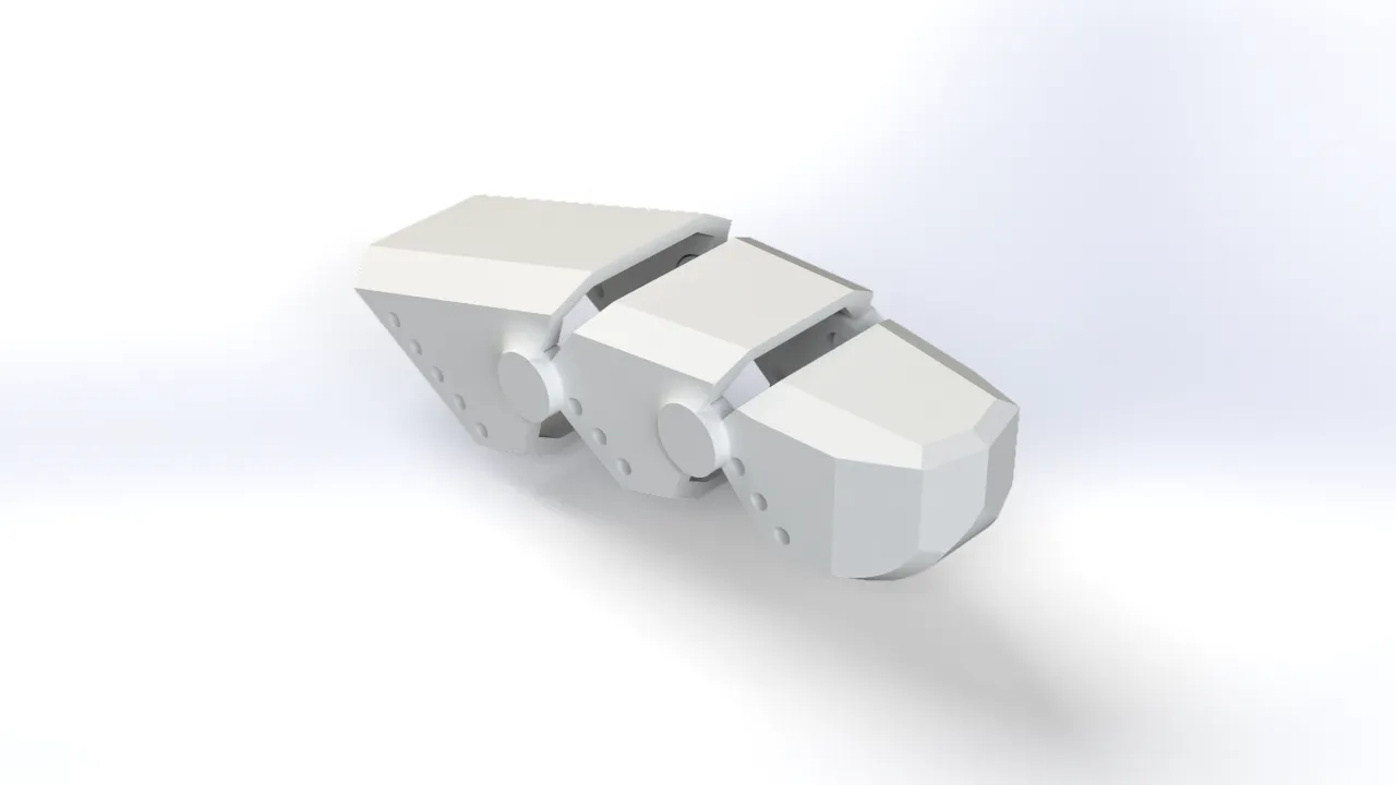
Articulations
For the robotic arm's joints, I considered the range of motion of the servomotors and carefully accounted for potential collisions between parts to ensure interference-free movement. I also identified and removed excess material from non-functional areas of each part to reduce the overall weight the servos would need to lift. For the mechanical connections, I used the brackets included with the servomotors, which were screwed directly onto the printed parts and secured with an additional bolt to keep each joint stable. Regarding the electronics, I placed them in the lower section of the rotating base. This decision was made with the arm's movement in mind, since cable routing could otherwise be affected by the rotation, having both the electronics and the structure rotate together was the most practical solution.
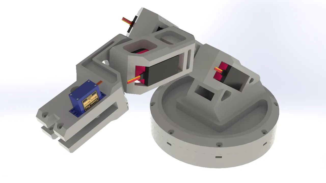
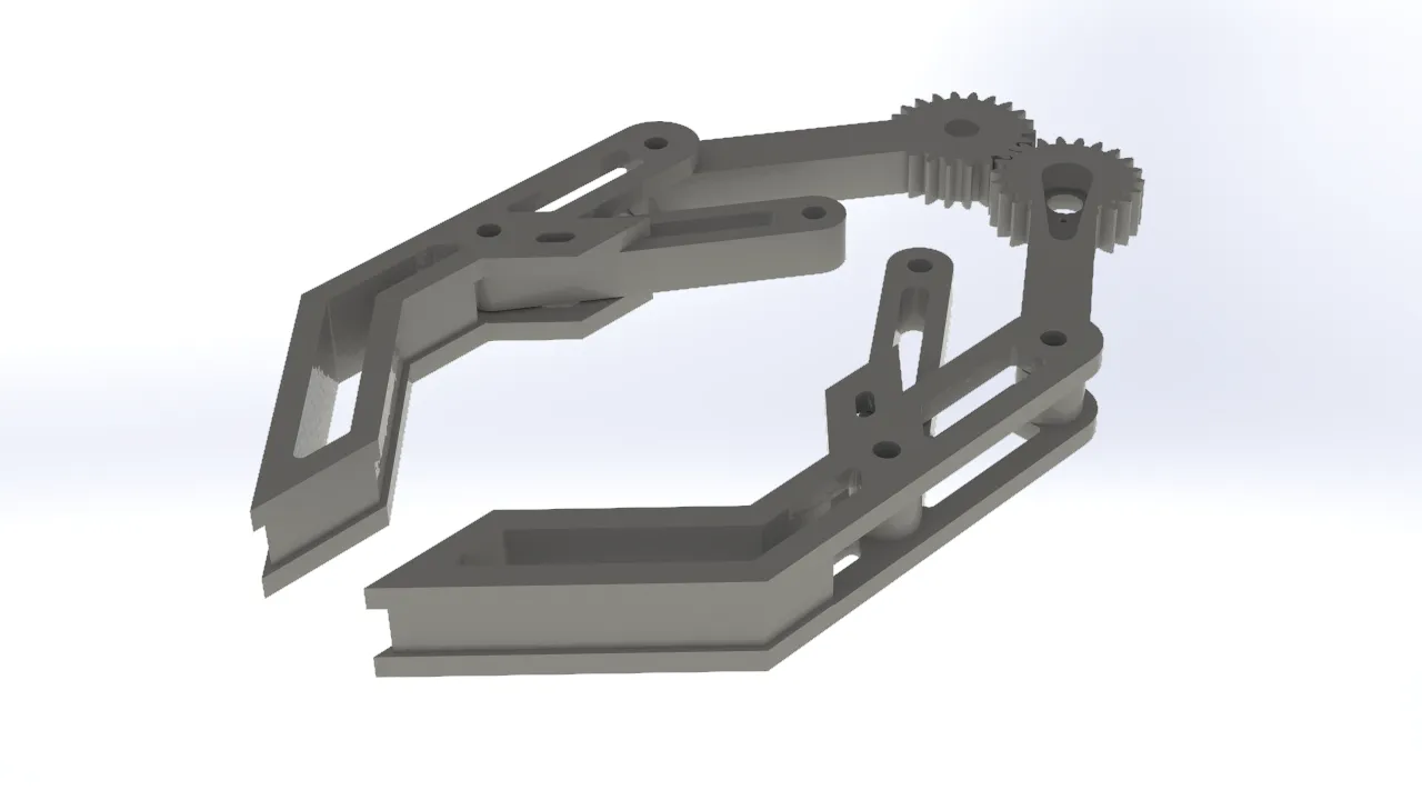
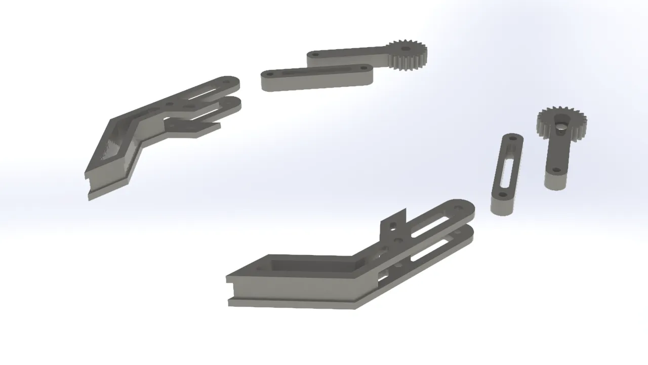
Gripper
For the gripper, I opted for a simple and traditional design commonly seen in other robotic arms. It consisted of a two-gear mechanism, with one gear connected to a servo. Each gear was linked to one side of the gripper jaw, so that when the servo-driven gear rotated, the gripper opened or closed depending on the direction of rotation. I added additional support beams to keep the gripper aligned and prevent it from tilting when opening or closing, which was important for achieving a more secure and consistent grip on objects.
Cable Organization
To clearly visualize the integration of the cables into the project, I created graphical representations of their distribution and connections.
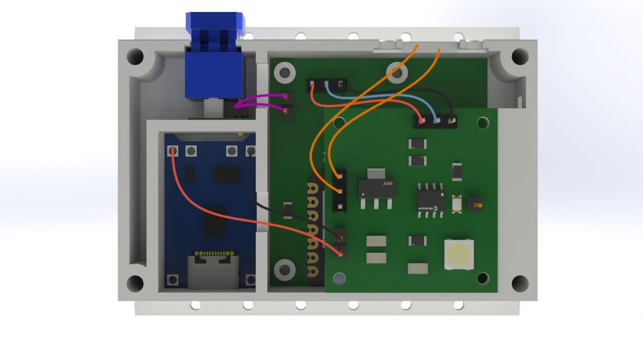
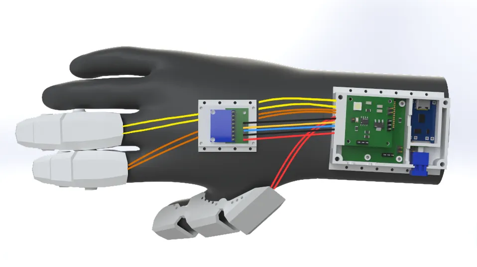
For the cable connections, I chose to use female pin connectors soldered to male pins to ensure a solid and reliable connection. Personally, I would have preferred to use a different type of terminal, but the limited space in the design did not allow for it. As a result, I opted for this solution which, while not ideal, was functional and well-suited to the project's requirements.
In this case, I chose to use Dupont-type connectors for the logic connections between the arm's electronics. This decision
was made because the space inside the arm's base was more generous than in the glove, which meant there were no constraints
preventing the use of this type of connector. While Dupont connectors were not as robust as pin connectors, they offered
the practical advantage of being much easier to connect and disconnect.
Printing Process
For my 3D prints, I used my Creality Ender 3 V3 SE printer with the following parameters:
3D Printing Parameters for Glove
- Quality: Layer Height of 0.2mm
- Infill: 10% Cubic
- Print Speed: 180 mm/s
- Wall Line Count: 4 lines
- Plate Adhesion: None
- Support: Tree Support
3D Printing Parameters for Robot Arm
- Quality: Layer Height of 0.2mm
- Infill: 5% Cubic
- Print Speed: 180 mm/s
- Wall Line Count: 2 lines
- Plate Adhesion: None
- Support: Tree Support
As the printing material, I used 1.75mm diameter PLA from the Creality brand. I used a printing temperature of 215°C for the first layer and 210°C for the remaining layers, with a bed temperature of 65°C for the first layer and 60°C for the rest.
Electronic Production
To produce my PCBs, I followed the same steps I took during my Electronic Production week.
Electronic Production Week 8
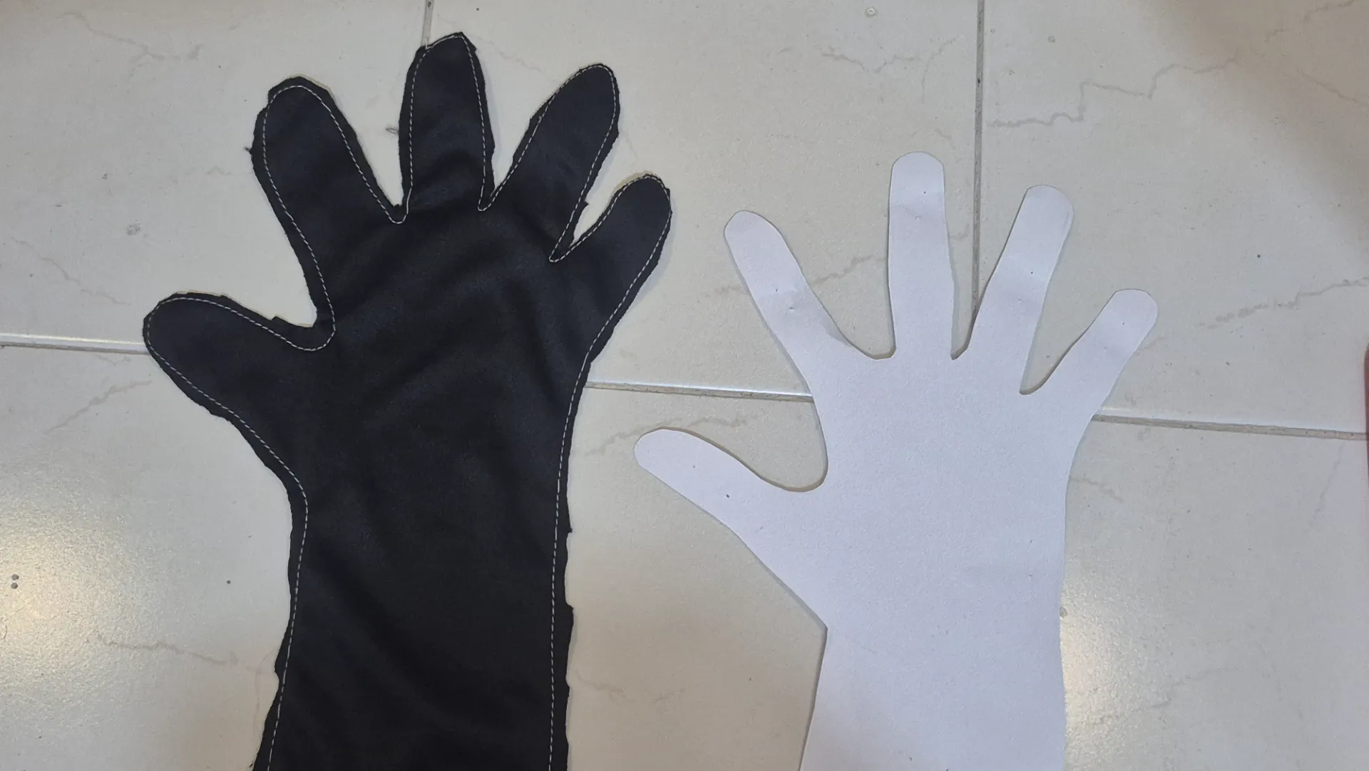
Glove Textile Production
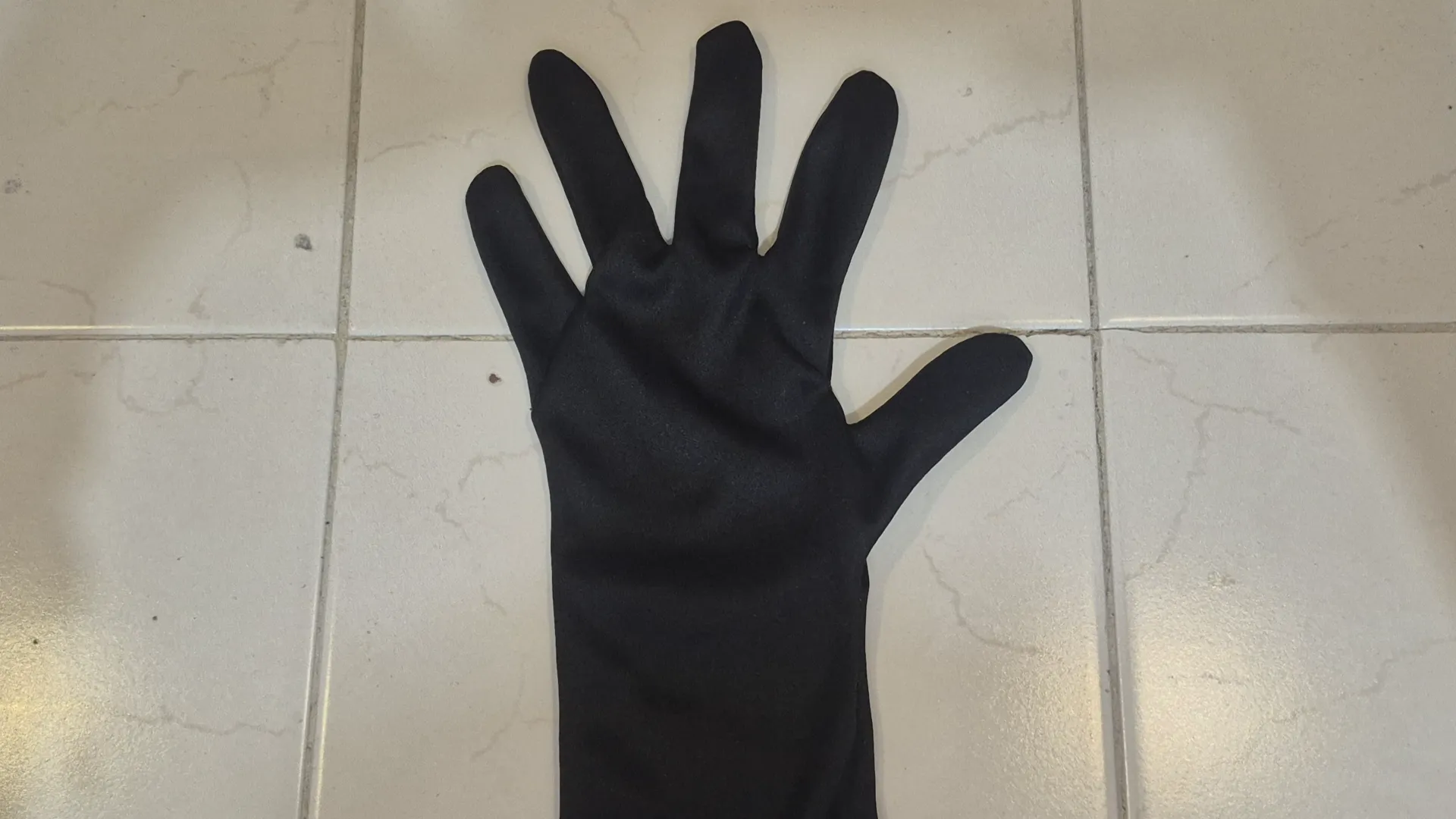
For the glove's fabric, I decided to use lycra, an elastic and breathable fabric that was comfortable to wear.
I made the glove using my own hand as a reference. I drew the pattern on paper, cut it out, and with the help of some chalk, I traced it onto the fabric. Then, I cut the fabric and sewed the parts together to form the glove.
Assembly and Integration
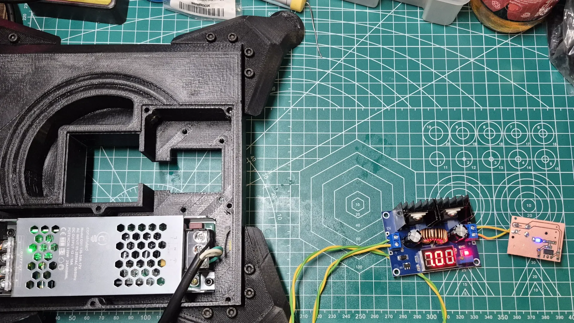
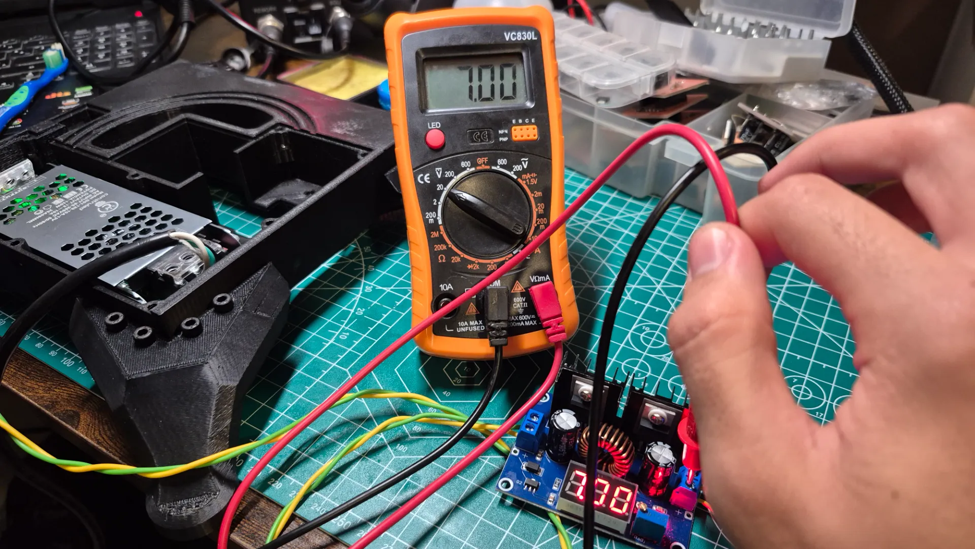
Power Test
For the project's assembly, I first focused on testing that all parts worked correctly before integrating them. Initially, I tested the power section of the robotic arm, making sure that the power supplies I acquired to run the system functioned properly.
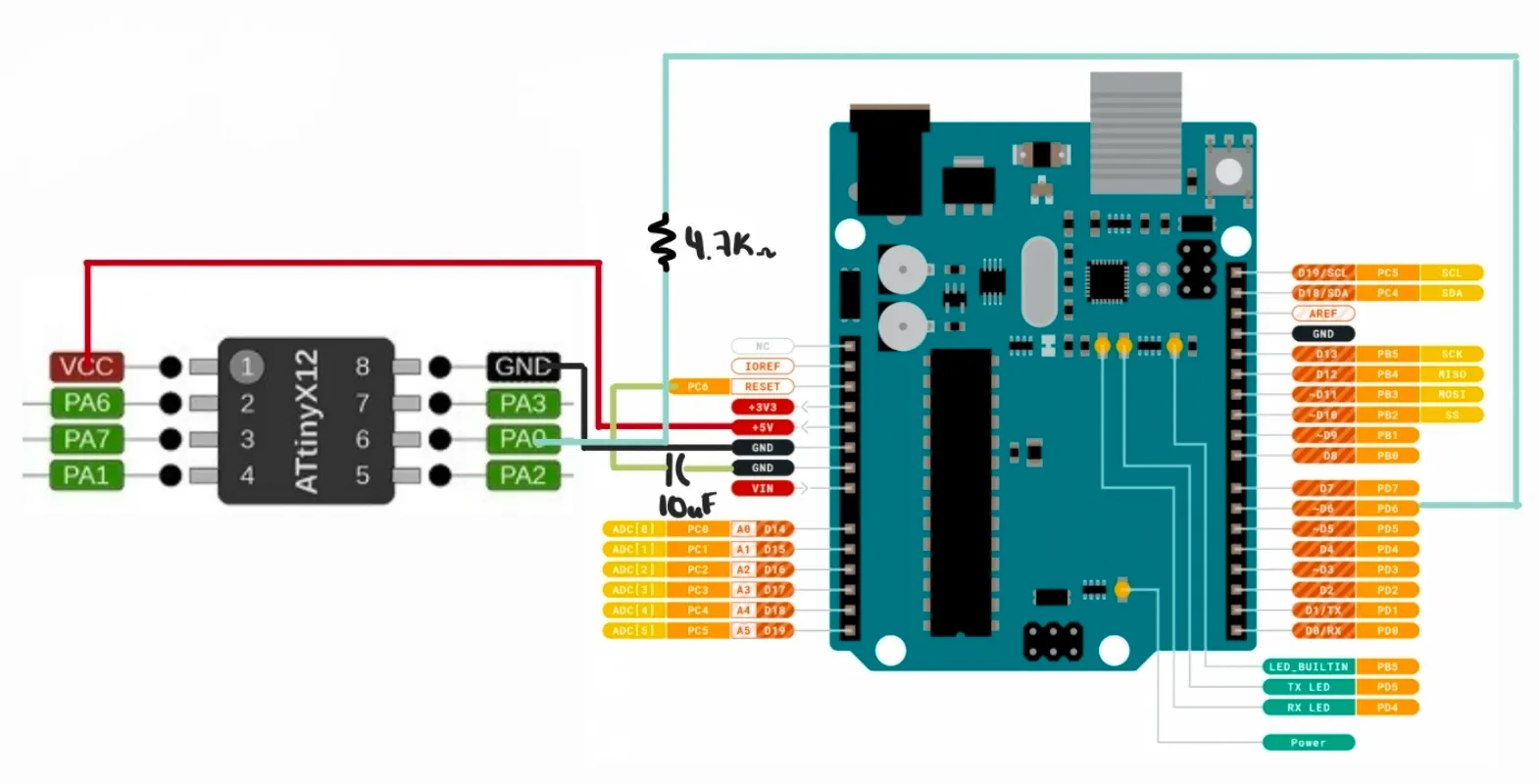
ATtiny412 Test
Afterward, I tested programming the ATtiny412 with the NeoPixel LED to indicate the glove's battery level. To do this, I used an Arduino UNO, connecting the ATtiny and the Arduino UNO as follows:
To make the Arduino UNO work as a programmer, I downloaded a jtag2updi zip folder and opened it in the Arduino IDE.
jtag2updi on GitHub
I uploaded that file to the Arduino UNO, and in File > Preferences, in the Additional Boards Manager URLs section, I pasted the following link: http://drazzy.com/package_drazzy.com_index.json
In Tools > Board > Boards Manager, I searched for “megaTinyCore” and installed it. Later, in Tools > Programmer, I selected jtag2updi (megaTinyCore). Then, in Tools > Board, I selected ATtiny412/402/212/102, and in the next menu, I selected ATtiny412. Finally, to program it, I went to Sketch > Upload Using Programmer.
The test I ran was to make the NeoPixel LED light up in RGB.
#include <Arduino.h>
#include <Adafruit_NeoPixel.h>

#define NEO_PIN     3
#define NUM_PIXELS  1
#define BRIGHTNESS  150
#define HUE_STEP    200
#define FRAME_DELAY 10

Adafruit_NeoPixel pixel(NUM_PIXELS, NEO_PIN, NEO_GRB + NEO_KHZ800);

void setup() {
  pixel.begin();
  pixel.setBrightness(BRIGHTNESS);
  pixel.clear();
  pixel.show();
}

void loop() {
  for (uint16_t hue = 0; hue < 65536; hue += HUE_STEP) {

    uint32_t color = pixel.gamma32(pixel.ColorHSV(hue));

    pixel.setPixelColor(0, color);
    pixel.show();
    delay(FRAME_DELAY);
  }
}
Libraries and Definitions
#include <Adafruit_NeoPixel.h>: Library that handles the communication protocol of the NeoPixel LED (single-wire digital signal at 800KHz).NEO_PIN 3: GPIO pin where the data signal is sent to the LED.BRIGHTNESS 150: Global brightness applied to all colors (0-255).HUE_STEP 200: Hue increment per frame. It determines how fast the color changes.FRAME_DELAY 10: Pause in milliseconds between each LED update.
Setup
pixel.begin(): Initialized the data pin and prepared the internal NeoPixel driver.pixel.setBrightness(150): Scaled all RGB values before sending them without altering the calculated color.pixel.clear()+pixel.show(): Turned off the LED at startup by sending zeros to all RGB channels.
Auxiliary Function: Hue to RGB Color
ColorHSV(hue): Translated a hue value from 0-65535 into a 32-bit RGB color, cycling through the entire color wheel: red to green to blue to red.gamma32(color): Corrected the human eye's perception curve so the transition between colors looked visually uniform.
Main Loop
- For loop (0 to 65535, step 200): Cycled through 328 frames at 10ms each, resulting in a complete 3.3-second cycle.
pixel.setPixelColor(0, color): Wrote the color to the internal buffer without sending it yet.pixel.show(): Sent the buffer to the LED via the 800KHz signal, updating the visible color.
Sensors Test
I performed the test for my sensors during Inputs Devices week.
Inputs Devices Week 9
Servos and Nema Test
For the servos test, I relied on the interface I created during Interface and Application Programming week. With these tests, I was able to get an idea of the torque generated by my servos and the range of motion they offered. Thanks to these tests, I realized that the servos labeled 25kg had more torque than the 35kg ones. This is evident in how the joint flexes when the arm is completely horizontal. That's why I decided to place the 25kg servo in the shoulder.
Interface and Application Programming Week 14
Communication Test
The communication I used in the project was ESP-NOW, based on my Networking and Communications week.
Networking and Communications Week 11
Troubleshooting & Design Modification
During the testing process, an issue arose with the power supply of the XIAO ESP32s. It seemed that the AMS1117 regulator did not provide the necessary current to power the microcontrollers while ESP-NOW was in use, since this communication generated current spikes of approximately 200 mA, causing them to restart constantly. To solve this, I placed a 10uF decoupling capacitor at the voltage input of the robotic arm's brain and the glove; this helped stabilize the voltage and prevent the drops that caused the reboots. However, this was not enough. Therefore, for the glove, I had to lower the ESP-NOW transmission power to reduce the current spikes to approximately 100 mA. On the arm's side, I had to lower the servos' power supply voltage from 7.6V to 5V (which was still within their working range, although they would generate less torque) and connected the microcontroller's power supply to that line. This finally solved the problem and allowed stable communication between the glove and the robotic arm.
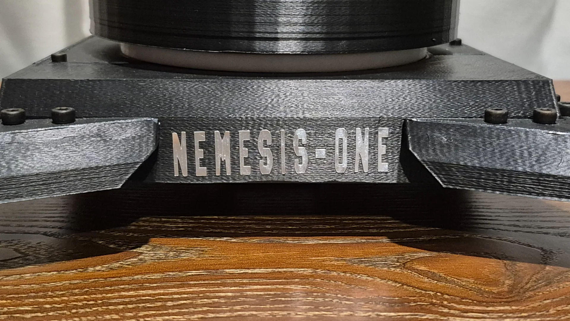
Stiker
To give the robot arm some style, I decided to add its name as a sticker to the base. For this, I used silver vinyl and followed the same process I used for Computer Controlled Cutting week.
Computer Controlled Cutting Week 3
Final Assembly
With the tests completed, I was able to assemble both the robotic arm and the glove.
To improve functionality and aesthetics, I organized the servomotor cables using a spiral cable sleeve. Loose cables looked messy and risked tangling or wearing out from the robotic arm's movements. Wrapping them securely reinforced the connections and gave the project a much cleaner, professional look.
Interface
For the system interface, I was inspired by the one I created during the Interface and Application Programming week; I simply removed the input section and added two sliders to control the arm's limbs and two buttons to open and close the gripper.
Interface and Application Programming Week 14

Programming
The project relied on 3 codes that made the system work.
Battery Level
The code to monitor the battery level used a voltage divider to reduce the battery voltage to a safe range for the microcontroller's ADC. With the NeoPixel LED, the battery's charge level was indicated using colors: green for a full charge, yellow for medium charge, solid red for low charge, and blinking red for a critical level.
#include <Arduino.h>
#include <Adafruit_NeoPixel.h>

#define PIN_NEOPIXEL   PIN_PA3
#define BAT_PIN        PIN_PA7
#define NUM_PIXELS     1

#define R1   100
#define R2   360

#define ADC_REF_MV   3300

#define V_GREEN    3800
#define V_YELLOW   3600
#define V_RED      3450

#define BRIGHTNESS     120
#define READ_EVERY_MS  2000
#define BLINK_MS       350

Adafruit_NeoPixel led(NUM_PIXELS, PIN_NEOPIXEL, NEO_GRB + NEO_KHZ800);

uint32_t lastRead  = 0;
uint32_t lastBlink = 0;
bool     blinkOn   = true;
uint16_t vbat_mV   = 4200;

uint16_t leerBateriaMv();

void setup() {
  led.begin();
  led.setBrightness(BRIGHTNESS);
  led.show();
  analogReference(VDD);
  analogSampleDuration(16);
  vbat_mV = leerBateriaMv();
}

void loop() {
  uint32_t ahora = millis();

  if (ahora - lastRead >= READ_EVERY_MS) {
    lastRead = ahora;
    vbat_mV = leerBateriaMv();
  }

  if (vbat_mV >= V_GREEN) {
    led.setPixelColor(0, led.Color(0, 255, 0));
    led.show();
  }
  else if (vbat_mV >= V_YELLOW) {
    led.setPixelColor(0, led.Color(255, 180, 0));
    led.show();
  }
  else if (vbat_mV >= V_RED) {
    led.setPixelColor(0, led.Color(255, 0, 0));
    led.show();
  }
  else {
    if (ahora - lastBlink >= BLINK_MS) {
      lastBlink = ahora;
      blinkOn = !blinkOn;
      led.setPixelColor(0, blinkOn ? led.Color(255, 0, 0) : 0);
      led.show();
    }
  }

  delay(20);
}

uint16_t leerBateriaMv() {
  analogRead(BAT_PIN);
  uint16_t suma = 0;
  for (uint8_t i = 0; i < 8; i++) {
    suma += analogRead(BAT_PIN);
    delay(2);
  }
  uint16_t raw   = suma / 8;
  uint32_t vnode = (uint32_t)raw * ADC_REF_MV / 1023;
  uint32_t vbat  = vnode * (R1 + R2) / R2;
  return (uint16_t)vbat;
}
Libraries and Definitions
#include <Adafruit_NeoPixel.h>: Library that handled the NeoPixel LED communication protocol.PIN_PA3: NeoPixel data pin.PIN_PA7: Analog pin connected to the voltage divider node.R1 = 100, R2 = 360: Values in kΩ of the resistive divider. With this proportion, the maximum 4.2V of the LiPo battery dropped to 3.28V at the node, falling right within the ADC range.ADC_REF_MV 3300: ADC reference voltage in millivolts (VDD = 3.3V).
Battery Thresholds
V_GREEN 3800: Above 3.80V, the LED turned green, meaning the battery was full.V_YELLOW 3600: Above 3.60V, the LED turned yellow, indicating half charge.V_RED 3450: Above 3.45V, the LED turned solid red, indicating 20% capacity.- Below 3.45V, the LED blinked red, indicating a critical level.
Setup
led.begin()andled.show(): Initialized the LED and turned it off at startup.analogReference(VDD): Set VDD (3.3V) as the ADC reference, which was required in megaTinyCore for accurate readings.analogSampleDuration(16): Increased the ADC sampling time. This was necessary because the 100kΩ/360kΩ divider had high impedance, and the ADC needed more time to stabilize before reading.
Auxiliary Function: leerBateriaMv()
- Discarded reading: The first call to
analogRead()was ignored to stabilize the internal ADC multiplexer before taking real readings. - 8-reading average: Reduced ADC noise by accumulating 8 samples and dividing by 8.
- Conversion to millivolts: Used
uint32_tfor intermediate arithmetic to prevent overflow, sinceraw x 3300exceeded the limit of a 16-bit integer.vnode: Voltage at the divider node in mV.vbat: Actual battery voltage, reconstructed by applying the inverse proportion of the divider:vbat = vnode x (R1 + R2) / R2.
Main Loop
- Periodic reading: The voltage was measured every 2 seconds using
millis()to avoid blocking the program while the LED blinked. - Green, yellow, and solid red: The color was updated directly with
led.setPixelColor()andled.show()depending on the corresponding threshold. - Critical blinking: When the voltage dropped below
V_RED, the LED alternated between red and off every 350ms usingmillis(), avoiding the use ofdelay()so the periodic battery reading wouldn't be interrupted. delay(20): A minimum pause at the end of the loop to stabilize the cycle without affecting the blinking response.
Transmitter Glove
The glove's code was responsible for collecting the sensor data, running it through filters to minimize noise, and sending the data to the receiver.
#include <Arduino.h>
#include <Wire.h>
#include <Adafruit_MPU6050.h>
#include <Adafruit_Sensor.h>
#include <WiFi.h>
#include <esp_now.h>
#include "driver/gpio.h"

#define Flex_1_Pin  2
#define Flex_2_Pin  3
#define Flex_3_Pin  4
#define Button_Pin  GPIO_NUM_8

#define FLEX_1_MIN 1000
#define FLEX_1_MAX 1900
#define FLEX_2_MIN 650
#define FLEX_2_MAX 1800
#define FLEX_3_MIN 350
#define FLEX_3_MAX 1900

#define NUM_SAMPLES   9
#define MIN_VALID     200
#define SMOOTH_FACTOR 0.3

#define ALPHA       0.98
#define CALIB_COUNT 500

#define DEBOUNCE_MS 250

uint8_t Receiver_Address[] = {0x58, 0xE6, 0xC5, 0x10, 0x43, 0xCC};

typedef struct Struct_Message {
  int Flex1;
  int Flex2;
  int Flex3;
  int Pitch;
  int Roll;
  int Yaw;
} Struct_Message;

Struct_Message Out_Going_Data;

Adafruit_MPU6050 mpu;

float EMA_Value[3]  = {FLEX_1_MIN, FLEX_2_MIN, FLEX_3_MIN};
int   Last_Valid[3] = {FLEX_1_MIN, FLEX_2_MIN, FLEX_3_MIN};

float Pitch = 0, Roll = 0, Yaw = 0;
float Gyro_Bias_X = 0, Gyro_Bias_Y = 0, Gyro_Bias_Z = 0;
unsigned long Last_Time = 0;
unsigned long Sample_Count = 0;

volatile bool Button_Flag        = false;
unsigned long Last_Debounce      = 0;
int           Button_Press_Count = 0;
bool          Paused             = false;

float Last_Angle1 = 0, Last_Angle2 = 0, Last_Angle3 = 0;
float Last_Pitch  = 0, Last_Roll   = 0, Last_Yaw    = 0;

void Sort_Array(int *arr, int n) {
  for (int i = 0; i < n - 1; i++)
    for (int j = 0; j < n - i - 1; j++)
      if (arr[j] > arr[j + 1]) {
        int tmp = arr[j]; arr[j] = arr[j + 1]; arr[j + 1] = tmp;
      }
}

int Median_Filter(int pin, int index) {
  int samples[NUM_SAMPLES];
  int valid = 0;
  for (int i = 0; i < NUM_SAMPLES; i++) {
    int val = analogRead(pin);
    delay(2);
    if (val >= MIN_VALID) samples[valid++] = val;
  }
  if (valid == 0) return Last_Valid[index];
  Sort_Array(samples, valid);
  Last_Valid[index] = samples[valid / 2];
  return Last_Valid[index];
}

float EMA_Filter(int median, int index) {
  EMA_Value[index] = EMA_Value[index] * (1 - SMOOTH_FACTOR) + median * SMOOTH_FACTOR;
  return EMA_Value[index];
}

float Read_Flex_Filtered(int pin, int index) {
  return EMA_Filter(Median_Filter(pin, index), index);
}

float To_Angle(float raw, int raw_min, int raw_max) {
  float n = (raw - raw_min) / (float)(raw_max - raw_min);
  n = constrain(n, 0.0, 1.0);
  return n * 135.0;
}

void Calibrate_Gyro() {
  Serial.println(">> Calibrando giroscopio, NO MUEVAS el sensor...");
  float sx = 0, sy = 0, sz = 0;
  sensors_event_t a, g, t;
  for (int i = 0; i < CALIB_COUNT; i++) {
    mpu.getEvent(&a, &g, &t);
    sx += g.gyro.x;
    sy += g.gyro.y;
    sz += g.gyro.z;
    delay(2);
  }
  Gyro_Bias_X = sx / CALIB_COUNT;
  Gyro_Bias_Y = sy / CALIB_COUNT;
  Gyro_Bias_Z = sz / CALIB_COUNT;
  Serial.printf("Bias -> X:%.4f  Y:%.4f  Z:%.4f\n",
                Gyro_Bias_X, Gyro_Bias_Y, Gyro_Bias_Z);
}

void Update_Orientation() {
  sensors_event_t accel, gyro, temp;
  mpu.getEvent(&accel, &gyro, &temp);

  unsigned long now = micros();
  float dt = (now - Last_Time) / 1000000.0;
  Last_Time = now;

  float gx = (gyro.gyro.x - Gyro_Bias_X) * 180.0 / PI;
  float gy = (gyro.gyro.y - Gyro_Bias_Y) * 180.0 / PI;
  float gz = (gyro.gyro.z - Gyro_Bias_Z) * 180.0 / PI;

  float acc_pitch = atan2(accel.acceleration.y,
  sqrt(accel.acceleration.x * accel.acceleration.x +
  accel.acceleration.z * accel.acceleration.z)) * 180.0 / PI;
  float acc_roll  = atan2(-accel.acceleration.x,
  accel.acceleration.z) * 180.0 / PI;

  Pitch = ALPHA * (Pitch + gx * dt) + (1 - ALPHA) * acc_pitch;
  Roll  = ALPHA * (Roll  + gy * dt) + (1 - ALPHA) * acc_roll;
  Yaw  += gz * dt;
}

void IRAM_ATTR Button_ISR() {
  unsigned long now = millis();
  if (now - Last_Debounce > DEBOUNCE_MS) {
    Button_Flag   = true;
    Last_Debounce = now;
  }
}

void Setup_Button() {
  gpio_config_t config = {
    .pin_bit_mask = (1ULL << Button_Pin),
    .mode         = GPIO_MODE_INPUT,
    .pull_up_en   = GPIO_PULLUP_DISABLE,
    .pull_down_en = GPIO_PULLDOWN_ENABLE,
    .intr_type    = GPIO_INTR_DISABLE
  };
  gpio_config(&config);

  attachInterrupt(8, Button_ISR, RISING);
}

void Check_Button() {
  if (Button_Flag) {
    Button_Flag = false;
    Paused = !Paused;
    Button_Press_Count++;

    if (Paused) {
      Last_Angle1 = To_Angle(EMA_Value[0], FLEX_1_MIN, FLEX_1_MAX);
      Last_Angle2 = To_Angle(EMA_Value[1], FLEX_2_MIN, FLEX_2_MAX);
      Last_Angle3 = To_Angle(EMA_Value[2], FLEX_3_MIN, FLEX_3_MAX);
      Last_Pitch  = Pitch;
      Last_Roll   = Roll;
      Last_Yaw    = Yaw;
      Serial.println("\n  [[ PAUSADO — Servos congelados ]]");
    } else {
      Serial.println("\n  [[ REANUDADO ]]");
    }
  }
}

void On_Data_Sent(const wifi_tx_info_t* info, esp_now_send_status_t status) {
}

void Setup_ESPNOW() {
  WiFi.mode(WIFI_STA);

  WiFi.setTxPower(WIFI_POWER_2dBm);

  if (esp_now_init() != ESP_OK) {
    Serial.println("Error al iniciar ESP-NOW");
    return;
  }

  esp_now_register_send_cb(On_Data_Sent);

  esp_now_peer_info_t peerInfo = {};
  memcpy(peerInfo.peer_addr, Receiver_Address, 6);
  peerInfo.channel = 0;
  peerInfo.encrypt = false;

  if (esp_now_add_peer(&peerInfo) != ESP_OK) {
    Serial.println("Error al agregar el receptor");
    return;
  }

  Serial.println("ESP-NOW listo.");
}

void Send_Data() {
  Out_Going_Data.Flex1 = (int)round(Last_Angle1);
  Out_Going_Data.Flex2 = (int)round(Last_Angle2);
  Out_Going_Data.Flex3 = (int)round(Last_Angle3);
  Out_Going_Data.Pitch = (int)round(Last_Pitch);
  Out_Going_Data.Roll  = (int)round(Last_Roll);
  Out_Going_Data.Yaw   = (int)round(Last_Yaw);

  esp_now_send(Receiver_Address, (uint8_t *) &Out_Going_Data,
               sizeof(Out_Going_Data));
}

void Print_Data(float a1, float a2, float a3,
                float pitch, float roll, float yaw) {
  Sample_Count++;
  String estado = Paused ? "[ PAUSADO ]" : "[ ACTIVO  ]";

  Serial.printf("\n--- Muestra #%lu | %lu ms | %s | Boton: %dx ---\n",
                Sample_Count, millis(), estado.c_str(), Button_Press_Count);

  Serial.println("  Flex (angulo):");
  Serial.printf("    Sensor 1: %.1f°\n", a1);
  Serial.printf("    Sensor 2: %.1f°\n", a2);
  Serial.printf("    Sensor 3: %.1f°\n", a3);

  Serial.println("  Orientacion (grados):");
  Serial.printf("    Pitch: %+.1f°\n", pitch);
  Serial.printf("    Roll : %+.1f°\n", roll);
  Serial.printf("    Yaw  : %+.1f°\n", yaw);
}

void setup() {
  Serial.begin(115200);
  delay(1000);

  Setup_Button();
  Setup_ESPNOW();

  Wire.begin();

  if (!mpu.begin()) {
    Serial.println("ERROR: MPU6050 no detectado.");
    while (1) delay(10);
  }

  mpu.setGyroRange(MPU6050_RANGE_500_DEG);
  mpu.setAccelerometerRange(MPU6050_RANGE_8_G);
  mpu.setFilterBandwidth(MPU6050_BAND_21_HZ);

  delay(100);
  Calibrate_Gyro();
  Last_Time = micros();
  Serial.println("Sistema listo. Presiona el boton para pausar/reanudar.");
}

void loop() {
  Check_Button();

  if (!Paused) {
    float raw1 = Read_Flex_Filtered(Flex_1_Pin, 0); delay(5);
    float raw2 = Read_Flex_Filtered(Flex_2_Pin, 1); delay(5);
    float raw3 = Read_Flex_Filtered(Flex_3_Pin, 2); delay(5);

    Last_Angle1 = To_Angle(raw1, FLEX_1_MIN, FLEX_1_MAX);
    Last_Angle2 = To_Angle(raw2, FLEX_2_MIN, FLEX_2_MAX);
    Last_Angle3 = To_Angle(raw3, FLEX_3_MIN, FLEX_3_MAX);

    Update_Orientation();
    Last_Pitch = Pitch;
    Last_Roll  = Roll;
    Last_Yaw   = Yaw;
  }

  Send_Data();

  Print_Data(Last_Angle1, Last_Angle2, Last_Angle3,
             Last_Pitch, Last_Roll, Last_Yaw);

  delay(50);
}
Libraries
#include <Wire.h>: Handled I2C communication with the MPU6050 sensor.#include <Adafruit_MPU6050.h>and#include <Adafruit_Sensor.h>: Adafruit libraries that abstracted the IMU reading and delivered the data in standard physical units (m/s² and rad/s).#include <WiFi.h>and#include <esp_now.h>: Enabled ESP-NOW communication over the Wi-Fi layer.#include "driver/gpio.h": Low-level ESP-IDF API, necessary for configuring the button pin, which was a strapping pin and didn't behave correctly with standard Arduino functions.
Pin Definitions
Flex_1_Pin 2,Flex_2_Pin 3,Flex_3_Pin 4: Analog GPIOs connected to each flex sensor.Button_Pin GPIO_NUM_8: Button pin. Thegpio_num_tconstant from the ESP-IDF was used instead of the simple number because GPIO 8 is a strapping pin on the ESP32-C3.
Flex Sensors Calibration
FLEX_X_MINandFLEX_X_MAX: Defined the raw reading range (ADC) of each sensor between an extended finger and a flexed finger. These values were determined experimentally and varied per sensor due to manufacturing and assembly differences.
Filtering Parameters
NUM_SAMPLES 9: Number of samples taken by the median filter for each reading.MIN_VALID 200: Minimum threshold to consider a sample valid. Readings below this were discarded as noise or ADC crosstalk.SMOOTH_FACTOR 0.3: Smoothing factor for the EMA filter. It determined how much weight each new reading had compared to the historical data (30% new, 70% accumulated).
IMU Parameters
ALPHA 0.98: Complementary filter coefficient. 98% of the angle came from the gyroscope's integration, and 2% from the accelerometer.CALIB_COUNT 500: Number of samples averaged to calculate the gyroscope's bias (resting drift) at startup.DEBOUNCE_MS 250: Button debounce time in milliseconds, ensuring a single press wasn't registered multiple times.
Data Structure and Addressing
Receiver_Address[]: Receiver's MAC address, to which the packets were sent. This had to match the MAC address the receiver printed at startup.Struct_Message: Defined the packet sent with six integers (Flex1-3, Pitch, Roll, Yaw). Its definition had to be identical in both the transmitter and receiver for proper deserialization.
Median Filter: Sort_Array() and Median_Filter()
Sort_Array(): Implemented a simple bubble sort, which was suitable given the small number of samples.Median_Filter(): Took 9 ADC readings, discarded invalid ones (belowMIN_VALID), sorted the valid ones, and returned the center value. The median was robust against spurious spikes: an isolated outlier wouldn't affect the result, unlike an average. If there were no valid readings, it returned the last known good value.
EMA Filter: EMA_Filter()
The exponential moving average filter smoothed the signal already processed by the median filter. Its formula was:
EMA = EMA x (1 - 0.3) + median x 0.3- This equated to keeping 70% of the previous value and adding 30% of the new reading, producing a smooth transition that eliminated residual jitter without introducing noticeable delay.
Read_Flex_Filtered()Chained both filters: first median, then EMA.
Angle Conversion: To_Angle()
- Normalized the raw reading within its calibrated range:
n = (raw - min) / (max - min), yielding a value between 0 and 1. constrain(n, 0.0, 1.0)Prevented readings outside the calibrated range from producing negative angles or exceeding the maximum.- Multiplied by 135.0 to map the result to the usable 0° to 135° travel range expected by the receiver's servos.
Gyroscope Calibration: Calibrate_Gyro()
- Averaged 500 gyroscope readings while the sensor remained still to measure its resting drift (bias) on each axis.
- This bias was later subtracted from each reading. Without this correction, the gyroscope would continuously accumulate error, causing the angles to drift even without movement.
Complementary Filter: Update_Orientation()
This function fused the gyroscope and accelerometer to obtain a stable orientation. Each sensor by itself was deficient: the gyroscope was precise in the short term but drifted over time, while the accelerometer was stable in the long term but noisy during movement.
- dt: Calculated the actual elapsed time using
micros(), which was necessary to correctly integrate the gyroscope's angular velocity. - Gyroscope conversion: Subtracted the bias and converted from rad/s to °/s by multiplying by
180/PI. - Accelerometer angles: Used
atan2()on the acceleration components to calculate pitch and roll based on gravity's direction. - Fusion:
Pitch = 0.98 x (Pitch + gyro x dt) + 0.02 x acc_pitch. The gyroscope term provided a quick response, and the accelerometer slowly corrected the drift. - Yaw: Was only integrated from the gyroscope (
Yaw += gz x dt). Without a magnetometer, there was no absolute reference to correct it, so it drifted over time—which was why the receiver used Pitch and not Yaw for the base.
Button Handling (Strapping Pin)
Button_ISR(): Interrupt routine marked withIRAM_ATTRso it ran from internal RAM (faster). It applied time-based debounce and only raised a flag, keeping the interrupt as brief as possible.Setup_Button(): Configured GPIO 8 using the low-levelgpio_config()withGPIO_PULLDOWN_ENABLE. This was necessary because GPIO 8 was a strapping pin on the ESP32-C3, and standard Arduino functions didn't properly configure its internal resistance. The interrupt was triggered on a rising edge (RISING).Check_Button(): Toggled the pause state when detecting the flag. When paused, it froze the last flex and orientation values so the receiver held its position; upon resuming, it picked up live readings again.
ESP-NOW Configuration: Setup_ESPNOW()
WiFi.mode(WIFI_STA): Set the Wi-Fi to station mode, required for ESP-NOW.WiFi.setTxPower(WIFI_POWER_2dBm): Deliberately reduced the transmission power. High power caused current spikes leading to battery voltage drops; lowering it stabilized the power supply at the expense of some range.- Registered the send callback and added the receiver as a peer with the defined MAC address, without encryption and on channel 0.
Sending and Monitoring
Send_Data(): Rounded floating values to integers, placed them in the structure, and transmitted them usingesp_now_send().Print_Data(): Printed the complete system state via serial (angles, orientation, sample number, pause state, and press count) for debugging purposes.
Setup
- Initialized the button and ESP-NOW, started the I2C bus, and verified the presence of the MPU6050; if it didn't respond, the program halted in an infinite loop.
- Configured the IMU ranges: gyroscope to ±500°/s, accelerometer to ±8g, and the internal low-pass filter to 21Hz.
- Executed the gyroscope calibration and logged the initial time to calculate
dt.
Main Loop
- Button:
Check_Button()checked at the beginning of each cycle if there was a pending pause change. - Active reading: If not paused, it read and filtered the three flex sensors, converted them to angles, and updated the IMU orientation.
- Continuous sending:
Send_Data()transmitted on every iteration, even during a pause, keeping the receiver fed with the latest frozen values. delay(50): Set the transmission frequency at approximately 20Hz, which was enough for fluid control without saturating the channel.
Receiver Arm
The robotic arm's code handled receiving data sent by the glove, processing it, and moving the corresponding servos and NEMA motor to replicate the glove's movements.
#include <Arduino.h>
#include <WiFi.h>
#include <esp_now.h>
#include <Preferences.h>

const int PINES[4]      = {17, 19, 20, 18};
const int ANGULO_MAX[4] = {270, 270, 270, 180};

const float SERVO_HOME[4] = {220, 135, 135, 90};
const int   SERVO_DIR[4]  = {1, -1, 1, 1};
const int   LIM_MIN[4]    = {0,   0,   0,   0};
const int   LIM_MAX[4]    = {270, 270, 270, 180};

#define ENGAGE_THRESHOLD 8.0

const int  FREQ      = 50;
const int  RES_BITS  = 16;
const long PERIODO   = 20000;
const long MAX_DUTY  = (1 << RES_BITS) - 1;
const int  PULSO_MIN    = 500;
const int  PULSO_MAX270 = 2500;
const int  PULSO_MAX180 = 2400;

#define STEP_PIN    16
#define DIR_PIN     23
#define FLT_PIN     22

#define STEPS_PER_REV   200
#define MICROSTEPPING   16
#define GEAR_RATIO      1.0

#define STEP_INTERVAL_US 75
#define STEP_PULSE_US    3

#define SERVO_SPEED     70.0
#define UPDATE_INTERVAL 20

const float STEPS_PER_DEGREE =
(STEPS_PER_REV * MICROSTEPPING * GEAR_RATIO) / 360.0;
const char* SERVO_NAMES[4] =
{"Roll (S1)", "Flex1 (S2)", "Flex2 (S3)", "Flex3 (S4)"};

float servo_zero[4]    = {220, 135, 135, 90};
float servo_current[4] = {220, 135, 135, 90};
float servo_target[4]  = {220, 135, 135, 90};
bool  servo_engaged[4] = {false, false, false, false};

long Stepper_Pos = 0;
long Stepper_Target = 0;
unsigned long Last_Step_Us = 0;

Preferences prefs;
bool Calibrating = false;
int  Cal_Index   = 0;

typedef struct Struct_Message {
  int Flex1, Flex2, Flex3, Pitch, Roll, Yaw;
} Struct_Message;

Struct_Message Incoming;
volatile bool New_Data = false;

long microsADuty(int us) {
  us = constrain(us, 500, 2500);
  return (long)us * MAX_DUTY / PERIODO;
}

int gradosAMicros(int idx, float grados) {
  int pulsoMax = (idx == 3) ? PULSO_MAX180 : PULSO_MAX270;
  grados = constrain(grados, 0, ANGULO_MAX[idx]);
  return map((long)(grados * 10), 0, (long)ANGULO_MAX[idx]
  * 10, PULSO_MIN, pulsoMax);
}

void escribirServo(int idx, float grados) {
  ledcWrite(PINES[idx], microsADuty(gradosAMicros(idx, grados)));
}

void Update_Servos() {
  static unsigned long last = 0;
  unsigned long now = millis();
  if (now - last < UPDATE_INTERVAL) return;
  float dt = (now - last) / 1000.0;
  last = now;
  float max_step = SERVO_SPEED * dt;

  for (int i = 0; i < 4; i++) {
    float diff = servo_target[i] - servo_current[i];
    if (fabs(diff) <= max_step) servo_current[i] = servo_target[i];
    else servo_current[i] += (diff > 0 ? max_step : -max_step);
    escribirServo(i, servo_current[i]);
  }
}

void Stepper_Setup() {
  pinMode(STEP_PIN, OUTPUT);
  pinMode(DIR_PIN, OUTPUT);
  pinMode(FLT_PIN, INPUT_PULLUP);

  digitalWrite(DIR_PIN, HIGH);
  digitalWrite(STEP_PIN, LOW);
  delay(100);
}

void Stepper_Update() {
  if (Stepper_Pos == Stepper_Target) return;
  unsigned long now = micros();
  if (now - Last_Step_Us < STEP_INTERVAL_US) return;
  Last_Step_Us = now;

  bool horario = (Stepper_Target > Stepper_Pos);
  digitalWrite(DIR_PIN, horario ? HIGH : LOW);
  delayMicroseconds(3);

  digitalWrite(STEP_PIN, HIGH);
  delayMicroseconds(STEP_PULSE_US);
  digitalWrite(STEP_PIN, LOW);

  Stepper_Pos += horario ? 1 : -1;
}

void Save_Calibration() {
  prefs.begin("arm", false);
  for (int i = 0; i < 4; i++)
    prefs.putFloat(("z" + String(i)).c_str(), servo_zero[i]);
  prefs.end();
}

void Load_Calibration() {
  prefs.begin("arm", true);
  for (int i = 0; i < 4; i++)
    servo_zero[i] = prefs.getFloat(("z" + String(i)).c_str(), servo_zero[i]);
  prefs.end();
}

void Print_Servo_Prompt() {
  Serial.printf("\n>> Calibrando %s (reposo). Comandos:\n", SERVO_NAMES[Cal_Index]);
  Serial.println("   numero / +N / -N   |   ok = guardar y siguiente");
}

void Print_Stepper_Prompt() {
  Serial.println("\n>> Calibrando BASE (NEMA). \
  +N / -N pasos  |  ok = fijar cero y terminar");
}

void Handle_Calibration(String cmd) {
  cmd.trim();

  if (Cal_Index < 4) {
    if (cmd == "ok") {
      servo_zero[Cal_Index] = servo_current[Cal_Index];
      Serial.printf("Reposo de %s = %.0f°\n", SERVO_NAMES[Cal_Index],
      servo_zero[Cal_Index]);
      Cal_Index++;
      (Cal_Index < 4) ? Print_Servo_Prompt() : Print_Stepper_Prompt();
      return;
    }
    float val = (cmd.startsWith("+") || cmd.startsWith("-"))
    ? servo_current[Cal_Index] + cmd.toFloat()
    : cmd.toFloat();
    val = constrain(val, LIM_MIN[Cal_Index], LIM_MAX[Cal_Index]);
    servo_current[Cal_Index] = val;
    servo_target[Cal_Index]  = val;
    escribirServo(Cal_Index, val);
    Serial.printf("%s -> %.0f°\n", SERVO_NAMES[Cal_Index], val);

  } else {
    if (cmd == "ok") {
      Stepper_Pos = 0;
      Stepper_Target = 0;
      Save_Calibration();
      Calibrating = false;
      for (int i = 0; i < 4; i++) servo_engaged[i] = false;
      Serial.println("Cero de la base fijado.");
      Serial.println("== Calibracion completa y guardada ==\n");
      return;
    }
    Stepper_Target = (cmd.startsWith("+") || cmd.startsWith("-"))
    ? Stepper_Target + cmd.toInt()
    : cmd.toInt();
    Serial.printf("Base -> %ld pasos\n", Stepper_Target);
  }
}

String Serial_Line() {
  static String buf = "";
  while (Serial.available()) {
    char c = Serial.read();
    if (c == '\n' || c == '\r') {
      if (buf.length() > 0) { String r = buf; buf = ""; return r; }
    } else buf += c;
  }
  return "";
}

void On_Data_Received(const esp_now_recv_info_t* info,
                      const uint8_t* data, int dataLen) {
  memcpy(&Incoming, data, sizeof(Incoming));
  New_Data = true;
}

void Apply_Targets() {
  int valores[4] = {Incoming.Roll, Incoming.Flex1, Incoming.Flex2, Incoming.Flex3};

  for (int i = 0; i < 4; i++) {
    float raw = constrain(servo_zero[i] + SERVO_DIR[i] * valores[i],
    LIM_MIN[i], LIM_MAX[i]);
    if (!servo_engaged[i] && fabs(raw - servo_current[i]) <= ENGAGE_THRESHOLD) {
      servo_engaged[i] = true;
      Serial.printf(">> %s enganchado\n", SERVO_NAMES[i]);
    }
    servo_target[i] = servo_engaged[i] ? raw : servo_zero[i];
  }

  float pitch = constrain((float)Incoming.Pitch, -90, 90);
  float base_deg = (pitch + 90.0) * (270.0 / 180.0);
  long nueva_meta = (long)(base_deg * STEPS_PER_DEGREE);

  if (abs(nueva_meta - Stepper_Target) > 2) {
    Stepper_Target = nueva_meta;
  }
}

void setup() {
  Serial.begin(115200);
  delay(500);

  for (int i = 0; i < 4; i++) ledcAttach(PINES[i], FREQ, RES_BITS);

  Stepper_Setup();

  Load_Calibration();
  for (int i = 0; i < 4; i++) {
    servo_current[i] = servo_zero[i];
    servo_target[i]  = servo_zero[i];
    servo_engaged[i] = false;
    escribirServo(i, servo_zero[i]);
  }

  WiFi.mode(WIFI_STA);
  Serial.print("MAC Address de este receptor: ");
  Serial.println(WiFi.macAddress());

  if (esp_now_init() != ESP_OK) {
    Serial.println("Error al iniciar ESP-NOW");
    return;
  }
  esp_now_register_recv_cb(On_Data_Received);

  Serial.println("Receptor listo (servos en reposo).");
  Serial.println("Escribe 'c' + Enter para calibrar.\n");
}

void loop() {
  String cmd = Serial_Line();
  if (cmd.length() > 0) {
    if (!Calibrating && cmd == "c") {
      Calibrating = true;
      Cal_Index = 0;
      Serial.println("\n=== MODO CALIBRACION ===");
      Print_Servo_Prompt();
    } else if (Calibrating) {
      Handle_Calibration(cmd);
    }
  }

  if (!Calibrating && New_Data) {
    New_Data = false;
    Apply_Targets();
  }

  if (!Calibrating) Update_Servos();

  if (digitalRead(FLT_PIN) == HIGH) {
    Stepper_Update();
  } else {
    static unsigned long last_fault = 0;
    if (millis() - last_fault > 2000) {
      Serial.println("!! FALLA en DRV8825 - revisa corriente/temperatura");
      last_fault = millis();
    }
  }
}
Libraries
#include <WiFi.h>: Necessary because ESP-NOW operated over the physical Wi-Fi layer of the ESP32, even though it didn't connect to any network.#include <esp_now.h>: Low-latency peer-to-peer communication protocol between two ESP32s without an intermediate router.#include <Preferences.h>: Saved the calibration in a non-volatile flash memory partition (NVS), so it survived reboots and power outages.
Servo Configuration
PINES[4] = {17, 19, 20, 18}: GPIOs for each servo.ANGULO_MAX[4] = {270, 270, 270, 180}: Maximum physical range for each servo. The first three were 270° and the fourth was 180°.SERVO_HOME[4] = {220, 135, 135, 90}: Factory resting position for each servo, generally the midpoint of its range.SERVO_DIR[4] = {1, -1, 1, 1}: Rotation direction of each servo. A value of-1inverted the direction via software, preventing the need to reverse wiring or mechanical assembly.LIM_MIN[4]andLIM_MAX[4]: Software limits that restricted the allowed travel of each servo, protecting the mechanical structure from collisions.ENGAGE_THRESHOLD 8.0: Degree threshold for the safety mechanism. The servo remained idle until the received value matched its current position within ±8°, avoiding sudden jumps when powering the system.
PWM Parameters (LEDC)
FREQ = 50: The servomotors required a 50Hz signal, equating to a 20ms period.RES_BITS = 16: 16-bit resolution for the PWM, yielding 65536 levels (0 to 65535) for very fine position control.PERIODO = 20000: The 20ms period expressed in microseconds.MAX_DUTY = (1 << 16) - 1 = 65535: Maximum duty cycle value, calculated via bit shifting.PULSO_MIN = 500,PULSO_MAX270 = 2500,PULSO_MAX180 = 2400: Pulse widths in microseconds defining the travel extremes. These didn't come from a physical equation but from the industry standard for servos: 0.5ms defined one extreme and 2.4–2.5ms the other.
Stepper Motor Parameters
STEP_PIN 16,DIR_PIN 23,FLT_PIN 22: Step, direction, and fault detection pins for the DRV8825.STEPS_PER_REV 200: Steps per revolution for a standard NEMA (1.8° per full step).MICROSTEPPING 16: Subdivision of each full step into 16 microsteps for smoother movement.STEP_INTERVAL_US 75: Minimum time between pulses in microseconds, which determined the maximum rotation speed.STEP_PULSE_US 3: Duration of the HIGH pulse on the STEP pin. The DRV8825 required a minimum pulse of a few microseconds to register a step.STEPS_PER_DEGREE = (200 x 16 x 1.0) / 360 = 8.89: Microsteps required to rotate the base one degree. This was the constant that converted angles into steps.
ESP-NOW Data Structure
Struct_Message: Defined the packet received from the transmitter with six integer fields:Flex1,Flex2,Flex3(glove sensors), andPitch,Roll,Yaw(from the IMU MPU6050). The structure had to be identical in both transmitter and receiver.volatile bool New_Data: The keywordvolatilewas mandatory because this flag was modified inside an interrupt (the callback) and read in the main loop; it instructed the compiler not to optimize it or store it in a register.
Angle to Signal Conversion: microsADuty()
This function translated a pulse width in microseconds to the 16-bit duty cycle value needed by ledcWrite(). Since the full 20ms period was divided into 65536 steps, a direct proportion was used:
- 0.5ms was 2.5% of the 20ms cycle →
500 x 65535 / 20000 ≈ 1638 - 2.5ms was 12.5% of the cycle →
2500 x 65535 / 20000 ≈ 8192 - The
constrain(us, 500, 2500)at the start ensured the pulse never went outside the servo's safe range.
Degrees to Microseconds Conversion: gradosAMicros()
- Selected the maximum pulse according to the servo: 2400µs for the 180° one (index 3) or 2500µs for the 270° ones.
- Used
map()ongrados x 10instead of directly on degrees. This trick multiplied by 10 before mapping to preserve one decimal point of resolution, sincemap()only worked with integers and would round off degree fractions.
Smoothed Movement: Update_Servos()
- It only ran every
UPDATE_INTERVAL = 20ms; if called earlier, it returned without doing anything. - Calculated
dt(actual elapsed time in seconds) and from that the maximum allowed displacement per frame:max_step = SERVO_SPEED x dt. With 70°/s and 20ms, it gave approximately 1.4° per update. - For each servo, if the difference from the target was less than
max_step, it jumped directly to the target; otherwise, it only advancedmax_stepin the right direction. This produced a controlled movement at a constant speed instead of instantaneous jumps.
Stepper Pulse Generation: Stepper_Update()
- Anti-oscillation safeguard:
if (Stepper_Pos == Stepper_Target) return;was critical—without this early return, the motor would continuously oscillate ±1 step around the target. - Non-blocking timing: Used
micros()to respect the minimum interval between steps without halting the rest of the program. Manual pulse generation was chosen over AccelStepper because the latter provided irregular timing when sharing the loop with ESP-NOW callbacks and servo updates. - Pulse sequence: set the direction according to the required way, waited 3µs for the driver to register the DIR change, generated the HIGH→LOW pulse on STEP, and incremented or decremented the accumulated position.
Persistent Calibration
Save_Calibration()/Load_Calibration(): Saved and retrieved the resting angle of each servo in the flash memory under the"arm"namespace, using keys"z0"to"z3".Handle_Calibration(cmd): State machine for the calibration. WhileCal_Index < 4, it calibrated servos; afterward, it calibrated the stepper's zero. It accepted an absolute number, a relative adjustment+N/-N, andokto confirm and advance to the next.Serial_Line(): Read the serial character by character in a non-blocking way, accumulating in a buffer until finding a line break, and then returning the complete line.
Target Application: Apply_Targets()
- Servos: Combined the calibration offset, the direction, and the received value:
servo_zero[i] + SERVO_DIR[i] x valores[i], bounded by the limits. The engagement mechanism only activated each servo when the incoming value approached its real position, keeping it idle until then. - Base (stepper): Mapped the IMU's Pitch to the base's rotation. The formula
(pitch + 90) x (270/180)converted the sensor's -90°...+90° range to the base's 0°...270° range, which was then translated into steps withSTEPS_PER_DEGREE. Pitch was used instead of Yaw because Yaw drifted without a magnetometer to correct it.
Setup
ledcAttach(PINES[i], FREQ, RES_BITS): Linked each servo GPIO to an ESP32 hardware timer configured at 50Hz and 16 bits.- Loaded the saved calibration, positioned the servos at rest, and initialized ESP-NOW in
WIFI_STAmode. - Printed the receiver's MAC address via serial, data required for the transmitter to know where to send the packets.
Main Loop
- Serial commands: Typing
cactivated the calibration mode; any subsequent line was delegated toHandle_Calibration(). - New data: When the callback flagged
New_Data, the targets were processed withApply_Targets(). The processing occurred in the loop and not in the interrupt to keep the callback as short as possible. - Continuous update:
Update_Servos()ran on every iteration to sustain the smooth movement. - Protected stepper: It only moved if
FLT_PINwas HIGH. If the DRV8825 reported a fault (pin LOW due to overtemperature or overcurrent), it printed a warning limited to once every 2 seconds to avoid saturating the serial monitor.
Final Results
Areas for Improvement
Currently, I'm using AMS1117 voltage regulators to power the microcontrollers. However, I've noticed that when the ESP-NOW communication protocol is activated, the microcontroller demands current spikes that the AMS1117 cannot efficiently supply. In the future, I plan to redesign this stage using higher-amperage buck converter regulators or LDOs to ensure completely stable wireless transmission.
The robotic arm uses a combination of servomotors with different power requirements (some operate at 6V, while larger ones require 7.4V). In this version, they are all powered through the same main line or cable. This creates a bottleneck that significantly limits the power and torque of the 7.4V servos. The improvement will involve separating the traces and creating independent power distribution lines so that each servo can operate at its maximum capacity.
From an aesthetic and functional standpoint, cable management can be significantly improved. The idea is to bundle and protect the cables using cable sleeves or spiral tubing for a much more professional and clean finish. Additionally, I noticed that when rotating the tonearm, the cables risk becoming tangled and strained; redesigning the routing so the cables pass through the center of the axis or using a slip ring would solve this problem.
While the hardware and 3D-printed parts of the glove work very well, the purely textile aspect has a lot of room for improvement. I'd like to refine the materials, stitching patterns, and fabric anchors to make the glove much more ergonomic, comfortable for the user during long sessions, and to keep the flex sensors in a firmer, more natural position.