System Integration
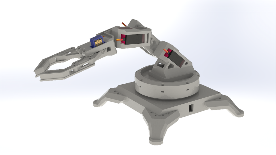
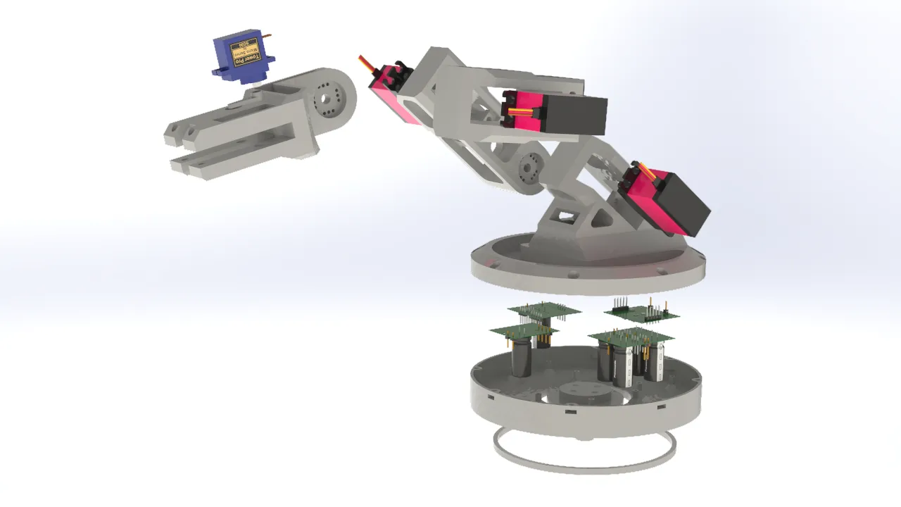
This week I focused on planning the integration of the final project system. In my case, the system consists of a controller glove and a robotic arm. I generated renders of the project parts and their exploded views to see in detail how the electronic components are integrated into the 3D design, as well as the location of the sensors and the distribution of the cables.
For this phase of the project, I used SolidWorks as the design software to create the necessary parts to assemble the controller glove and the robotic arm. The design focused mainly on the user's comfort when wearing the glove and the range of motion that could be achieved by the robotic arm.
Glove 3D Design
The design of the finger pieces was based on a medieval armor gauntlet. This structure provides the necessary mobility for manipulation tasks and keeps the sensors securely in place while in use. Personally, I also find this design quite visually appealing.
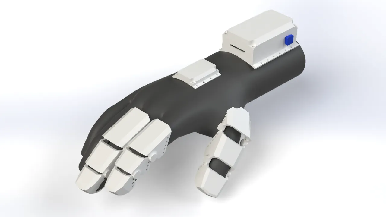
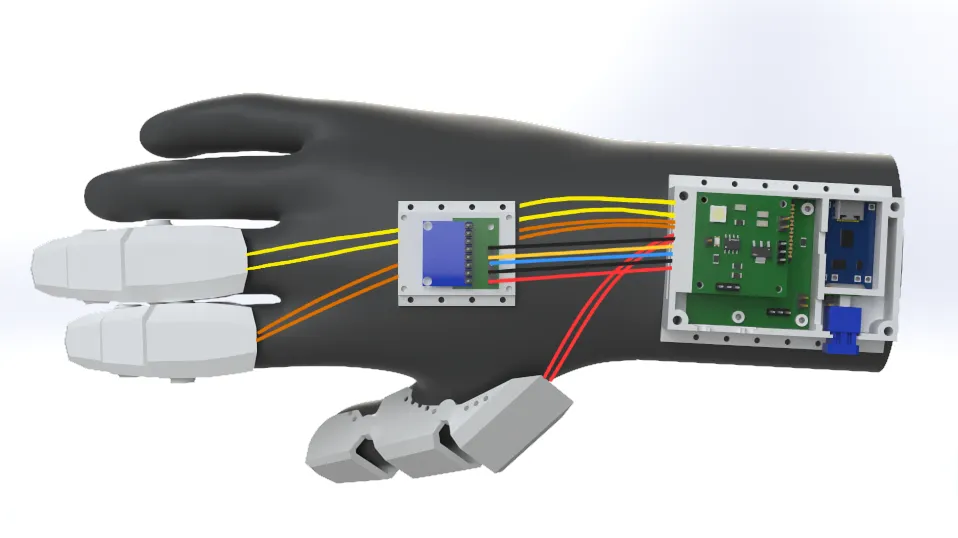
I also designed a couple of compartments for the glove's electronics. The wrist section will house the main PCBs, such as the XIAO ESP32-C3, along with the battery level indicator board and the charging circuit. The MPU6050 motion sensor will be placed on the back of the hand so it can accurately capture hand movements and transmit them to the robotic arm.
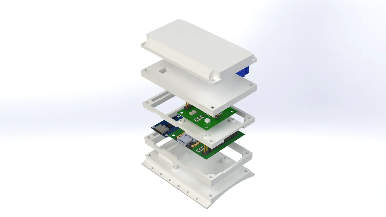
Bracelet
The bracelet accommodates the electronics in such a way that the microUSB port remains easily accessible for charging the battery and programming the microcontroller, without needing to take the bracelet apart. Additionally, I added a side button for various actions, like turning the glove on or switching control modes. The bracelet was designed with user comfort in mind, featuring an ergonomic shape that adapts to the wrist and holes to sew the piece directly onto the fabric of the glove.

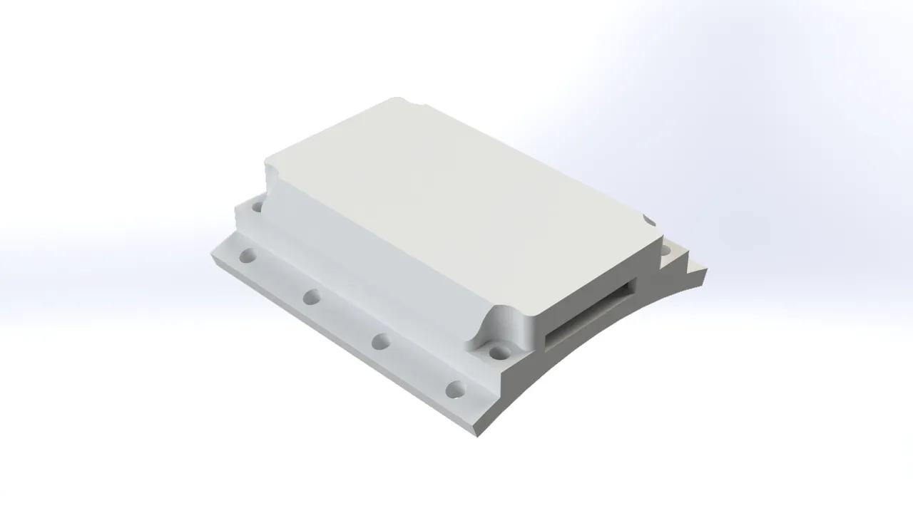
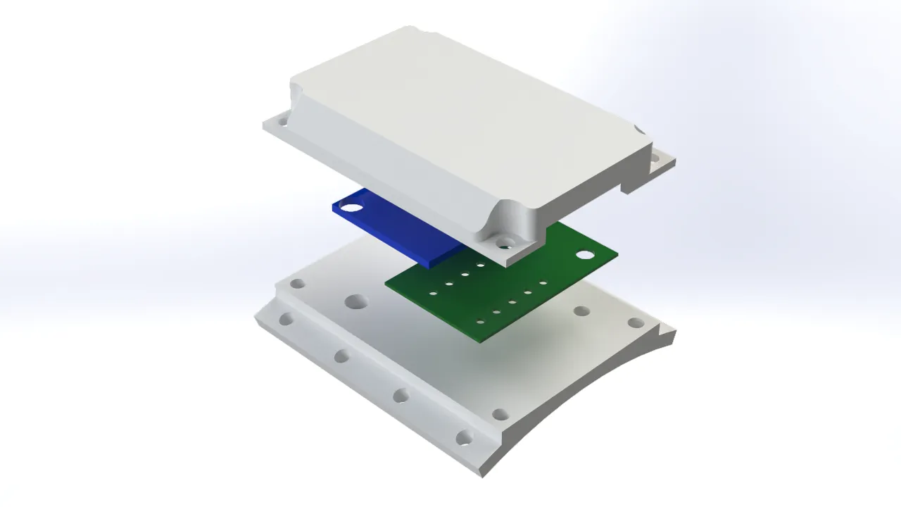
MPU6050 Case
Just like the bracelet, the MPU6050 case securely houses the electronics. It includes a hole for the power and communication wiring, and it was designed to be as compact as possible to minimize the weight on the back of the hand. The case features sewing holes to attach it to the glove, as well as screw holes to hold the motion sensor firmly in place and prevent it from shifting during use.
Fingers
The finger covers were designed so that the sensors stay perfectly in place when flexing and extending the fingers. Like the rest of the components, these covers have holes to be sewn onto the glove. I took into account the ergonomics of the fingers and their bending angles to shape these pieces properly.
Robotic Arm 3D Design
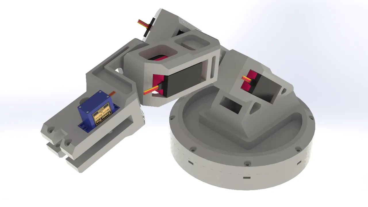
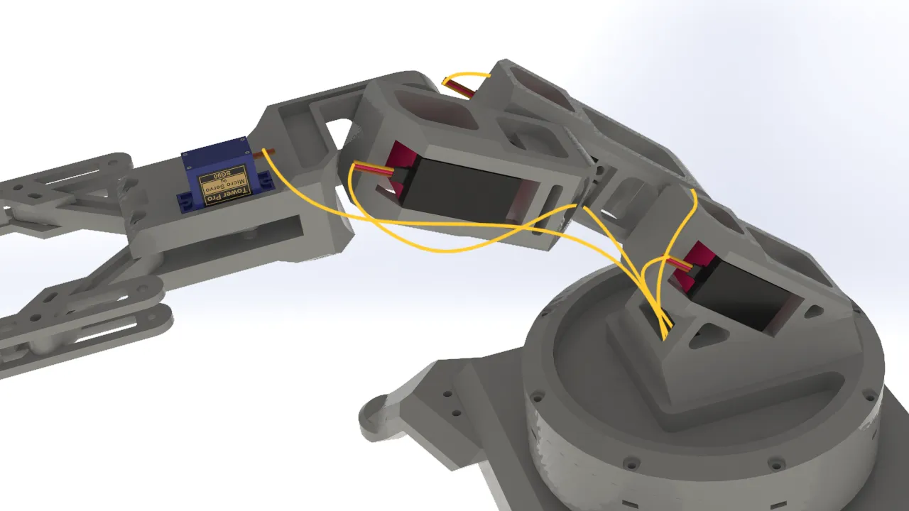
For the robotic arm design, I focused on the mobility of the joints, since the servos I used offered a 270° degree of freedom. I also prioritized keeping the parts as lightweight as possible in order to minimize the arm's total weight, preventing the servos from being strained by the torque required to move it. This approach also had the added benefit of maximizing the load the gripper could carry.
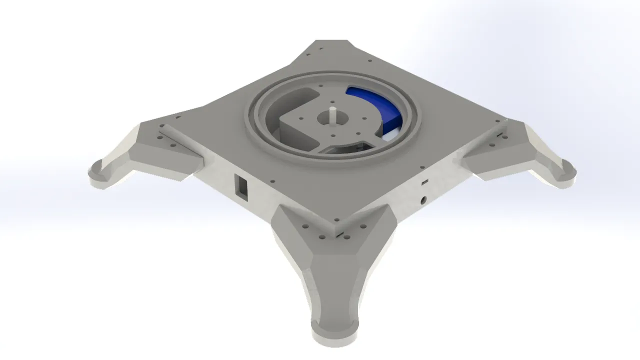
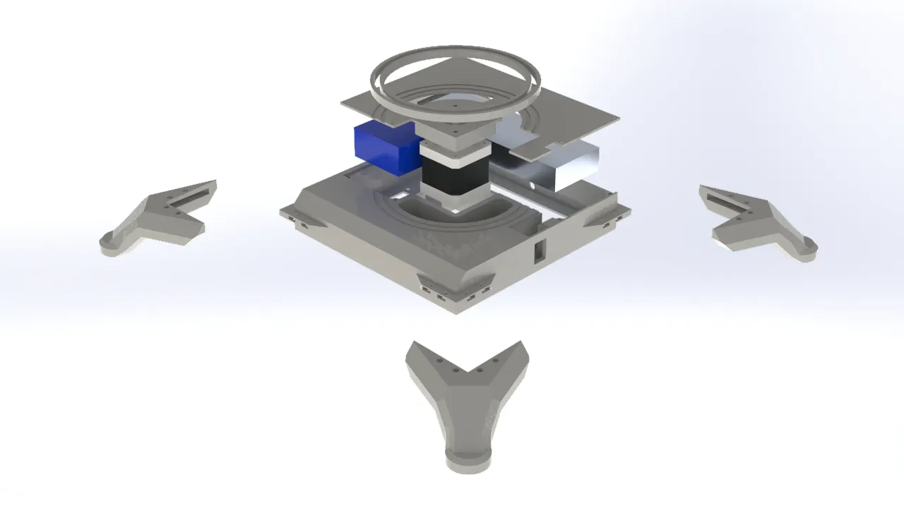
Base
When designing the robotic arm's base, I took into account all of the electronics that would be integrated into the system. I designed a square enclosure with dedicated space for a 12V power supply, which was necessary to power the entire system. I also incorporated an XL4016 voltage reducer to step the voltage down to 7V for the servomotors, along with space for an On/Off switch to safely cut power to the system. Finally, I allocated space for the Nema stepper motor responsible for the arm's rotation. To allow the components to connect with the rest of the structure, I added through-holes that communicated with the rest of the assembly.
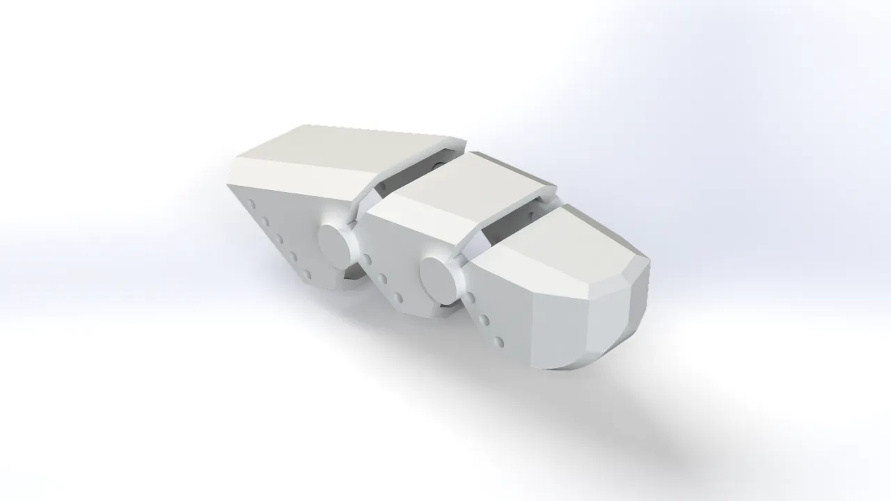
Articulations
For the robotic arm's joints, I considered the range of motion of the servomotors and carefully accounted for potential collisions between parts to ensure interference-free movement. I also identified and removed excess material from non-functional areas of each part to reduce the overall weight the servos would need to lift. For the mechanical connections, I used the brackets included with the servomotors, which were screwed directly onto the printed parts and secured with an additional bolt to keep each joint stable. Regarding the electronics, I placed them in the lower section of the rotating base. This decision was made with the arm's movement in mind, since cable routing could otherwise be affected by the rotation, having both the electronics and the structure rotate together was the most practical solution.
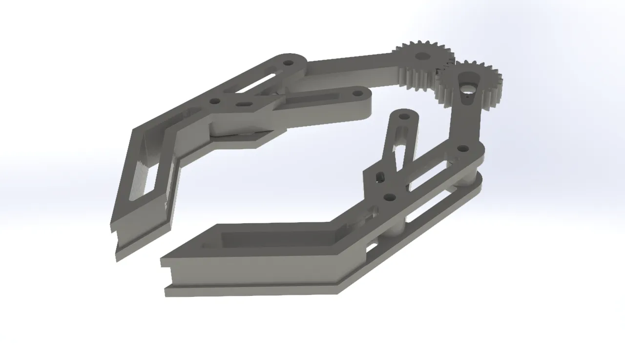
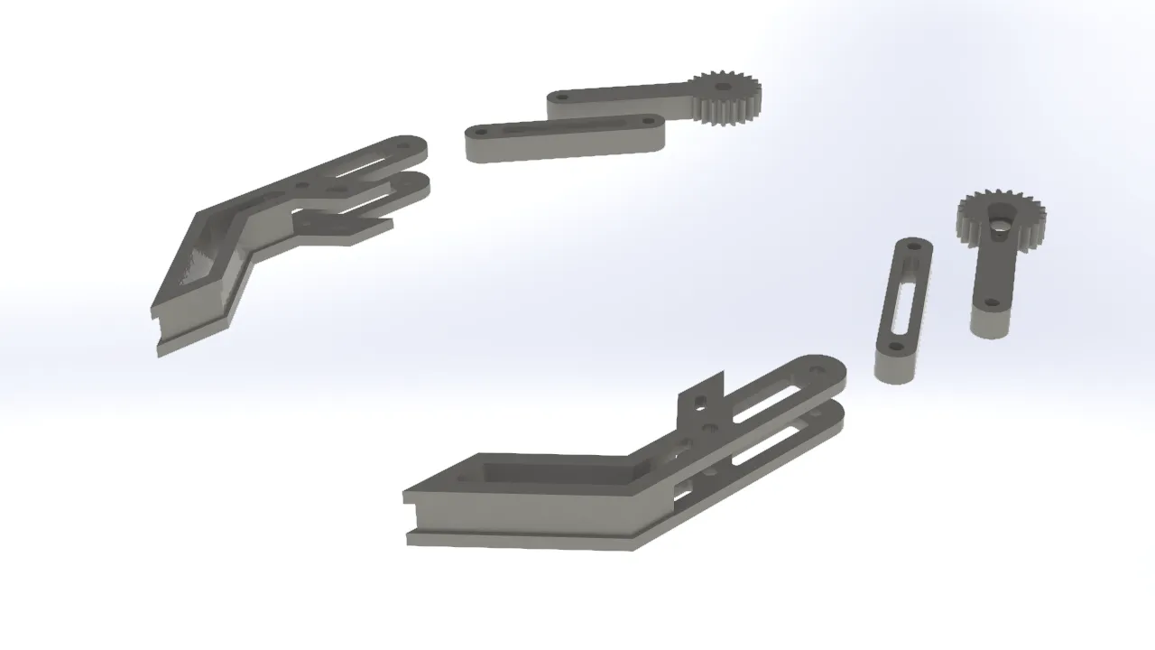
Gripper
For the gripper, I opted for a simple and traditional design commonly seen in other robotic arms. It consisted of a two-gear mechanism, with one gear connected to a servo. Each gear was linked to one side of the gripper jaw, so that when the servo-driven gear rotated, the gripper opened or closed depending on the direction of rotation. I added additional support beams to keep the gripper aligned and prevent it from tilting when opening or closing, which was important for achieving a more secure and consistent grip on objects.
Cable Organization
To clearly visualize the integration of the cables into the project, I created graphical representations of their distribution and connections.
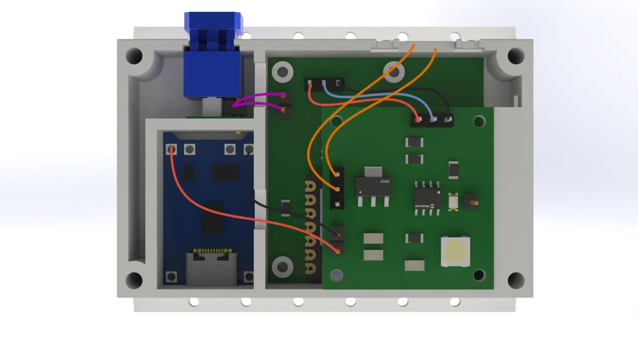
For the cable connections, I chose to use female pin connectors soldered to male pins to ensure a solid and reliable connection. Personally, I would have preferred to use a different type of terminal, but the limited space in the design did not allow for it. As a result, I opted for this solution which, while not ideal, was functional and well-suited to the project's requirements.
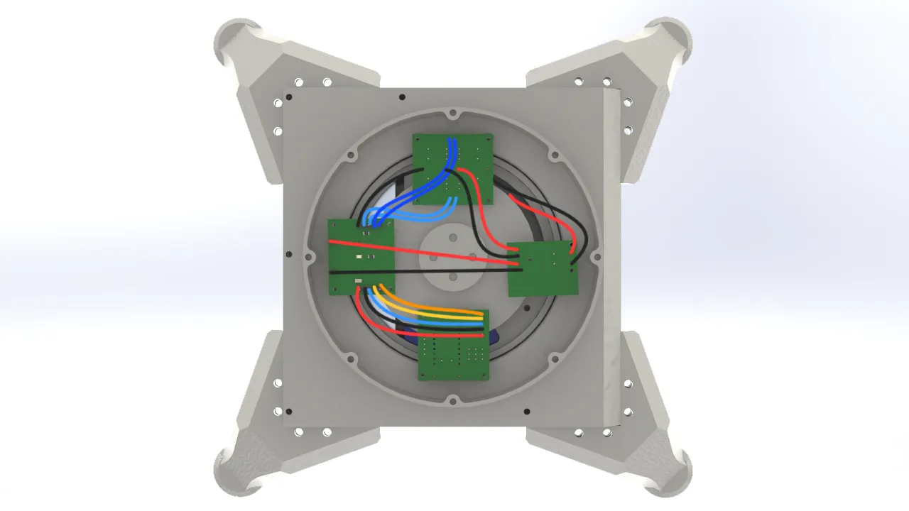
In this case, I chose to use Dupont-type connectors for the logic connections between the arm's electronics. This decision was made because the space inside the arm's base was more generous than in the glove, which meant there were no constraints preventing the use of this type of connector. While Dupont connectors are not as robust as pin connectors, they offered the practical advantage of being much easier to connect and disconnect.