3D Scanning and Printing
Experimenting with 3D printers during the group project taught me some universal rules of FDM manufacturing. Most importantly, I learned that gravity is the biggest enemy of 3D printing; any steep overhang or long bridge requires proper consideration or support structures, otherwise the molten plastic will simply collapse. Furthermore, I discovered that precise tolerances are extremely important for manufacturing moving parts. Without leaving the exact clearance between parts, hinged joints will either completely fuse together during printing or be too loose to function.
Group Assignment Week 5
This week, I focused on applying 3D design principles to create an object that could only be manufactured using additive manufacturing technologies. I also digitized a physical object in detail using 3D scanning.
3D Design in CAD Software
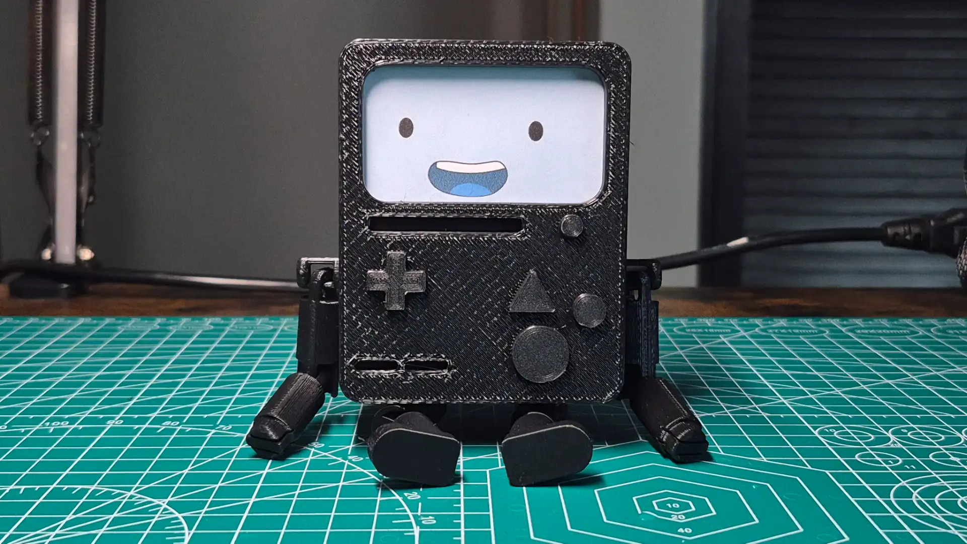
As an Adventure Time fan, I decided to design an articulated BMO figure using SolidWorks. The joints presented a significant challenge. I needed to limit their range of motion for example, preventing the elbow from bending backward, and calculate the correct clearance to prevent the parts from fusing together during printing. Furthermore, their joints are a good practice in additive manufacturing, since using other technologies it is very difficult, I would say almost impossible, to generate these chain shapes due to the complex tool entry angles.

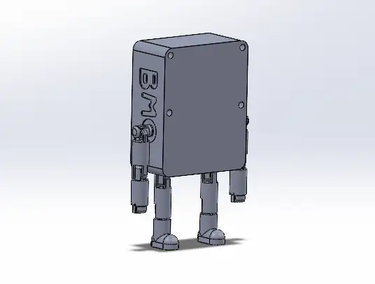
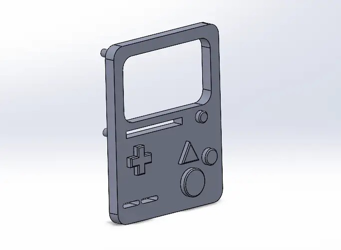
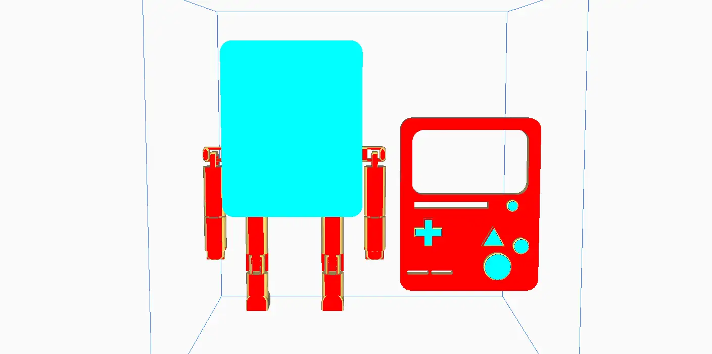
I designed the figure as a two-part assembly: the main body, which houses the articulated limbs, and a separate faceplate for the screen and buttons. This modular design allows me to 3D print different expressions and swap them out easily.
 BMO Body
 BMO Screen
BMO Body
The main body features chain-link joints with mechanical stops to prevent excessive bending. The iconic BMO lettering on the sides was created using extrusion cutting. To achieve a functional print model, I used reference drawings to separate the limbs from the body, maintaining the necessary tolerances for proper joint function.
BMO Screen
The removable front faceplate features the screen and molded buttons. It connects to the main body using mounting posts that fit into matching indents. To ensure these connecting features worked perfectly, I incorporated a 0.2 mm tolerance, allowing the parts to fit together securely without being too tight.
To get a realistic preview of the final result, I brought the individual components into a SolidWorks Assembly. I used the Mate tools to join the pieces digitally, ensuring that the modular design and the intended clearances worked perfectly together before sending anything to the 3D printer.
3D Scaning
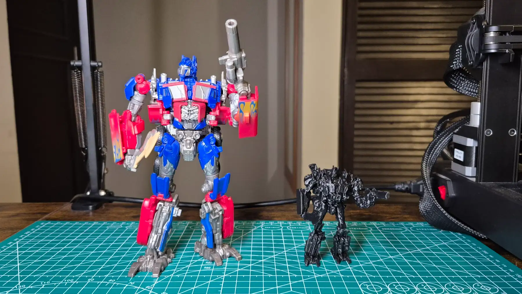
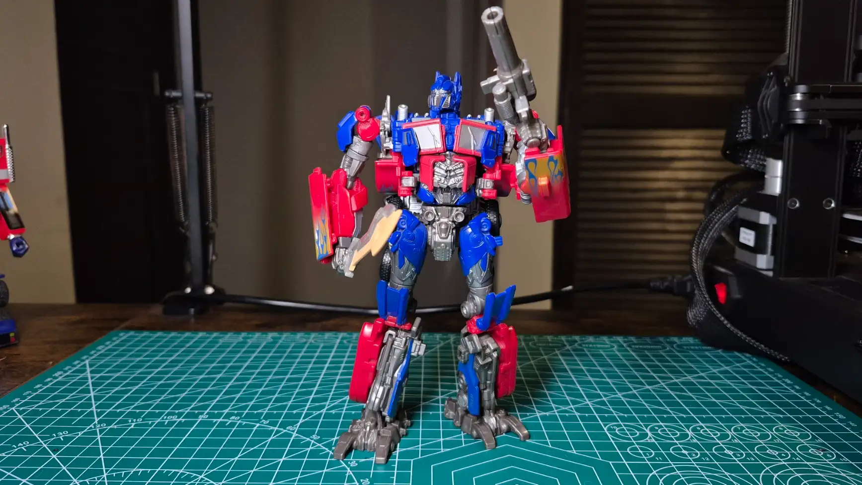
My chosen object for 3D scanning was the Studio Series 44 Optimus Prime. It was a challenging model because of its high level of detail and many moving parts. To get a complete 360-degree scan, I had to reposition the figure to capture hidden angles. The hardest part was keeping its pose completely locked, any shift in the articulated limbs would make it impossible for the software to stitch the scans together.
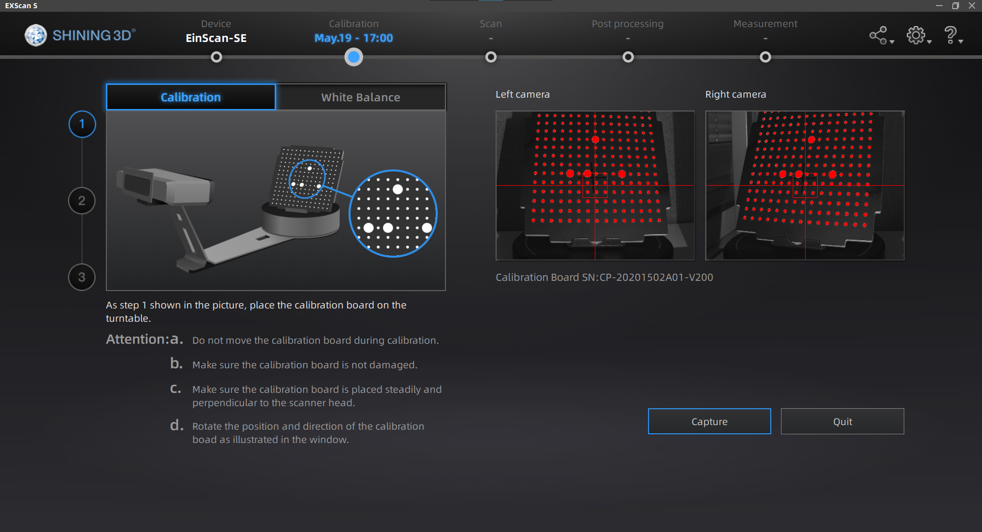
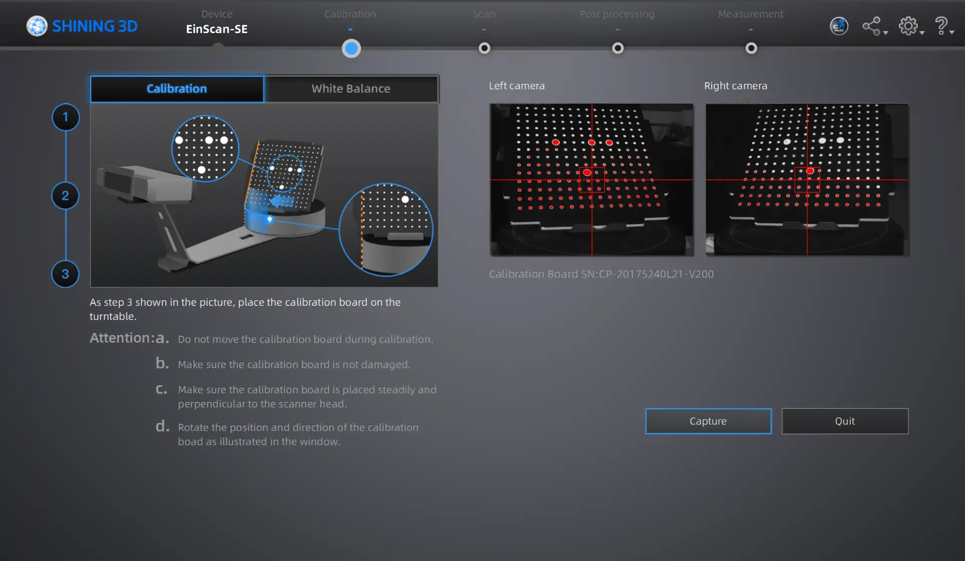
For the 3D scanning portion of the task, I used the Shining 3D scanner EinScan-SE along with its software, EXScan S. Before scanning my object, I performed the necessary hardware calibration.
How to Scan
- Setup: Place the object on the turntable and adjust the camera's brightness/exposure.
- First Scan: Run the automatic turntable scan to capture the initial geometry.
- Repositioning: Flip or rotate the object and run additional scans to capture hidden angles.
- Alignment: Ensure the software correctly merges the different scan passes.
- Cleaning: Manually delete noise, artifacts, and the turntable base from the point cloud.
- Meshing & Export: Generate the final watertight mesh and export the STL file.
After calibrating:
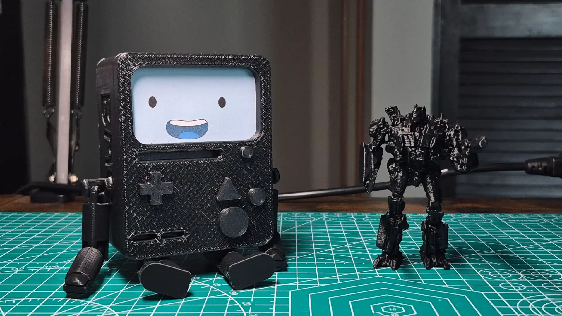
The scan successfully reproduced most of the figure's fine details. However, the black parts, such as the wheels, were not scanned at all. This happens because dark colors absorb the scanner's structured light, preventing the cameras from capturing data in those specific areas.
The digitization process of the Optimus Prime figure perfectly demonstrates the true power of 3D scanning technology. Replicating such complex, organic, and highly detailed surface geometries from scratch would require hours of work using traditional 3D modeling software. In contrast, 3D scanning allows us to capture these physical details and convert them into a high-precision digital mesh in a fraction of the time, making it an incredibly efficient tool for reverse engineering and rapid replication.
Printing Process
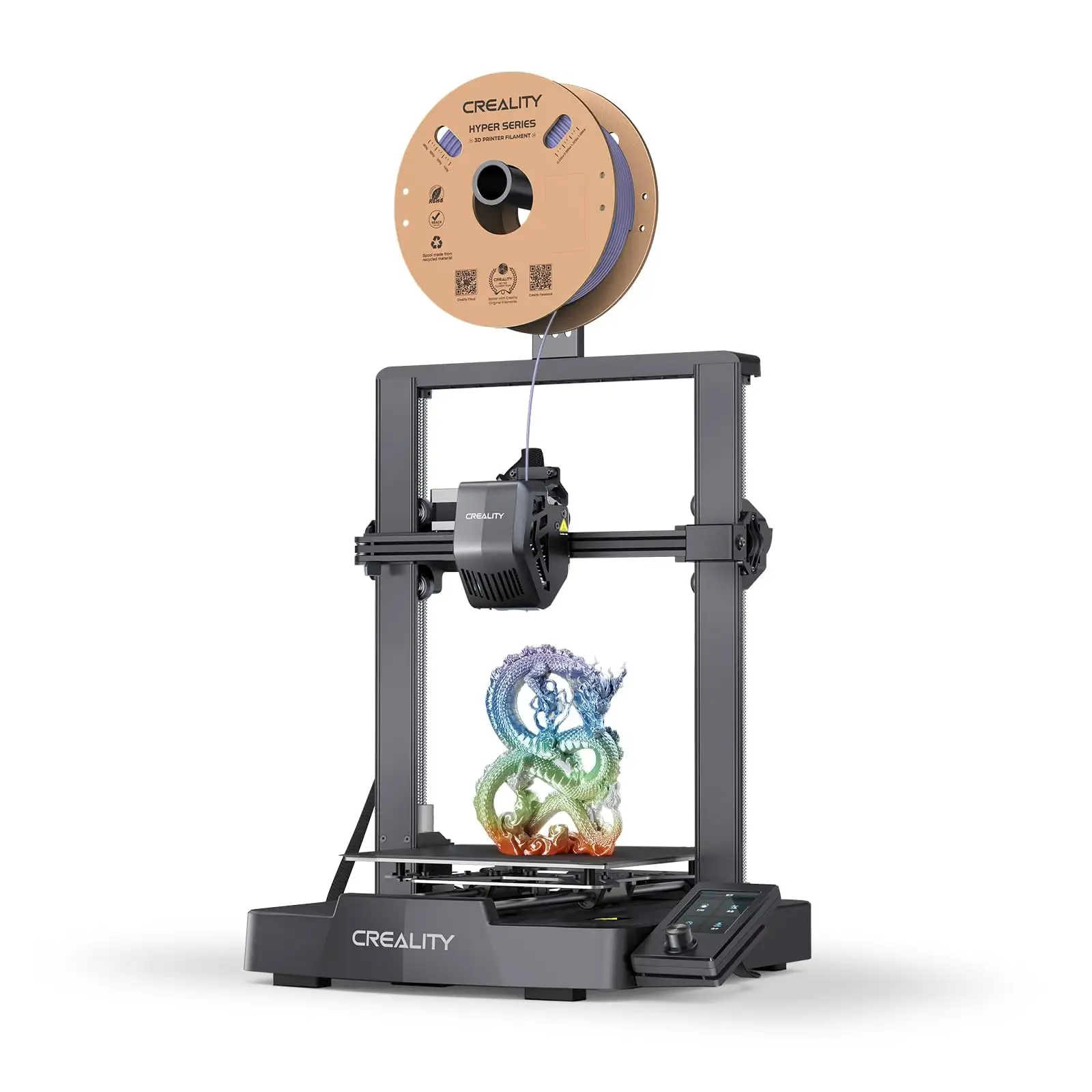
Creality Ender-3 V3 SE
- Extruder: "Sprite" Direct Drive capable of handling PLA, PETG, and flexible filaments
- Build Volume: 220 x 220 x 250 mm
- Bed Leveling: Automatic (CR Touch sensor)
- The printer handles angles up to 60 degrees successfully without needing support structures.
To understand the design rules and manufacturing limits of my available equipment, I characterized my personal 3D printer.
UltiMaker Cura
To prepare the model for manufacturing, I utilized UltiMaker Cura as my slicing software, translating the CAD geometry into the necessary G-code instructions.
Download UltiMaker Cura
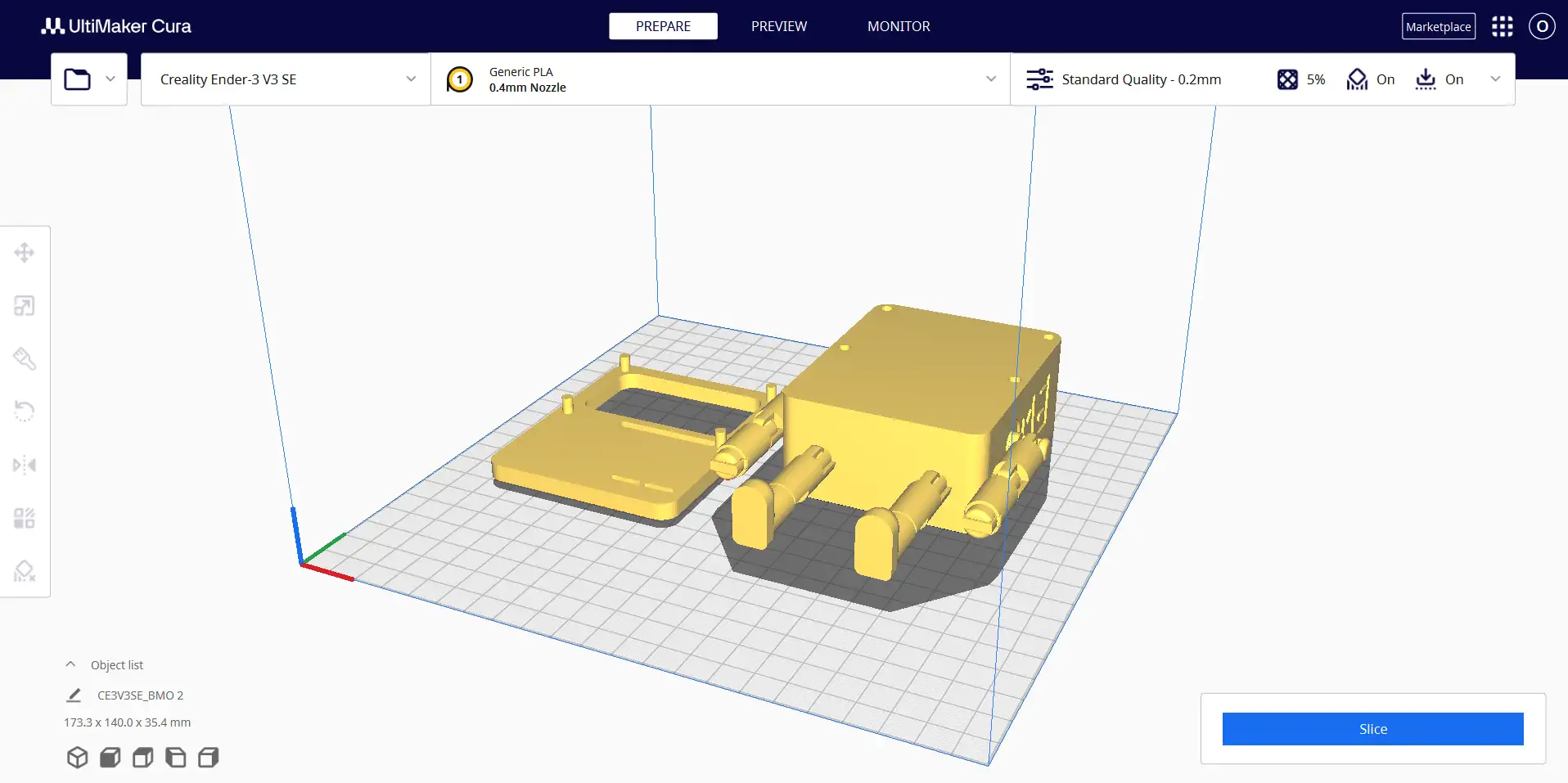
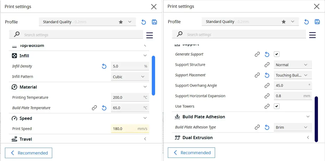
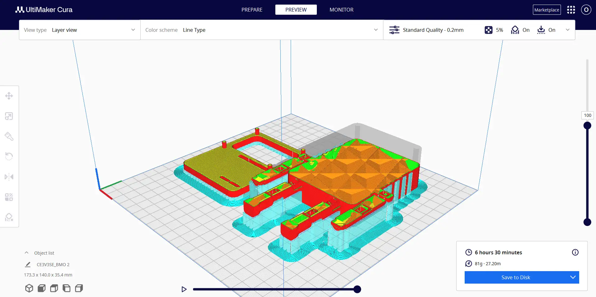
The initial 1 mm clearance gap was not enough to prevent friction between the moving parts. To fix this, I went back to CAD and slightly shrank BMO's main body while keeping the arms at their original size, which effectively increased the socket tolerance. Finally, to ensure the FDM printer could perfectly resolve these gaps without the walls fusing together, I imported the model into Cura and scaled everything uniformly to 170%.
Final results