Embedded Programming
For this week’s group assignment, we conducted a comparative study of various microcontroller architectures at FabLab Puebla. By analyzing datasheets and development workflows, we evaluated the hardware limitations and capabilities of chips ranging from AVRs to the ESP32.
Group Assignment Week 4
This week, we're exploring Embedded Programming. The goal is to interact with a microcontroller by processing input signals and generating output responses.
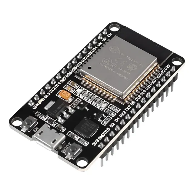
Microcontroller Characterization: ESP32-WROOM-32
I chose the ESP32 for this week because my Final Project requires wireless connectivity. To prepare for that, I started by reviewing the datasheet to understand its pinout and limitations. My goal for this task is not just to program a board, but to get closer to the ESP32 workflow so I can implement Wi-Fi communication in the future.
ESP32 Datasheet
-
Architecture: Xtensa® Dual-Core 32-bit LX6.
The dual-core architecture allows me to handle Wi-Fi and Bluetooth communication on one core while processing sensor data on the other. -
CPU Frequency: Adjustable between 80 MHz and 240 MHz.
High processing speed is critical for real-time calculations needed for the MPU6050 and servo control. -
Flash Memory: 4 MB External SPI.
Ample storage for the program code, libraries, and potential Over-The-Air (OTA) updates. -
Operating Voltage: 2.2 V to 3.6 V 3.3 V Logic.
Do not connect 5V logic directly to the GPIO pins to avoid damaging the board. -
ADC Resolution: 12-bit SAR ADC.
Allows for precise analog readings values ranging from 0 to 4095. -
Wireless Connectivity: 802.11 b/g/n Wi-Fi + Bluetooth/BLE.
Essential for the wireless communication aspect of my Smart Glove project.
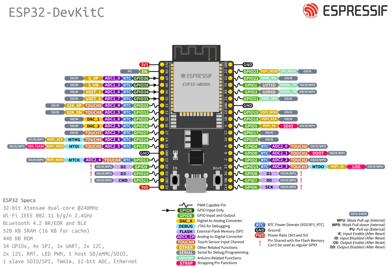
ESP32 Pinout
Programming and Simulation
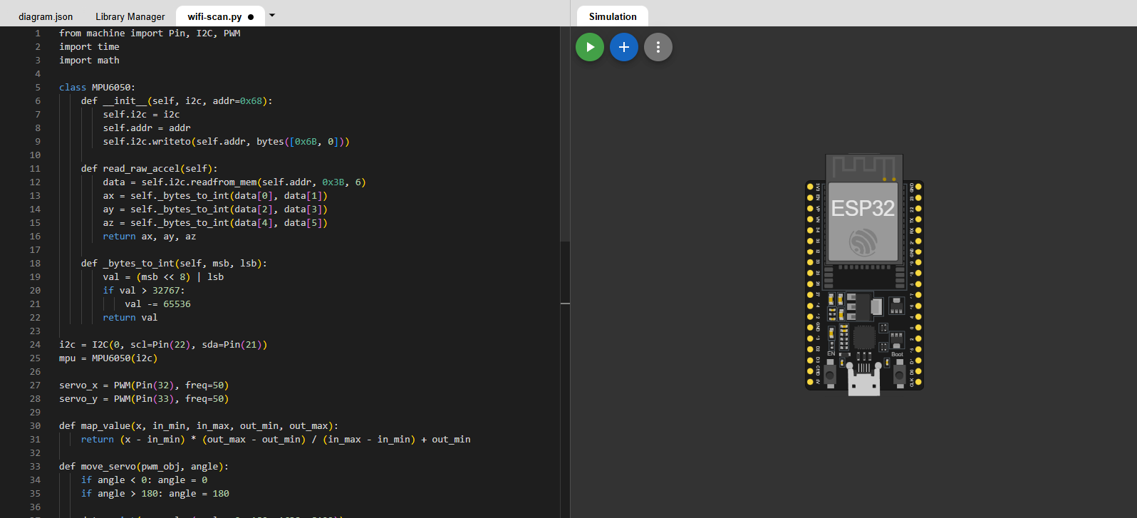
To program and test my code, I used the Wokwi simulator. It offers a wide range of microcontroller options and supports programming in C/C++ and MicroPython. It also allows you to place different electronic components to form circuits, including LEDs, buttons, sensors, servomotors, and more.
Wokwi
- Code Editor Left Panel: Where the logic is written (C++, MicroPython). It behaves like a standard IDE.
- Diagram View Right Panel: The visual workspace. You can add parts by clicking the "+" button and connect wires by clicking on the component pins.
- diagram.json: A tab that describes the hardware connections in text format. It updates automatically when you move wires in the visual view.
- Simulation Controls: The Green Play Button compiles the code and starts the simulation in real-time.
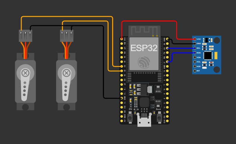
To connect inputs and outputs, I created a test circuit with an MPU6050 accelerometer and two servo motors. The goal was to convert physical movement into mechanical movement.
The ESP32 reads raw acceleration data from the MPU6050 via I2C. I mapped the acceleration values of the X and Y axis to the servos, scaling the data to control each motor from 0° to 180°.
Sensor
The MPU6050 is a 6-axis MotionTracking device based on MEMS (Micro-Electro-Mechanical Systems) technology, combining a 3-axis gyroscope and a 3-axis accelerometer on a single silicon die. It operates by measuring the microscopic displacement of internal suspended masses caused by linear acceleration or rotational forces, which alters the capacitance between fixed plates.
This analog signal is then processed by an internal 16-bit ADC converter and transmitted to the ESP32 via the I2C protocol, enabling accurate tilt and motion detection.
Important note:
The vcc of the servo motors is essential to connect to a voltage source independent of the controller, as the servos can generate current spikes and damage the controller.
I didn't do it in the schematic because I couldn't find a working source in the simulator.
 C++
C++
 MicroPython
#include <Arduino.h>
#include <Wire.h>

#define MPU_ADDR 0x68
#define REG_PWR_MGMT_1 0x6B
#define REG_ACCEL_XOUT_H 0x3B

#define SERVO_X_PIN 32
#define SERVO_Y_PIN 33

const int frequency = 50;
const int resolution = 16;

void setup() {
  Serial.begin(115200);
  Wire.begin();

  Wire.beginTransmission(MPU_ADDR);
  Wire.write(REG_PWR_MGMT_1);
  Wire.write(0x00);
  Wire.endTransmission(true);

  ledcAttach(SERVO_X_PIN, frequency, resolution);
  ledcAttach(SERVO_Y_PIN, frequency, resolution);
}

int angleADuty(int angle) {
  return map(angle, 0, 180, 1638, 8192);
}

void loop() {
  Wire.beginTransmission(MPU_ADDR);
  Wire.write(REG_ACCEL_XOUT_H);
  Wire.endTransmission(false);

  Wire.requestFrom(MPU_ADDR, 4, true);

  if (Wire.available() >= 4) {
    int16_t ax = (Wire.read() << 8) | Wire.read();
    int16_t ay = (Wire.read() << 8) | Wire.read();

    float gX = ax / 16384.0;
    float gY = ay / 16384.0;

    long angleX = map(ax, -16384, 16384, 0, 180);
    long angleY = map(ay, -16384, 16384, 0, 180);

    angleX = constrain(angleX, 0, 180);
    angleY = constrain(angleY, 0, 180);

    ledcWrite(SERVO_X_PIN, angleADuty(angleX));
    ledcWrite(SERVO_Y_PIN, angleADuty(angleY));

    Serial.print("Axis X: ");
    Serial.print(gX, 2);
    Serial.print(" g (");
    Serial.print(angleX);
    Serial.print("°) | Axis Y: ");
    Serial.print(gY, 2);
    Serial.print(" g (");
    Serial.print(angleY);
    Serial.println("°)");
  }

  delay(50);
}
I decided to use the Arduino framework as it is user-friendly and reduces the coding time required for basic functions.
Libraries and Definitions
#include <Wire.h>: Includes the library to handle I2C communication.MPU_ADDR 0x68: The hexadecimal I2C address of the MPU6050 sensor.REG_PWR_MGMT_1: The internal register responsible for the sensor's power mode.REG_ACCEL_XOUT_H: The starting register address where the X-axis acceleration data is stored.
Pin & PWM Configuration
const int frequency = 50;: Servomotors require a 50Hz signal (20ms period).const int resolution = 16;: We use 16-bit resolution for the PWM, giving us values from 0 to 65535 for very smooth movement precision.
Setup Function
Wire.begin(): Initializes the I2C bus on the default ESP32 pins (GPIO 21 SDA, GPIO 22 SCL).- >Waking up the sensor: The code sends a
0x00byte to the power management register to wake the MPU6050 from sleep mode. ledcAttach(...): A specific ESP32 command. It connects the GPIO pin to the internal hardware timer to generate the PWM signal.
The Helper Function: Angle to Duty Cycle
This function translates a requested angle (0°-180°) into the exact 16-bit PWM Duty Cycle the microcontroller needs to send. Standard hobby servos use a 50Hz control signal, which equals a 20ms period. Within that 20ms window, the duration of the HIGH pulse tells the servo where to move. The values 0.5ms and 2.5ms do not come from a physics equation, but rather from a industry hardware standard to define the physical limits of the servo's sweep 0° and 180°, respectively.
Because the ESP32's PWM resolution is set to 16 bits, the entire 20ms period is divided into 65,536 steps, from 0 to 65535. Using simple proportions, we calculate the duty cycle:
- 0.5ms is 2.5% of the 20ms cycle. (0.025 * 65536 = 1638)
- 2.5ms is 12.5% of the 20ms cycle. (0.125 * 65536 = 8192)
Main Loop
- Bitwise Operation (
<< 8 |): The MPU6050 sends data in two separate 8-bit bytes (High and Low). This line combines them back into a single 16-bit signed integer. map(...): Converts the raw acceleration data into servo angles. The sensor's 16-bit ADC is set to a ±2g range, meaning Earth's 1g gravity outputs exactly half the scale (ranging from -16,384 to 16,384). This ±1g raw data is then mapped directly to the 0°-180° servo rotation.constrain(...): A safety function. It ensures the angle never goes below 0 or above 180, protecting the servo mechanism.ledcWrite(...): Updates the PWM duty cycle, physically moving the motor.
C++ Simulation
from machine import Pin, I2C, PWM
import time
import math

class MPU6050:
    def __init__(self, i2c, addr=0x68):
        self.i2c = i2c
        self.addr = addr
        self.i2c.writeto(self.addr, bytes([0x6B, 0]))

    def read_raw_accel(self):
        data = self.i2c.readfrom_mem(self.addr, 0x3B, 6)
        ax = self._bytes_to_int(data[0], data[1])
        ay = self._bytes_to_int(data[2], data[3])
        az = self._bytes_to_int(data[4], data[5])
        return ax, ay, az

    def _bytes_to_int(self, msb, lsb):
        val = (msb << 8) | lsb
        if val > 32767:
            val -= 65536
        return val

i2c = I2C(0, scl=Pin(22), sda=Pin(21))
mpu = MPU6050(i2c)

servo_x = PWM(Pin(32), freq=50)
servo_y = PWM(Pin(33), freq=50)

def map_value(x, in_min, in_max, out_min, out_max):
    return (x - in_min) * (out_max - out_min) / (in_max - in_min) + out_min

def move_servo(pwm_obj, angle):
    if angle < 0: angle = 0
    if angle > 180: angle = 180

    duty = int(map_value(angle, 0, 180, 1638, 8192))
    pwm_obj.duty_u16(duty)

while True:
    ax, ay, az = mpu.read_raw_accel()

    angle_x = map_value(ax, -16384, 16384, 180, 0)
    angle_y = map_value(ay, -16384, 16384, 180, 0)

    g_x = ax / 16384.0
    g_y = ay / 16384.0

    move_servo(servo_x, angle_x)
    move_servo(servo_y, angle_y)

    print("Axis X: {:.2f} g ({}°) | Axis Y: {:.2f} g ({}°)"
          .format(g_x, int(angle_x), g_y, int(angle_y)))

    time.sleep(0.1)
Libraries and The MPU6050 Class
from machine import ...: Imports the hardware-specific modules to control Pins, I2C protocol, and PWM.- Class Structure: I encapsulated the sensor logic inside a class. This is Object-Oriented Programming (OOP).
__init__: The constructor method. It receives the I2C object and wakes up the sensor by writing 0 to the power management register 0x6B.
Reading and Bit Manipulation
readfrom_mem: Reads 6 bytes at once starting from register 0x3B, the acceleration X, Y, and Z.- Bitwise Operation (
<< 8): Python needs manual help here. We shift the High Byte 8 positions to the left and combine it with the Low Byte using OR (|). - Signed Integer Handling: Since the sensor outputs 16-bit signed integers (-32768 to 32767), but Python integers are infinite, we manually convert values greater than 32767 into negative numbers.
Hardware Initialization
I2C(0, ...): Initializes the I2C bus on the physical pins 22 (SCL) and 21 (SDA) of the ESP32.PWM(..., freq=50): Configures the pins to output a PWM signal at 50Hz, which is the standard frequency required for analog servomotors (20ms pulses).
Mapping and Moving Servos
This part is crucial. In MicroPython, PWM duty cycle is defined as a 16-bit integer (0 to 65535).
- Why 1638? This represents ~2.5% duty cycle (0.5ms pulse), which is 0 degrees.
- Why 8192? This represents ~12.5% duty cycle (2.5ms pulse), which is 180 degrees.
duty_u16(duty): Applies the calculated duty cycle to the pin.
Main Loop
- The loop continuously reads raw acceleration.
- It maps the raw gravity values (~ +/- 16384) to servo angles.
time.sleep(0.05): A small 50ms delay to stabilize the servo movement and prevent jitter.
MicroPython Simulation
After verifying the logic in the simulator, I proceeded to test the code on the physical hardware to ensure it behaves as expected.
Moving forward, I plan to use MicroPython. Since I am already comfortable with C++ and Arduino, I want to challenge myself to learn Python's capabilities. The hardest part for me was getting used to the syntax: unlike C++, where blocks are defined by curly braces {}, Python uses indentation to structure the code.