I approached two 2D design software programs, Inkscape and Affiniti, from Camva. What I did was, as I already said,
a logo related to my final project. I took the image, vectorized it, and modified it with the software tools,
then exported it as a .jpg. I used Gemini as a reference image, since I'm not a very good artist.
I've attached the original image and the prompt I used.
Prompt Used:
"Create a circular, technical-style vector logo that represents the intersection of robotics and human anatomy.
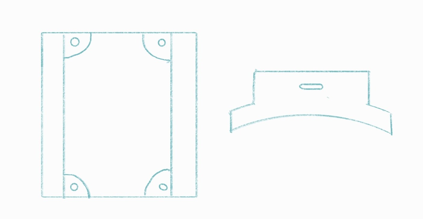
In the center, there should be a robotic arm based on my sketch of my final project,
positioned in front of a stylized black human hand with integrated circuit patterns and microchip lines on its surface."
Inkscape
Inkscape is a free and open-source vector graphics editor used to create and edit vector graphics.
This program is primarily used to create logos, illustrations, and artwork that require high quality and scalability.
Download Inkscape
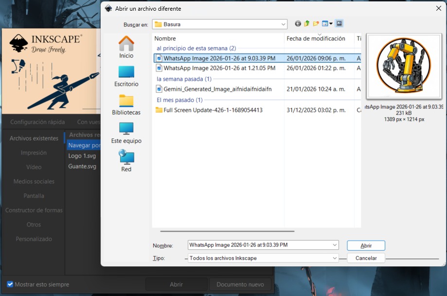
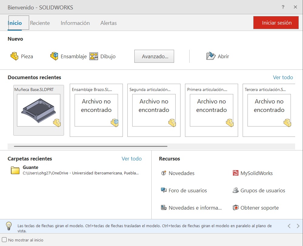
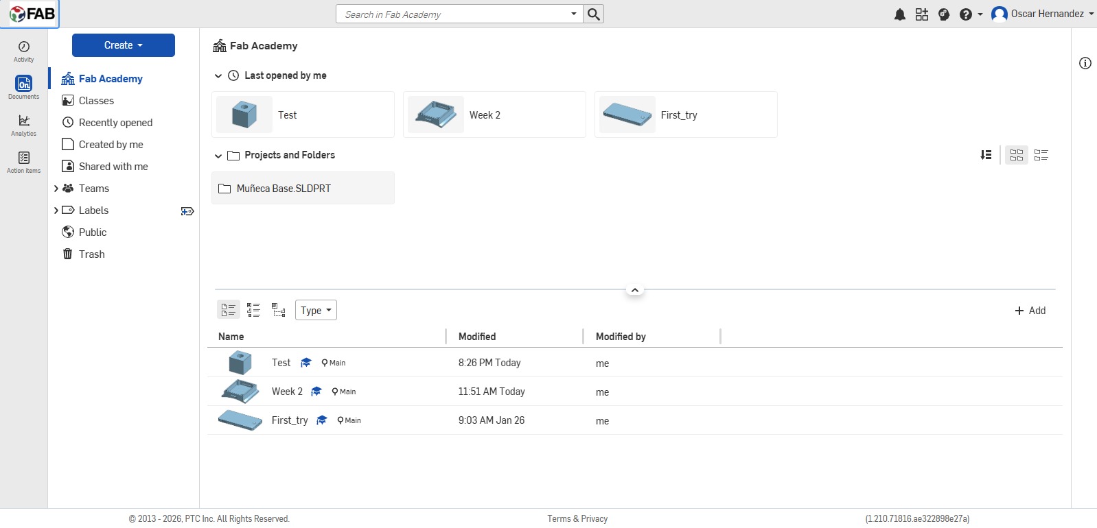
When you open Inkscape, a window will pop up where you can open previous projects, create new ones, or import files to modify them.
In my case, I imported the AI-generated image using the "open" option, selected the image, and clicked "open" again.
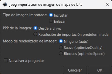
Another window will appear to configure the import; personally, I don't change anything and just click OK.
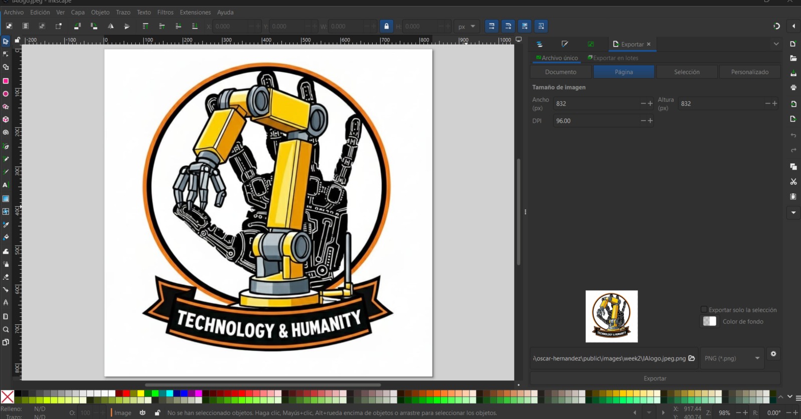
After that, the image will open, ready to be modified.
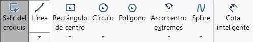
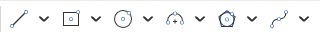
Essential Inkscape Tools
-
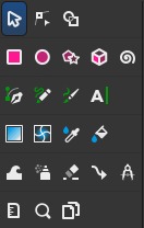
Select and transform objects, mouse cursor icon: This is the main tool for interacting with your design; it allows you to select objects, move them around the canvas, change their size or rotate them.
-
Edit path nodes, arrow icon over points: This is fundamental to technical drawing, as it allows you to modify the internal structure of a vector shape by moving its individual points or adjusting the curvature of its lines.
-
Shape Creation: The square and circle icons allow you to generate perfect geometry.
-
Drawing Bézier Curves, the pen tool: Represented by the fountain pen icon, this is the most powerful tool for vectorizing. It allows you to draw straight lines and smooth curves point by point.
-
Fill and Stroke: Using the Paint Bucket or Eyedropper icon, you can define the internal color of shapes and the thickness of their lines.
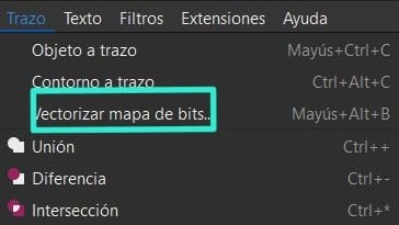
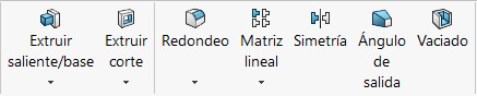
Vectorize Bitmap
In order to modify the image I had to vectorize it, using the vectorize bitmap option located in the Stroke drop-down menu at
the top of the screen.
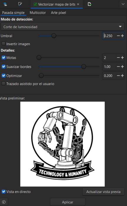
A window will open on the right side of the screen where you will see 3 options for vectorizing bitmaps: single pass, multicolor,
and pixel art. Single pass generates a single black and white vector path based on a brightness threshold, ideal for silhouettes
and line drawings. Multicolor allows you to break down the image into multiple layers of color or gray levels, recreating the visual
complexity of the original by overlapping shapes. Pixel art is a specialized function for low-resolution images that translates each
pixel into a precise geometric shape, maintaining the grid aesthetic without blurring the edges.
I used the parameters shown in the image. After applying vectorization, delete the original image to work with the result.
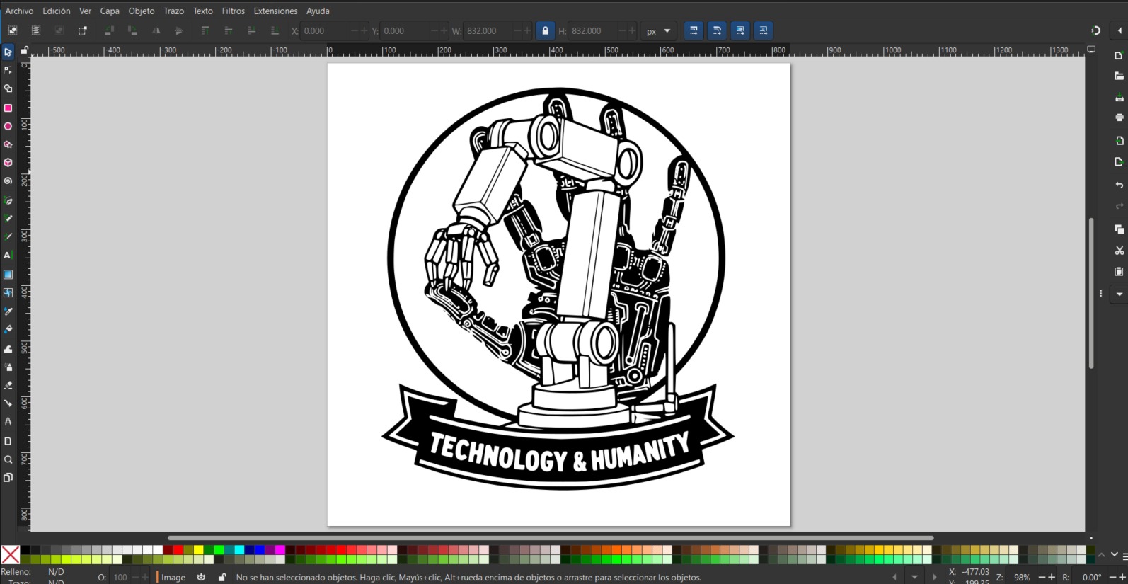
The first change was removing the "Technology & Humanity" text from the bottom of the logo using the eraser tool.
Then, with the node tool, I tweaked the details slightly to improve their appearance.
Using the paint bucket tool, I filled the arm with colors that matched my website. Finally, with the pen tool,
I added highlights and shadows to give the drawing more detail.
Affinity
Affinity Designer is a free, professional graphic design software that combines vector and pixel-based tools in a single,
fluid interface. It's ideal for creating logos, illustrations, and digital art that require maximum precision,
standing out for its high speed. A Canva account is required to use the software.
Download Affinity
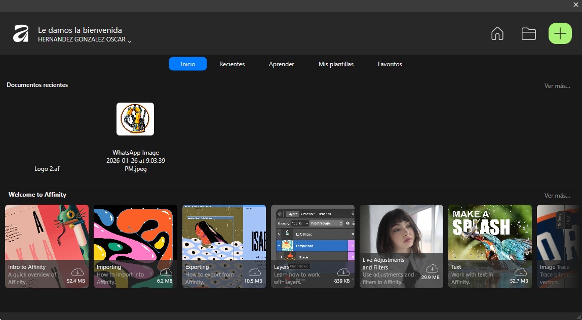
When you open Affinity, a window pops up where you can see recent projects, create new files, and also find tutorials as
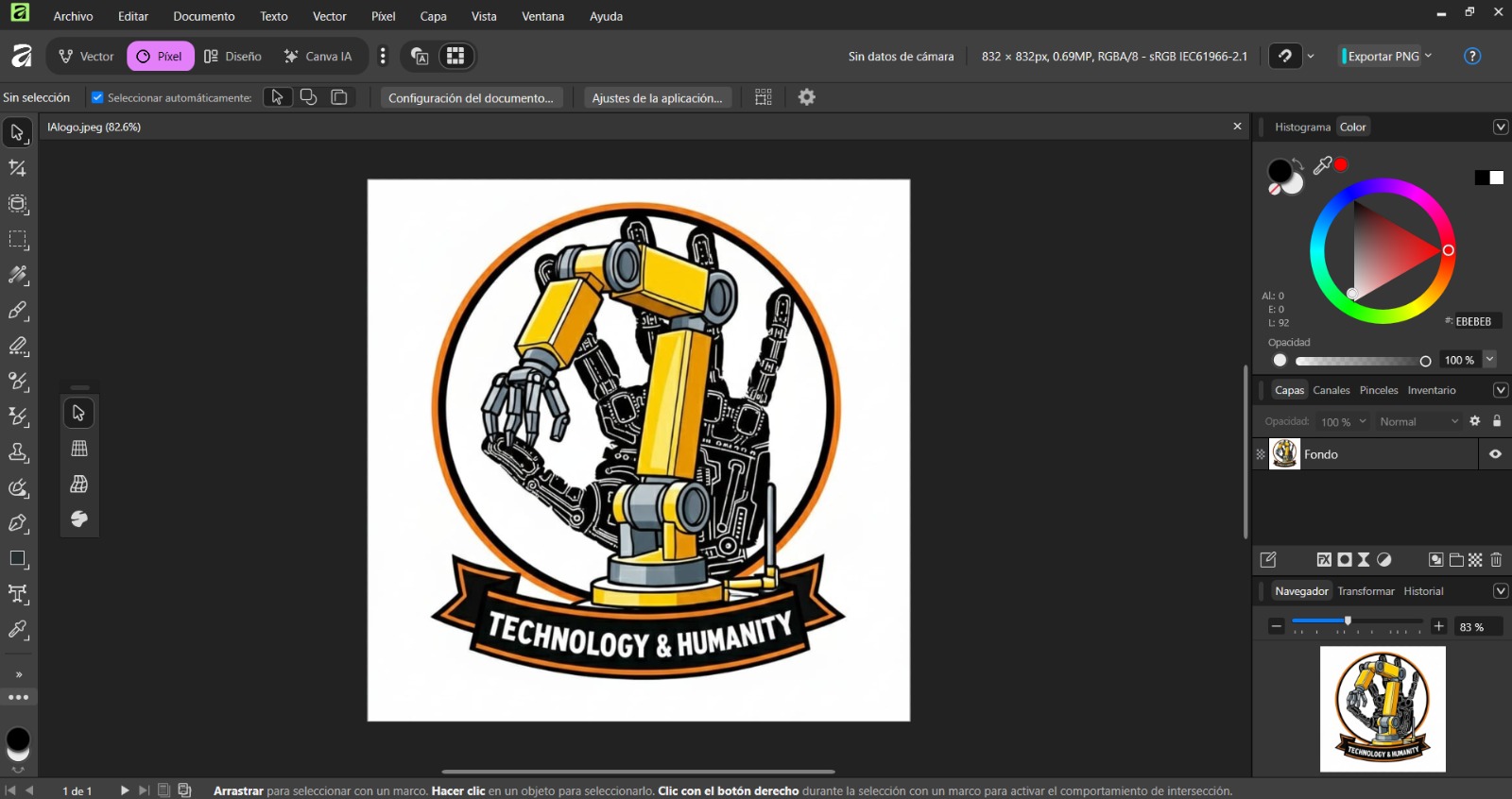
a welcome to Affinity. To modify the AI-generated image, simply click on the button with the folder symbol and select
the image you want to modify.
After that, the image will open, ready to be modified.
Affinity Studies
Affinity has four studies, of which we will look at two.
-
Vector Studio: This is the heart of precision design. Here you work with nodes and curves based on mathematical equations, allowing you to scale your designs to infinity without losing sharpness.
-
Pixel Studio: This is the space dedicated to image processing and digital painting. Here you work with a pixel grid, allowing you to apply textures, realistic brushstrokes, and photo retouching.
Vectorization with Affinity
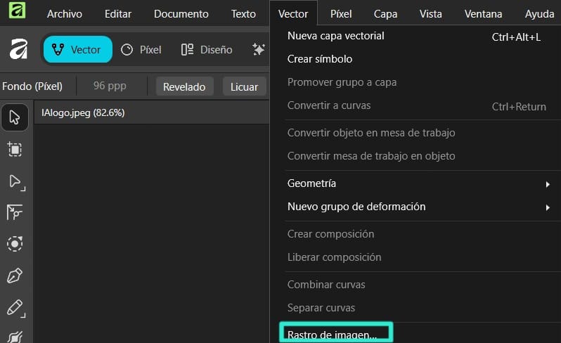
To vectorize the image, we must select the vector studio, select the image, open the drop-down menu called Vector located at the top, and then click on image trace.
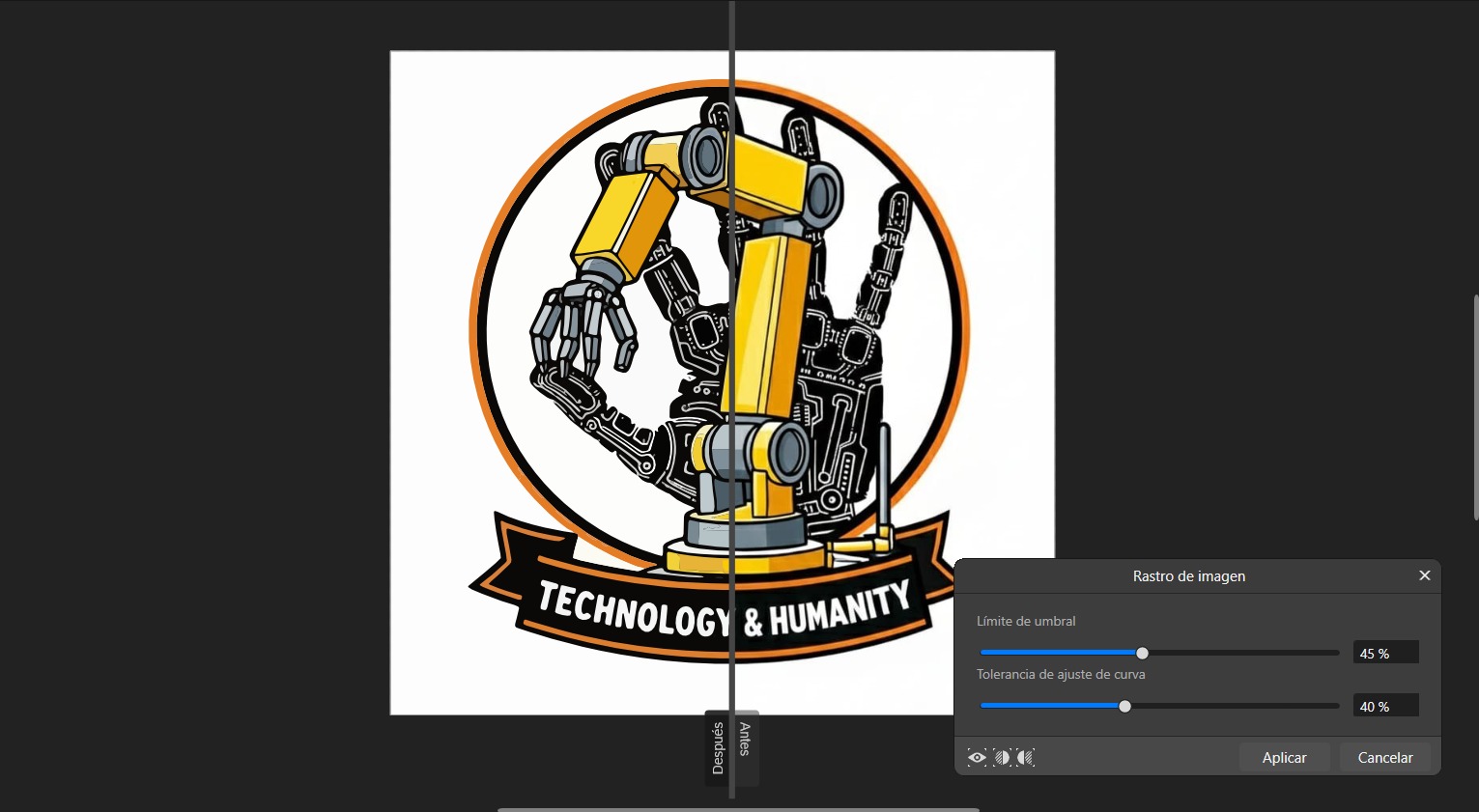
A small window will open with two parameters: threshold limit, which regulates the tool's sensitivity to pixel brightness,
and curve adjustment tolerance, which determines the vector's fidelity to the bitmap. A higher tolerance simplifies shapes by
creating smoother curves with fewer nodes. There will also be an option to split the project to view the before and after
in real time.
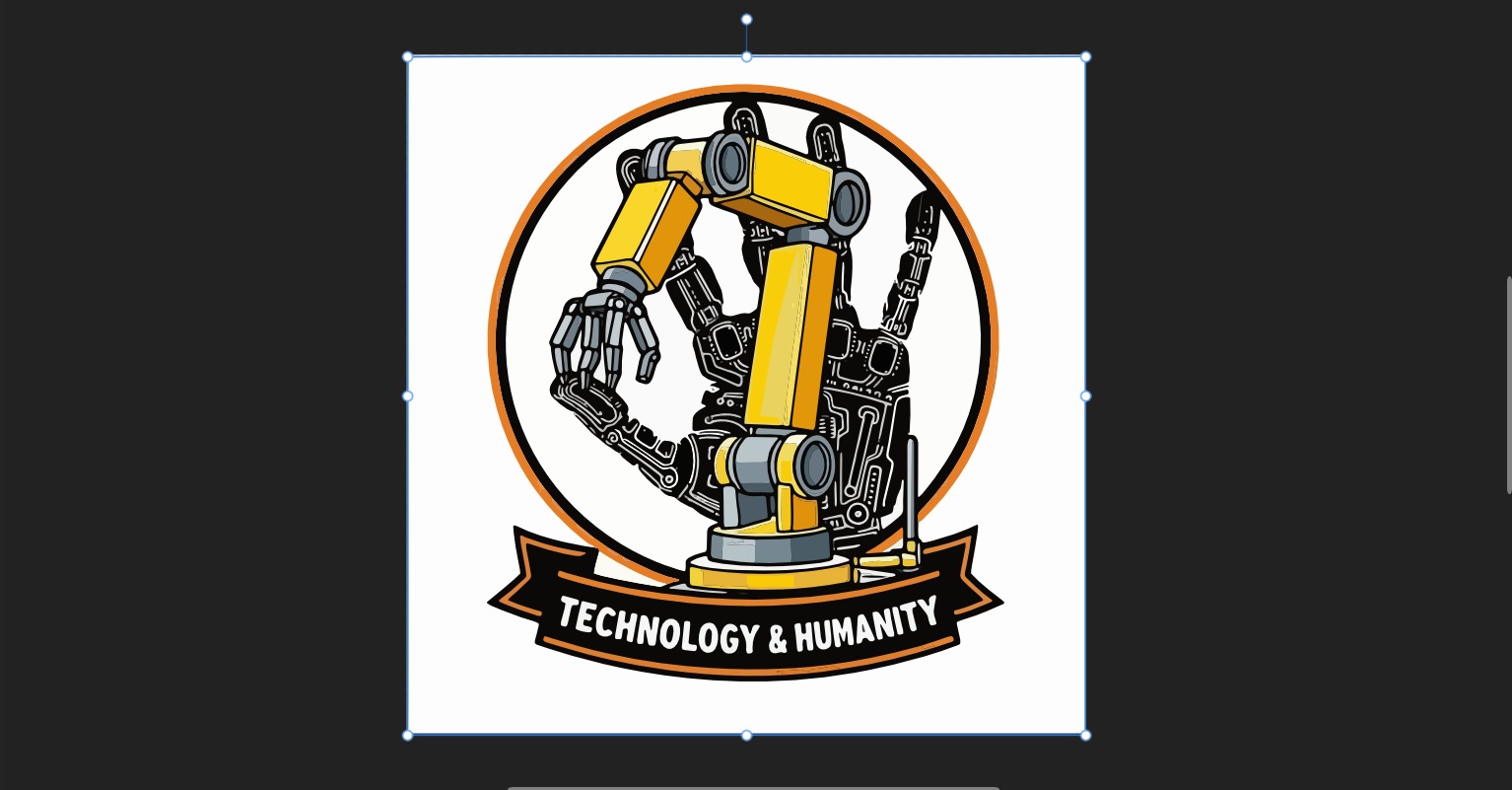
When you click apply, it transforms the pixel image into vector-based figures.
As in Inkscape, the first change was to remove the text "Technology and Humanity" from the bottom of the logo using the Eraser
brush tool. With the Vector Fluid Fill tool, I filled the arm with colors that matched my website. Since the lighting and shadows
were preserved in this software, I only had to change their colors.
Personal Opinion of 2D softwares
As an engineering student, my workflow has been closely tied to the technical precision of Inkscape, so the transition to
Affinity has represented a significant shift in my 2D design experience. While I'm aware that I've only just begun to explore
Affinity's capabilities and professional potential, the tools I've tried so far haven't managed to displace my familiarity with it.
When comparing the features and logic of both programs, I still prefer Inkscape for now, as it better suits my current needs
and the agility I seek in my projects.
2D Design Files