Group assignment
Objective
-
demonstrate and compare the toolchains and development workflows for available embedded architectures
Here I share the link to my group assignment.
The final reflection can be found at the end of the page.t
indivual assignment
Objectives
-
browse through the data sheet for a microcontroller
-
write and test a program for an embedded system using a microcontroller to interact (with input &/or output devices) and communicate (with wired or wireless connections)
Browsing through the datasheets
To begin with, I am interested in two microcontrollers: ESP32 and RP2040. I have not previously worked directly with either of them. However, during my research, I realized that the Raspberry Pi Pico board is based on the RP2040 microcontroller.
I had previously used the Raspberry Pi Pico in educational projects with children, such as a small soil moisture detection system. At that time, I did not review the datasheet or pay attention to the specific microcontroller used on the board, so I was not aware that I was actually working with an RP2040 or RP2350.
Here you can find additional information and official documentation about the Raspberry Pi Pico.Below, I present a short video as evidence of my prior use of the Raspberry Pi Pico.
evidence
Regarding the ESP32 microcontroller, I am certain that I have never used it before. I selected the ESP32 and RP2040 microcontrollers for this analysis because both provide a high number of input and output pins, which is a relevant characteristic when evaluating different options for a development project.
Although I am interested in exploring both microcontrollers, it is still necessary to determine which one better fits the specific requirements of my final project. For this reason, I conducted a technical comparison based on the information provided in the respective datasheets of each device.
To evaluate and select the microcontroller that I will use for my final project, I will analyze whether the chip includes wireless communication interfaces such as Wi-Fi or Bluetooth, since this type of communication will be required for the project, at least one of these two technologies.
lthough wireless connectivity can be added to many microcontrollers by using external Wi-Fi or Bluetooth modules through interfaces such as UART, I preferably want the selected microcontroller to have these interfaces integrated, in order to simplify the hardware design.
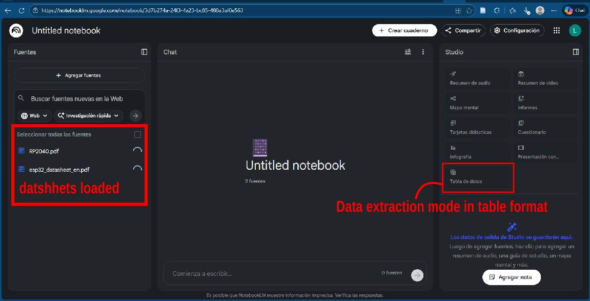
To summarize both datasheets, I relied on Artificial Intelligence tools, specifically NotebookLM , since both documents contain a large amount of technical information spread across many pages. When reviewing them manually, it was easy to get lost among the different sections, tables, and specifications. Using this tool allowed me to more efficiently identify and extract the most relevant information for comparing the microcontrollers.
The first step was to provide the Artificial Intelligence tool with the datasheet of each microcontroller, in this case the RP2040 and the ESP32. Afterwards, I submitted a prompt requesting the creation of a comparative table between both chips, focusing on the most relevant technical characteristics.
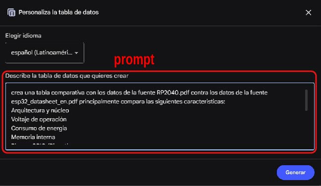
Prompt provided to the Artificial Intelligence tool to generate the comparison.
" crea una tabla comparativa con los datos de la fuente RP2040.pdf contra los datos de la fuente esp32_datasheet_en.pdf principalmente compara las siguientes caracteristicas: Arquitectura y núcleo, Voltaje de operación, Consumo de energía, Memoria interna, Pines y GPIO (Pinout), Periféricos integrados, Interfaces de comunicación, Sistema de reloj, Programación y depuración, Condiciones ambientales, Límites eléctricos, Encapsulado (Package), Diagramas y tablas clave"
In the following comparative table of both microcontrollers, the most relevant characteristics of each one can be observed, which are of greatest interest for this analysis.
Based on the comparative table, it can be observed that the RP2040 does not include Wi-Fi or Bluetooth communication interfaces, which leads to it being excluded from this project. In contrast, the ESP32 integrates both wireless communication interfaces, making it the most suitable option and therefore the selected microcontroller.
| Feature | RP2040 (Raspberry Pi) | ESP32 (Espressif Systems) |
|---|---|---|
| Architecture and Core | Dual ARM Cortex-M0+ @ 133 MHz, ARMv6-M architecture. | 32-bit Xtensa® LX6 (single or dual core) up to 240 MHz. |
| Operating Voltage | Digital I/O: 1.8 V – 3.3 V; Core: 1.1 V. | 2.3 V – 3.6 V (recommended 3.3 V). |
| Power Consumption | Dormant: 0.18 mA; Sleep: 0.39 mA. | From 5 µA (hibernation) up to 240 mA (Wi-Fi active). |
| Internal Memory | 264 kB SRAM + 16 kB ROM. | 448 kB ROM, 520 kB SRAM, 16 kB RTC SRAM. |
| Pins and GPIO | 30 multifunction GPIO + 6 QSPI pins. | 34 programmable GPIO. |
| Integrated Peripherals | PIO, DMA, ADC, PWM, timers, temperature sensor. | ADC, DAC, capacitive touch, Hall sensor, ULP coprocessor. |
| Communication Interfaces | UART, SPI, I2C, USB, PWM. | Wi-Fi, Bluetooth, UART, SPI, I2C, I2S, CAN. |
| Clock System | Internal PLL, external crystal, up to 133 MHz. | Internal oscillator, external crystal, RTC clock. |
| Programming and Debugging | 2-wire SWD interface. | JTAG, secure boot support. |
| Environmental Conditions | −40 °C to 85 °C. | −40 °C to 125 °C (depending on variant). |
| Electrical Limits | Max I/O voltage: IOVDD + 0.5 V. | Max voltage: 3.6 V. |
| Package | QFN-56 (7 × 7 mm). | QFN-48 (6 × 6 / 5 × 5 mm). |
| Key Diagrams and Tables | Address map, GPIO functions, boot sequence. | Functional block diagram, pinout, power schematic. |
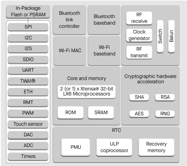
ESP32
The ESP32 features a 32-bit dual-core Xtensa® LX6 architecture, making it a powerful microcontroller with integrated Wi-Fi and Bluetooth. However, one of its main drawbacks is its high power consumption, especially in battery-powered applications.
Diagram ESP32
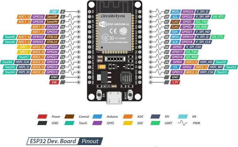
ESP32 GPIO Classification
| Category | GPIO Pins | Description |
|---|---|---|
| Safe Pins | 13, 14, 16, 17, 18, 19, 21, 22, 23, 25, 26, 27, 32, 33 | Recommended for general use. These pins do not affect the boot process and can be safely used as digital inputs or outputs. |
| Dangerous Pins | 0, 2, 4, 5, 12, 15 | Boot (strapping) pins. Incorrect wiring may prevent the ESP32 from booting properly. |
| Not Recommended | 1, 3 | Used for UART0 (programming and serial communication). Avoid using these pins for external components. |
| Input Only | 34, 35, 36, 39 | Input-only pins. They cannot be used as digital outputs (LEDs, relays, or actuators). |
| Conditional Use | 25, 26 | ADC2 pins. They may conflict with WiFi usage, although they can be used as DAC outputs. |
Programing using ESP32
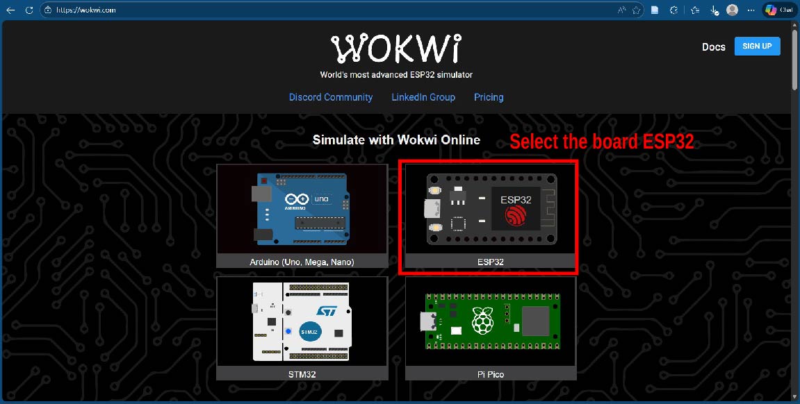
To simulate the use of the ESP32, I used the Wokwi tool, which allows testing the code and connections virtually without physical hardware.
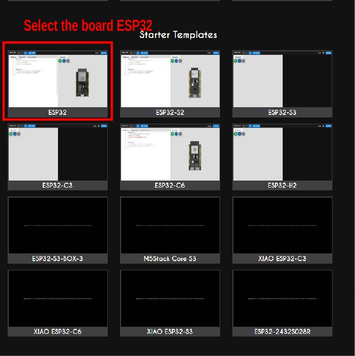
Once on the Wokwi platform, I selected the board I wanted to use, in this case the ESP32.
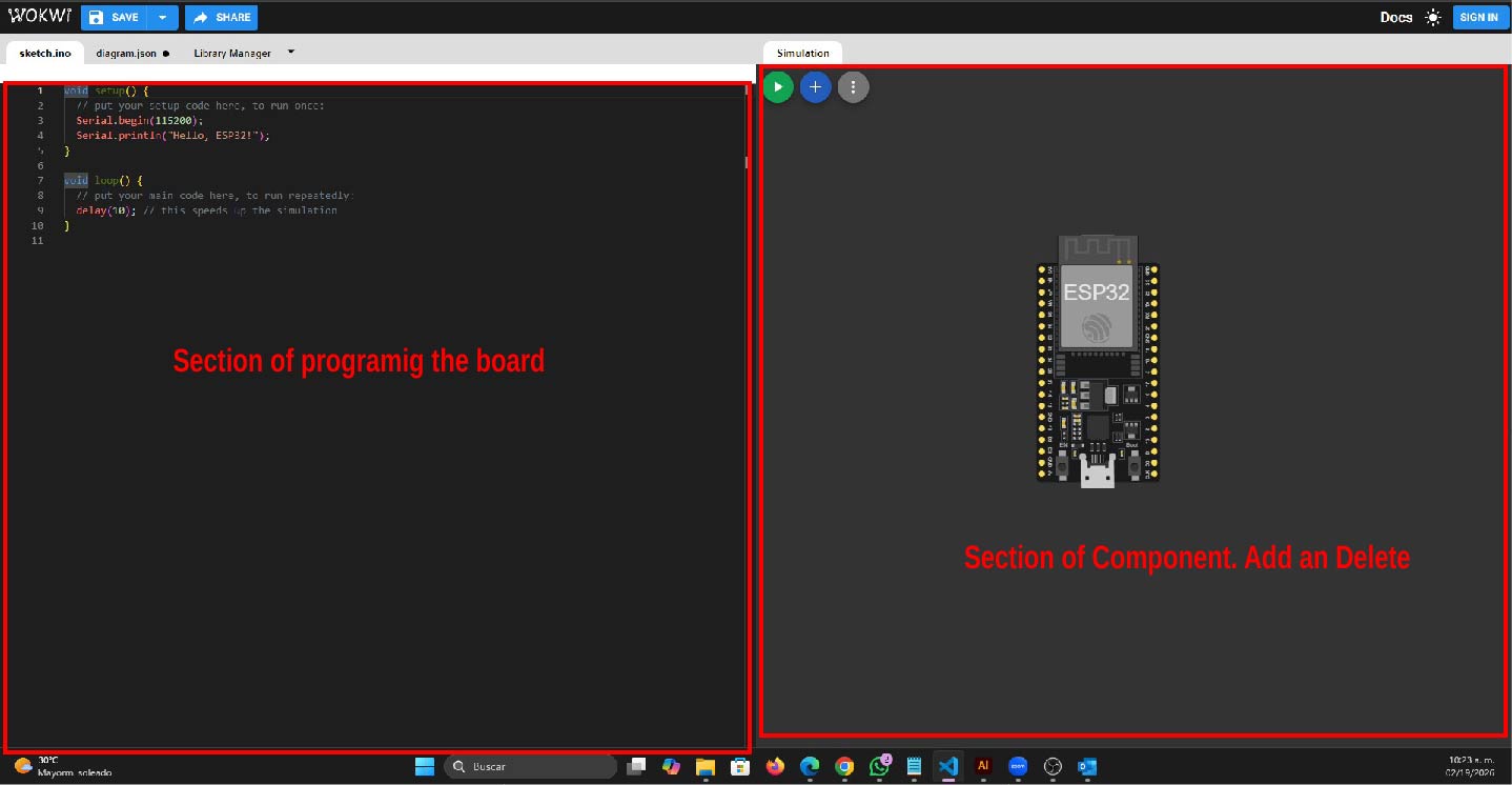
Once in the interface, as it was my first time using this tool, I started exploring it. The first thing I did was a light pattern using an ESP32 and a NeoPixel WS2812, as shown in the following video.
evidence
Next, I explain how I did it.
-
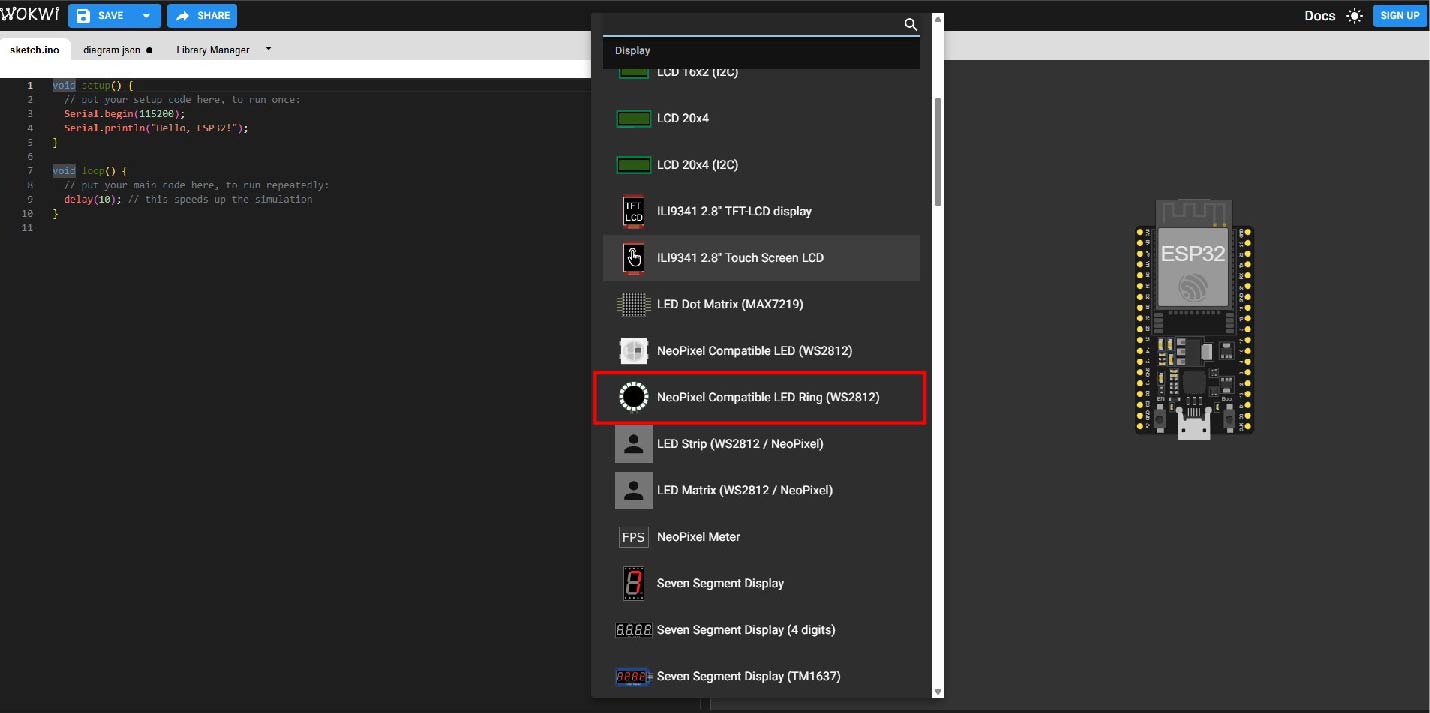
The first thing I did was add the NeoPixel WS2812, the ESP32, and a resistor to the component section, which are necessary for the circuit to operate.e
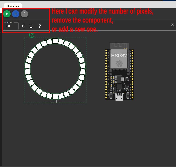
-
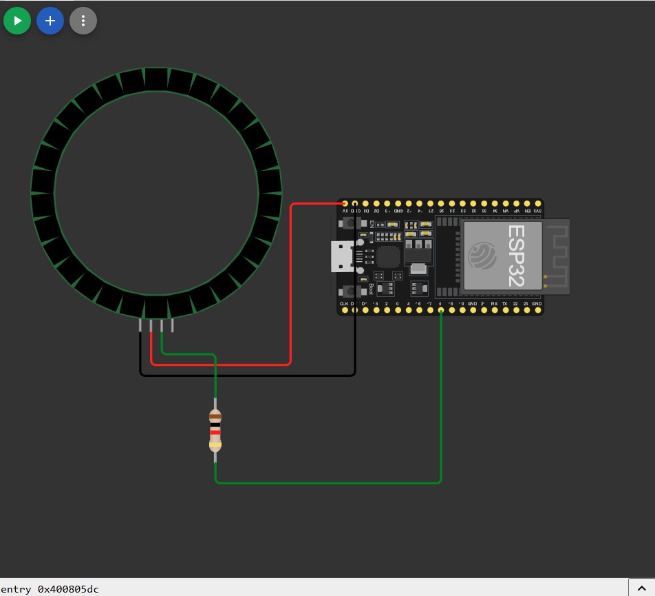
Subsequently, I defined the connection pins to link the NeoPixel WS2812 with the ESP32.
NeoPixel WS2812 – ESP32 Pin Connections
NeoPixel WS2812 ESP32 Description VCC 5V Power supply GND GND Common ground DIN GPIO 5 Data signal pin The final connection was as follows: the NeoPixel is powered using the 5V provided by the ESP32, by connecting the NeoPixel VCC pin to the 5V pin on the ESP32. In addition, the NeoPixel DIN pin is connected to GPIO 5, which acts as the data pin and allows control information to be sent to the NeoPixel.
At this point, we can start programming. In this case, I am using Arduino syntax.
It’s time to start programming 😊
primero incluimos las la libreria de Adafruit_Neopixel.h, posterior deifinimos algunas constantes como el pin de señal, la cantidad de pixels tiempos de esperas.
            #include <Adafruit_NeoPixel.h>

            #define PIN_NEOPIXEL 5
            #define NUM_PIXEL 30
            #define DELAY 20
            #define DELAY2 50

            int pixelActual = 0;

            Adafruit_NeoPixel strip(NUM_PIXEL, PIN_NEOPIXEL, NEO_GRB + NEO_KHZ800);

            uint32_t colors[] = {
            strip.Color(255, 0, 0),
            strip.Color(0, 255, 0),
            strip.Color(0, 0, 255),
            strip.Color(0, 0, 0)
            };
The #include Adafruit_NeoPixel.h command includes the library that allows us to control and manipulate the NeoPixel.
The #define PIN_NEOPIXEL 5 command defines the signal pin of the ESP32 that will be used to control the NeoPixel.
The #define NUM_PIXEL 30 command defines the signal pin of the ESP32 that will be used to control the NeoPixel.
The #define command is used to define constants in a program. It allows assigning a name to a fixed value that can be reused throughout the code, making the program easier to read, maintain, and modify. If a value needs to be changed, it only has to be updated in one place. for example #define NUM_PIXEL 30 is quantity of the LED pixels our neopixel
The pixelActual variable is of type int and is initialized to 0. Its function is to act as a control variable to determine when the red, green, or blue color should be displayed.
Adafruit_NeoPixel strip(NUM_PIXEL, PIN_NEOPIXEL, NEO_GRB + NEO_KHZ800); the NeoPixel object is created. This requires specifying the total number of pixels, the data pin used on the ESP32, as well as the color order ( NEO_GRB ) and the communication frequency ( NEO_KHZ800 ), which corresponds to the operating protocol of the WS2812 LEDs.
 uint32_t colors[] = { strip.Color(255, 0, 0),
            strip.Color(0, 255, 0),
            strip.Color(0, 0, 255),
            strip.Color(0, 0, 0) };
defines an array of type uint32_t that stores different color values. Each color is generated using the strip.Color(R, G, B) function, where the RGB values control the intensity of the red, green, and blue colors. This array allows colors to be easily organized and reused, making it easier to create lighting sequences or patterns on the NeoPixel, including turning the LED off by using the value (0, 0, 0).
                void setup() {
                    Serial.begin(115200);
                    strip.begin();
                    strip.show(); // Apaga todos
                    pixelActual = 0;

                }
The setup() function runs only once when the program starts.
Inside it, serial communication is initialized with Serial.begin(115200) for debugging and monitoring purposes. Then, strip.begin() initializes the NeoPixel object, and strip.show() turns off all LEDs by sending zero values to the strip. Finally, the pixelActual variable is reset to 0, ensuring that the color sequence starts from its initial state.
                void loop() {

                //sentido horario

                for (int i = 0; i < NUM_PIXEL; i++) {
                    if (pixelActual == 3) {

                    strip.setPixelColor(i, colors[pixelActual]);
                    pixelActual = 0;
                    strip.setPixelColor(i, colors[pixelActual]);
                    strip.clear();
                    } else {
                    strip.setPixelColor(i, colors[pixelActual]);

                    pixelActual++;
                    }

                    delay(DELAY);

                    strip.show();

                    Serial.println(pixelActual);


                }

                //sentido anti horario

                for (int i = NUM_PIXEL; i > 0; i--) {
                    if (pixelActual == 3) {

                    strip.setPixelColor(i, colors[pixelActual]);
                    pixelActual = 0;
                    strip.setPixelColor(i, colors[pixelActual]);
                    strip.clear();
                    } else {
                    strip.setPixelColor(i, colors[pixelActual]);

                    pixelActual++;
                    }

                    delay(DELAY2);

                    strip.show();

                    Serial.println(pixelActual);

                }

            }
NeoPixel WS2812 and ESP32 – Loop Function Explanation
The loop() function runs continuously and controls a
lighting sequence on the NeoPixel WS2812 strip.
The LEDs light up in a clockwise direction and then
in a counterclockwise direction, cycling through
different colors.
Clockwise Direction
The first for loop iterates through all the pixels from
the first to the last one, creating a clockwise motion effect.
The variable pixelActual is used to control the color
displayed on each LED.
When pixelActual reaches the value 3, the LED
is turned off and the variable is reset to 0, restarting
the color sequence.
                for (int i = 0; i < NUM_PIXEL; i++) {
                if (pixelActual == 3) {
                    strip.setPixelColor(i, colors[pixelActual]);
                    pixelActual = 0;
                    strip.setPixelColor(i, colors[pixelActual]);
                    strip.clear();
                } else {
                    strip.setPixelColor(i, colors[pixelActual]);
                    pixelActual++;
                }

                delay(DELAY);
                strip.show();
                Serial.println(pixelActual);
                }
Counterclockwise Direction
The second for loop performs the same operation but in the
opposite direction, creating a counterclockwise lighting effect.
A different delay value is used to vary the animation speed.
                for (int i = NUM_PIXEL; i > 0; i--) {
                if (pixelActual == 3) {
                    strip.setPixelColor(i, colors[pixelActual]);
                    pixelActual = 0;
                    strip.setPixelColor(i, colors[pixelActual]);
                    strip.clear();
                } else {
                    strip.setPixelColor(i, colors[pixelActual]);
                    pixelActual++;
                }

                delay(DELAY2);
                strip.show();
                Serial.println(pixelActual);
                }
Summary
- The LEDs light up in both clockwise and counterclockwise directions.
- The variable
pixelActualcontrols the color sequence. - The animation cycles through red, green, blue, and off states.
- Different delays control the animation speed.
- Serial output is used for debugging.
I would have liked to assemble the circuit, but I do not have the ESP32 yet, as I have already ordered it. This microcontroller is very good; however, to be honest, at the beginning it was a bit challenging not due to a lack of experience, but because I was somewhat rusty so I had to get back up to speed. One of the main lessons I take from this week is that on ESP32 boards, not all GPIO pins can be used as inputs and outputs, and this must be carefully considered when connecting the microcontroller.