This week focused on alternative fabrication methods. I explored industrial-grade waterjet cutting to create the structural base of my project, followed by sandblasting to achieve a professional finish on metal components.
Waterjet Cutting Process Digital Fabrication
During Wildcard Week, I explored fabrication using a waterjet cutter for the base of my project. I worked with the Flow Mach 2 1313B, a machine that uses a high-pressure stream of water mixed with abrasive material (garnet) to cut through metal with CNC precision.
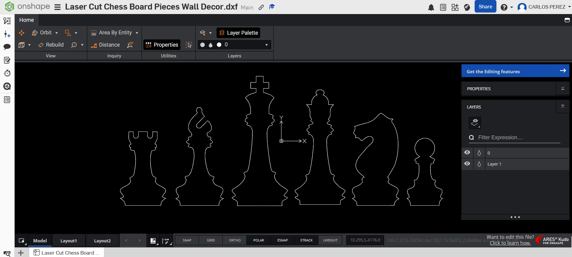
Create a 2D design using CAD software like AutoCAD or Fusion 360. Export the drawing in .dxf format for compatibility with the Flow software suite.
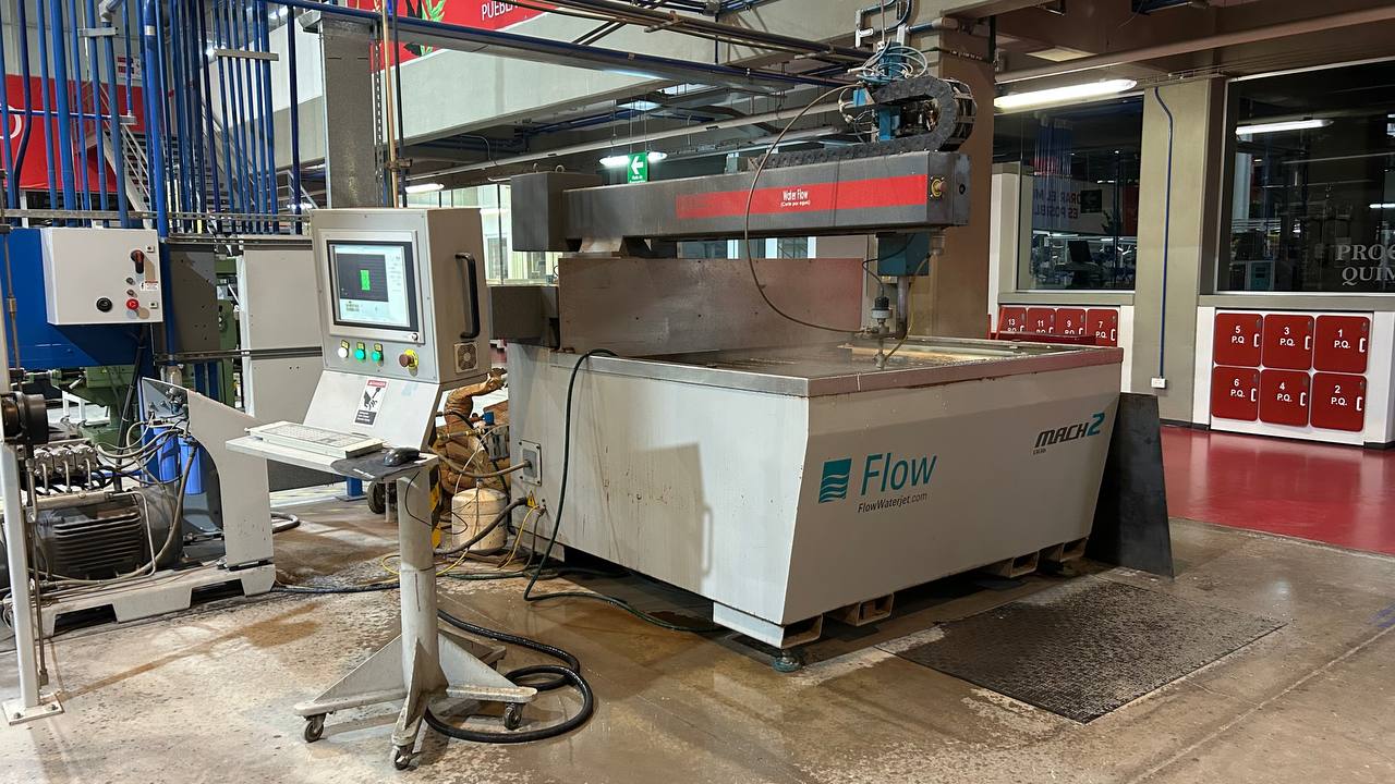
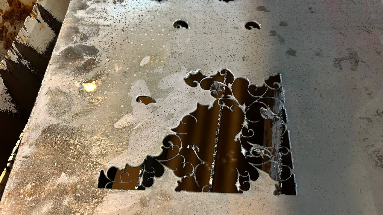
For the manufacture of the components, an ultra-referenced waterjet cutting system from the Flow brand was used, specifically the Mach 2 model. This process was selected due to its ability to make high precision cuts without generating heat affected zones (ZAC), thus preserving the mechanical and structural properties of the original material.
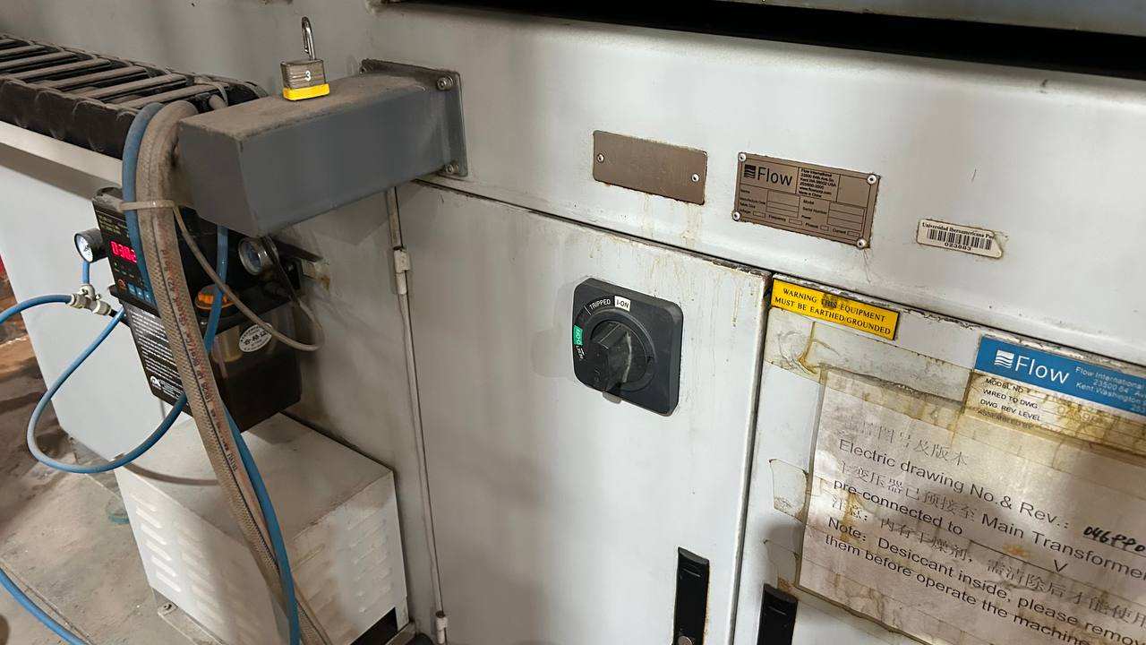
To start the machine operation, turn the main ignition switch (selector knob) from the OFF position to the ON-position. Make sure the switch is securely in the on position before proceeding with the control software.
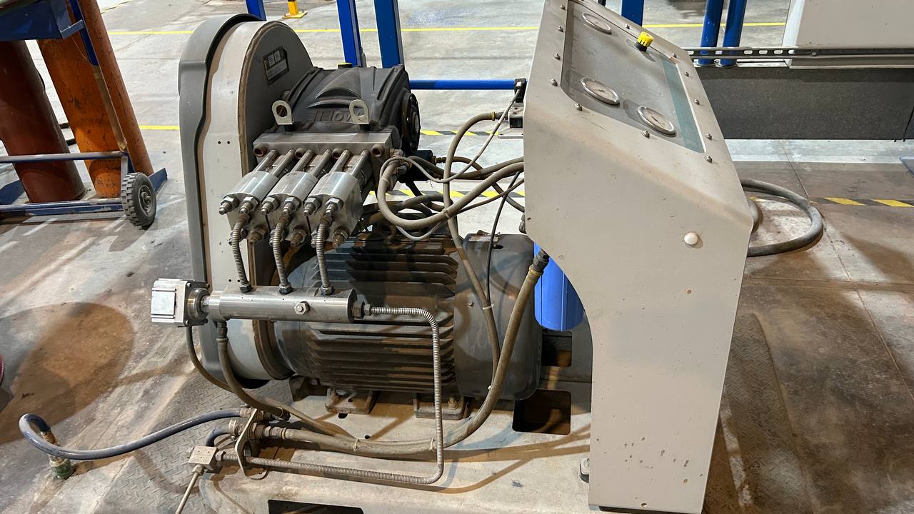
The pressurization subsystem of the Flow Mach 2 machine consists of a high-pressure direct coupling pump and multiple pistons (design based on Flow’s HyPlex pump technology). This component is responsible for converting electrical energy into ultra-high pressure hydraulic power, forcing the passage of water through a millimetre orifice to reach supersonic cutting speeds. As observed on the equipment, the system integrates a powerful synchronous electric motor horizontally coupled to a high-strength stainless steel pump head, complemented by an analog control panel for pressure monitoring and a primary filtration system (blue cartridge) to protect the internal components against suspended particles.
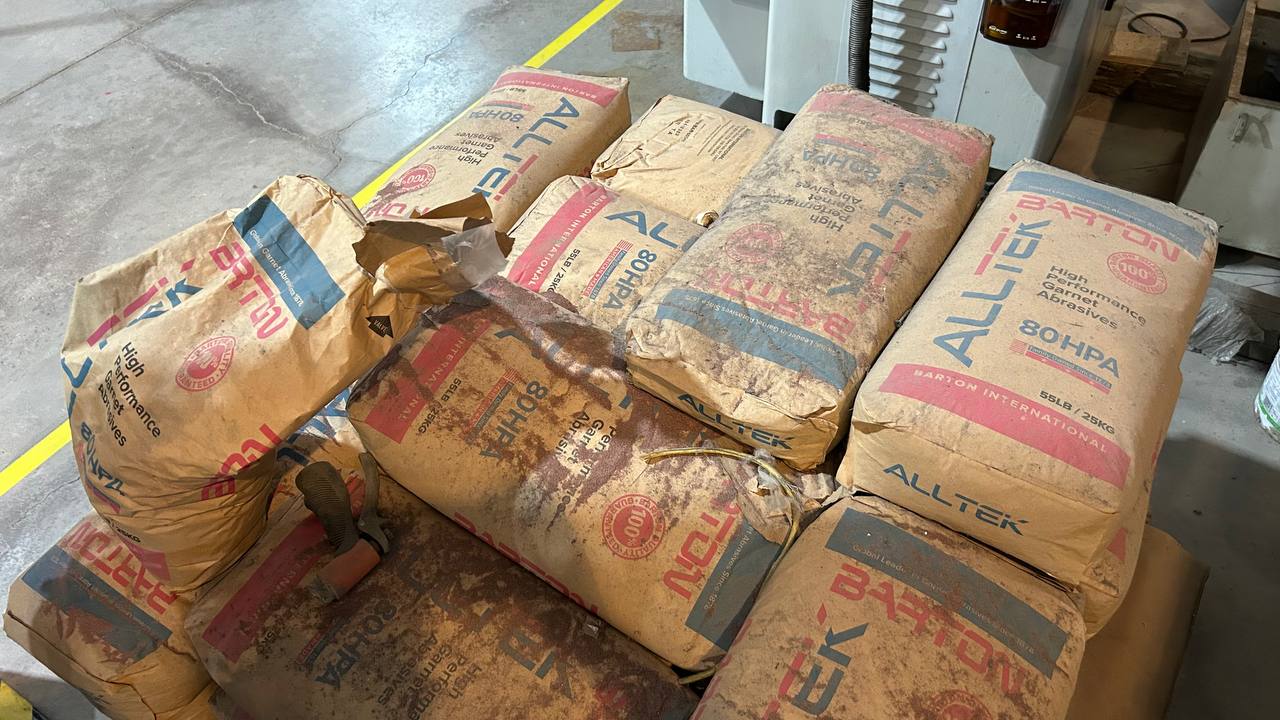
To carry out the cutting of high hardness materials, ultra-high pressure water acts only as the acceleration medium. The real work of removing material is done by a dynamically mixed mineral abrasive in the machine head. This process uses the high-performance abrasive Alltek 80HPA from Barton International. It is not common silica sand (which would harm the machine and the operator’s health). This is Granate (Garnet), a natural mineral of almandine silicate that is characterized by its enormous hardness, density and tenacity.
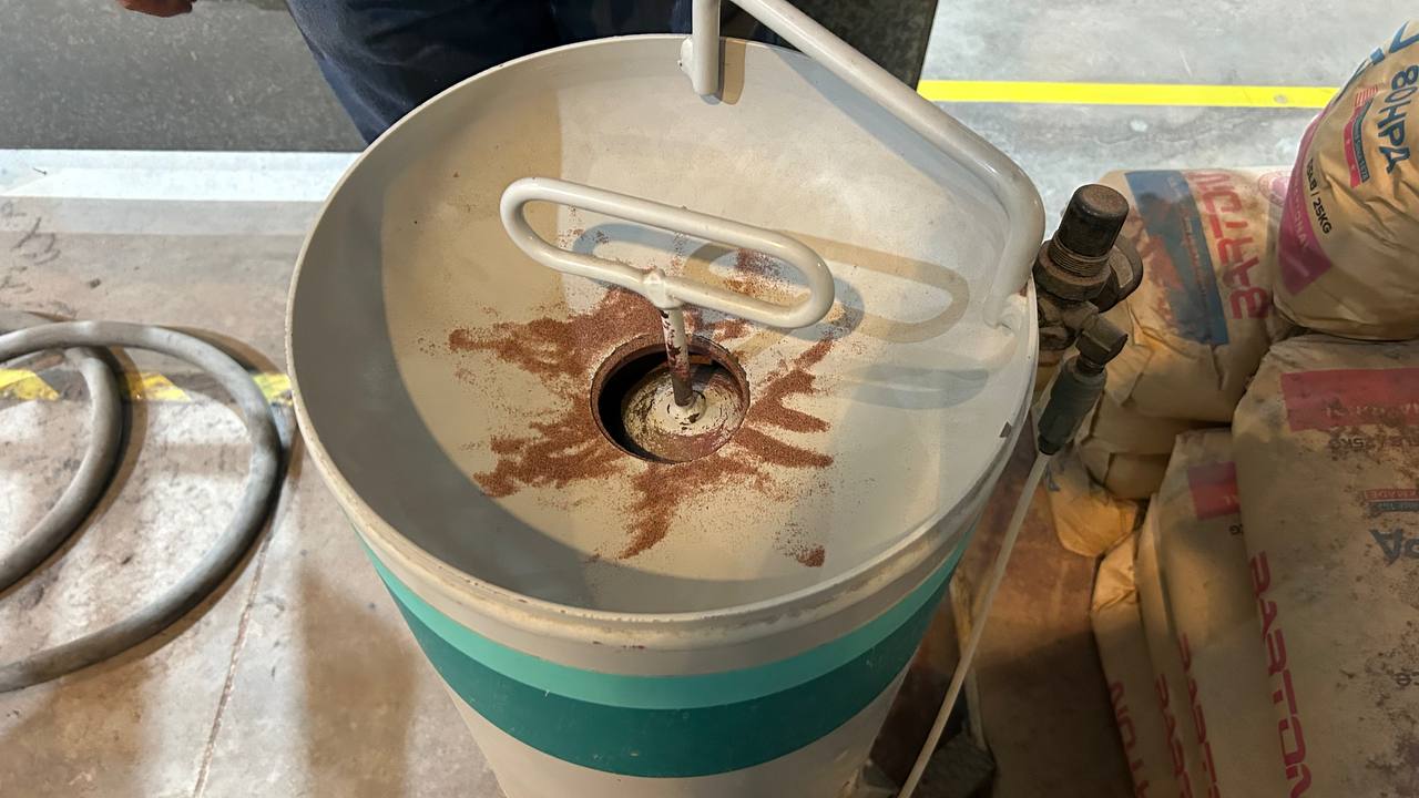
This cylindrical component is the recharging point where the operator dumps the Barton 80HPA grenade packs. Its main function is to ensure a constant, smooth and controlled supply of ore to the cutting head during machining cycles. Around the filling mouth there are traces of the reddish/brown mineral, characteristic of the almandine pomegranate, and in the center is located the manual sealing and pressurization mechanism (T-shaped crank).
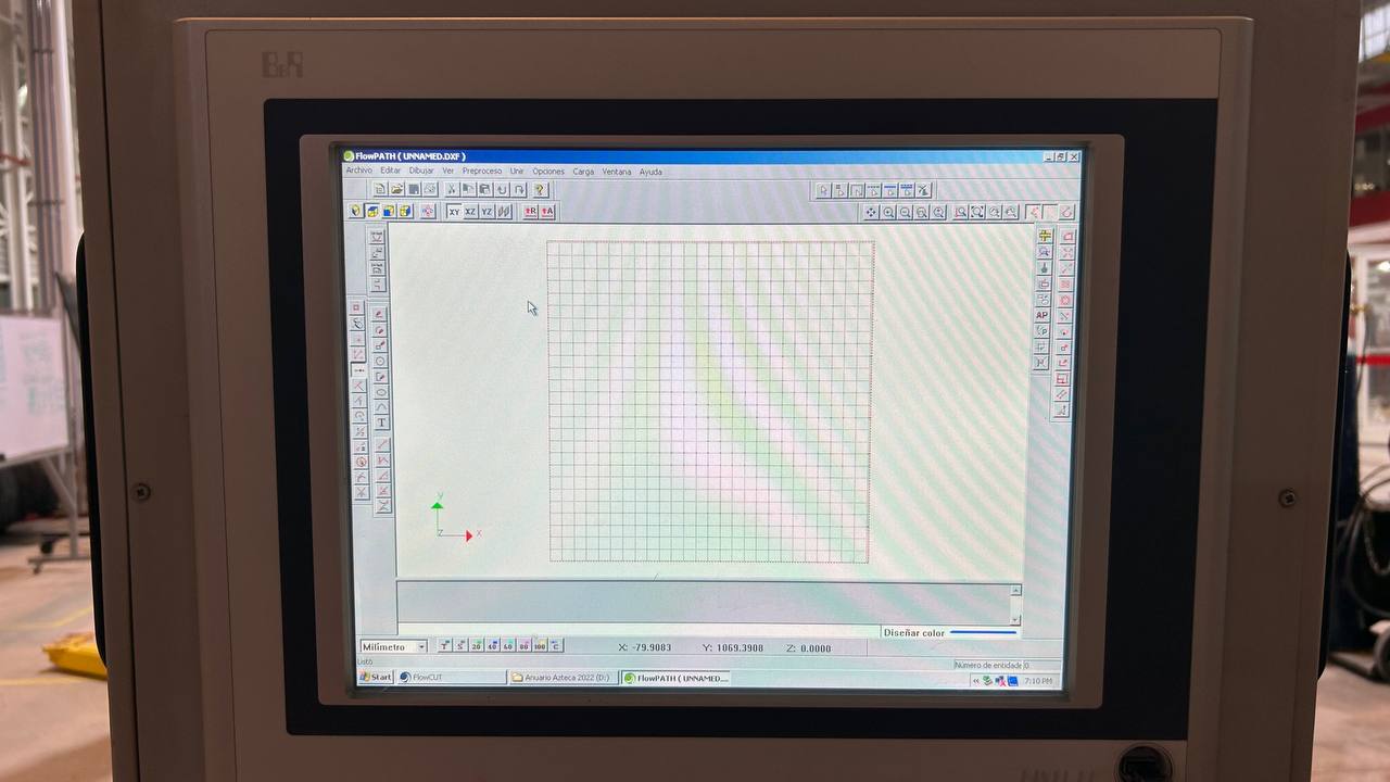
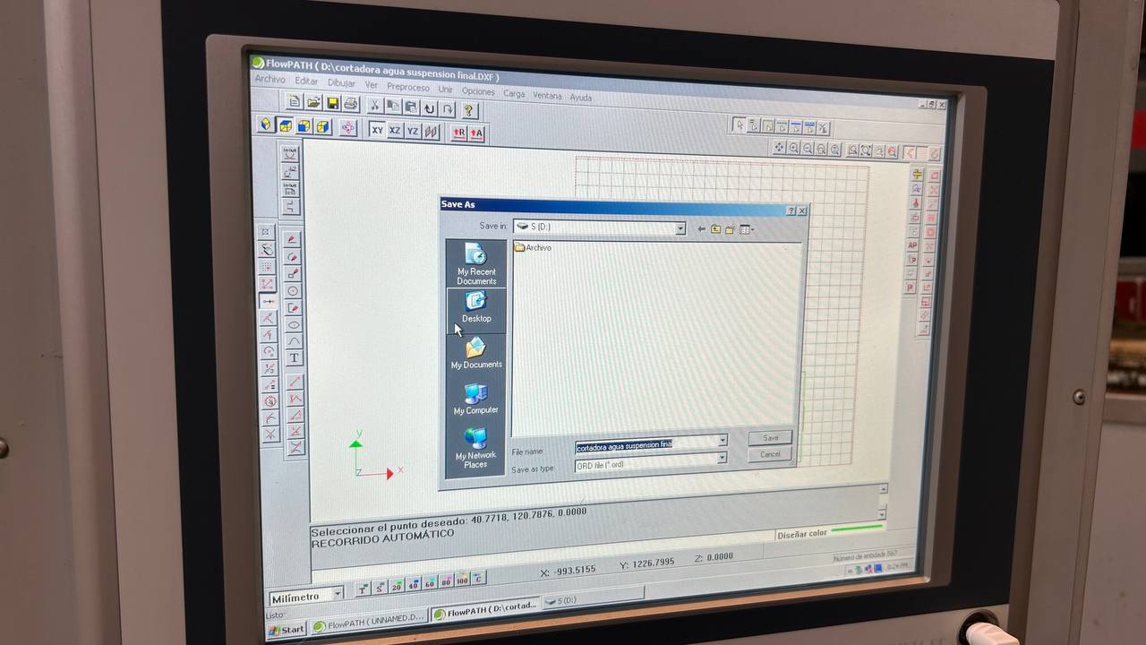
The programming of the machining was carried out on the CNC console using the FlowPATH CAM software, where the vector base design in format was imported. DXF to configure the nozzle trajectories, finish qualities and input and output lines. Finally, the processed geometry was exported with the native extension. ORD, a specialized trajectory file that the FlowCUT control software interprets to coordinate engine movements and the injection of abrasive onto the material.
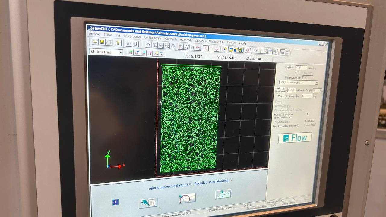
To execute the machining, the file with extension. ORD is loaded into the FlowCUT control software, the native interface that directly manages the physical components of the Flow Mach 2. Within this application, the design path is already fully prepared and structured with its respective progress speeds, tool compensation and initial drilling points. From this moment, the operator uses the platform to calibrate the point of origin (x0, y0) on the material plate, check the levels of Barton 80HPA abrasive in the hopper and activate the high-pressure pump in a coordinated manner (operated at 60,000 PSI) to start the CNC automated cutting process.
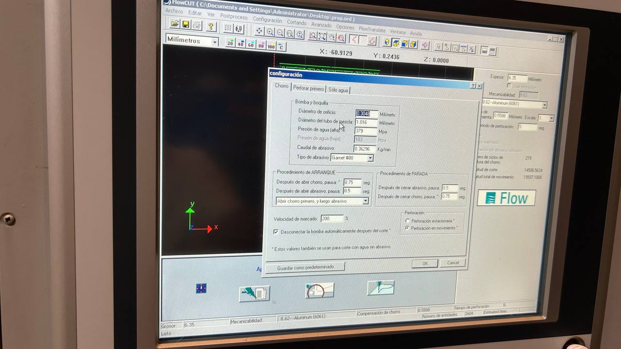
Once the trajectory is loaded into the FlowCUT interface, the software displays three main sections at the bottom of the screen for final validation of the work. The first of these corresponds to the Cut Variable Configuration window, where critical machine parameters are specified such as the diameter of the hole (diamond/sapphire nozzle), the diameter of the focusing tube and the nominal water pressure; since these values are already preset according to the current physical conditions of the head, only validates the information by clicking on the accept button to move sequentially to the next section of the software.
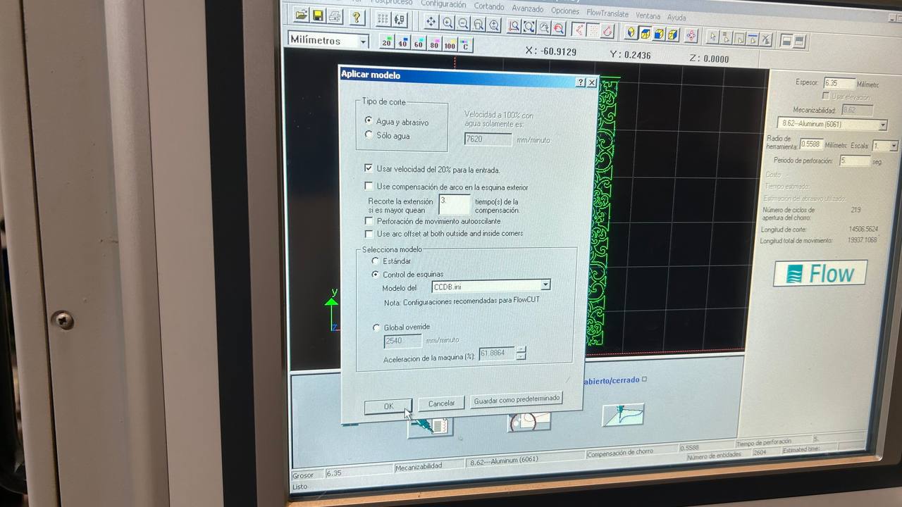
The second section of the interface corresponds to the Model Application window, the module responsible for defining the hydrodynamic nature of the cut according to the properties of the material to be machined. This section selects the operating mode of the head, allowing you to switch between a water and abrasive (Abrasive Waterjet) cycle for high hardness materials such as metals and ceramics, or a pure water only (Pure Waterjet) cycle optimized for soft or porous materials; Once the appropriate cut-off model for the project is determined, the system automatically calculates removal rates before proceeding to the final control panel.
Finally, the third and final section corresponds to the Material Specification window, where the operator manually introduces critical variables such as the exact thickness of the plate and the type of material to be processed (e.g. aluminum, stainless steel or acrylic). Based on these data and the previously validated models, the FlowCUT algorithm performs the final calculation of the machining path, dynamically adjusting the accelerations in each vector to display on screen an accurate estimate of the total time it will take the machine to execute the job.
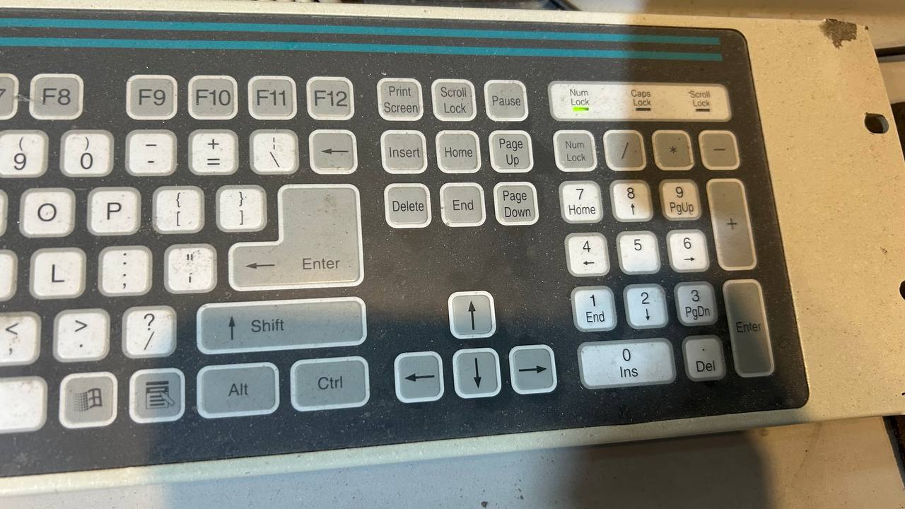
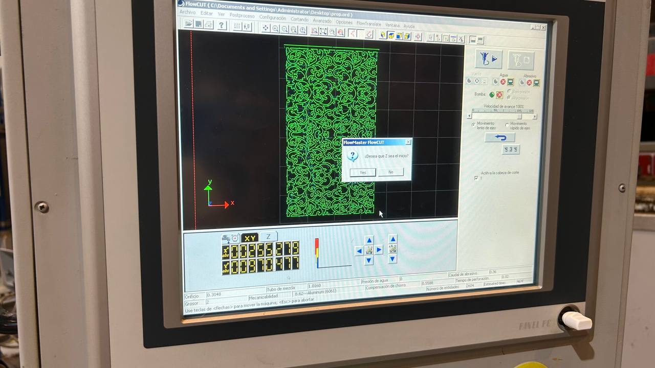
For the manual positioning of the cutting head on the work table, the software allows the movement of the Cartesian axes both through the virtual controllers of the interface and by means of the physical keyboard of the system, being this last modality the one selected for questions of ergonomics and control in the workshop. In this way, the translation on the horizontal plane (X, Y axes) is carried out intuitively using the direction arrows (left, right, forward and backward), while the height adjustment of the nozzle on the vertical axis (Z-axis) is controlled precisely by the forward and backward keys of the page (Page Up for the rise and Page Down for the fall of the head).
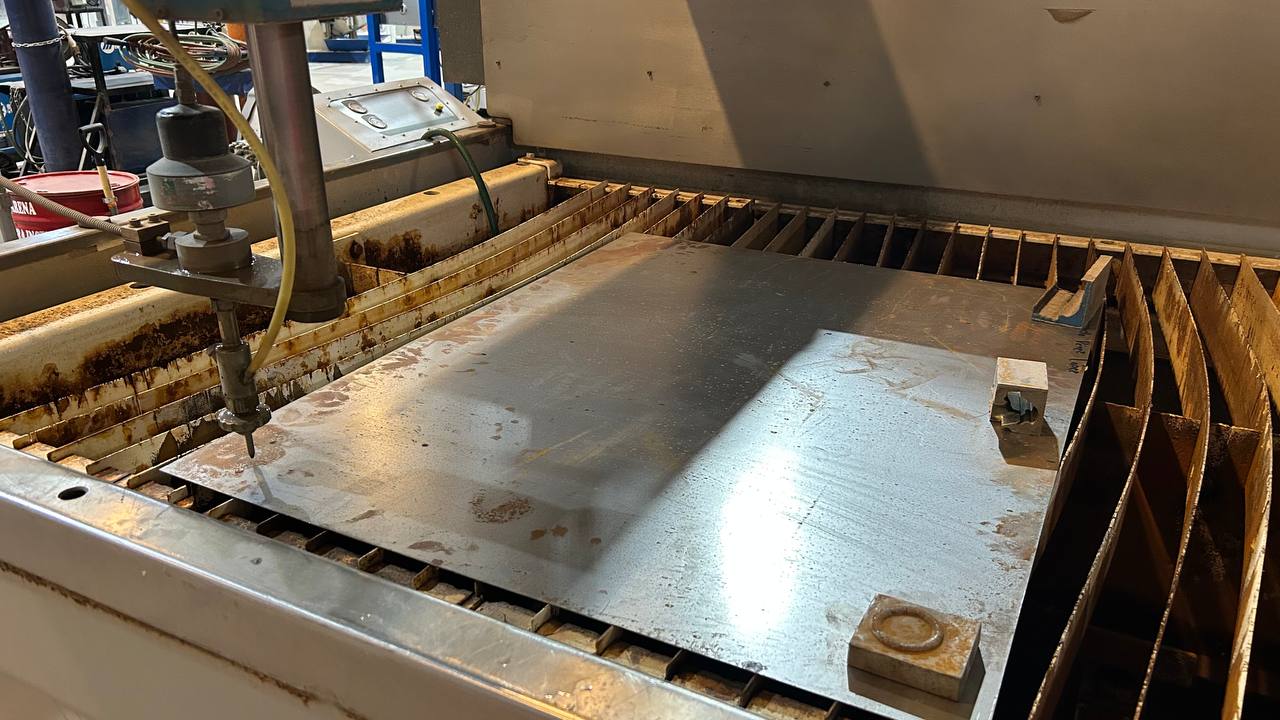
As in any CNC manufacturing process, the critical step before starting machining is to establish the origin of machine coordinates (x0, y0, z0). Once this reference point or "zero piece" is fixed, the material is placed and secured on the grid table; with the plate secured, the file of trajectories with extension. ORD loaded, the optimized cutting path and physical parameters validated on the interface, the system is fully prepared to execute the cutting cycle in an automated and safe way.
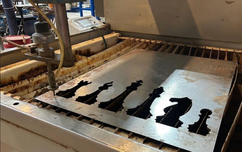
In the audiovisual record you can see the operational power of this manufacturing system. Due to the pressure and speed magnitudes with which the head works, it is essential to emphasize the implementation of the corresponding industrial safety protocols. As a strict safety recommendation, the use of hearing protection is required, since the high-pressure pump and jet shock generate very high noise levels. It is also mandatory to use safety glasses to protect the eyes against water splashes and abrasive particles (granate) that are projected during the process of penetrating and cutting the material.
Create a 2D design using CAD software like AutoCAD or Fusion 360. Export the drawing in .dxf format for compatibility with the Flow software suite.
Post-Cutting: Sandblasting Refinement
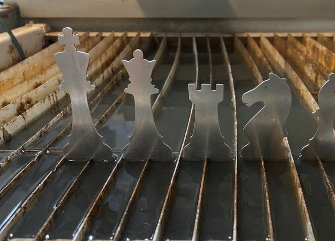
After cutting, the metal had rust and oxide layers. I used a sandblasting machine to propel fine abrasive material at high speed. This process restored the clean appearance and prepared the surface for further processing.
Conclusion
Working with the Flow Mach 2 1313B was an insightful experience into industrial manufacturing. I learned to plan toolpaths, operate high-pressure equipment safely, and use post-processing to refine a final product.