1. What is System Integration?
System Integration is the process of connecting different subsystems or technological components into a single, cohesive architecture that functions as a unified system. Its main goal is to ensure that independent elements —whether hardware, software, or both— work together in a coordinated manner to perform complex tasks that they could not achieve individually. This involves establishing communication between modules, ensuring interface compatibility, and designing centralized or distributed control logic. In DragonTrack, we integrate sensors, actuators, custom PCBs, and mechanical structures to achieve autonomous and efficient ball collection.
2. My Final System: DragonTrack
DragonTrack is an autonomous robotic ball-collector designed to efficiently locate, track, and collect balls in a designated environment. The system consists of a custom mechanical structure manufactured using digital fabrication methods (3D printing + CNC machining), optimized transmission mechanisms, and a microcontroller-based control architecture. The goal is to create an agile, robust mobile robot that automates the tedious task of ball retrieval through synchronized locomotion and an intelligent capture system.
3.1 Mechanical Components
| Item | Details | Quantity |
|---|---|---|
| 3D Printed Parts | Brackets, motor mounts, custom intake geometries | Assorted |
| CNC Machined Elements | Structural chassis panels, base plates | ( ) |
| Fasteners | M3/M4 screws, nuts, spacers for assembly | Assorted |
| Transmission Components | Gears, pulleys, or belts | ( ) |
| Wheels / Tracks | Mobile robot locomotion | ( ) |
3.2 External Electronics
| Component | Quantity |
|---|---|
| Locomotion Motors (DC / Continuous Servos) | ( ) units |
| Collection Mechanism Motor | ( ) unit |
| Microcontroller (Seeed XIAO RP2350 / ESP32C3) | ( ) |
| Motor Driver Module | ( ) |
| LiPo Battery / Power Source | ( ) |
| Tracking Sensor / Camera Module | ( ) |
| Power Switch | 1 |
| Status Indicator LEDs | ( ) |
3.3 Custom PCB Components
| Component | Specification / Package | Quantity |
|---|---|---|
| Main Controller | Seeed Studio XIAO RP2350 / other | 1 |
| Motor Driver IC / Connectors | ( ) | ( ) |
| Resistors | 220Ω (LEDs), 10kΩ pull-up | ( ) |
| Capacitors | 10µF, 0805 for filtering | ( ) |
| Status LEDs | 5mm or SMD | ( ) |
| Pin Header Connectors | For external motors and sensors | ( ) |
The mechanical design of DragonTrack focuses on a functional, rugged, and agile solution. The structure combines lightweight 3D-printed brackets with durable CNC-machined elements to ensure rigidity and performance. Fully modeled in Fusion 360, the design places the intake mechanism at the front to optimize ball interception, while internal storage capacity is maximized without increasing the robot's physical footprint. Key components such as motor mounts and wheel hubs are reinforced to withstand loads during continuous driving.
The chassis is structured with interlocking assemblies to allow adjustments, upgrades, and quick access to electronics. The custom transmission system optimizes torque-to-speed ratio, allowing the robot to maintain steady movement while the collection roller operates efficiently. Onboard power and microcontroller integration ensure smooth, controlled operation.
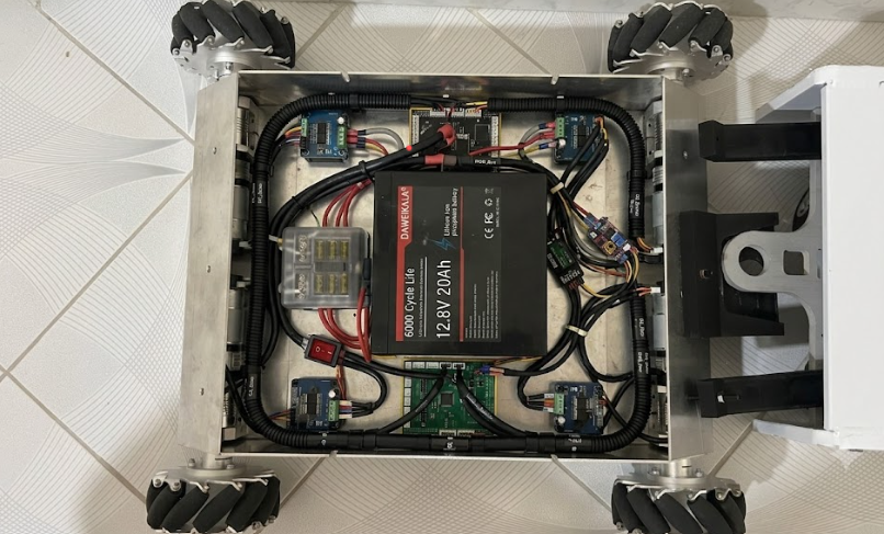
Project Packaging & Cable Management
Efficient space optimization and robust wire routing are critical for the reliability of high-current mobile platforms. This section outlines the strategic planning, execution, and architectural trade-offs of the system's internal packaging.
1. Planning Phase (How it was Planned)
The primary objective was to house a heavy 12.8V 20Ah LiFePO4 battery, four independent motor drivers, power distribution blocks, and control electronics within a compact aluminum chassis. The planning prioritized:
- Weight Distribution: Centering the massive battery core to maintain an optimal center of gravity for the omnidirectional Mecanum wheels.
- Electromagnetic Interference (EMI) Isolation: Separating high-current DC motor lines from sensitive logic signals.
- Serviceability: Ensuring individual components (like fuses or specific motor drivers) could be replaced without dismantling the entire wire harness.
2. Execution Phase (How it was Done)
The physical implementation translated the conceptual layout into a clean, industrial-grade electronics bay:
- Perimeter Routing: Main power supply lines and motor control cables were bundled and routed along the interior walls of the aluminum chassis using corrugated conduit loom.
- Securing Infrastructure: Heavy-duty adhesive tie mounts and zip ties were strategically anchored to prevent wire migration during high-vibration maneuvers.
- Modularization: A centralized fuse box and dedicated master switch were positioned immediately adjacent to the battery, minimizing the length of unprotected high-current leads.
3. Trade-offs: Advantages & Disadvantages
Refining the packaging layout yielded significant improvements in system integrity, though it introduced specific engineering constraints:
| Advantages | Disadvantages |
|---|---|
| High Reliability: Eliminates the risk of loose cables getting caught in moving mechanical parts or local gears. | Increased Assembly Time: Precision routing, cutting loom to size, and anchoring requires significant upfront manual labor. |
| Thermal Efficiency: Keeping the center clear maximizes airflow around the central battery core and heat-generating components. | Reduced Flexibility: Swapping a component or adding new sensors requires cutting zip ties and re-threading the conduit harness. |
| Rapid Troubleshooting: Clean color-coding and structured paths allow for immediate visual inspection during faults. | Tight Tolerances: Rigid routing leaves very little slack, demanding highly accurate initial wire-length calculations. |
The drive motors and collection mechanism are controlled using an intelligent embedded program. Motors respond to sensor inputs to execute smooth turning, acceleration, and tracking maneuvers, dynamically adjusting speeds to ensure reliable ball capture.
Tracking & Detection Functionality
DragonTrack uses tracking logic to start, pause, or adjust its collection routine. The robot processes input data to locate balls and commands the drive system to align with the target. Detecting a ball initiates a capture sequence, while losing the target safely pauses the robot or triggers a scanning rotation.
Possible Issues
- Motor Driver Connection: Incorrect wiring causes no movement or excessive current draw.
- Tracking Sensor Disconnection: Malfunction leads to infinite spinning or failure to recognize objects.
- Power Instability: Voltage drops that reset the microcontroller during motor stalls.
- Signal Noise: EMI near logic lines causing erratic movements or false sensor readings.
Microcontroller Code
// DragonTrack System Control Code
#include <Arduino.h>

// Define Motor Control Pins (Adjust to match your custom PCB routing)
const int motorLeftPWM = ( );
const int motorLeftDir = ( );
const int motorRightPWM = ( );
const int motorRightDir = ( );
const int intakeMotorPWM = ( );

// Define Sensor Inputs
const int trackingSensorPin = ( );
int sensorState = 0;

void setup() {
    pinMode(motorLeftPWM, OUTPUT);
    pinMode(motorLeftDir, OUTPUT);
    pinMode(motorRightPWM, OUTPUT);
    pinMode(motorRightDir, OUTPUT);
    pinMode(intakeMotorPWM, OUTPUT);
    pinMode(trackingSensorPin, INPUT);
    Serial.begin(115200);
}

void loop() {
    sensorState = digitalRead(trackingSensorPin);

    if (sensorState == HIGH) {
        // Target detected: Engage intake and move forward
        digitalWrite(motorLeftDir, HIGH);
        digitalWrite(motorRightDir, HIGH);
        analogWrite(motorLeftPWM, 180);
        analogWrite(motorRightPWM, 180);
        analogWrite(intakeMotorPWM, 255);
        Serial.println("Target Tracked - Collecting...");
    } else {
        // No target: Spin safely in place to scan environment
        digitalWrite(motorLeftDir, HIGH);
        digitalWrite(motorRightDir, LOW);
        analogWrite(motorLeftPWM, 120);
        analogWrite(motorRightPWM, 120);
        analogWrite(intakeMotorPWM, 0);
        Serial.println("Scanning for targets...");
    }
    delay(50);
}
Tracking Optimization: Basic binary detection logic can be improved with algorithms handling variable angles and distances. Refining this requires analyzing latency and mechanical response to achieve fluid interception paths.
During the testing phase, system functionality is validated by assessing each component individually: locomotion motors, drivers, intake mechanism response, and storage alignment. The tracking sensor interface is monitored across different ambient lighting levels. Custom mechanical transmissions undergo cyclic stress tests, and the chassis is tested on various floor textures to ensure vibration does not loosen critical connections. Soft-start acceleration profiles are implemented to mitigate current spikes.
Overall packaging and balance ensure that heavy components like batteries are centrally located to maintain a stable center of gravity. Final integration tests confirm that DragonTrack operates as a unified platform: autonomous navigation, target tracking, and reliable collection.
[X] Product-oriented design with clean finishes, post-processed geometries and protected sensors.
The most important lesson learned: mechanical design is fundamentally linked to electronics performance. Calculating proper transmission gear ratios and calibrating motor speeds for precise maneuvers was critical. For future students, I highly recommend focusing on power distribution and structural rigidity from day one, performing iterative bench tests on sub-circuits, and being prepared to redesign mounting brackets. Robot balance, cable routing, and electrical noise management are key to achieving a reliable, professional system.
Completing the final system integration of DragonTrack allowed me to synthesize practical engineering skills from industrial design, digital fabrication, and embedded electronics. I gained advanced insights into motor control (acceleration profiling, torque regulation), sensor noise management, and data filtering for reliable real-time tracking. On the mechanical side, designing for assembly with tight tolerances using 3D printing and CNC machining was an enriching challenge. From an electrical perspective, designing a robust power bus that isolates logic from high-current noise proved invaluable. This project demonstrated that small physical adjustments drastically alter overall performance, reinforcing the value of rigorous testing and iterative prototyping.
Copyright 2026 — Carlos Perez · Creative Commons Attribution Non Commercial