Project Context: Why a Skateboard?
Living in a city like Puebla, "last-mile" transportation is a constant challenge. Short distances are too long to walk but too congested for a car.
I chose an Electric Skateboard because it combines efficiency, portability, and fun. It’s a tool for personal growth that fits inside a classroom.
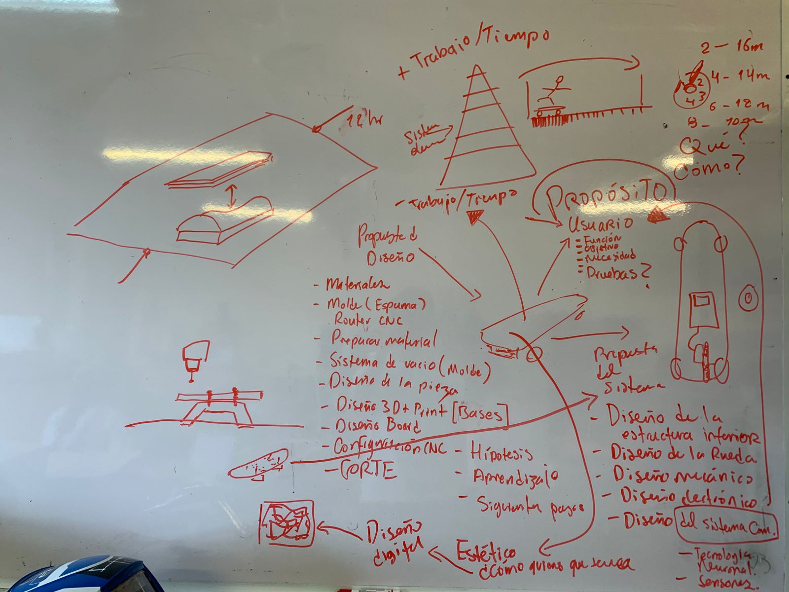
[ CLEAN COPY: WHITEBOARD DELIBERATION ]
Strategic Roadmap
To ensure a functional result, I have divided the development into two critical phases:
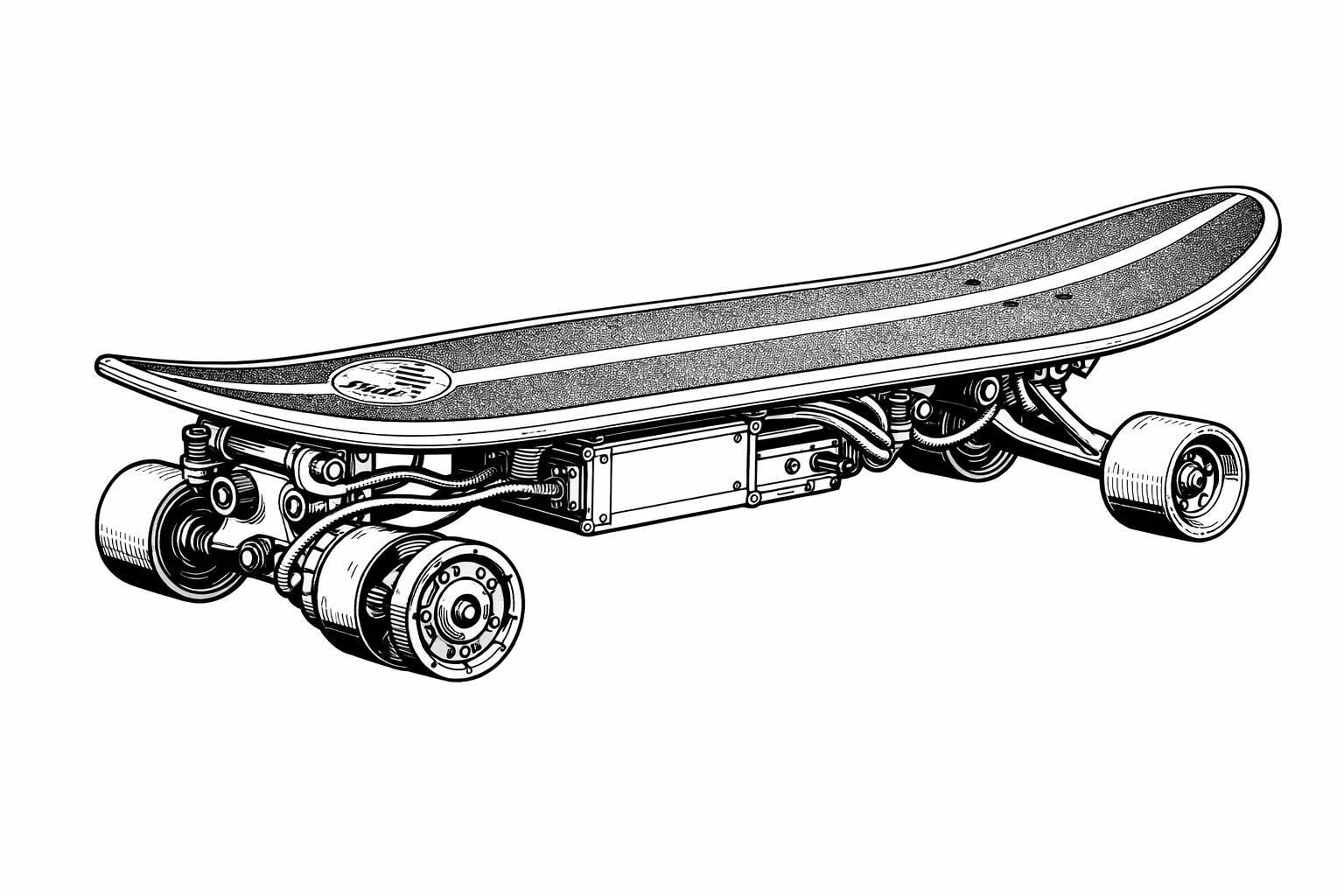
The Drive System
Focusing on the Electronics & Control. The goal is to establish a reliable wireless link between a hand-held remote and the motor controllers (ESC). This phase ensures the "heart" of the board works before moving to structural work.
- Wireless Signal Testing (NRF24 or ESP-NOW)
- Motor Driver Integration (TB67 / VESC)
- Battery Management Safety
Custom Deck Fabrication
Once the electronics are stable, I will fabricate the deck from scratch using Fab Lab resources. This isn't just about cutting wood; it's about material science and structural design.
- Large-scale CNC (ShopBot) for the core
- Vacuum pressing composite layers
- 3D Printed enclosures for aesthetics
The Decision Process
Remote Controlled Car
Fun to build, but limited practical use. It felt more like a toy than a tool for personal growth.
Electric Longboard
Interdisciplinary: Requires CNC (deck), 3D printing (enclosures), Electronics, and Molding.
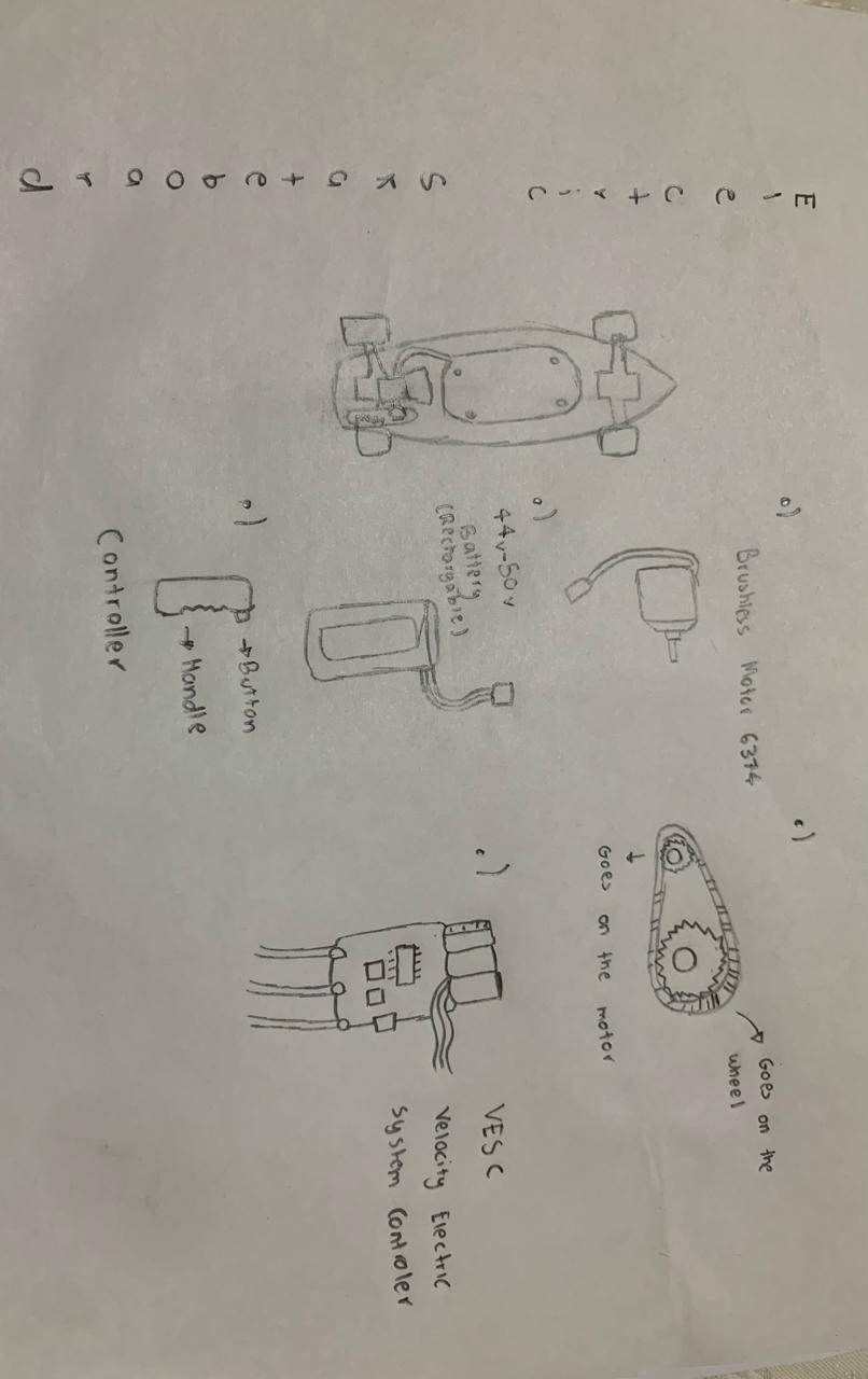
System Rundown: Final Project Components
The following hardware has been selected to meet the high-performance requirements of my electric skateboard project, focusing on reliability and power efficiency.
Speed Control
- FLIPSKY Mini FSESC6.7
- 70A continuous current
- Aluminum Anodized Heat Sink
- Based on VESC 6.6 PRO

Propulsion
- 5065 BLDC Outrunner
- 270KV High Torque
- Sensored for smooth starts
- 6-12S Voltage Range

Power Source
- 36V 10S3P Li-ion Pack
- 18650 Rechargeable Cells
- Integrated BMS & Charger
- Customized for EV use

Communication
- XIAO ESP32-C3
- WiFi & BLE 5.0 Connectivity
- Ultra-small Form Factor
- Custom Remote Interface

Technical References & Inspiration
My foundation comes from analyzing mechanical transmission systems. I am currently focusing on belt-drive alignment and XIAO RP2350 integration for the remote system.
"The goal is to replace off-the-shelf components with Fab Lab manufactured parts whenever possible."
[ REF: MECHANICAL ALIGNMENT ANALYSIS ]
Project Development Roadmap
Following a systematic approach to build the ultimate last-mile transportation tool.
STEP 01: System Design & Architecture
Conceptualization of the electrical system, defining pinouts for the XIAO RP2350, and creating the master wiring diagram for both remote and receiver.
STEP 02: PCB Fabrication & Assembly
Milling custom PCBs using the MonoFab, followed by precision soldering of the TB67 drivers, NRF24 modules, and surface-mount components.
STEP 03: Communication & Control Programming
Developing the wireless link protocol between the remote and the board. Calibrating the joystick response and implementing failsafe routines for motor safety.
STEP 04: Mechanical Integration
Mounting the system onto a test skateboard or the custom-milled ShopBot deck. Installing motor mounts, belt drives, and 3D-printed enclosures.
STEP 05: Field Testing & Deployment
Real-world stress tests in daily commuting scenarios to verify battery range, signal stability, and structural integrity of the final deck.