
What is Digital Embroidery?
Digital embroidery is a computerized manufacturing process where a specialized CNC machine translates vector artwork into coordinates, commands, and precise stitch pathways. Unlike traditional printing, embroidery utilizes thread layers to create physical relief textures on fabric. For this wildcard week, I focused on learning the open-source software InkStitch (an extension for Inkscape) to digitize my designs and generate path commands for a commercial Brother CNC Embroidery Machine.
SELECT MANUFACTURING PHASE.
[ PHASE 1: DIGITAL VECTOR STITCH DIGITIZATION ]
Extension Installation
Download the official InkStitch software extension and add its component libraries directly to your local Inkscape installation directory extension folder.
DOWNLOAD INKSTITCH
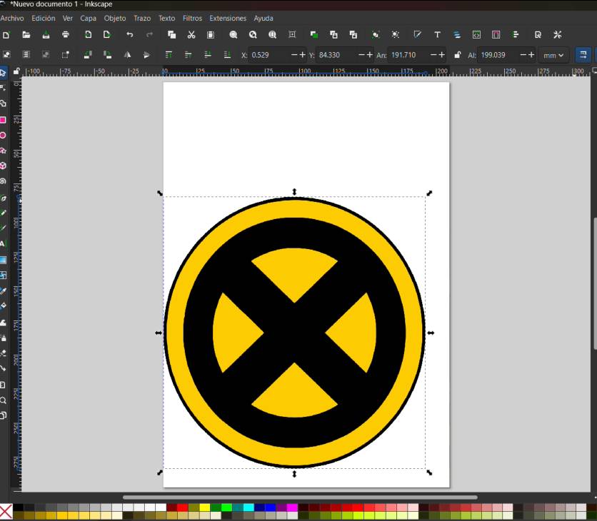
Artwork Importation
Locate the specific logo design or high-resolution graphic asset you intend to embroider and import it directly onto your open canvas workspace within Inkscape.
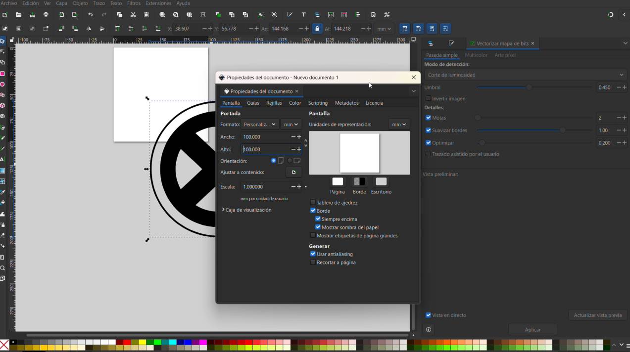
Canvas Work Area Setup
Configure your document page layout properties and set the workspace dimensions exactly to 100 mm x 100 mm to align with physical machine hoop parameters.
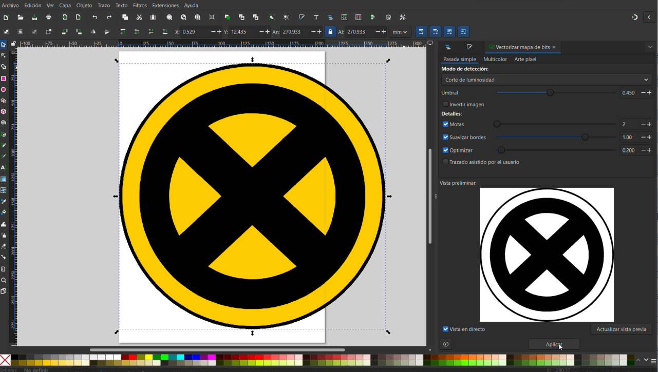
Image Vectorization
Execute a 'Trace Bitmap' operation sequence on your raw imported artwork file to convert pixels into clean, scalable vector geometric paths.
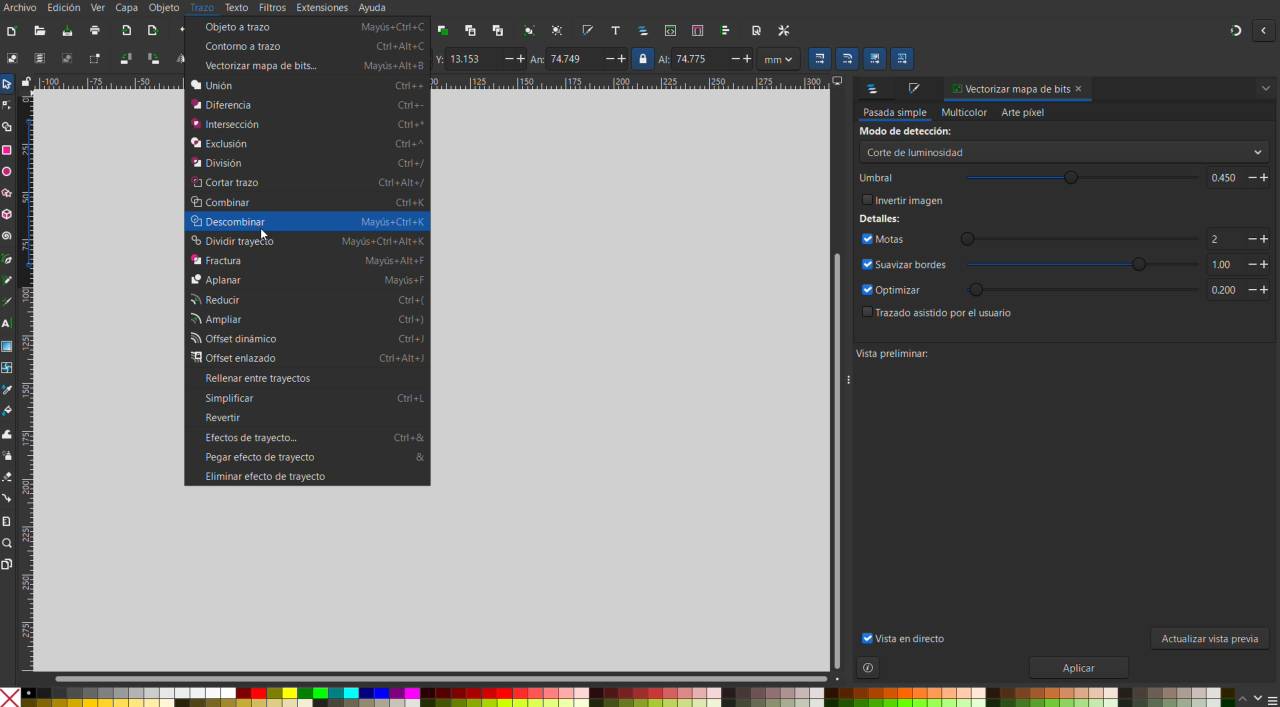
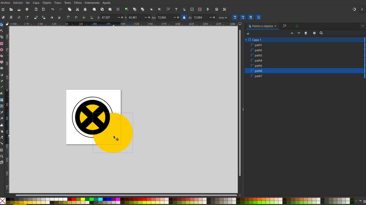
Break Apart Geometry
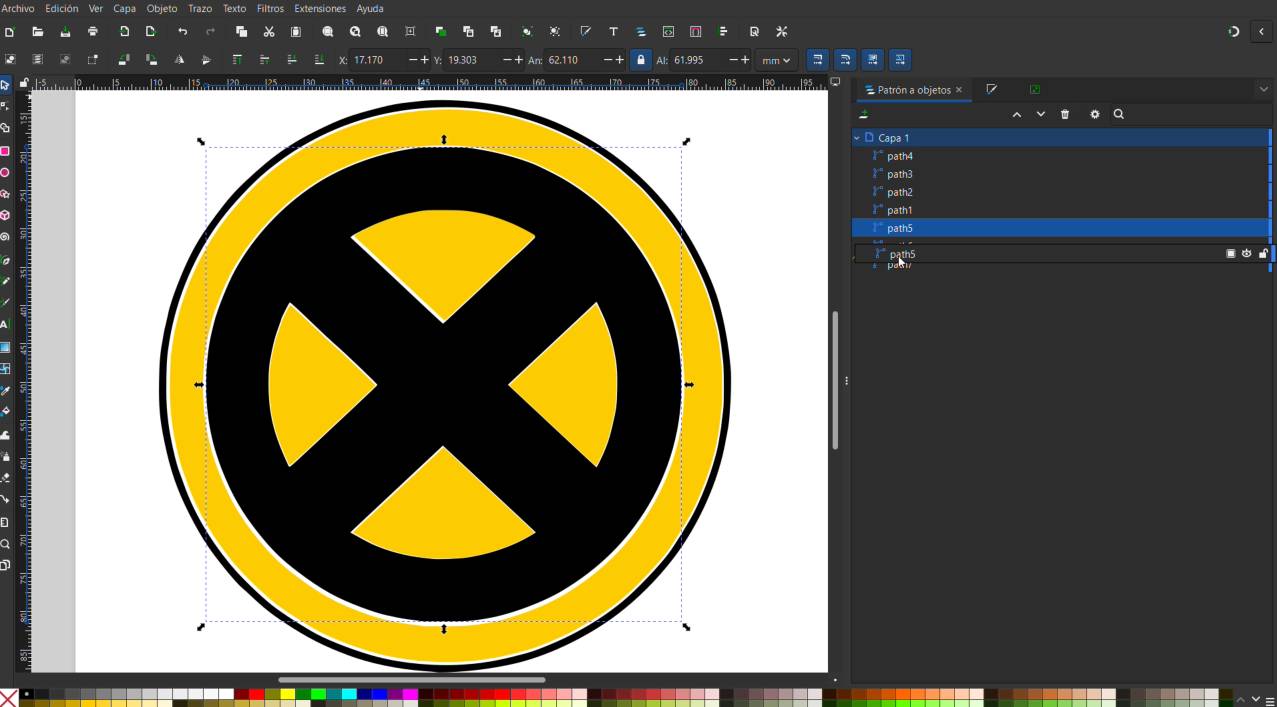
Select your finalized vectorized graphic group, navigate up to the main 'Path' dropdown option in the top application menu bar, and execute the 'Break Apart' action.
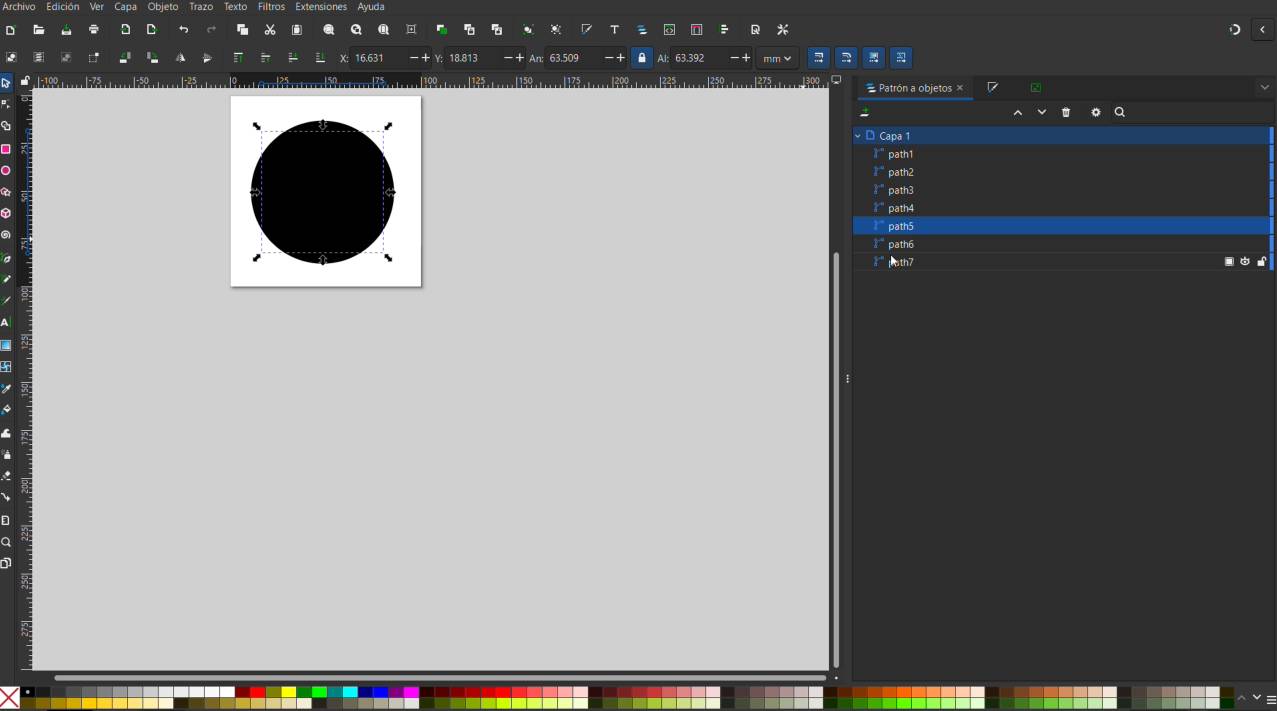
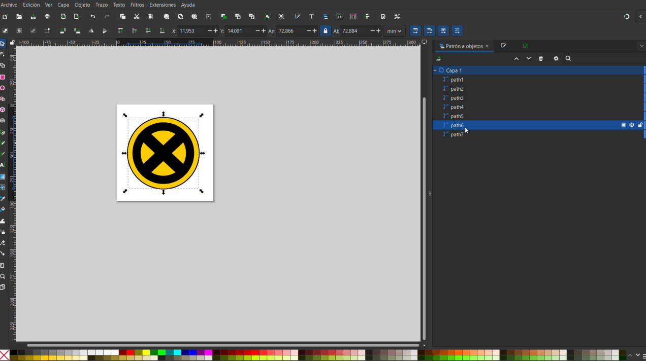
Object Layers Inspection
Open the 'Objects' dock docking menu panel to visualize the complete structural list of generated vector layers containing all individual pieces of the drawing design.
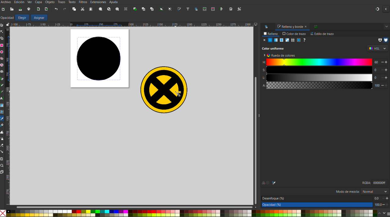
Color Assignment
Select the corresponding generated layout sub-layers one by one and apply the precise final color palette choice to structure your design blocks.
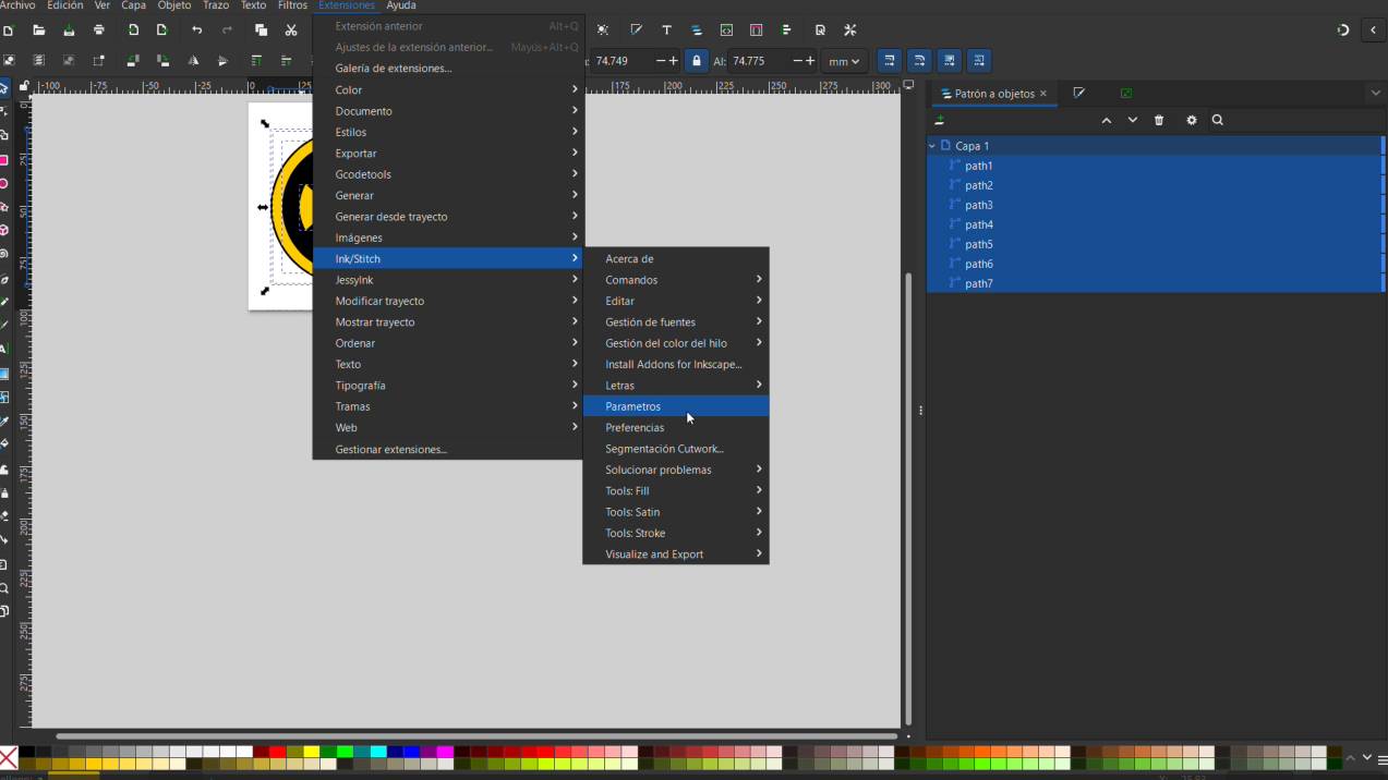
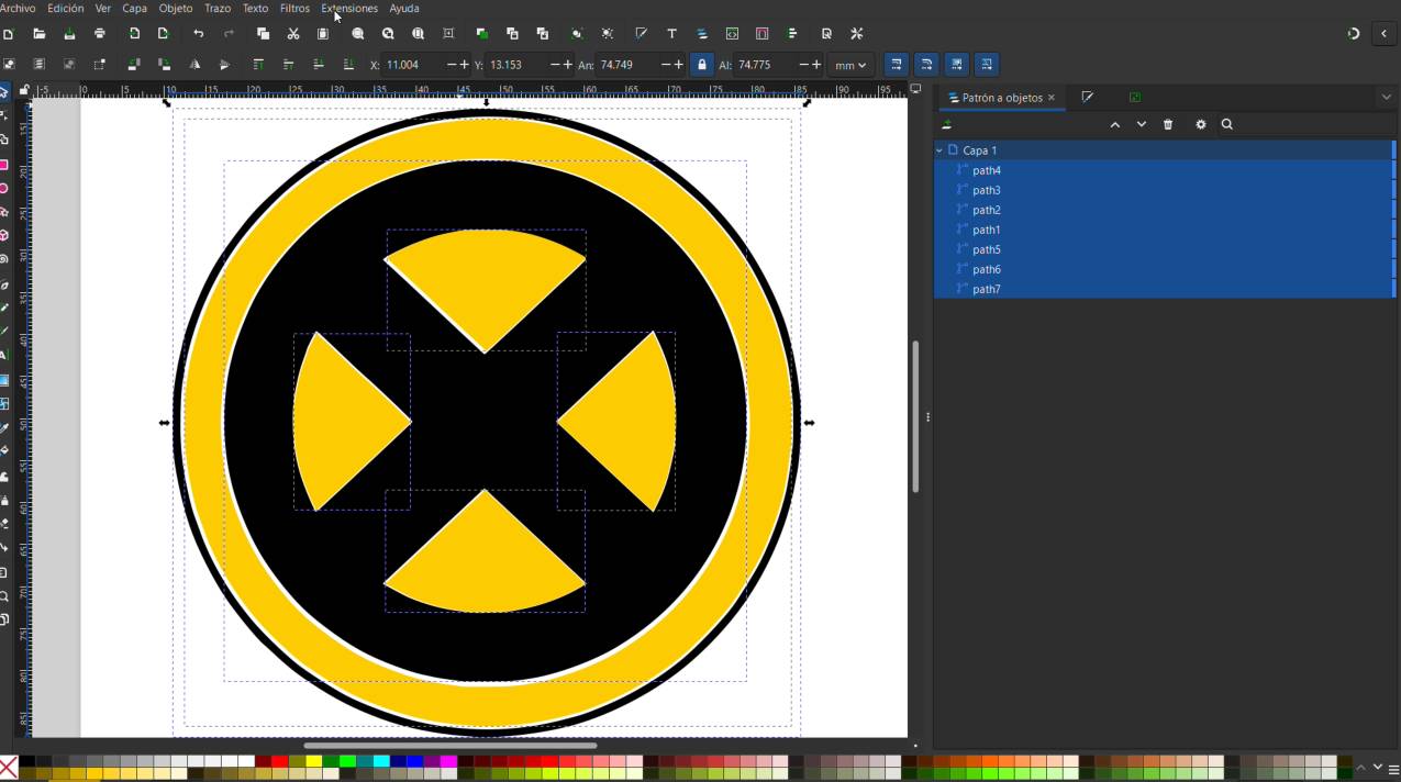
InkStitch Parameters Initialization
Select all of your structural layers together, open the top application 'Extensions' menu dropdown, find the 'InkStitch' sub-directory selection, and click on 'Params'.
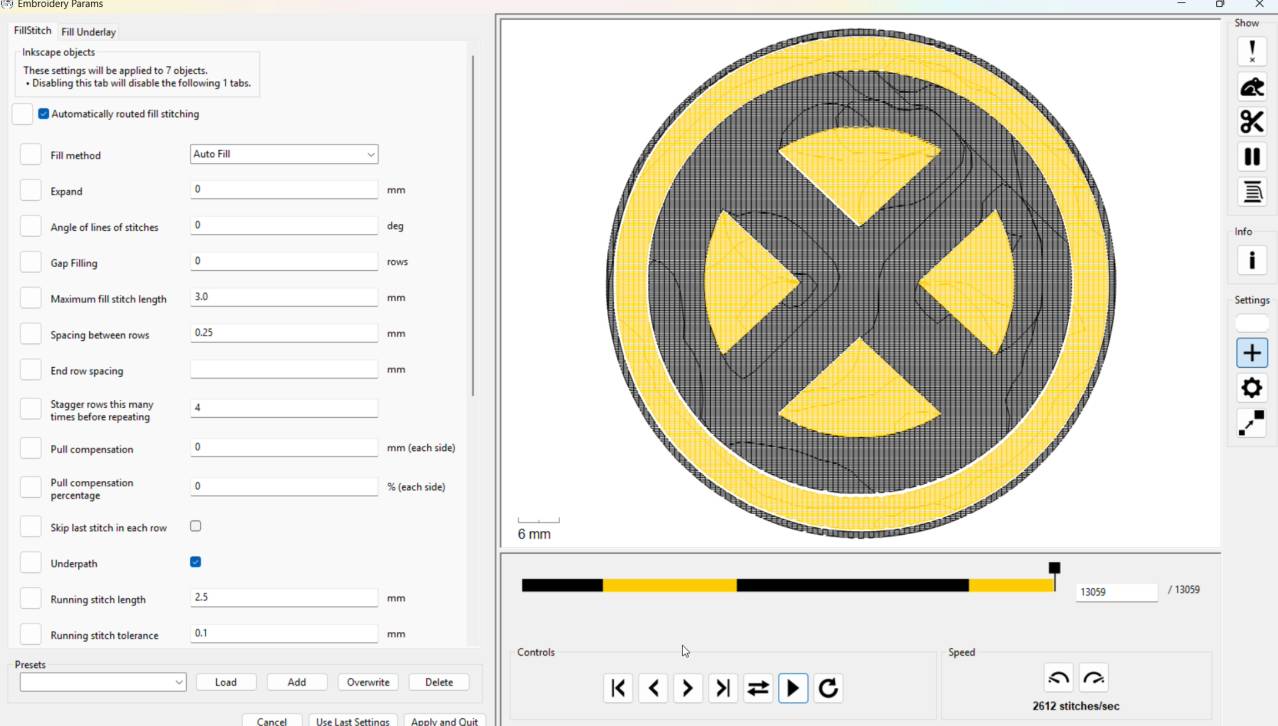
Stitch Path Simulation
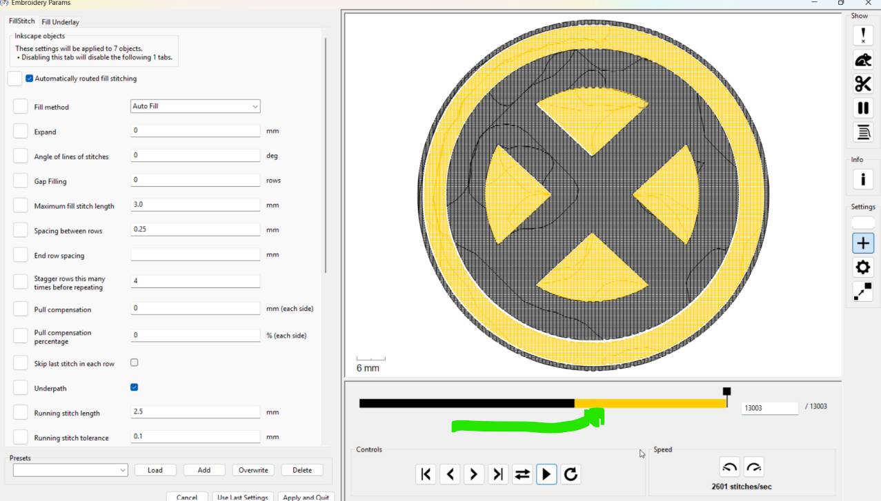
Within the new configuration panel setup window that opens, press the interactive playback engine button to generate a real-time tracking timelapse simulation to check for errors.
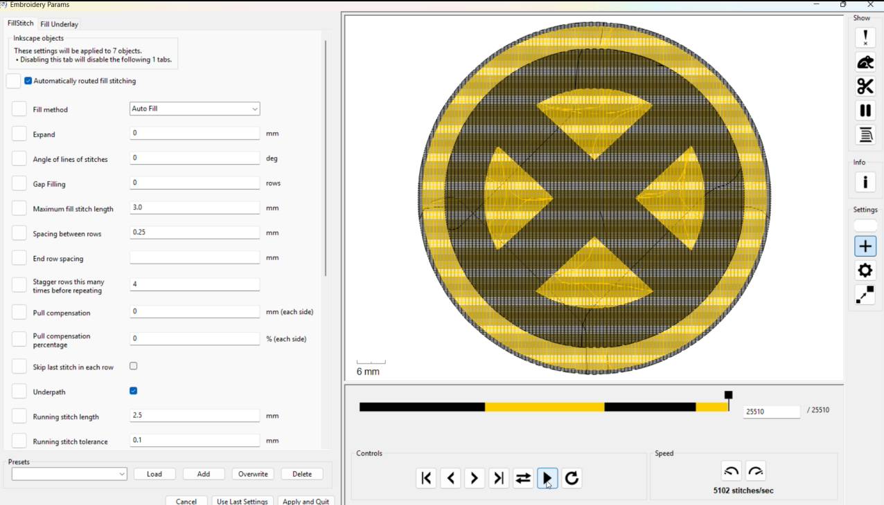
Layer Stack Density Overlap Hazard
In my specific project layout, the fabric fill layers were stacking directly on top of each other. This high-density thickness must be corrected to protect the machine needle structure from snapping under stress.
Isolating Vector Profiles
Return to your main canvas layout workspace, open your structural geometry manager panel, select the second-to-last layer item from the bottom stack, and copy it to your clipboard.
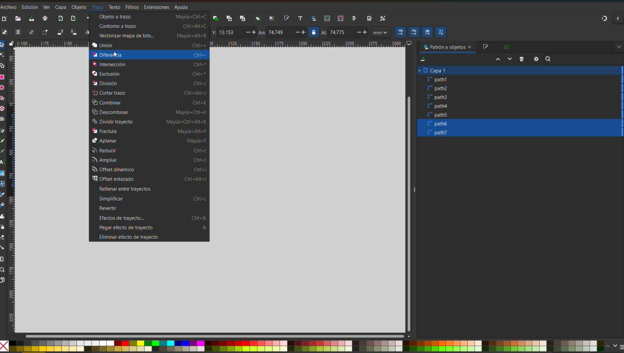
Boolean Difference Operation
Select both the last and second-to-last layer nodes simultaneously, navigate to the top 'Path' menu, and run a 'Difference' operation. This subtracts and crops the hidden stack geometry out entirely, temporarily eating the overlapping section.
Restoring the Reference Matrix
Paste your copied layer vector piece back into its precise original location framework. Repeat this exact boolean path extraction loop with the third-to-last layer, and continue sequentially upward with the rest.
Geometry Breakdown Verification
Once you finish pruning the overlap segments across your vector composition, you can verify that each segment constitutes its own flat, independent mosaic piece.
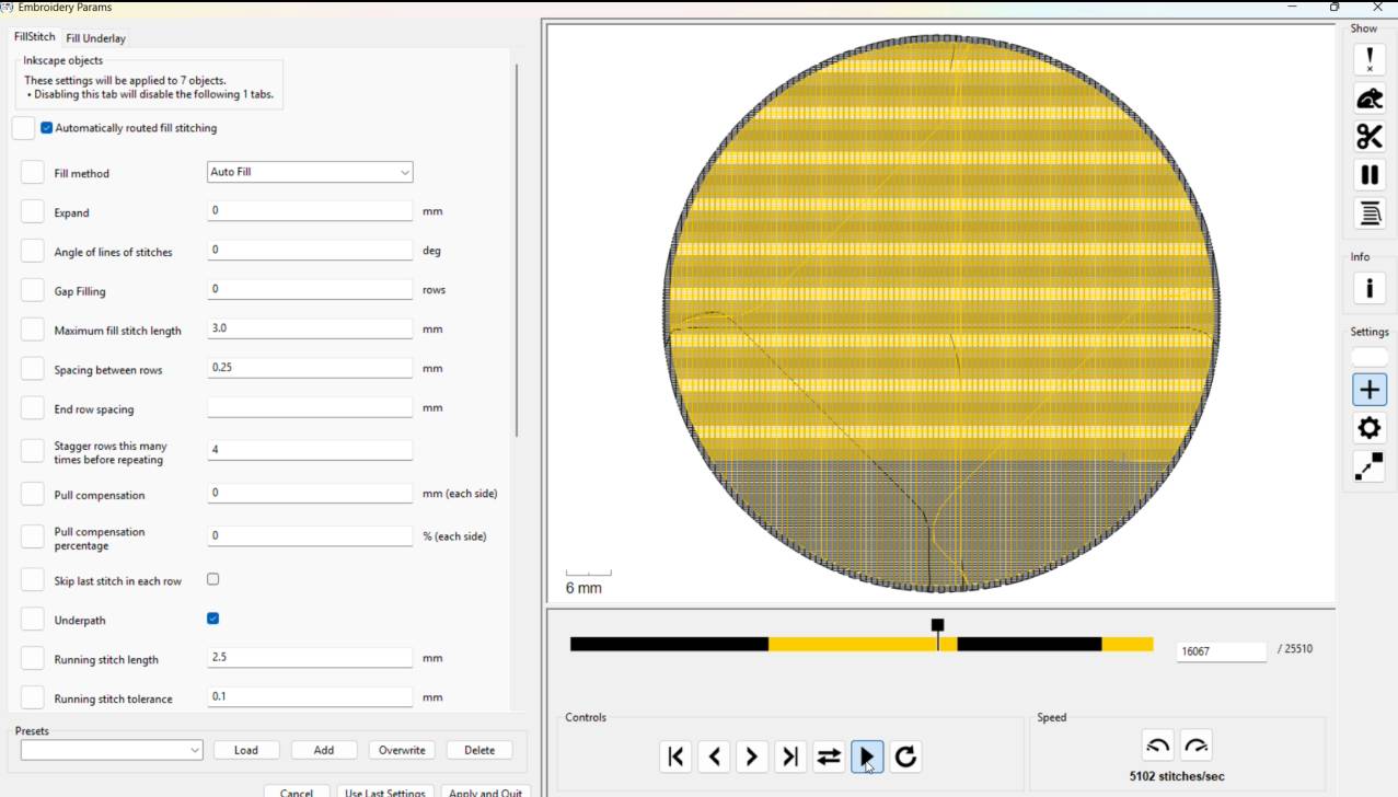
Optimized Pathway Simulation
Open the InkStitch parameters preview tool window once more. If your steps were accurate, the system tracking simulation will confirm that each component pattern stitches independently without bulk layering.
Thread Cycle Sequence Evaluation
Examine the color blocks arrangement timeline at the bottom bar showing toolpath cycles. If the software keeps alternating back and forth between color changes constantly, it will result in an unoptimized, slow production run.
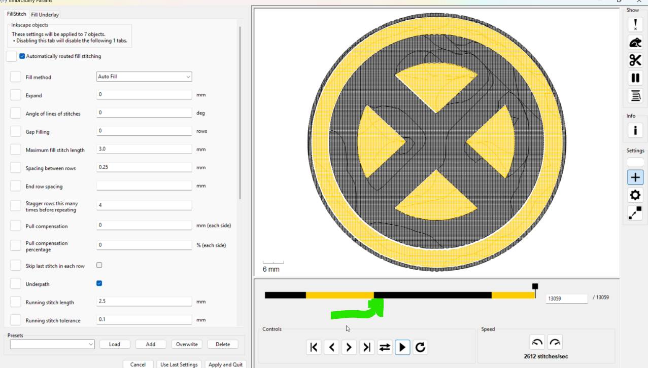
Layer Sequence Sorting
Return to the main Inkscape design viewport layout. Within your layers panel, manually drag and drop your objects so that all paths sharing an identical color are grouped back-to-back.
Reduced Toolpath Thread Changes
Load the InkStitch configuration view panel. You will see that all elements sharing matching thread colors have compiled into a single manufacturing path block, cutting down time-consuming thread swap commands.
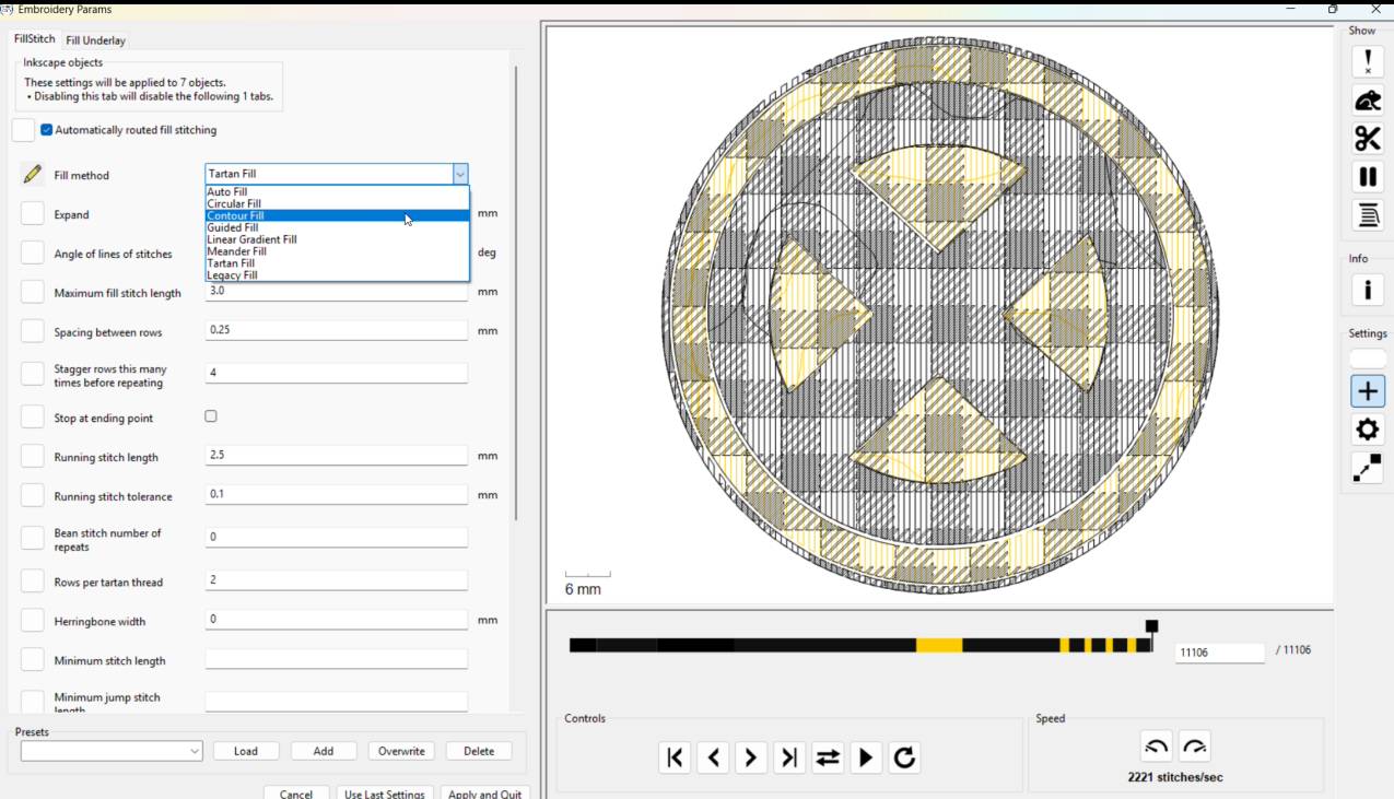
Advanced Stitch Fill Formatting
Utilize the software tools panel to customize stitch properties such as row spacing density and stitch architecture angles. This allows you to easily substitute patterns, such as switching from a satin stitch to a full Tatami grid texture.
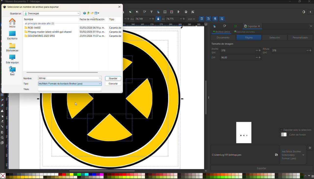
PES Format Export
Save and export your file directory artwork document utilizing the specialized **.PES format extension**. The compiled asset is now fully optimized and ready to be loaded into the Brother embroidery hardware controller unit.
[ PHASE 2: BROTHER CNC HARDWARE OPERATION RUN ]
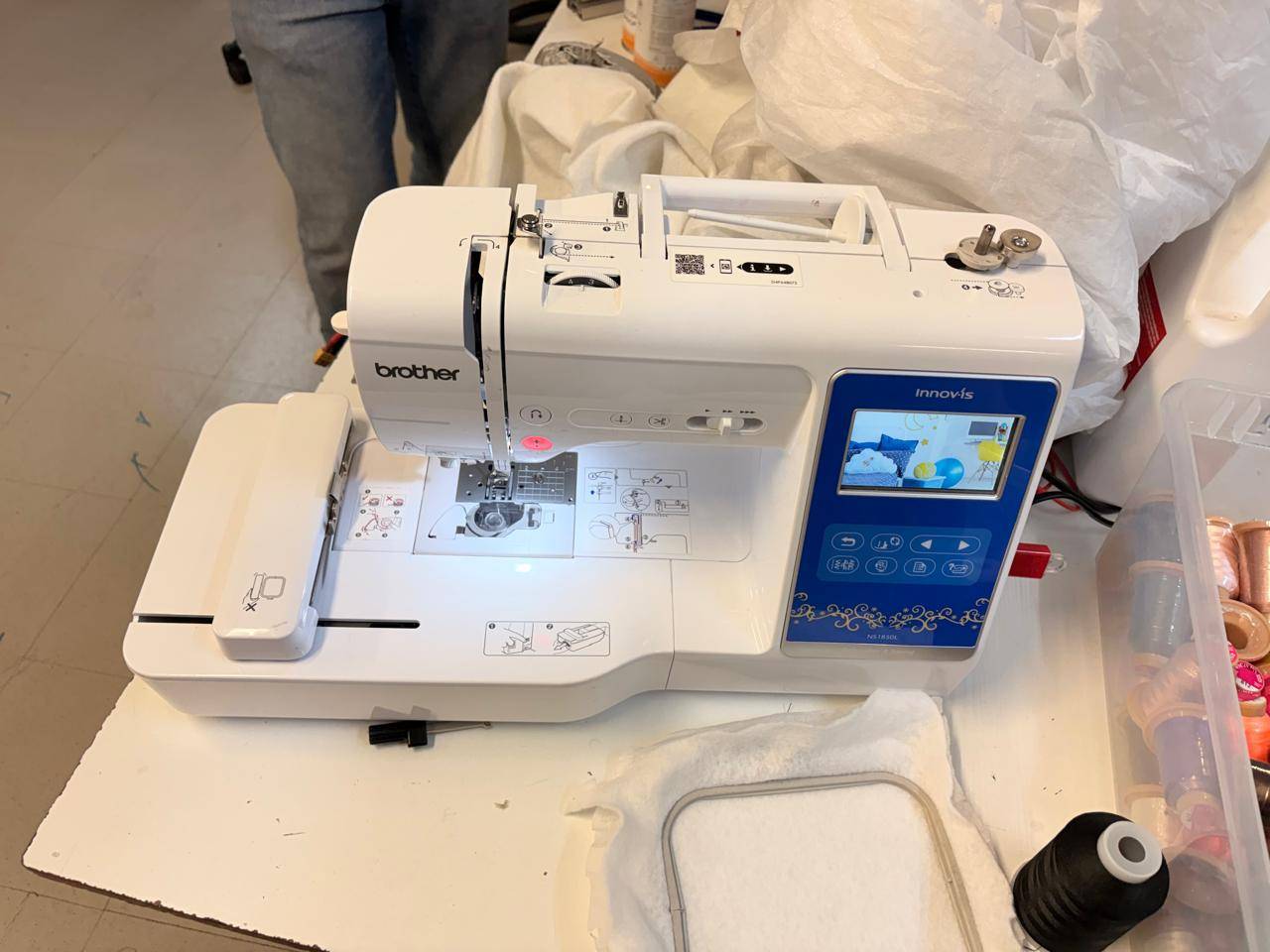
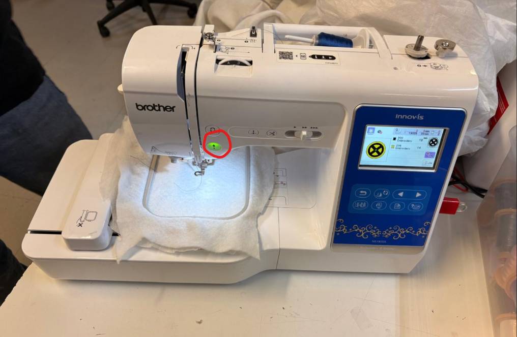
Machine Model Identification
This is the digital manufacturing equipment utilized for the project: a Brother NS1850L embroidery and sewing workstation. Key considerations:
- Needle: Use 130/705 H Embroidery needles (size 75/11 standard).
- Fabric: Most fabrics are compatible; use appropriate stabilizers.
- Thread break: Stop the machine, re-thread, and backtrack the design a few stitches to resume.
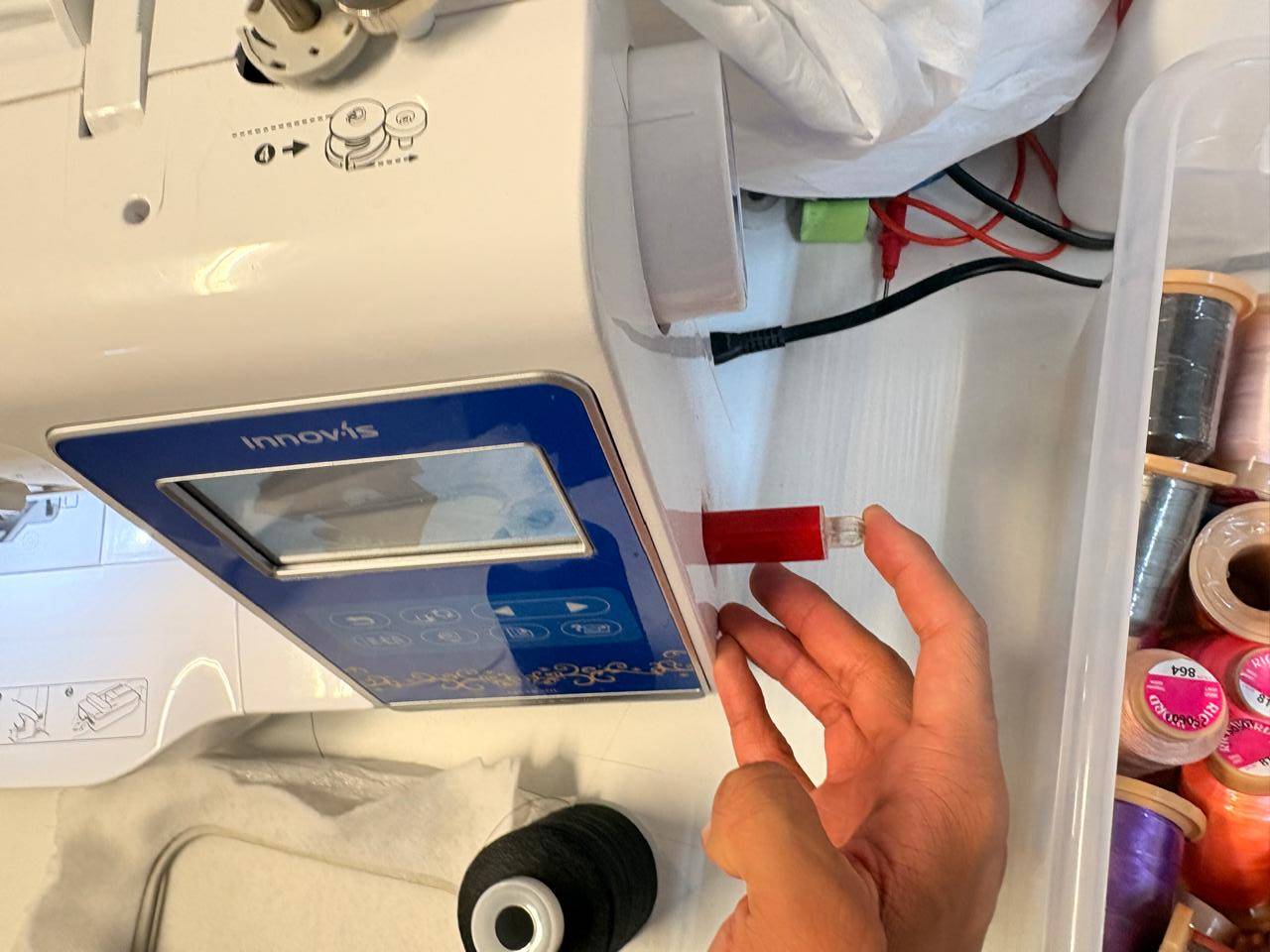
Flash Drive Connection
Insert the USB storage flash drive containing your fully optimized and compiled .PES embroidery file into the machine's hardware port.
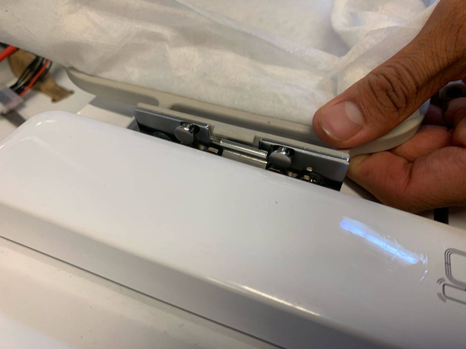
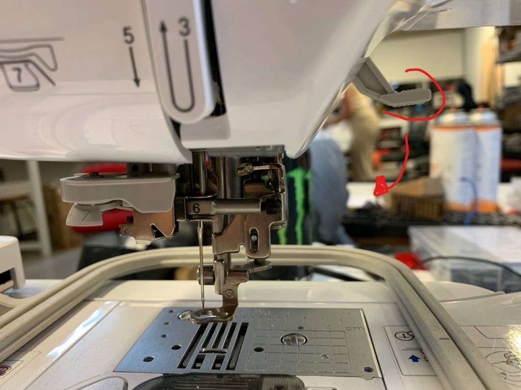
Embroidery Flatbed Prep
Remove the specific auxiliary work unit bed highlighted in the reference drawing to clear the workspace and mount the fabric placement fixtures.
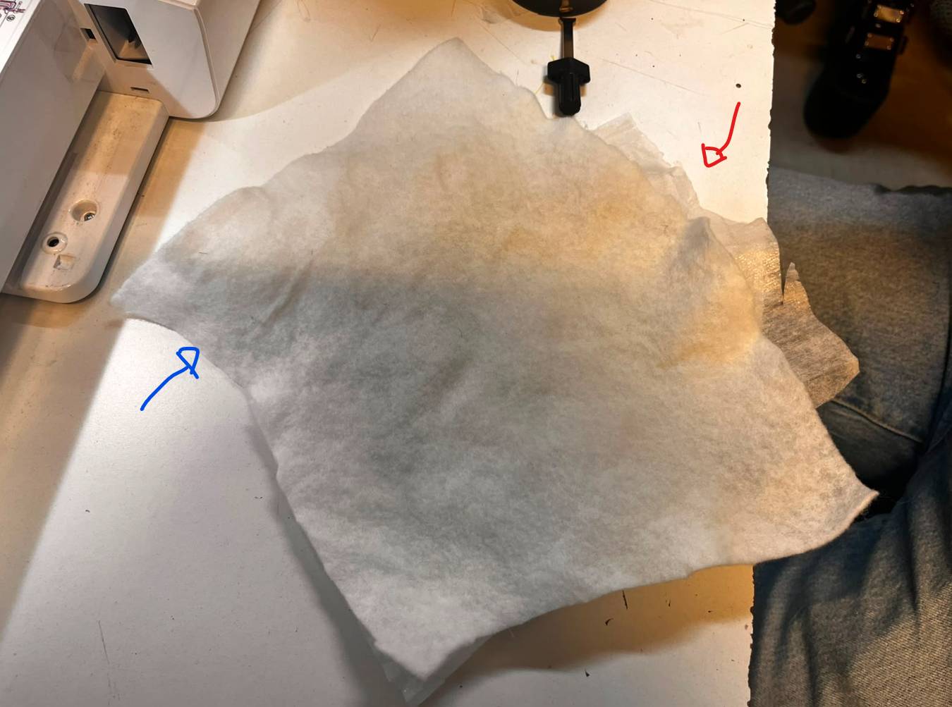
Material Selection
For this specific manufacturing run, we combine two distinct types of fabric matrices to guarantee rigid physical structure and definition.
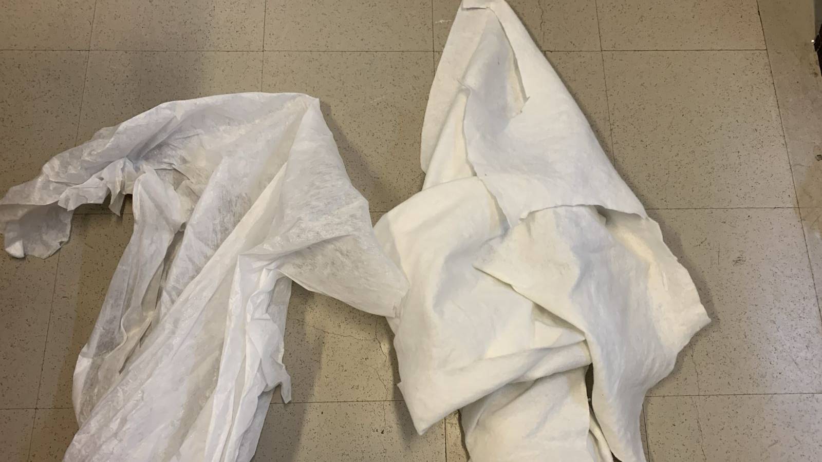
Fabric Layer Stacking
Arrange and stack your fabric materials accurately according to the visual diagram, keeping the thick stock piece on top and the transparent stabilizer backing layered underneath.
Hoop Clamping Action
Place and lock your stacked fabric material tightly between the two separable structural halves of the machine's frame hoop assembly.
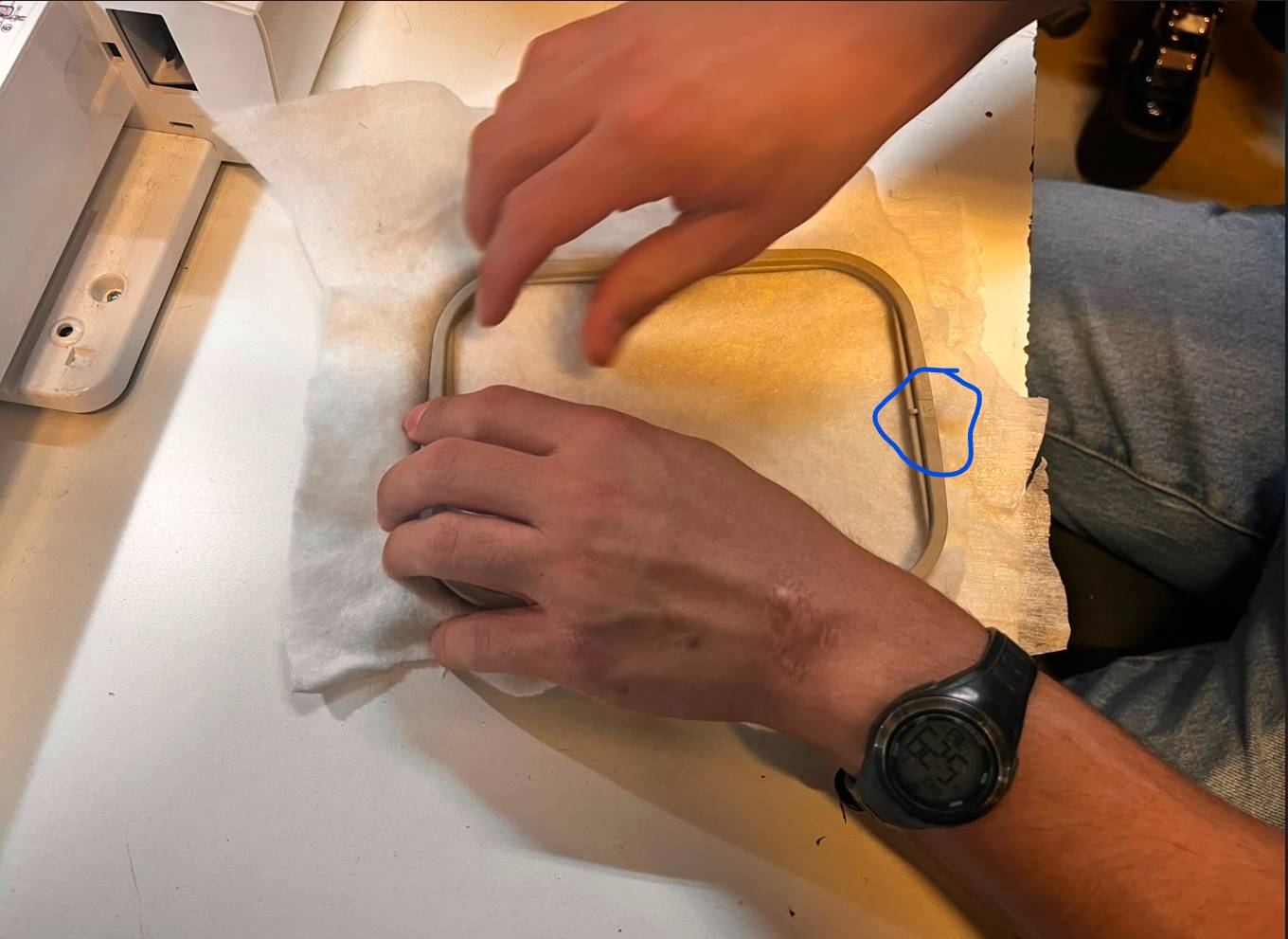
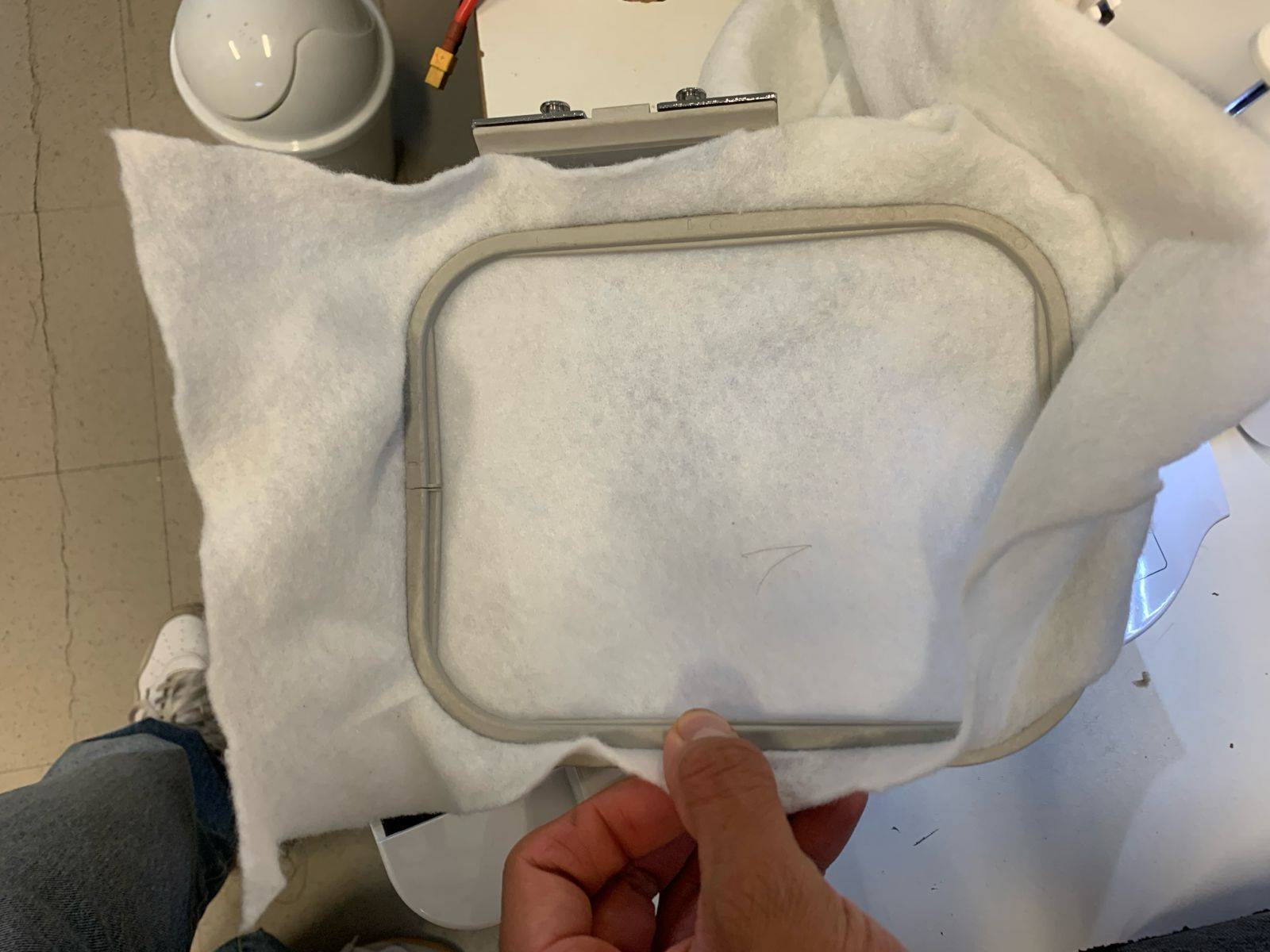
Fabric Tension Calibration
Pull and stretch the fabric stock as flatly and uniformly as possible inside the hoop to prevent gathering, bunching, or deformation during active stitching blocks.
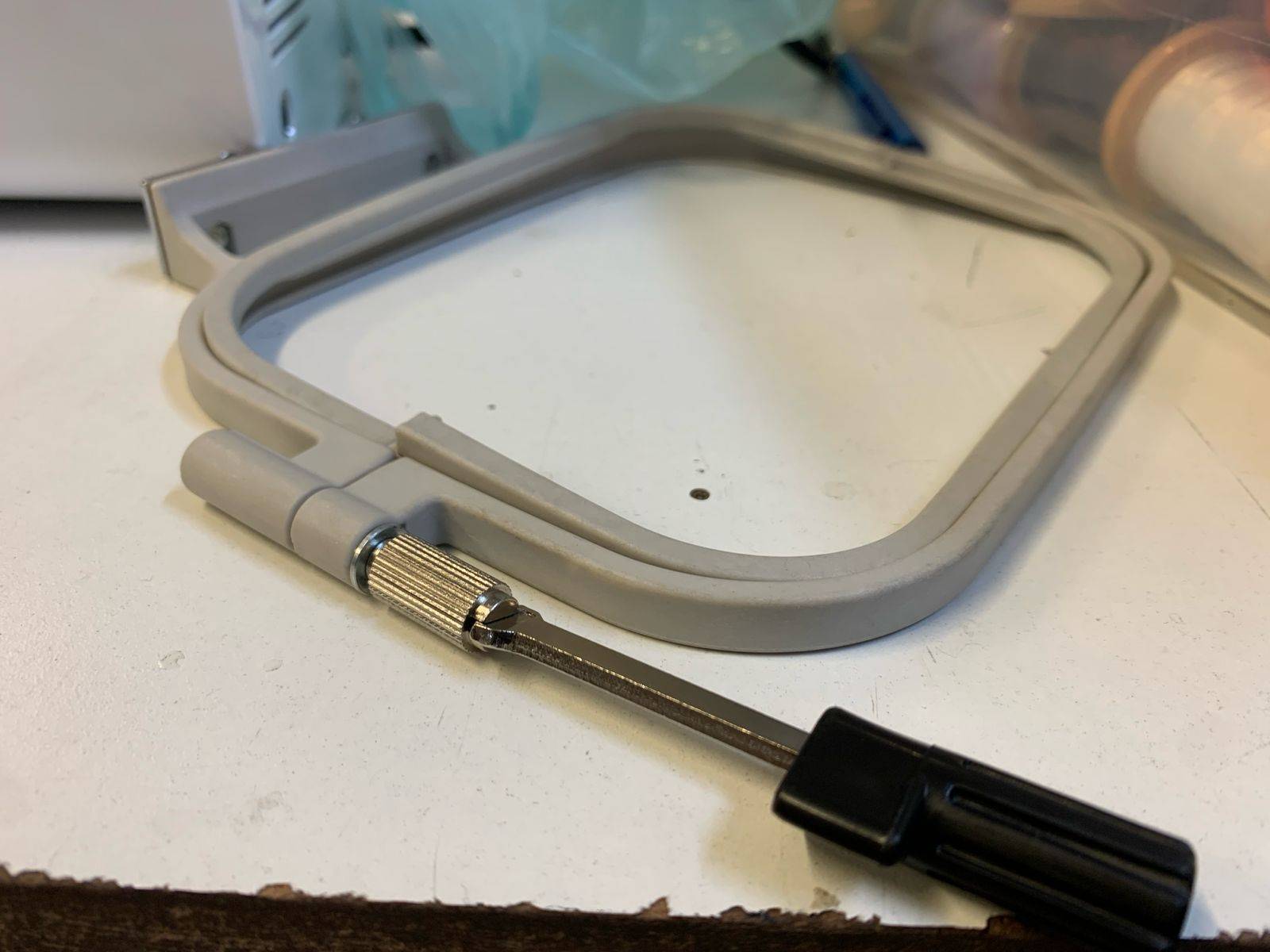
Mechanical Hoop Tightening
The hardware workstation includes a dedicated adjustment tool to secure the frame's thumb screw nut, allowing you to maximize tension when necessary.
Mounting Hoop to Workbed
Once the material tension is properly calibrated, snap the loaded frame hoop assembly back into the physical receiving locking arm of the machine's flatbed unit.
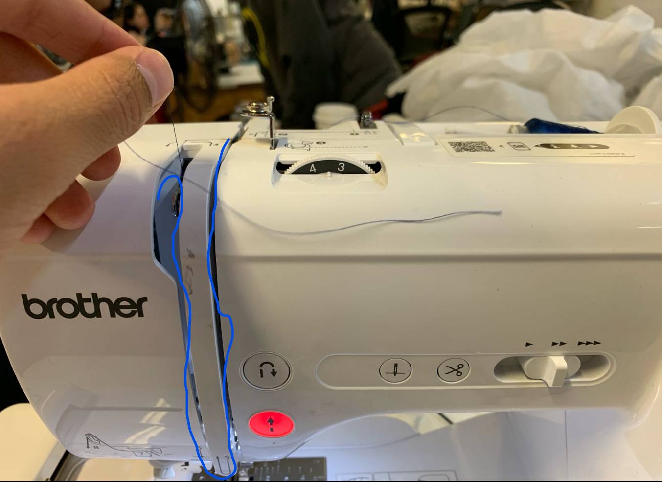
Upper Threading: First Hook
Mount your thread spool on the primary holder peg. Although the machine features quick reference layout prints, you must first feed the raw thread pathway directly through the upper metal guide hook.In my case I used Nylon thread.
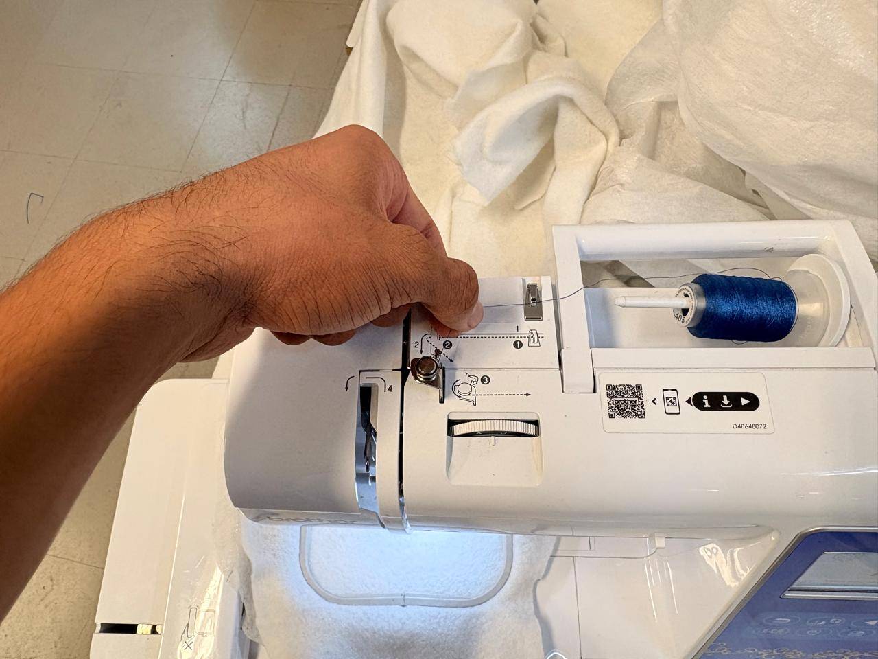
Descending Thread Guide
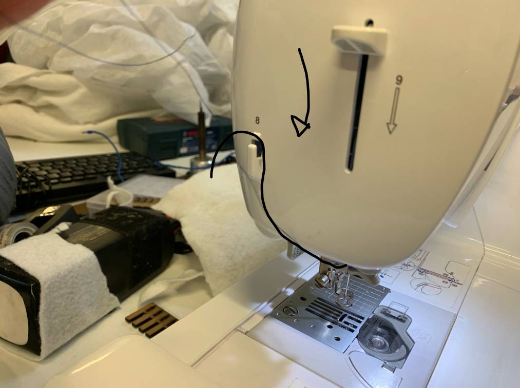
Pull the thread line downward through the main vertical tension slot compartment channel as indicated by the arrows embossed on the plastic housing.
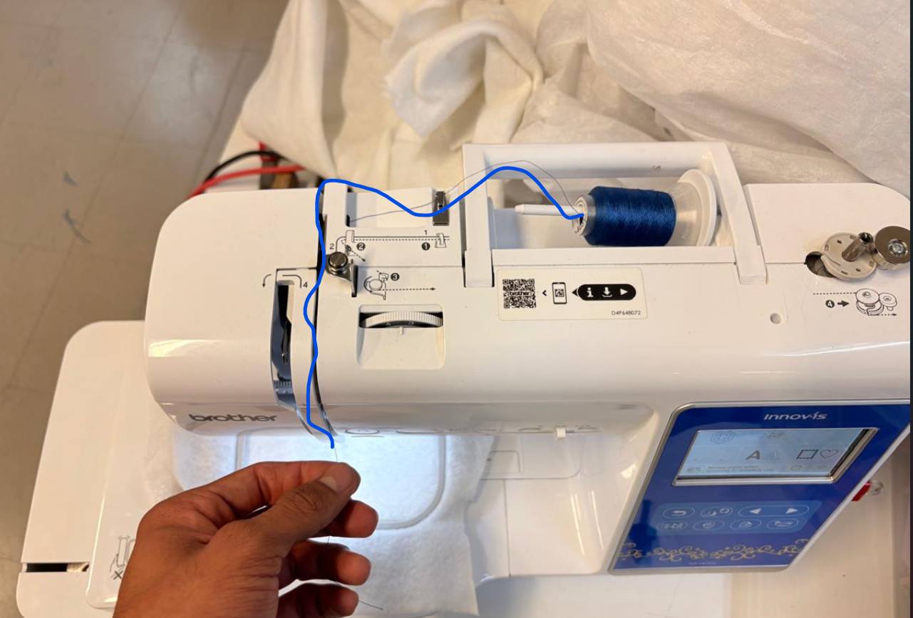
U-Turn Execution
Ensure that the thread wraps completely around the bottom base arc contour of the channel housing before starting the upward return pathway link.
Ascending Thread Pathway
Route the thread line back upward along the right interior side of the structural guide channel gap toward the top mechanical take-up lever mechanism.
Final Needle Descent
Hook the thread over the take-up lever eyelet and bring the line straight back down through the left vertical slot toward the lower needle assembly block area.
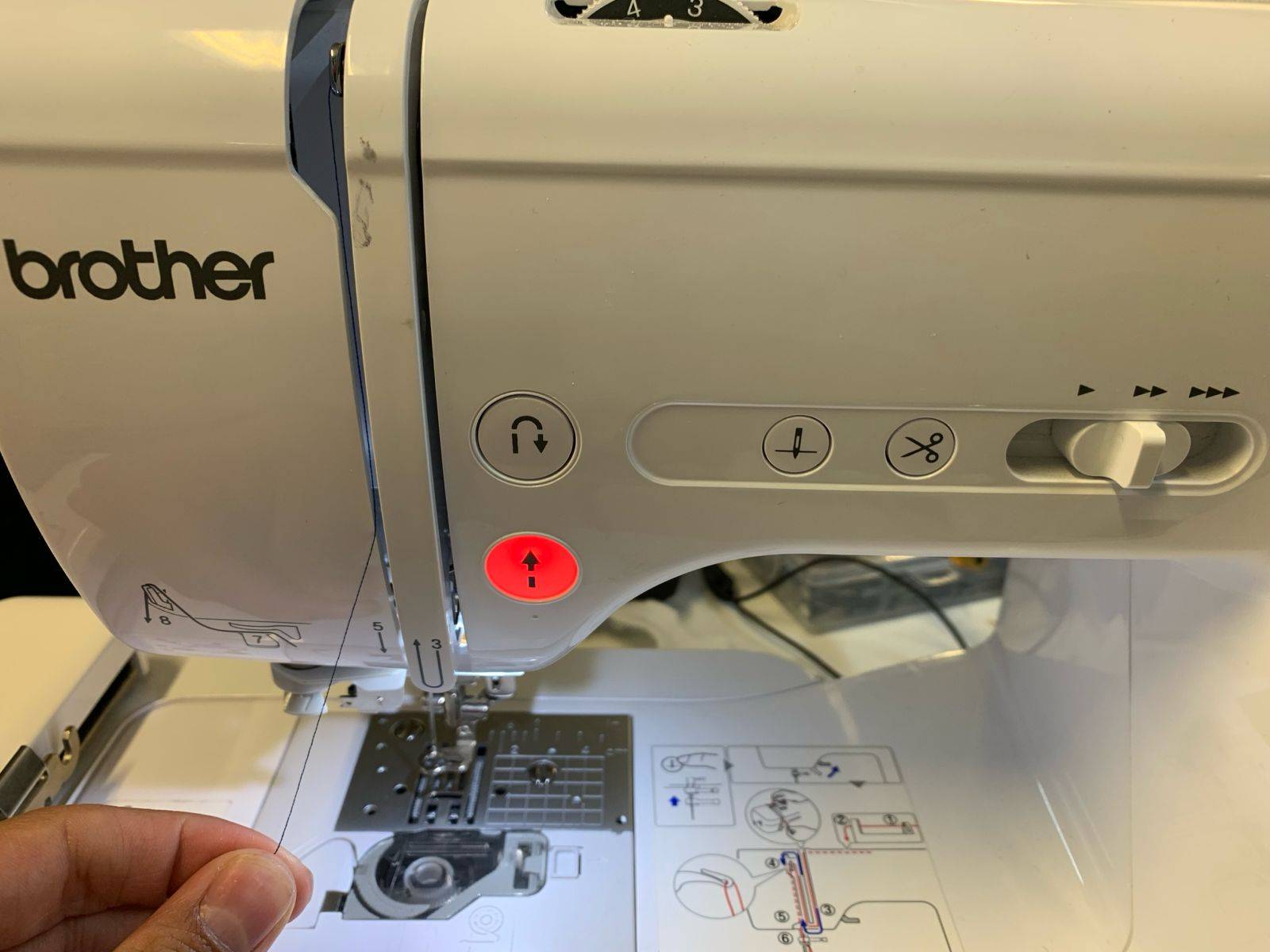
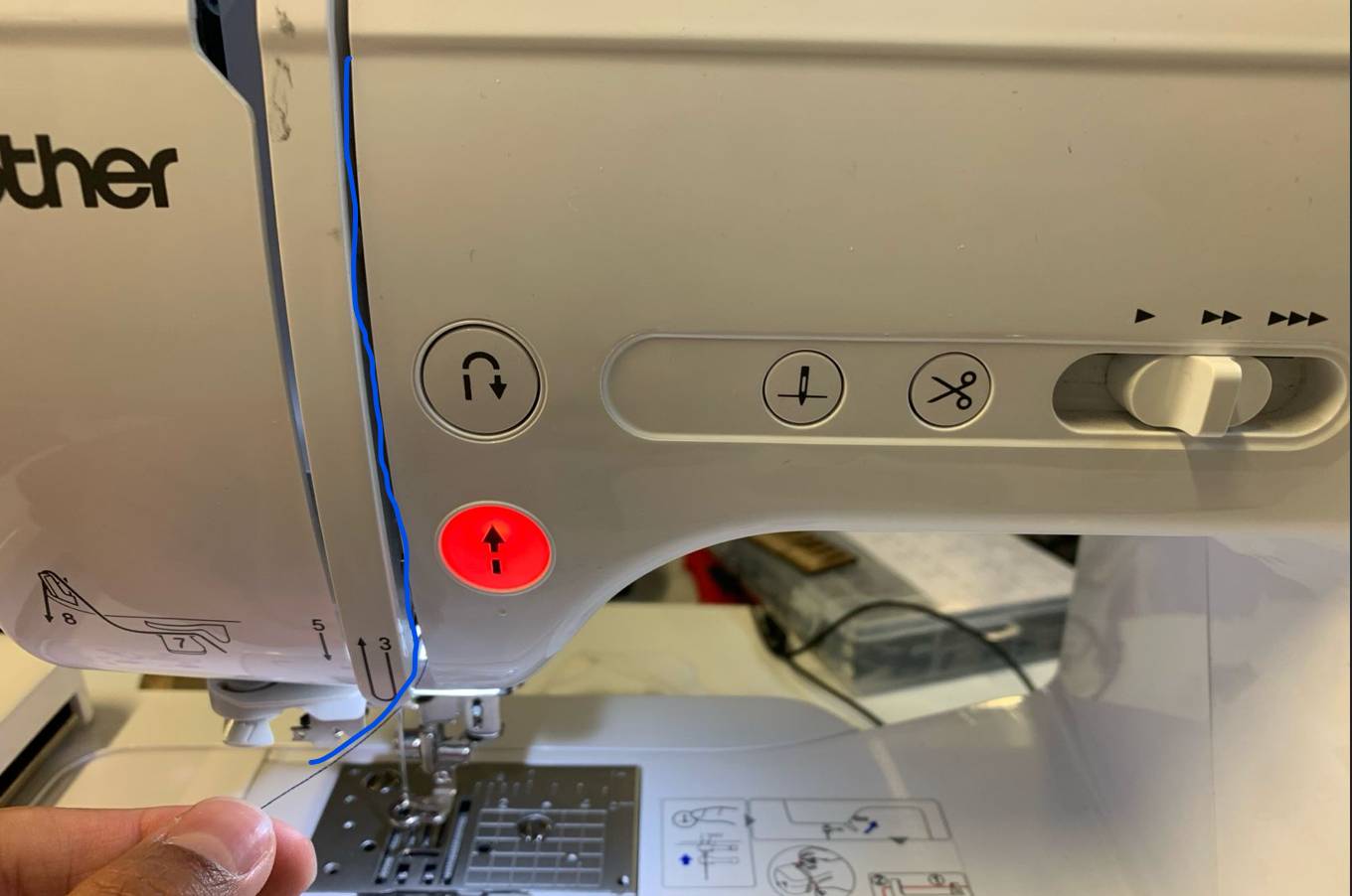
Needle Bar Guide Engagement
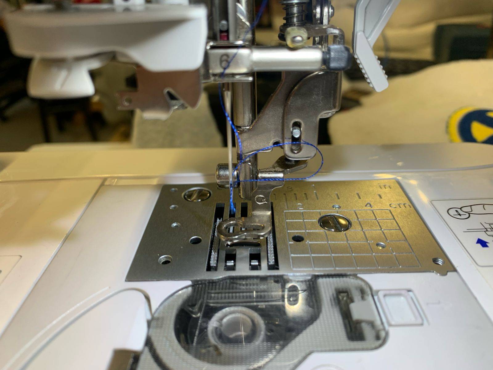
Once at the lower block assembly, lock the thread string securely inside the localized wire clip guide directly positioned over the top of the embroidery needle pin.
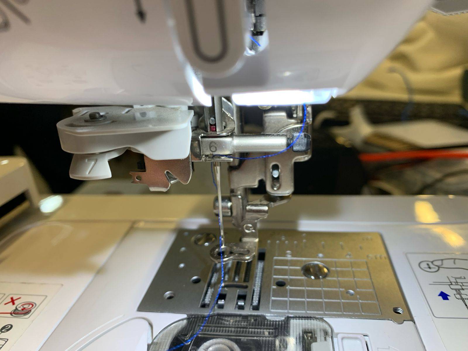
Semi-Automatic Thread Routing
Hook the thread line through the designated plastic slot marker and loop it around the structural track components labeled as number 7 inside the housing diagram.
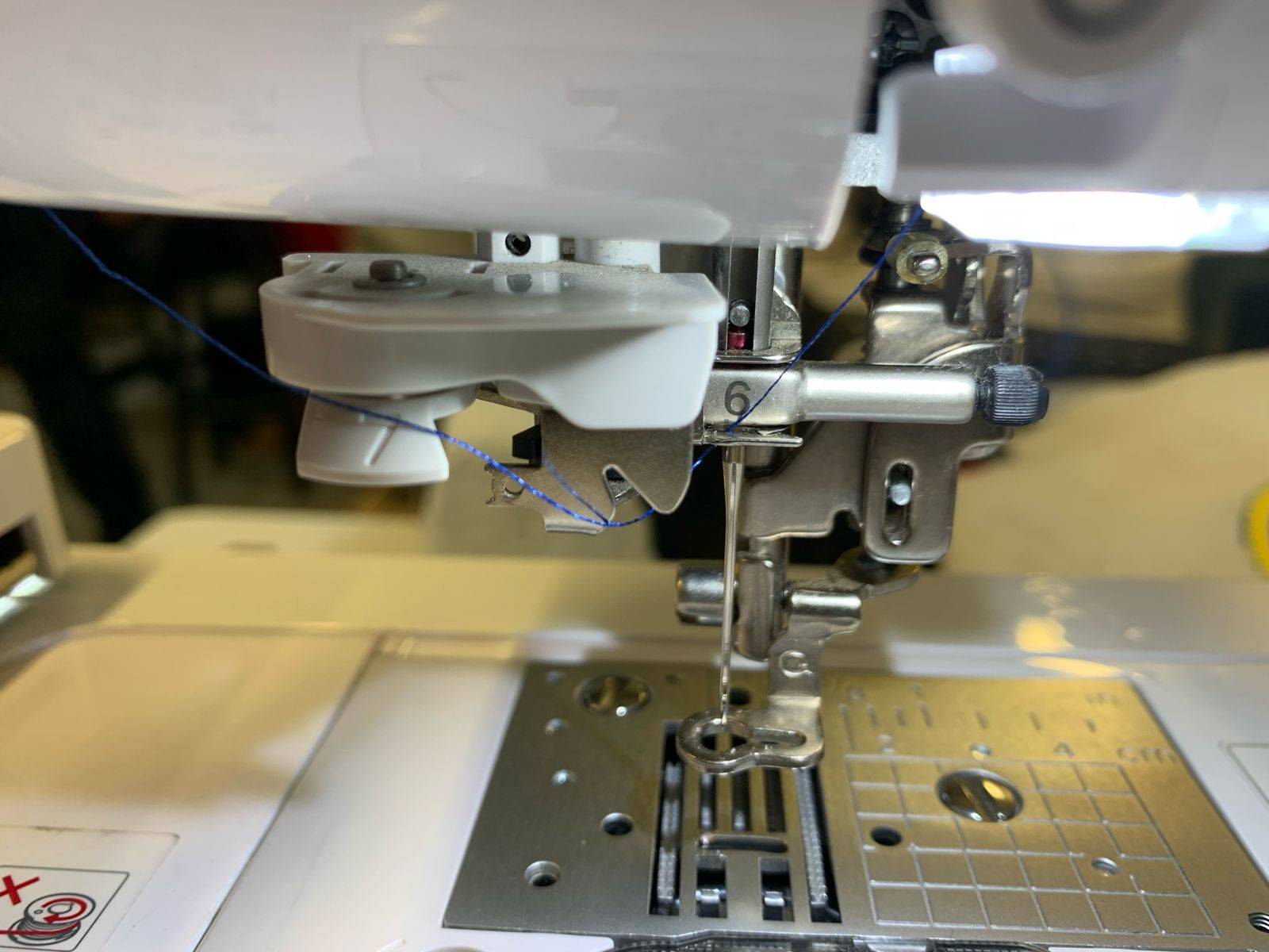
Automatic Needle Threader Mechanism
Catch the thread across target notch point 8 while manually pressing down on the automatic needle threader lever marked as 9. Swapping the sequence can also help ease execution.
Pulling Thread Loop
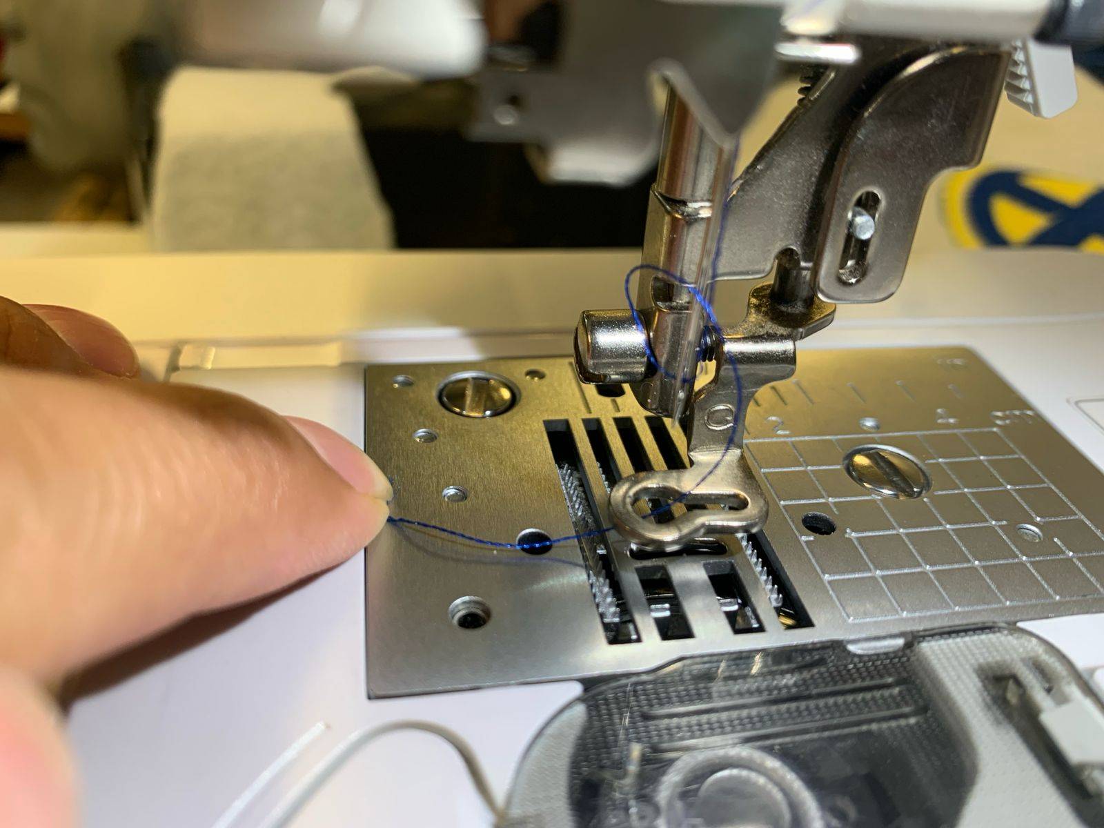
Releasing the manual mechanism slider lever pushes a tiny hook through the needle eye to catch the string. Pull the resulting thread loop entirely through from the rear side.
Clearing the Presser Foot
Pass the loose excess tail of your upper thread line underneath the central slot gap of the presser foot towards the back frame, as shown in the workspace photograph.
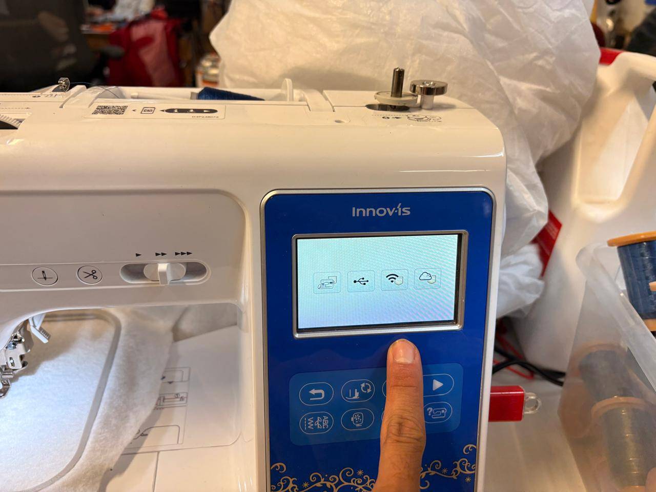
UI File Initialization
Turn on the LCD control panel. On the default software home navigation menu screen dashboard, press the dedicated USB folder interface icon.
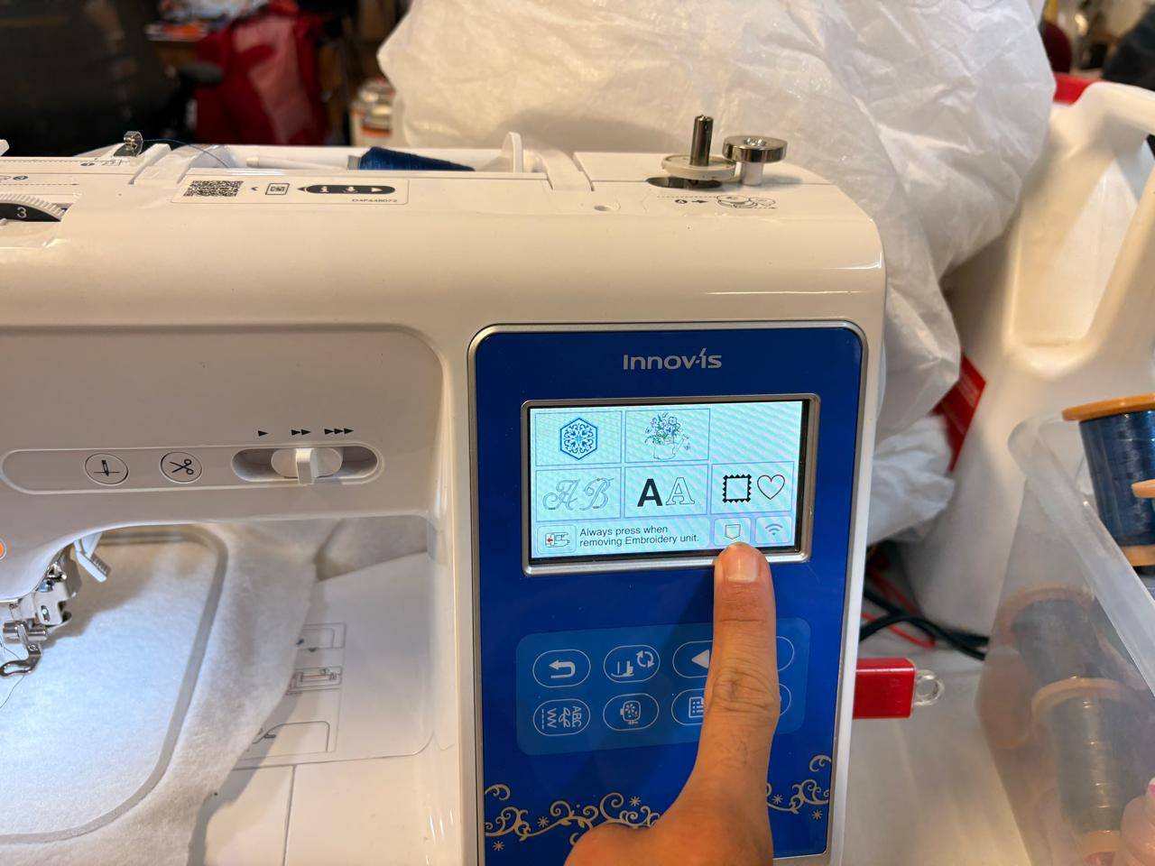
Accessing File Directory
Tap the second configuration folder button option from the left to access the root sub-directory contents of your loaded hardware drive unit.
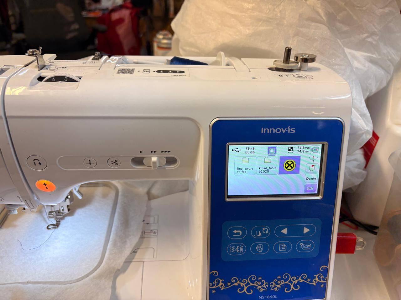
Loading Selected Design
Locate and highlight your specific custom .PES model toolpath item layout profile on the LCD matrix window, then press the 'Set' action button.
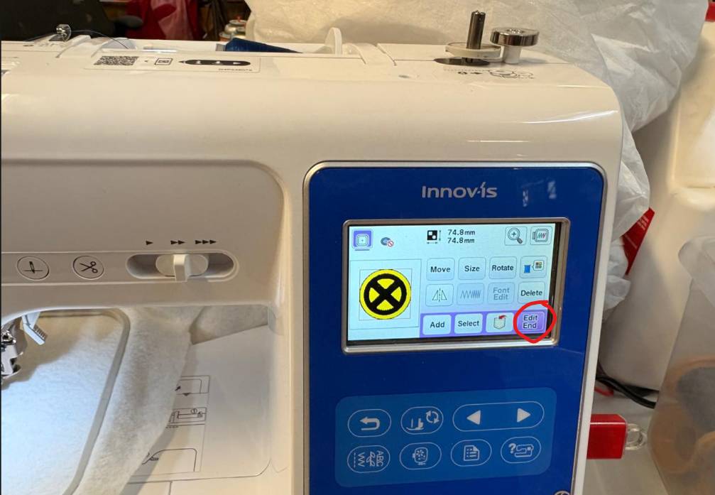
Ending Edit Mode
Verify coordinates on the positioning coordinate matrix, finalize scaling parameters, and tap the 'Edit/End' confirmation action key.
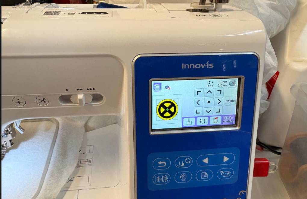
Embroidery Screen Execution
With compilation complete, choose and click the primary 'Embroidery' operations processing button layout to load the active run environment.
Presser Foot Engagement
Manually pull down the physical rear plastic tension lever mechanism to lower the machine's presser foot completely onto the stretched material surface layer.
CNC Run Activation
Press the physical glowing hardware execution button indicator on the front panel and monitor the automated toolpath system as it accurately embroiders your artwork matrix.
[ LIVE CNC MANUFACTURING: PROCESS CAPTURES ]
► LIVE CAPTURE: Real-time toolpath execution showing thread tension, pattern filling, and automatic color block transitions for the X-Men patch design.
[ PRODUCTION COMPLETE: X-MEN EMBROIDERY SHOWCASE ]
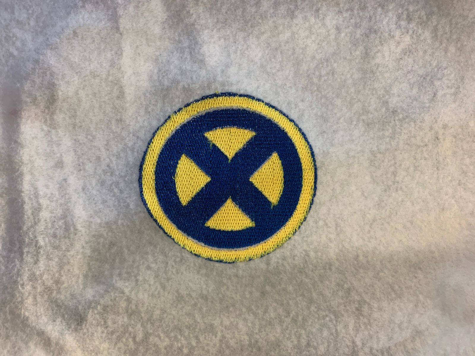
| ■ hardware_station: | Brother NS1850L CNC Workstation |
| ■ artwork_theme: | X-Men Circular Insignia Logo |
| ■ layer_optimization: | Boolean Difference Overlap Pruning (Passed) |
| ■ thread_sequencing: | Color-Grouped Blocks (Zero Needle Breaks) |
X-Men Embroidery Source Files
Download the verified .PES machine toolpath and optimized .SVG vector assets.