What is System Integration?
System Integration is the process of linking together different computing systems and software applications physically or functionally, to act as a coordinated whole. For this week, the challenge was embedding electronics, communication protocols, firmware, and mechanical packaging into a single standalone, ergonomic consumer product.
[ TARGET_GOAL: REMOTE_INTEGRATION ]
STATUS: COMPILED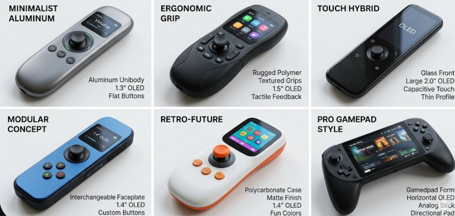
Project Vision: Designing a custom ergonomic handheld remote controller to pilot an electric skateboard. The system architecture utilizes low-latency ESP-NOW wireless protocol linking a transmitting XIAO ESP32-C6 (handheld) to a receiving node connected to a VESC/ESC to actuate a 5060 brushless motor (140 KV). The integration focuses on packing the PCB, lipo battery, charging circuit, and a hall-effect joystick safely within a compact, robust resin shell.
SELECT INTEGRATION SYSTEM PHASE.
[ PHASE 01: BRAINS AND PROTOCOL ]
Component Selection
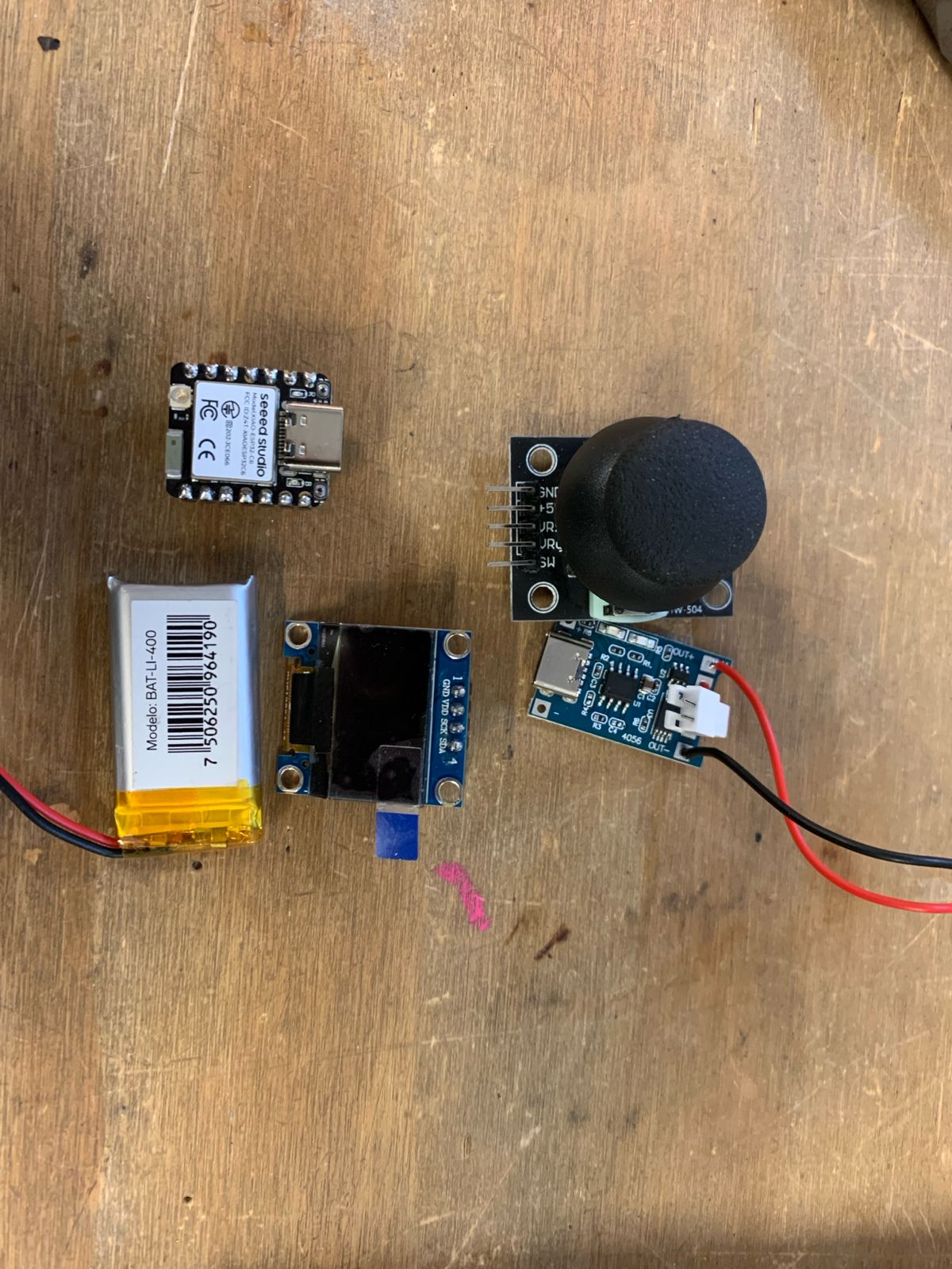
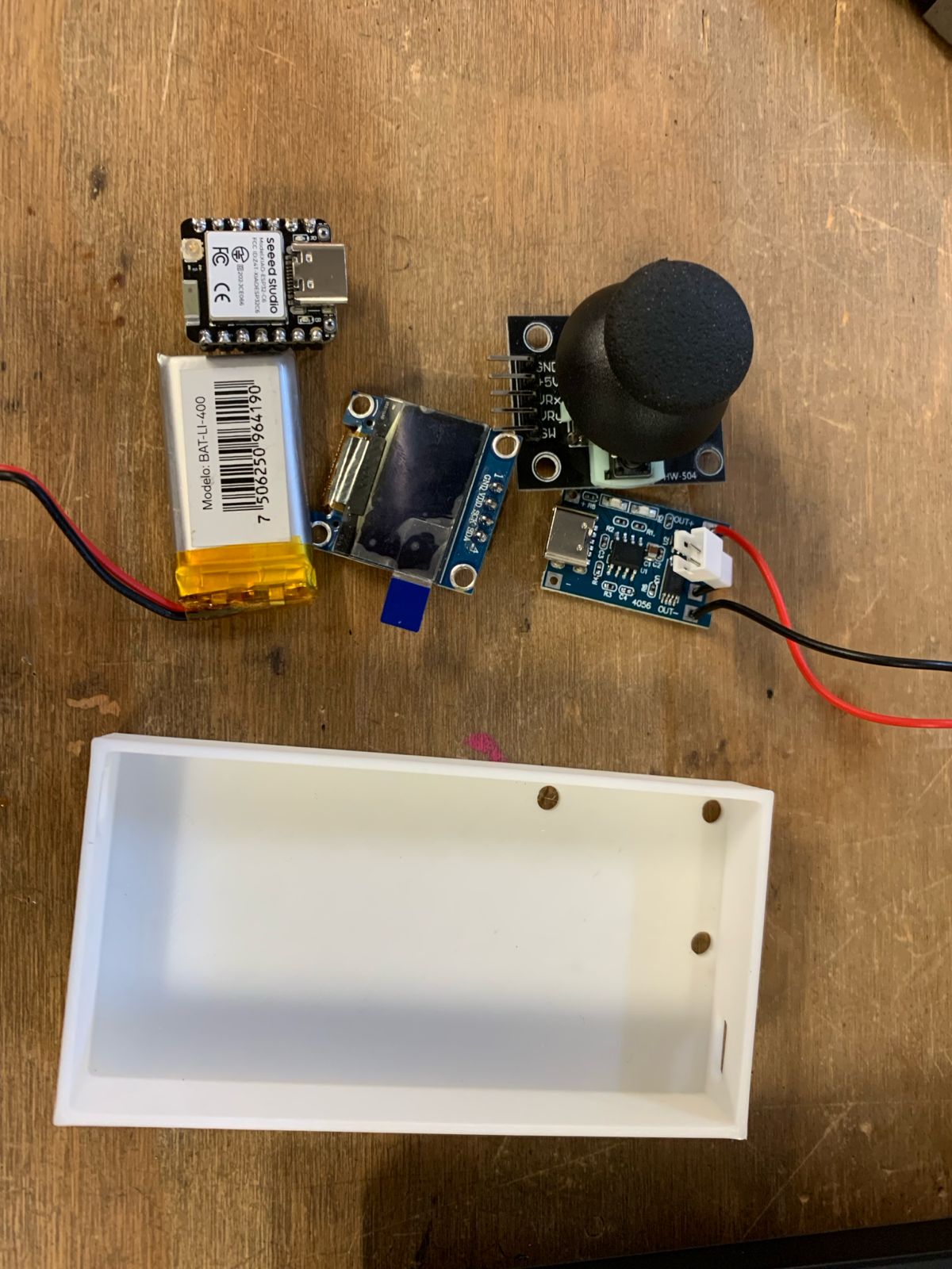
For this custom handheld remote controller, I selected a specific set of hardware components: an analog joystick, a 3.7V 400mAh LiPo battery, a XIAO ESP32-C6 microcontroller, a 128x64 I2C OLED display, and a dedicated LiPo battery charging module.
Ergonomic Architecture Challenge
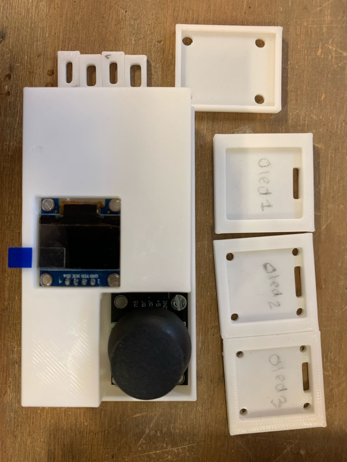
The primary challenge was integration: packing every component into a single device that remains comfortable for single-handed use. To validate spatial layout constraints, I printed a testing enclosure at the maximum scale allowed by human ergonomics.
Compact PCB Design
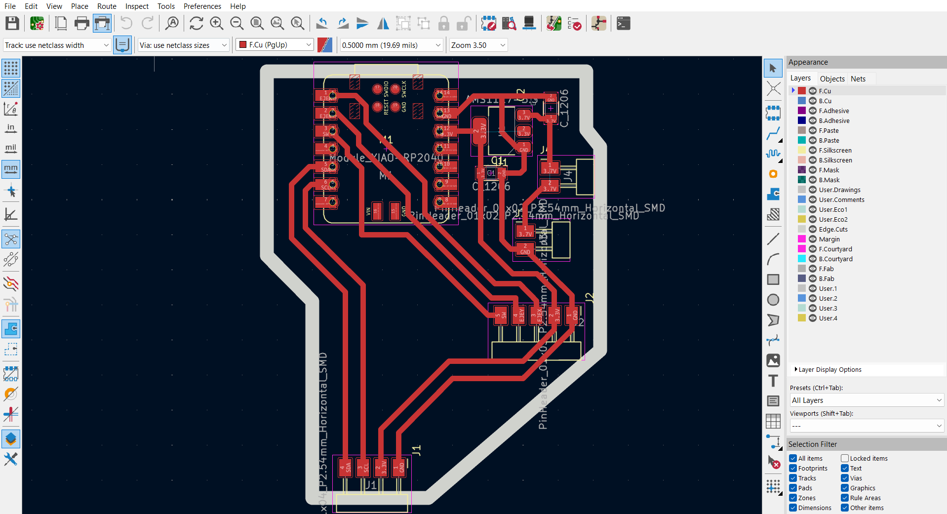
Once the physical volume and dimensional boundaries were set, the next step was designing a custom, ultra-compact PCB using CAD software. The layout was optimized to route and house all elements into a minimal footprint.
Hardware Optimization & Modular Assembly
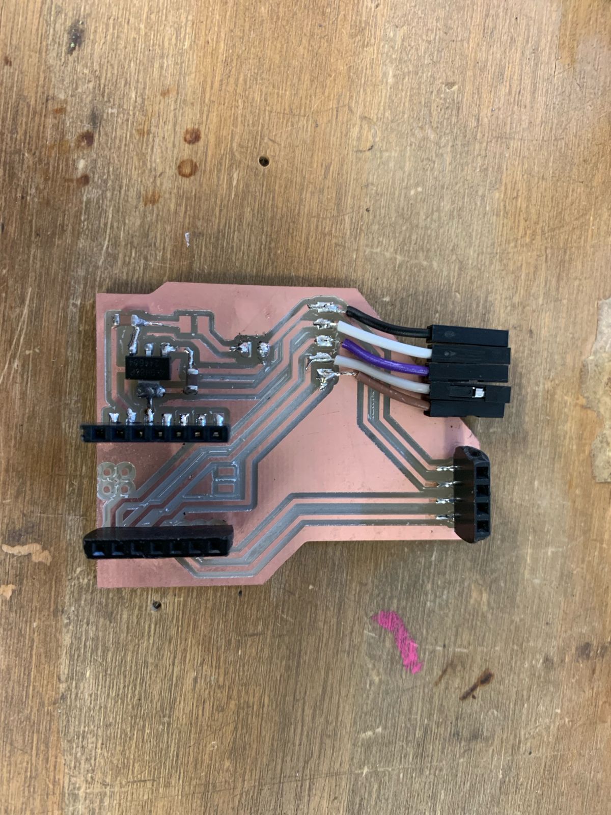
The final board layout includes a 3.3V voltage regulator and 10µF filtering decoupling capacitors to prevent dangerous voltage spikes. For high modularity, I populated female headers for both the XIAO board and the OLED screen to allow easy removal, while adding dedicated female jumper connections for the joystick module wiring.
Standalone Electronic Validation
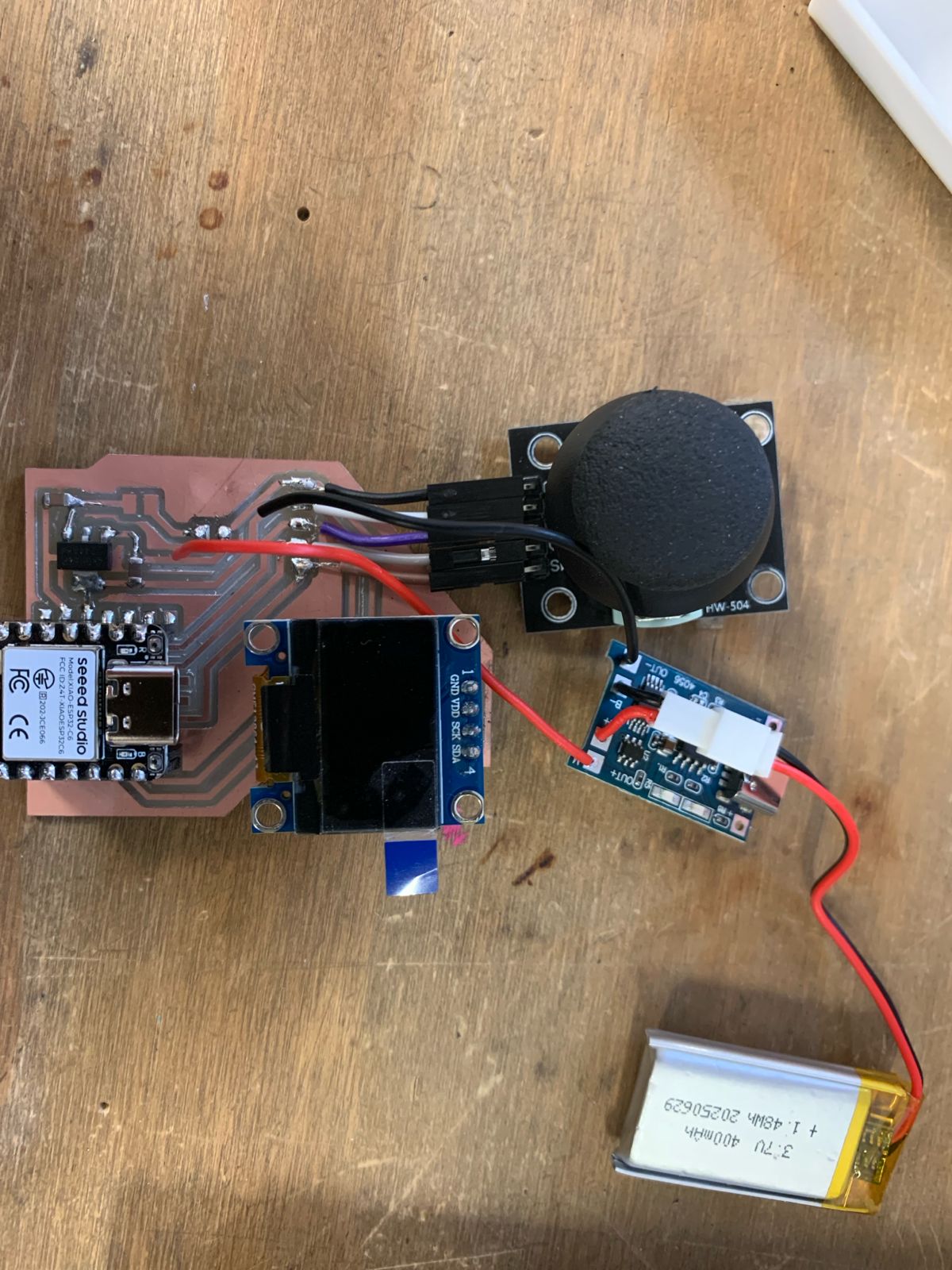
This is how the standalone custom system looks outside of its structural housing. The board successfully integrates power management, status visualization, user inputs, and low-latency ESP-NOW RF transmissions into a single sub-assembly.
[ PHASE 02: MECHANICAL HOUSING ]
USB-C Interface Design
To begin developing a compact and practical enclosure, I started by designing the precise cutouts and clearance entries for the USB Type-C ports. This ensures easy structural access for both programming the XIAO microcontroller and plugging in the LiPo charging module.
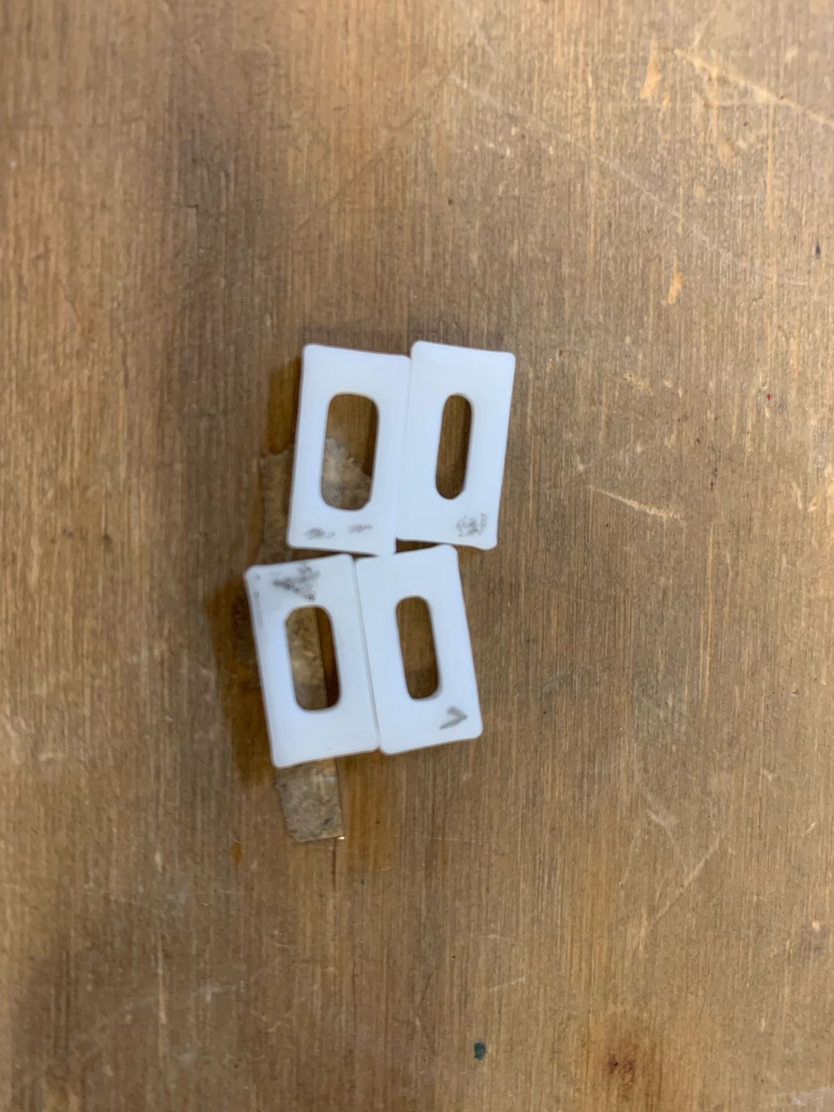
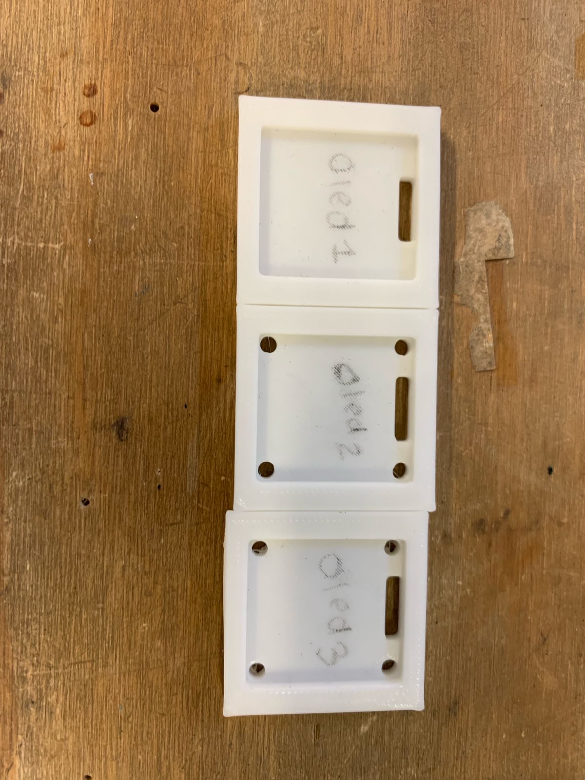
OLED Display Mounting
For the next phase of the housing, I modeled a dedicated structural support framework at the top of the enclosure to integrate and lock the 128x64 OLED display securely into position for optimal user visibility.
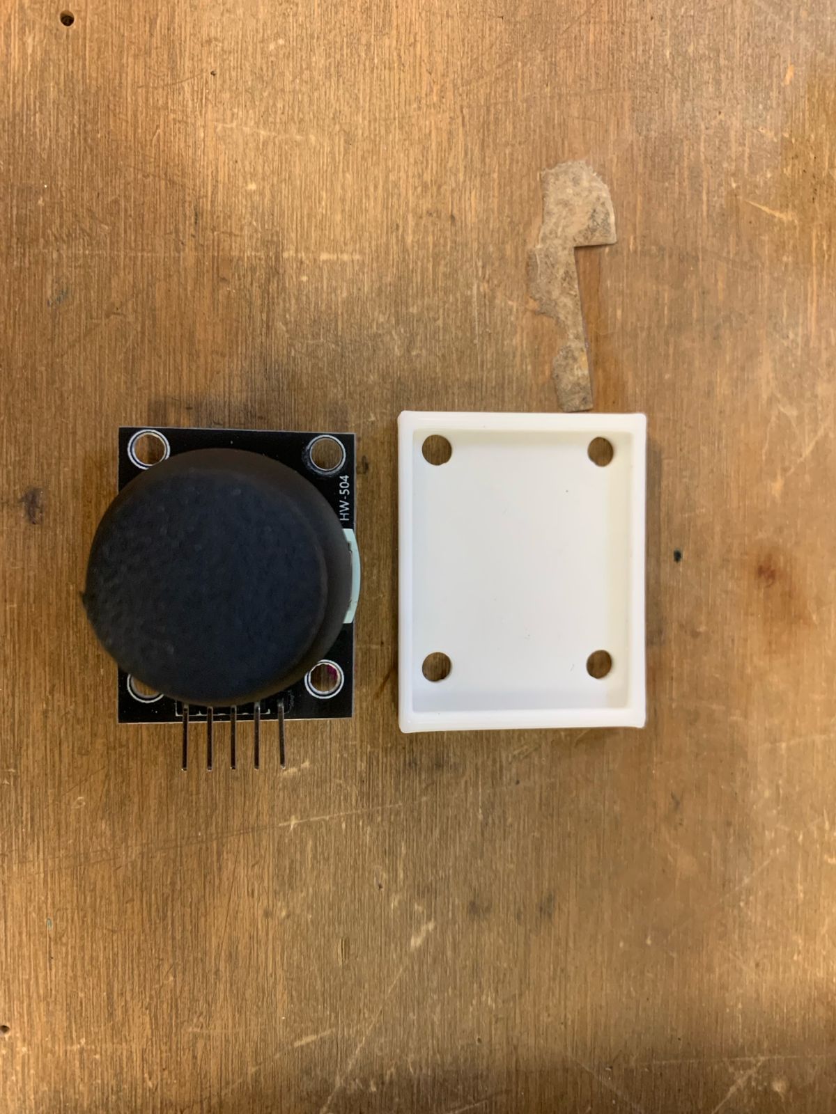
Joystick Fastener Integration
To guarantee operational stability during use, I engineered a specialized internal mounting base for the joystick module, embedding specific thread columns optimized for standard M3 mechanical screws.
Full Component Consolidation
Finally, I integrated each individual sub-component support structure into the global enclosure volume that I had originally designed. The resulting unified digital assembly is arranged exactly as shown in the model.
Design Iteration & Clearance Correction
In the first design prototype, I failed to account for the physical dynamic clearance required by the joystick's maximum travel range. I re-engineered the enclosure shell, applying dimensional modifications and adjustments to guarantee unobstructed mechanical movement for the throttle.
[ PHASE 03: FULL COHESION AND TEST ]
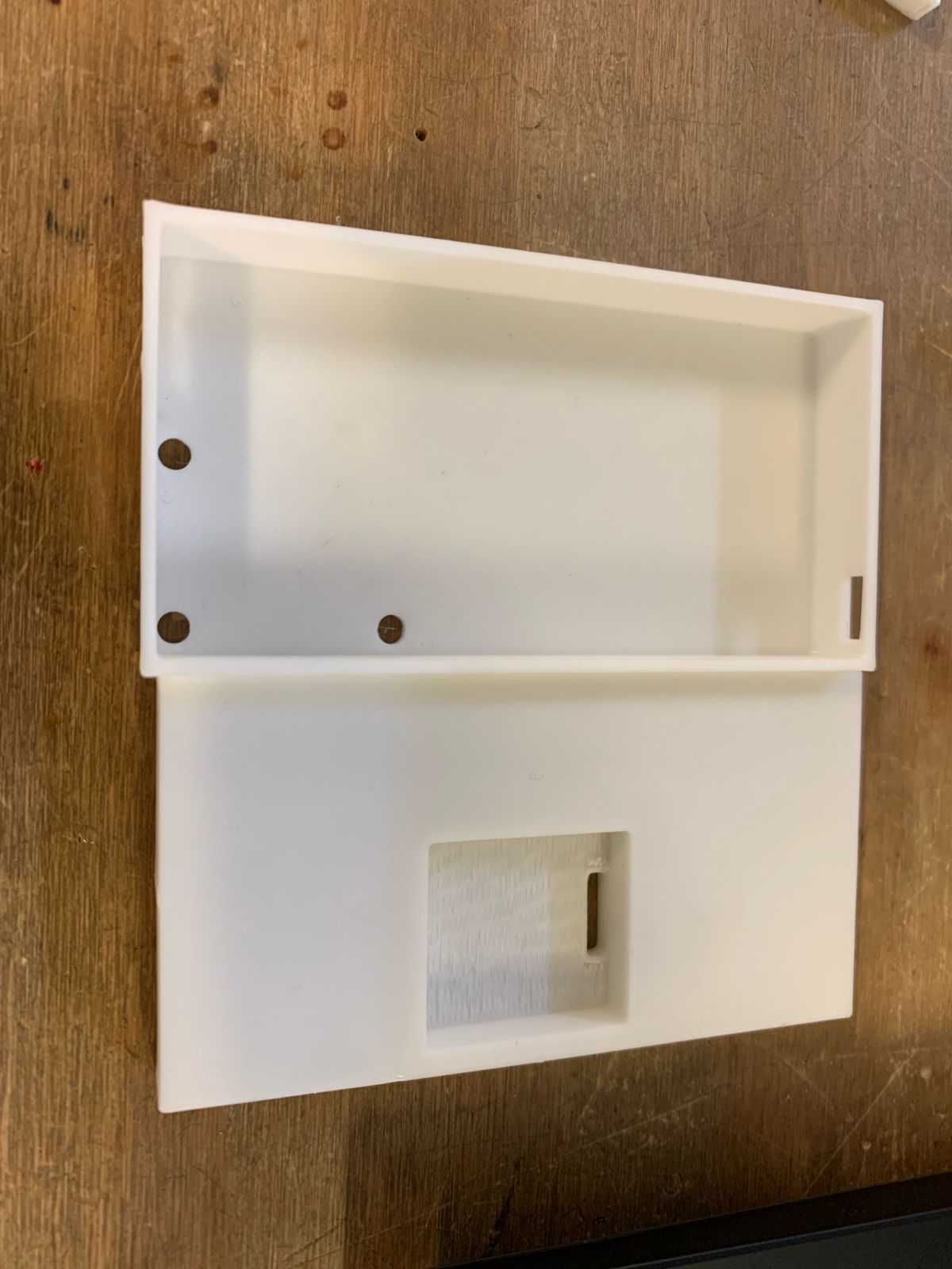
3D Resin Printing Execution
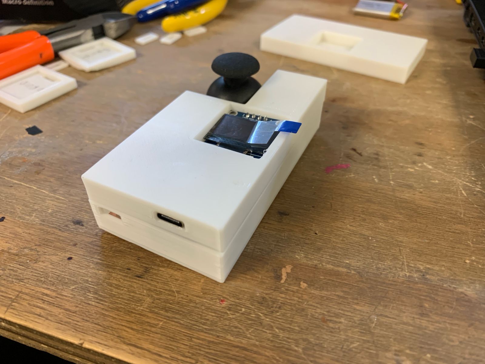
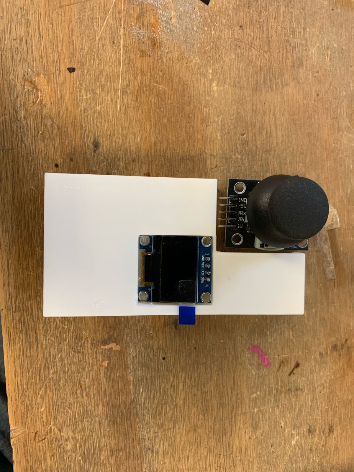
Step 1: Once I attached the PCB to the floor with double-sided tape, and the joystick with its screws, as well as the screen in its slot, the parts of the casing looked like this:
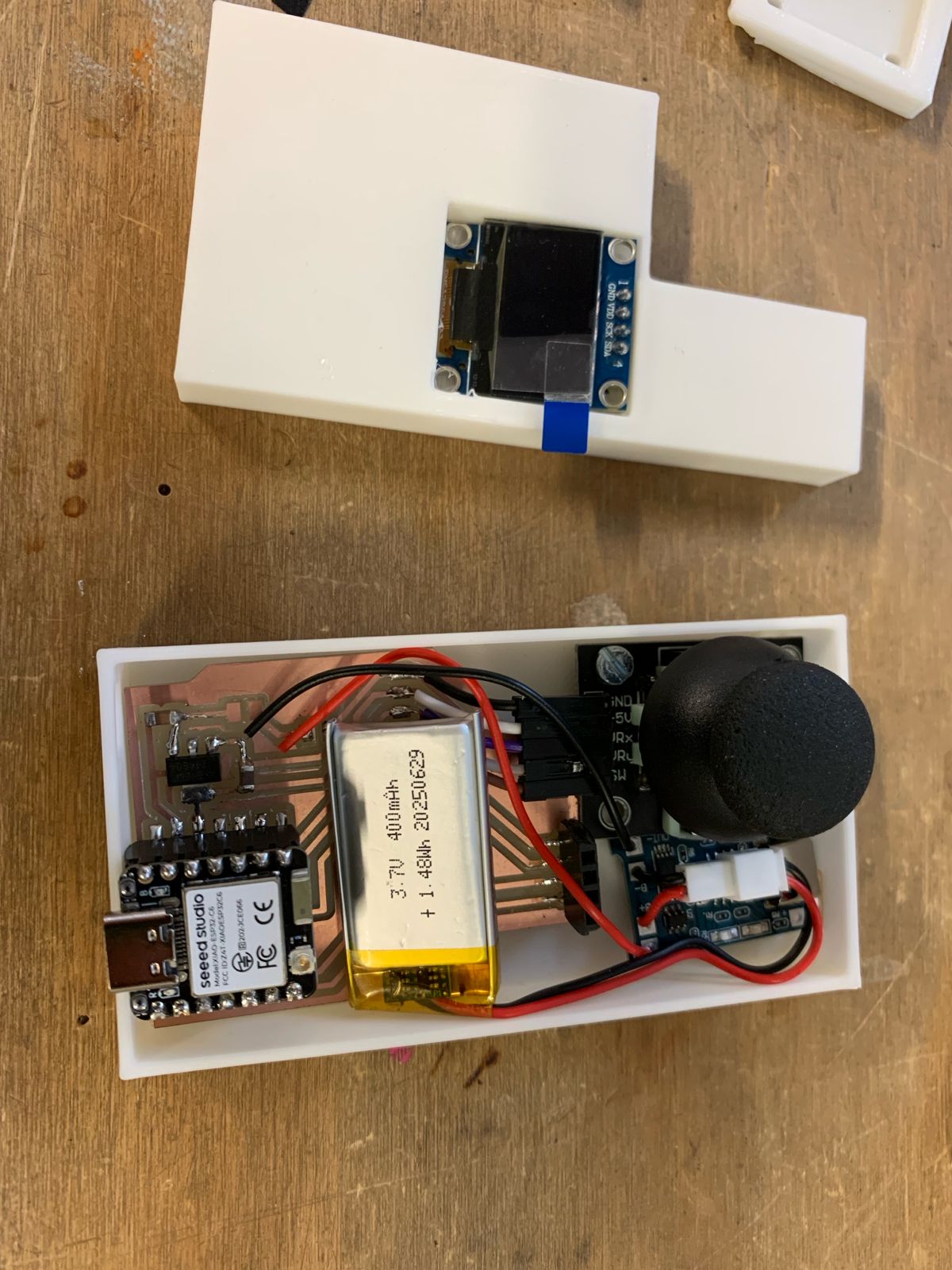
Internal Component Packing
Carefully positioned the modular PCB, slotted the I2re routprevent pinning during final closure.