[ BASIC INFO ]
> 3D PRINTING (ADDITIVE MANUFACTURING)
3D Printing is the process of creating physical objects by successively overlaying layers of material based on a digital model. In engineering, it enables Topological Optimization (creating lightweight yet ultra-strong parts) and Rapid Prototyping to validate mechanical designs in a matter of hours.
[Image of additive manufacturing process diagram]- • Tooling: Development of customized manufacturing aids and jigs.
- • On-Demand: Production of spare parts without the need for physical inventory.
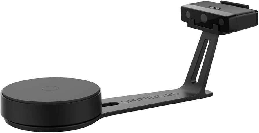
> 3D SCANNING (DIGITAL CAPTURE)
This technology analyzes a real-world object to collect data on its shape and geometry. The output is a Point Cloud that is subsequently processed into a digital mesh (STL). It is essential for Reverse Engineering and Metrology (quality control by comparing physical parts against the original CAD data).
- • Metrology: High-precision measurement with micrometric accuracy.
- • Ergonomics: Adapting industrial designs to fit human anatomy perfectly.
SELECT FABRICATION METHOD.
[ MISSION: DIGITAL CAPTURE ]
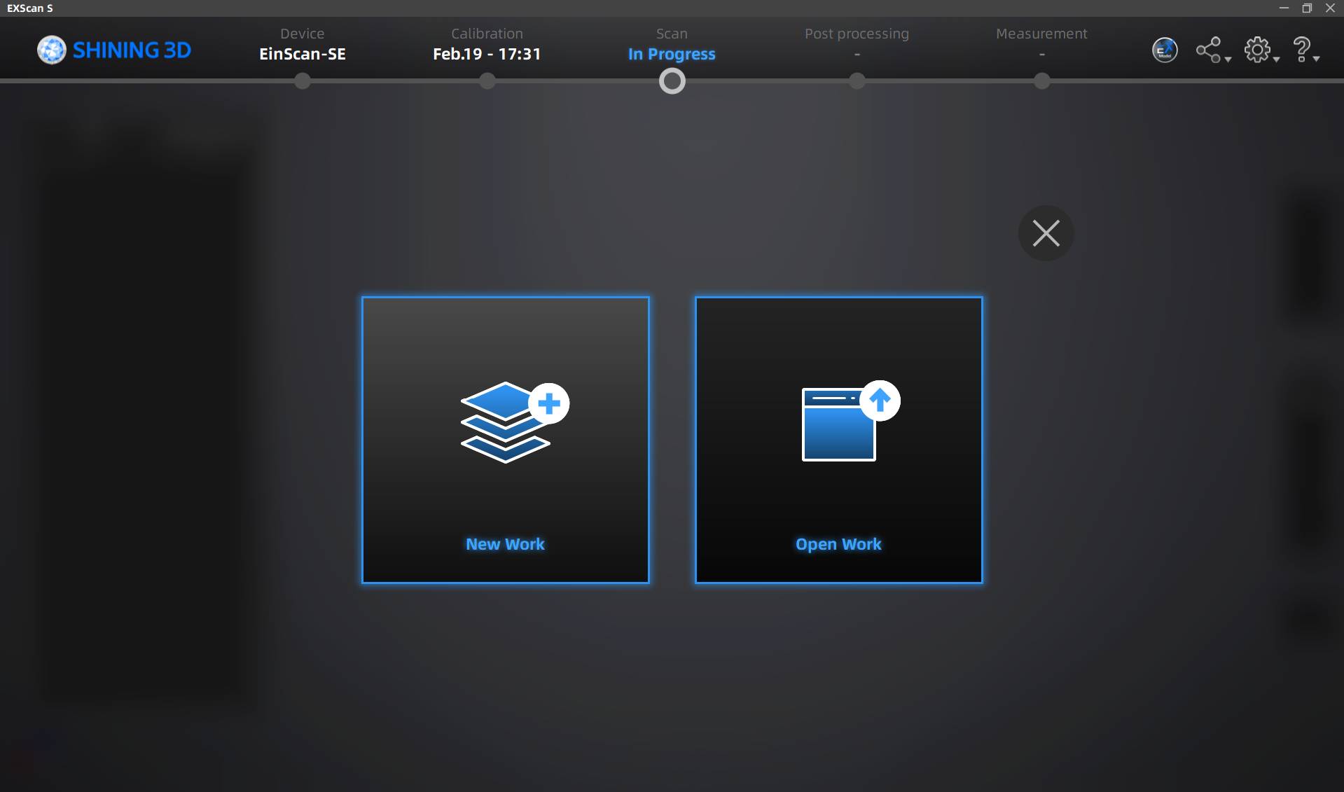
Initial Connection
First, turn on the scanner and connect it to the laptop. Once done, open and initialize the program. On the screen, click the option to create a new project to start.
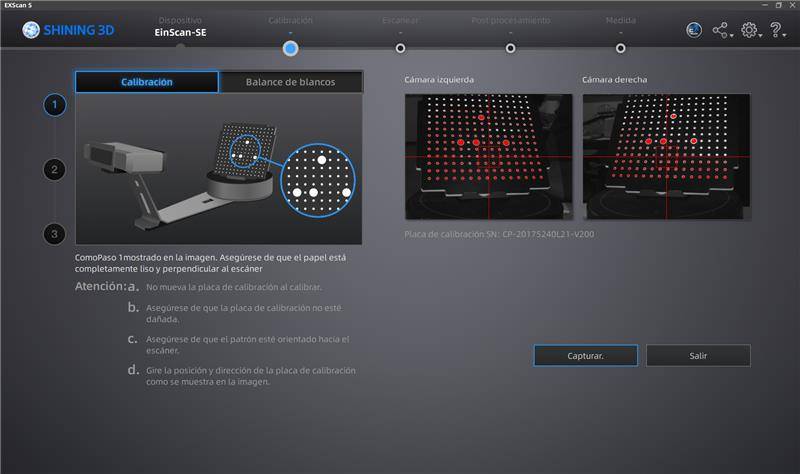
Pattern Board Calibration
To begin scanning, it is necessary to calibrate the scanner using the pattern board and stand included in the box. Instructions on how to place it will appear on the calibration screen; follow the steps to pass the 3 required calibration points.
Purpose of Calibration
3D scanner calibrations are mainly performed to ensure that captured data is a faithful and precise representation of reality. Without this process, the sensor may lose its sense of depth or scale, generating deformed models.
White Balance
After the board calibration, it will ask for a white balance calibration. Place a completely white sheet on top of the board and start. This is fundamental for chromatic fidelity; while standard calibration adjusts geometry, white balance adjusts the visual appearance.
Starting the Scan
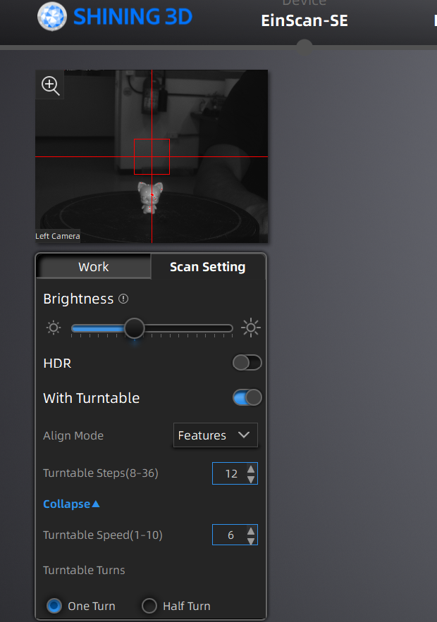
Once finished, you can proceed to the general operations screen. Place your piece in the desired position on the turntable and use the "Start Scan" button on the right side to begin scanning your chosen figure.
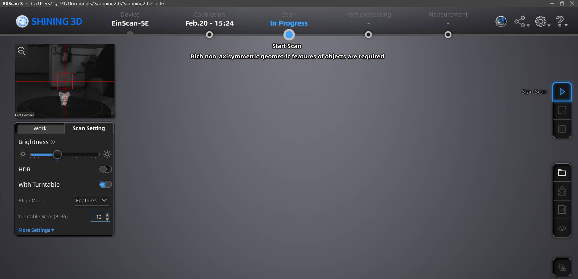
Operation Settings
On the left side, under the scanner camera, you will see an operation bar where you can adjust the scan light, the number of rotations, and the rotation speed. If you want the figure to build itself automatically from multiple scans, select the "Features" option in the "Align Mode" section.
Process Execution
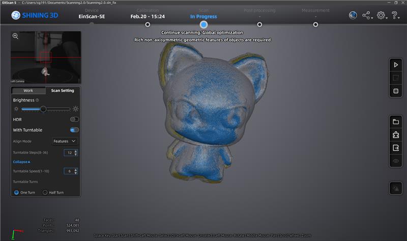
Once your scan begins, you should see something similar to what is shown in the video as the turntable and sensor sync.
Data Interpretation
After each scan, you will see the construction of your object. Yellow sections mean they are empty or require more scanning. As you use more positions and angles, the figure will turn grey in the parts that are completely defined.
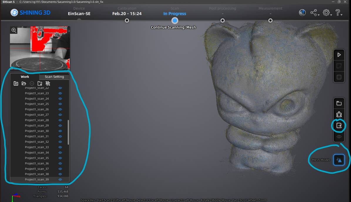
The Mesh Model
On the left, you can see the scans that make up the model. On the right, the top option exports the scan, and the bottom one is for the Mesh Model: the result of transforming the unorganized point cloud into a solid surface of polygons (triangles).
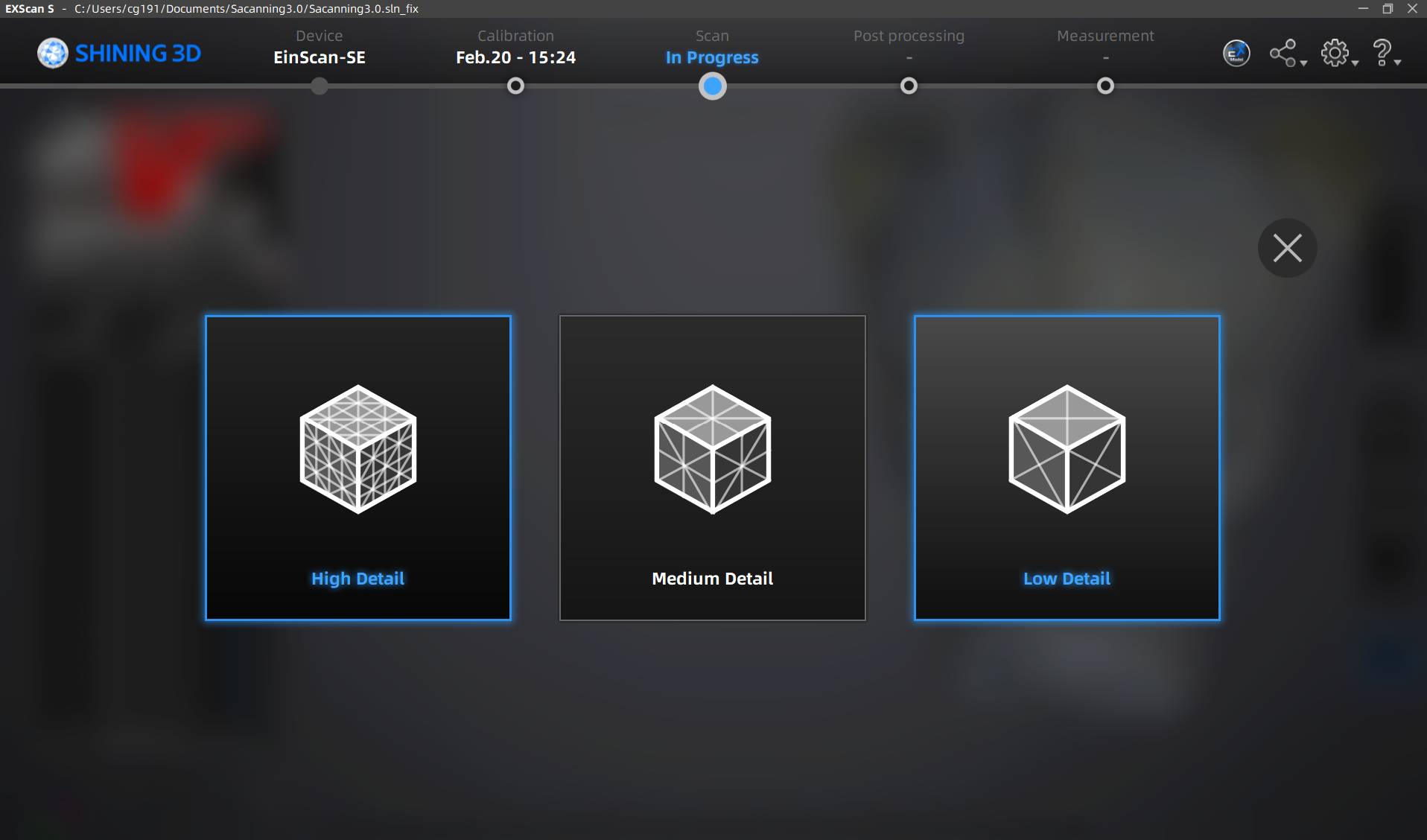
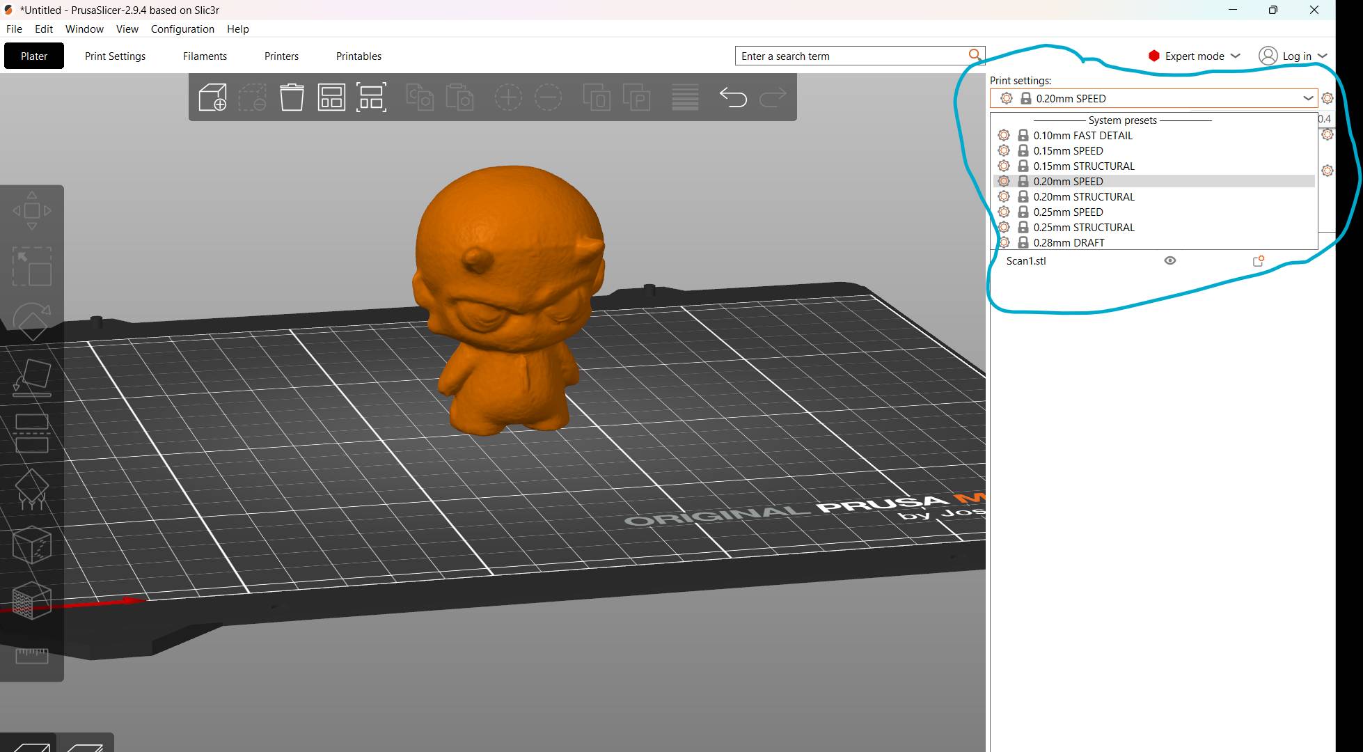
Quality Selection
If you select the mesh model option, you can choose the operation quality. Choose the option that your computer allows, as this operation can sometimes be very heavy for the hardware.
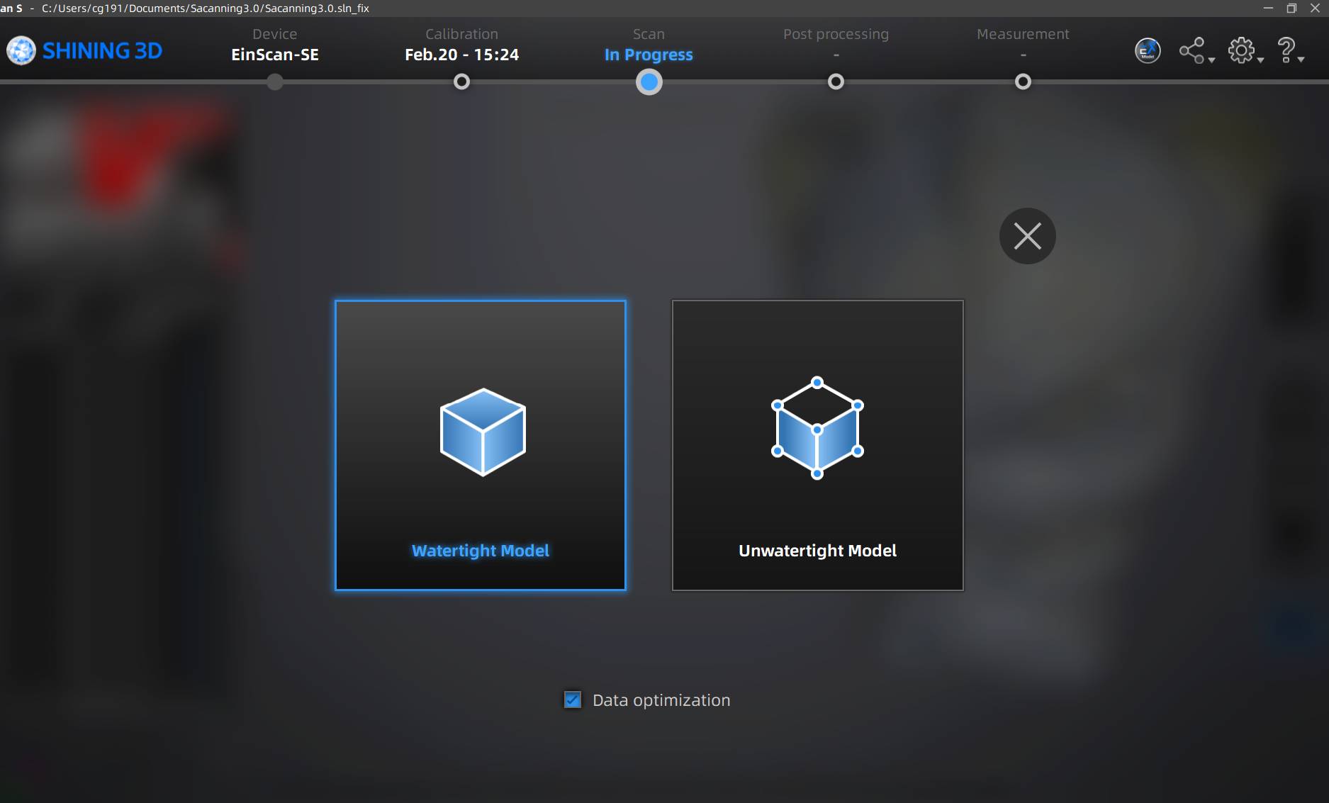
Watertight Export
When ready to export your model to STL for printing, you can choose between Watertight and Unwatertight models. In my case, I used the Watertight model to ensure a closed, 3D-printable solid without holes.
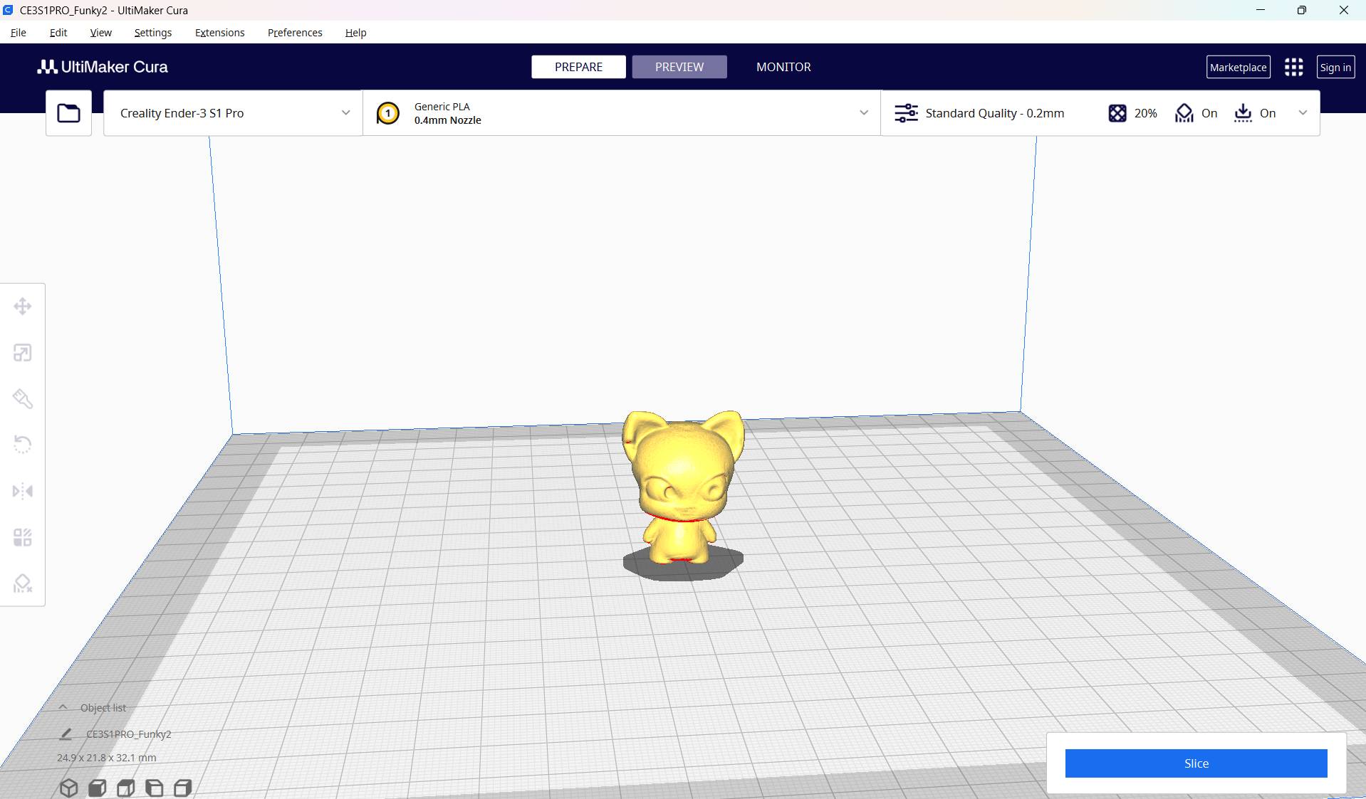
Final Preparation
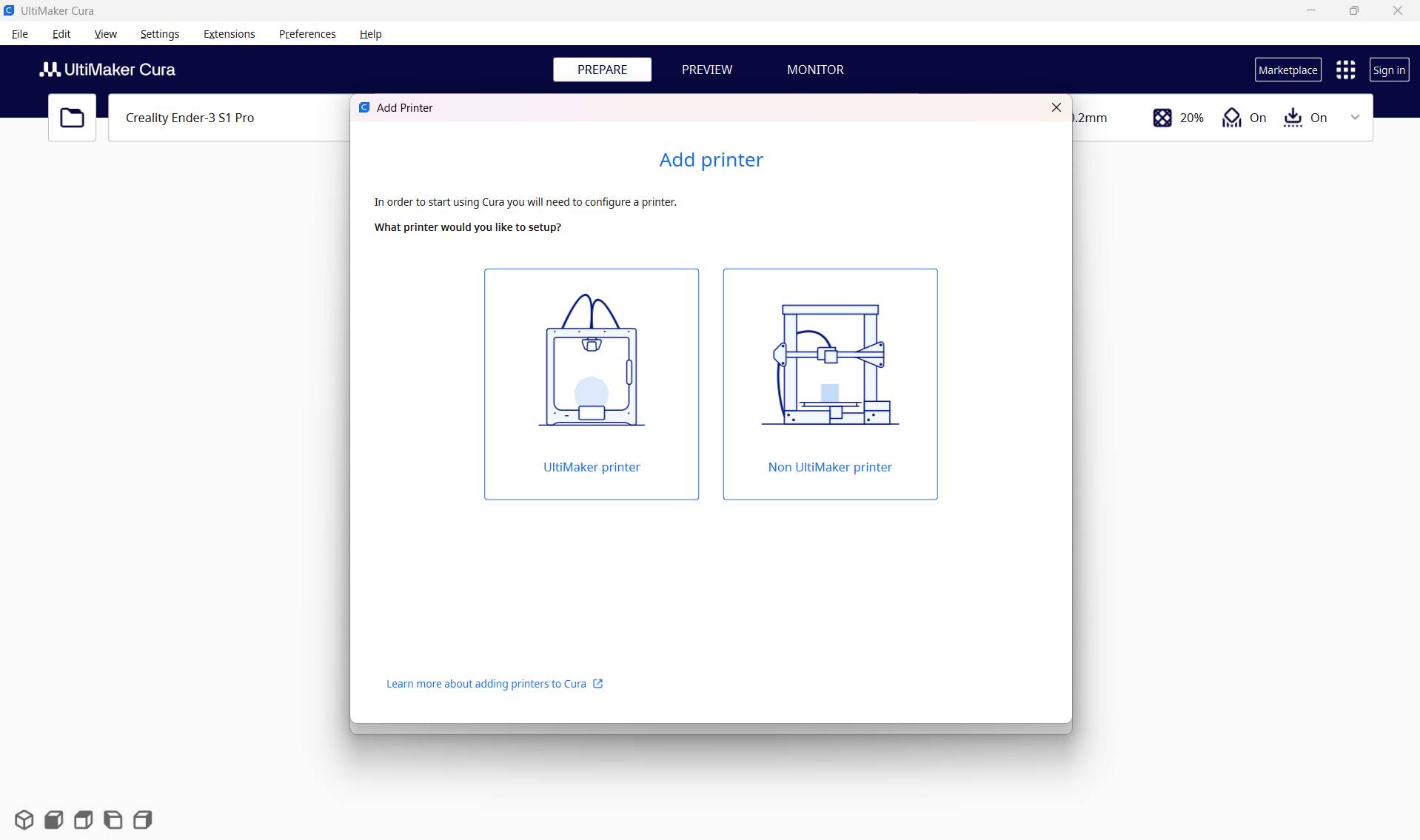
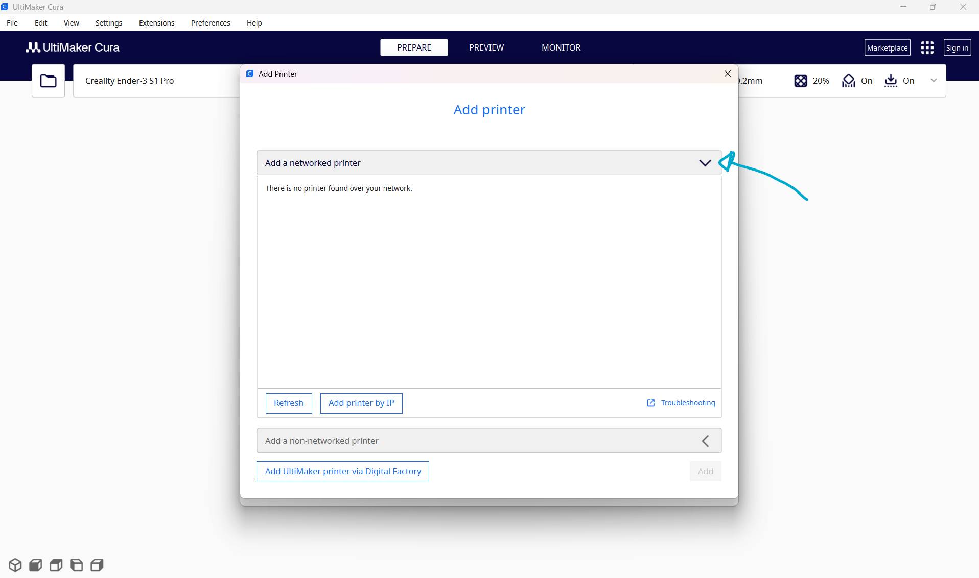
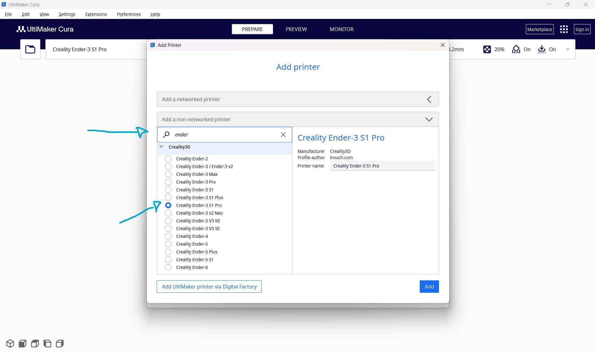
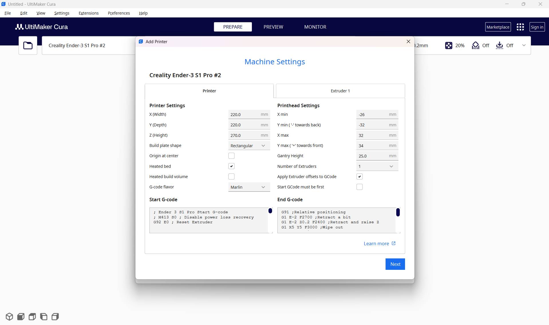
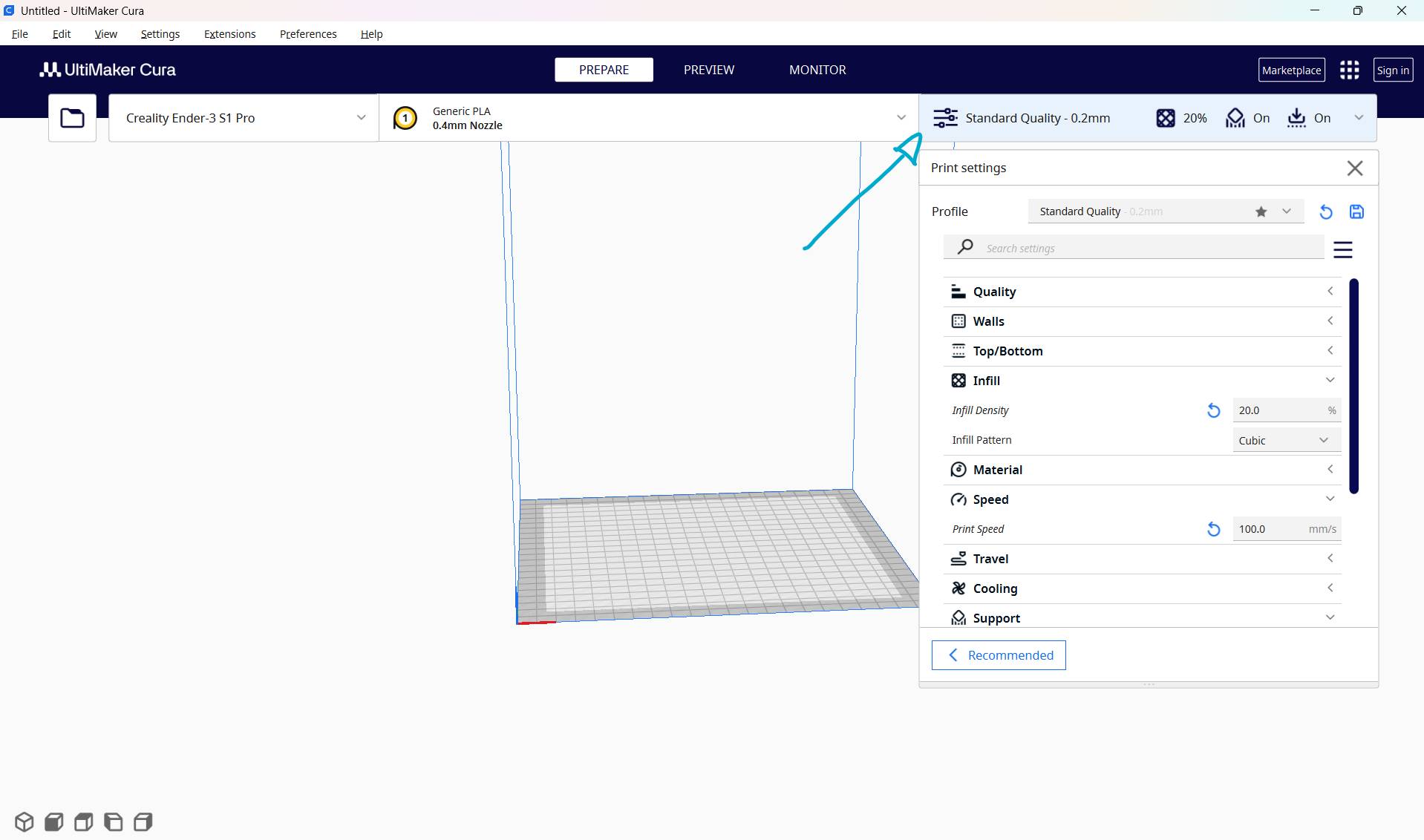
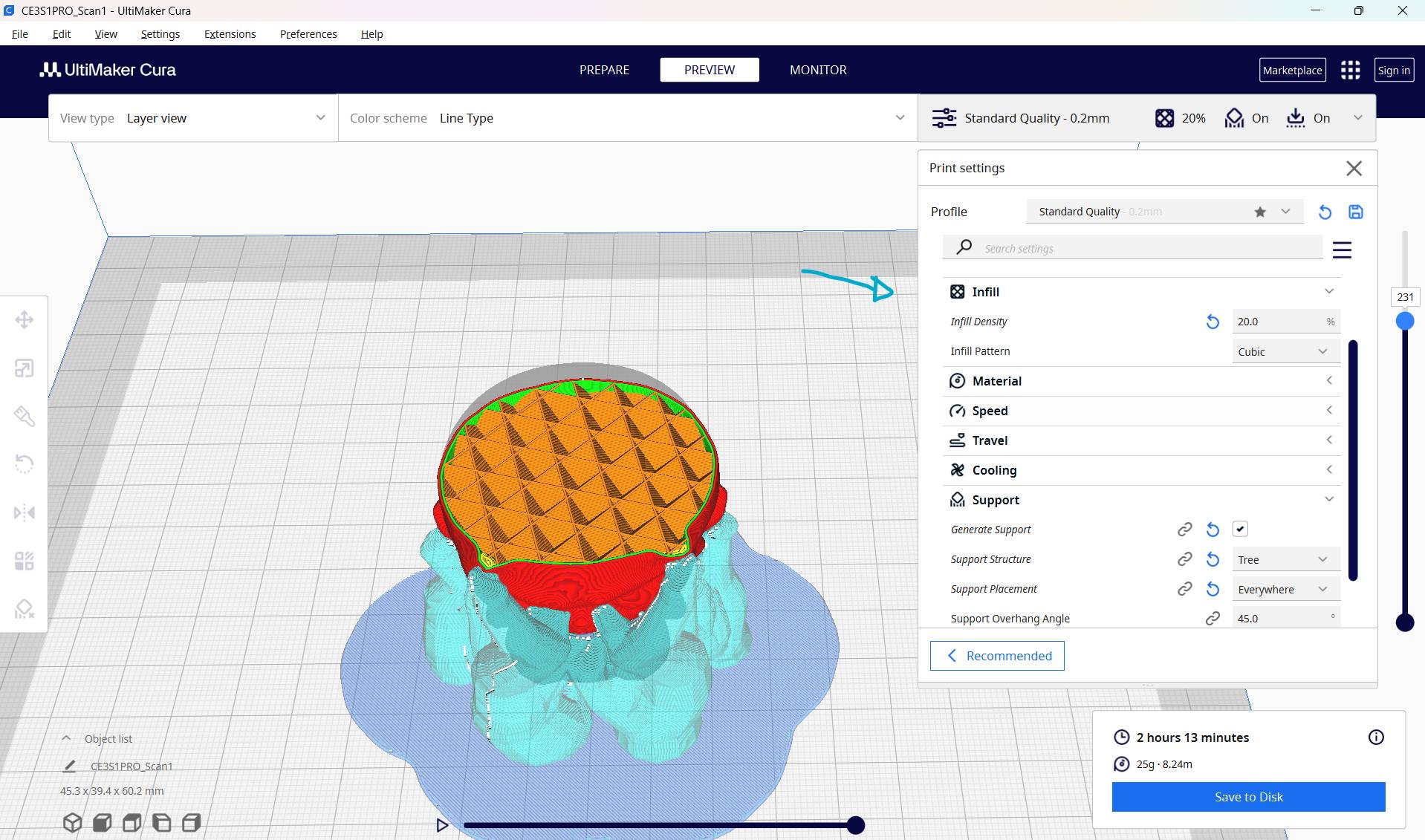
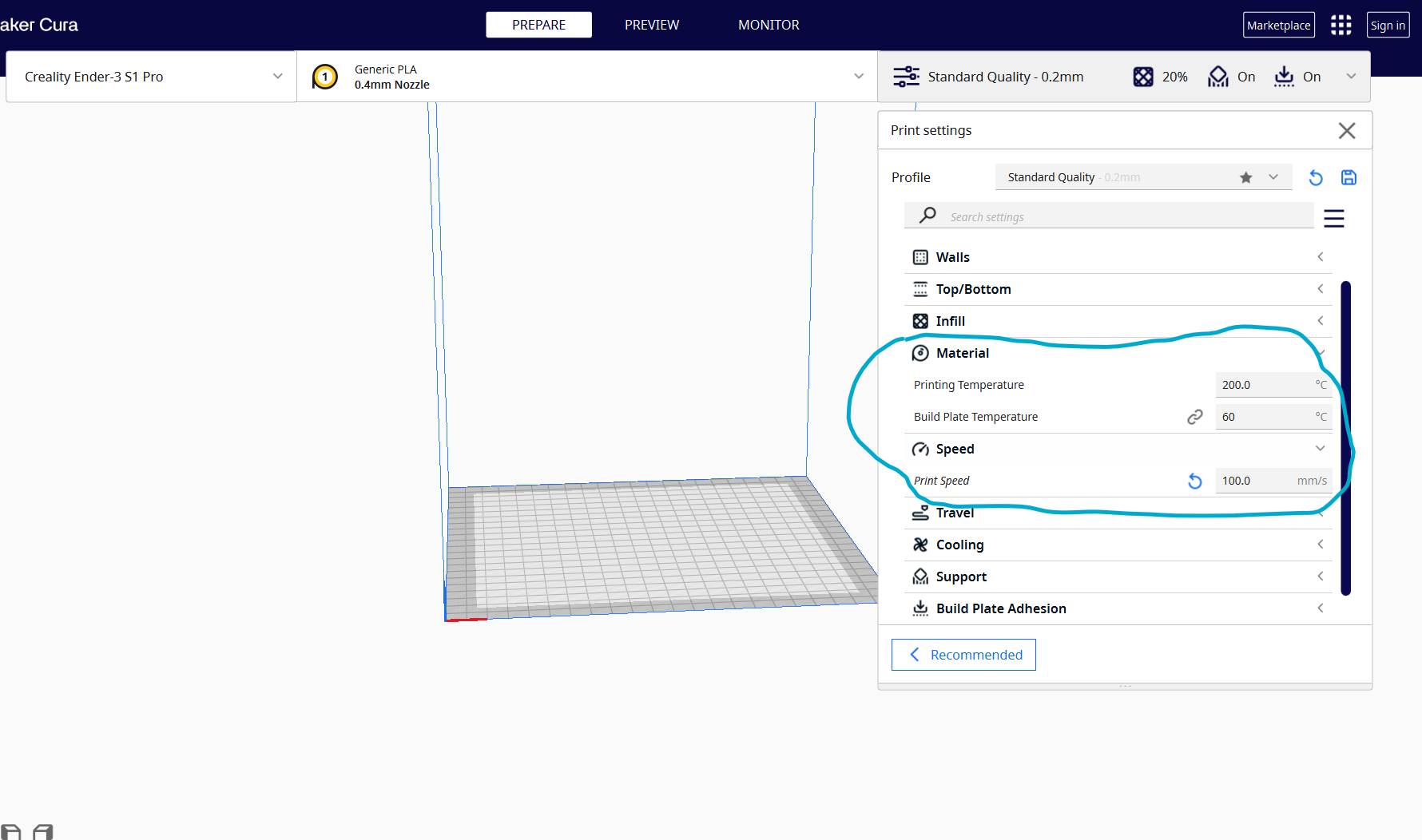
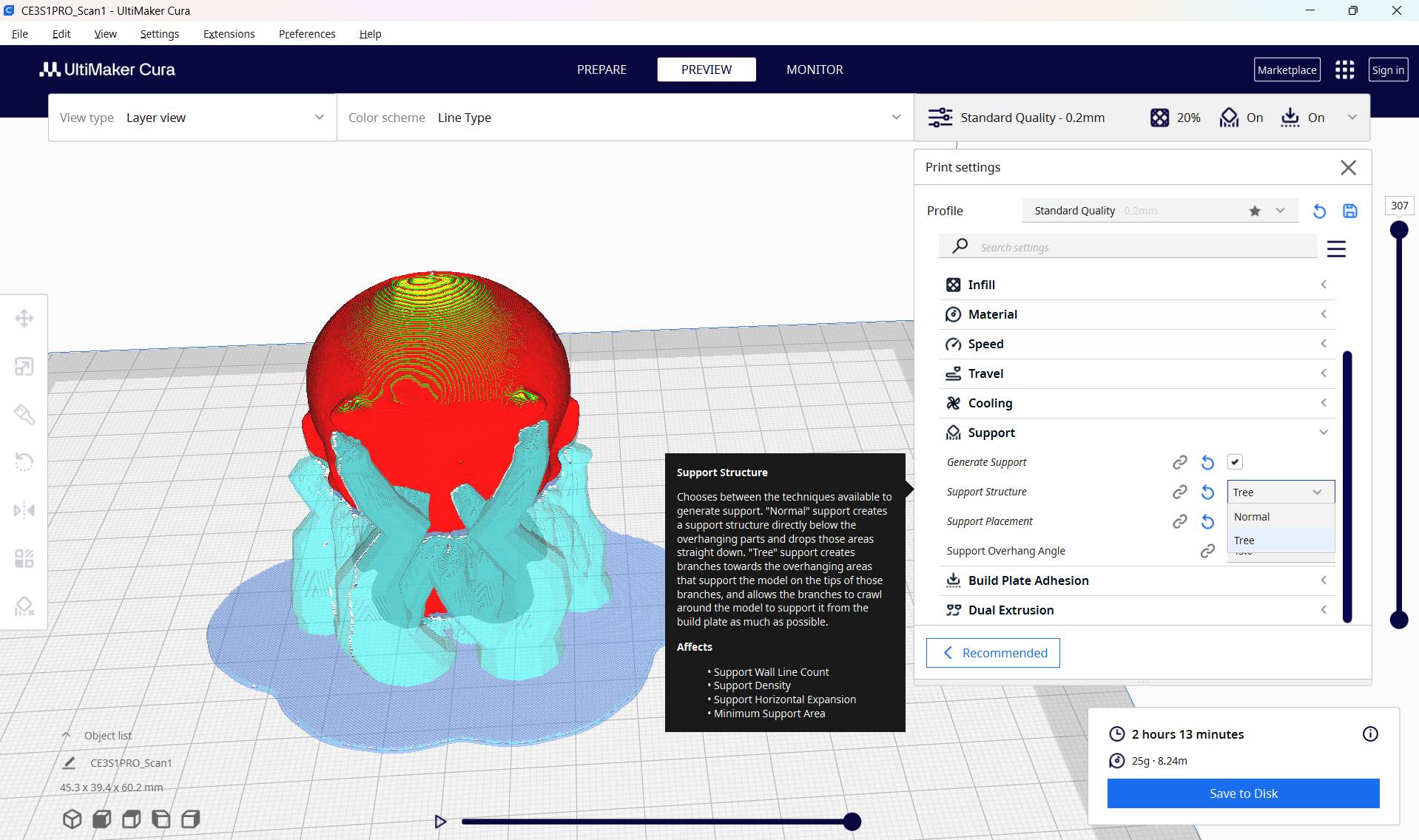
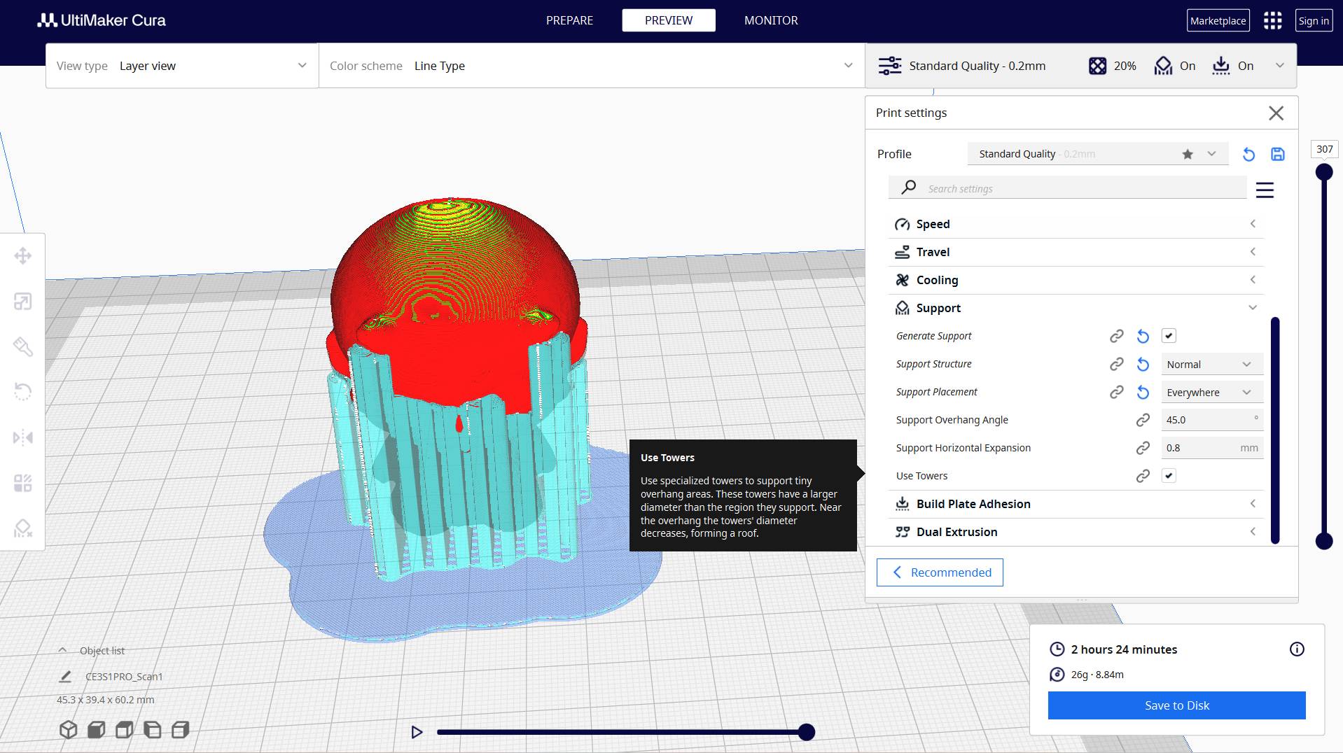
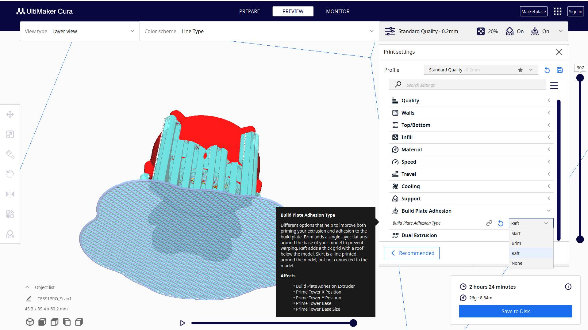
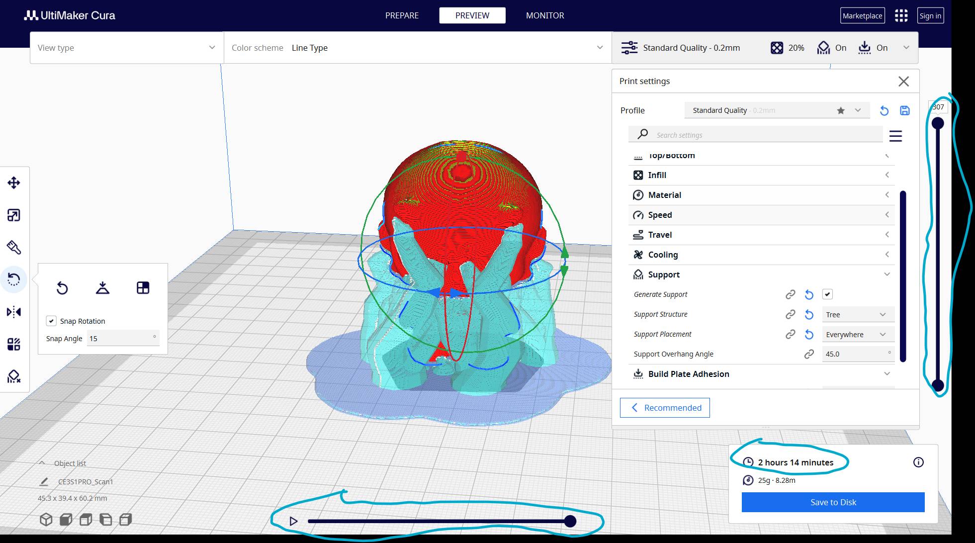
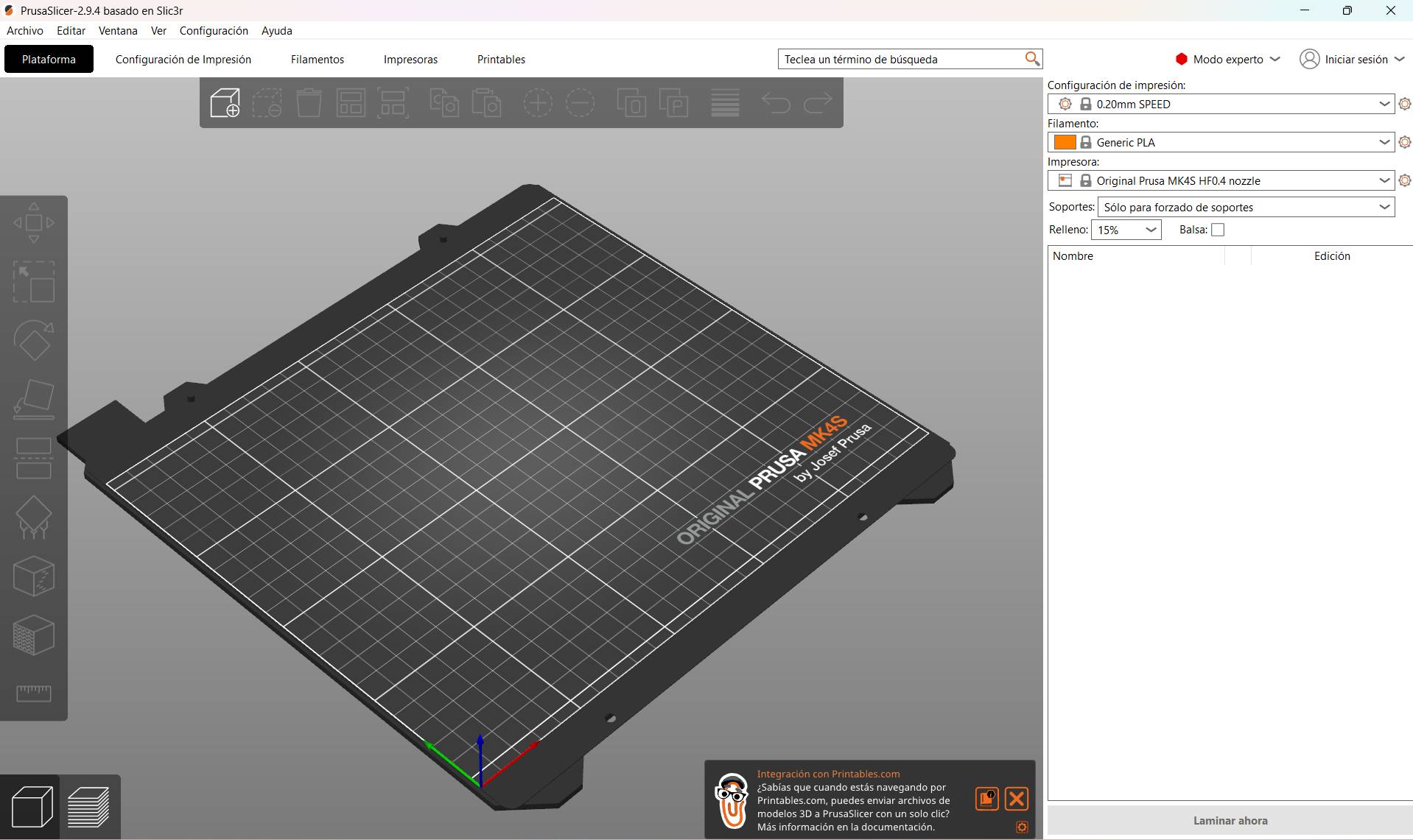
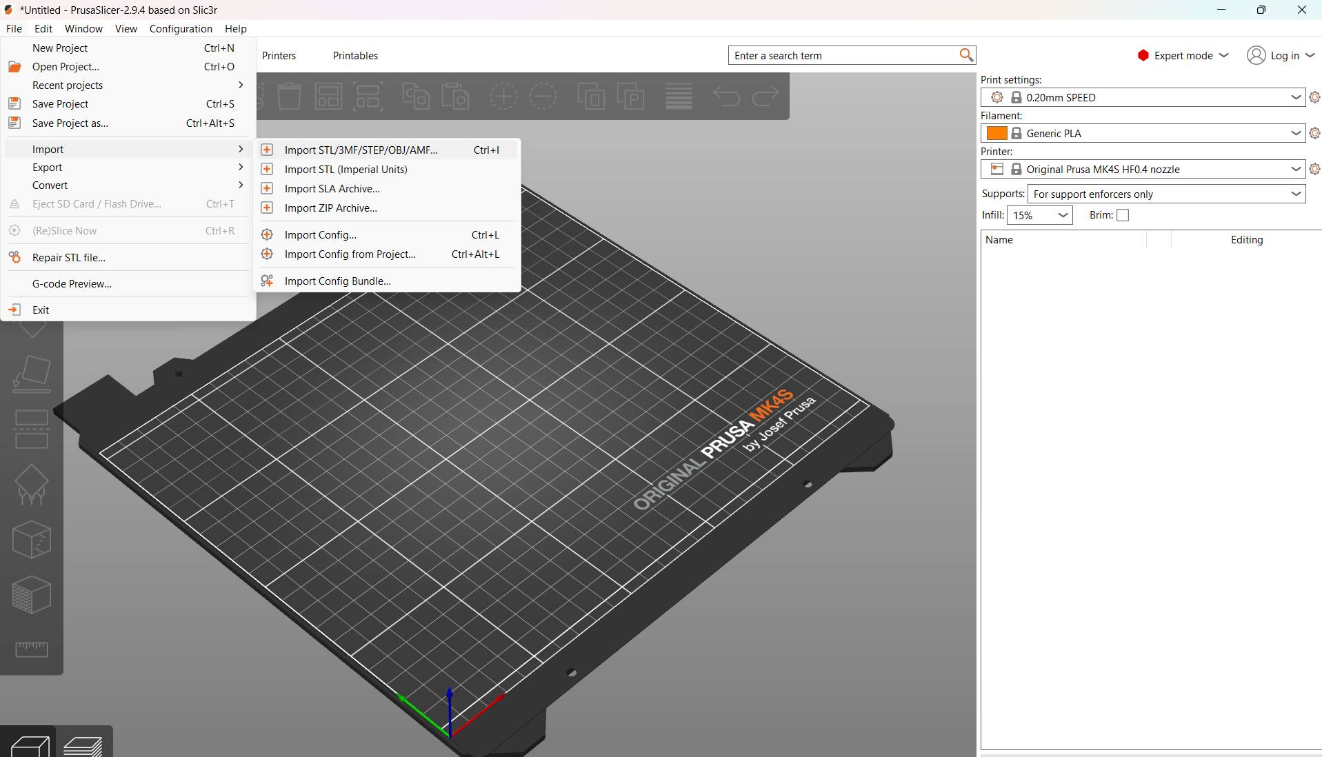
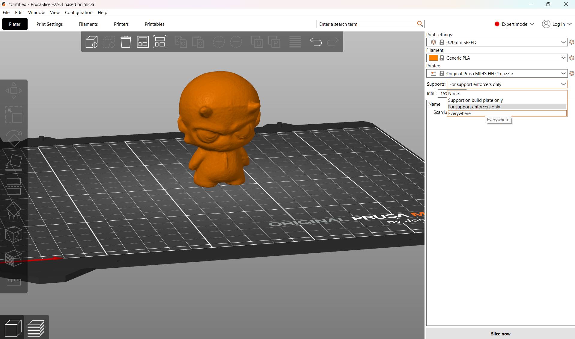
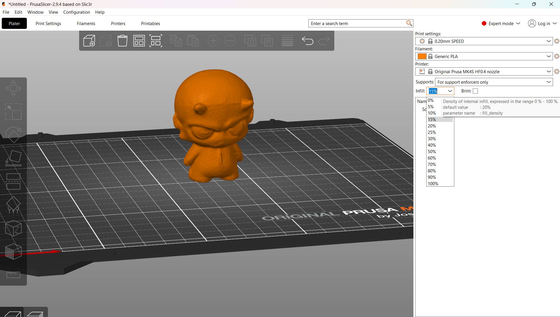
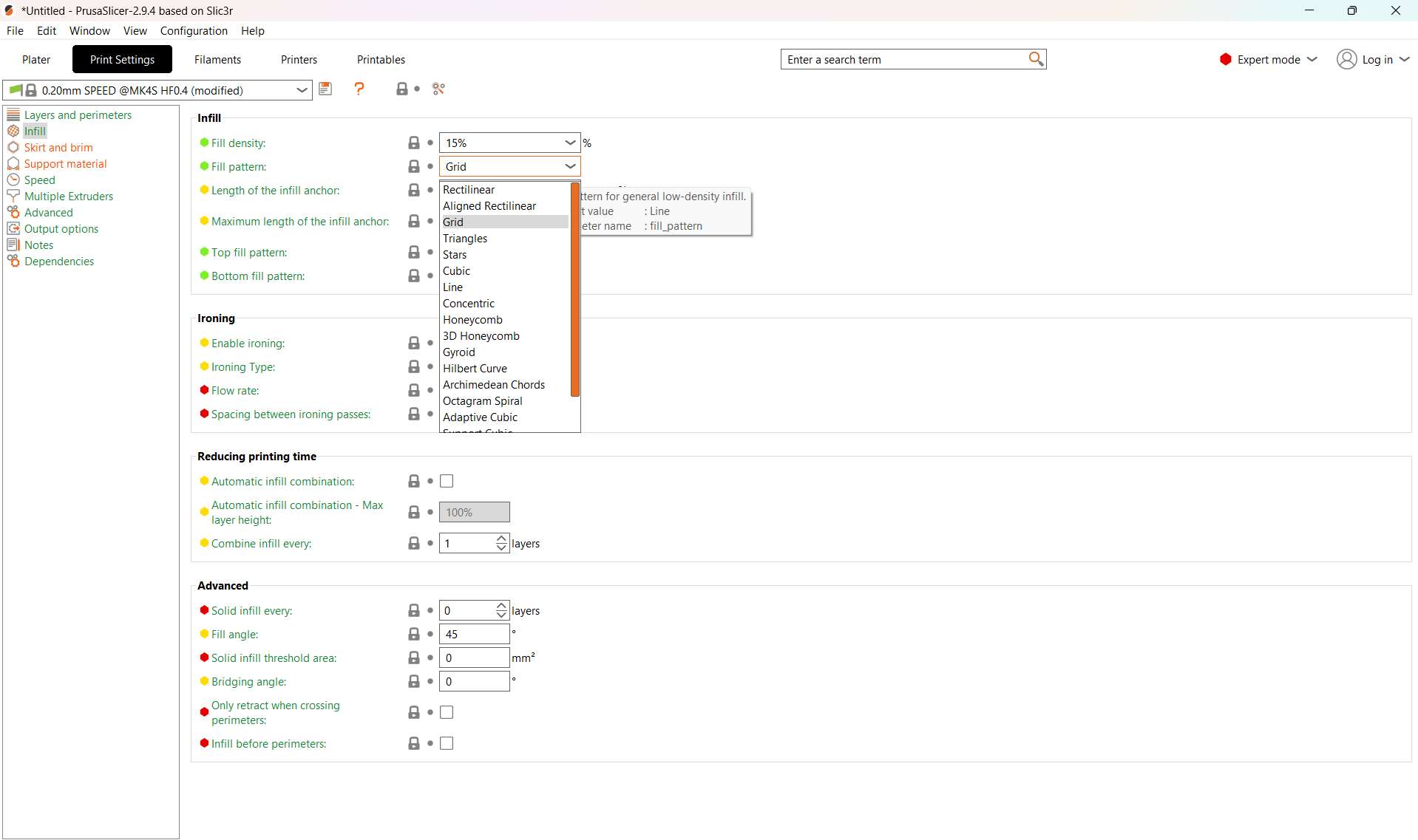
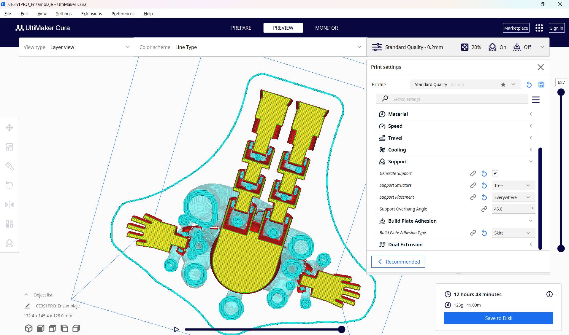
Once your scan is exported to STL, you can import it into 3D printing software such as Ultimaker Cura to prepare your file for the printer.
[ FINAL RENDER: MISSION ACCOMPLISHED ]
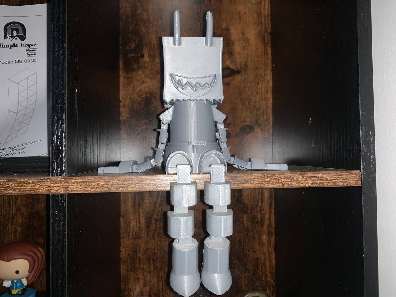
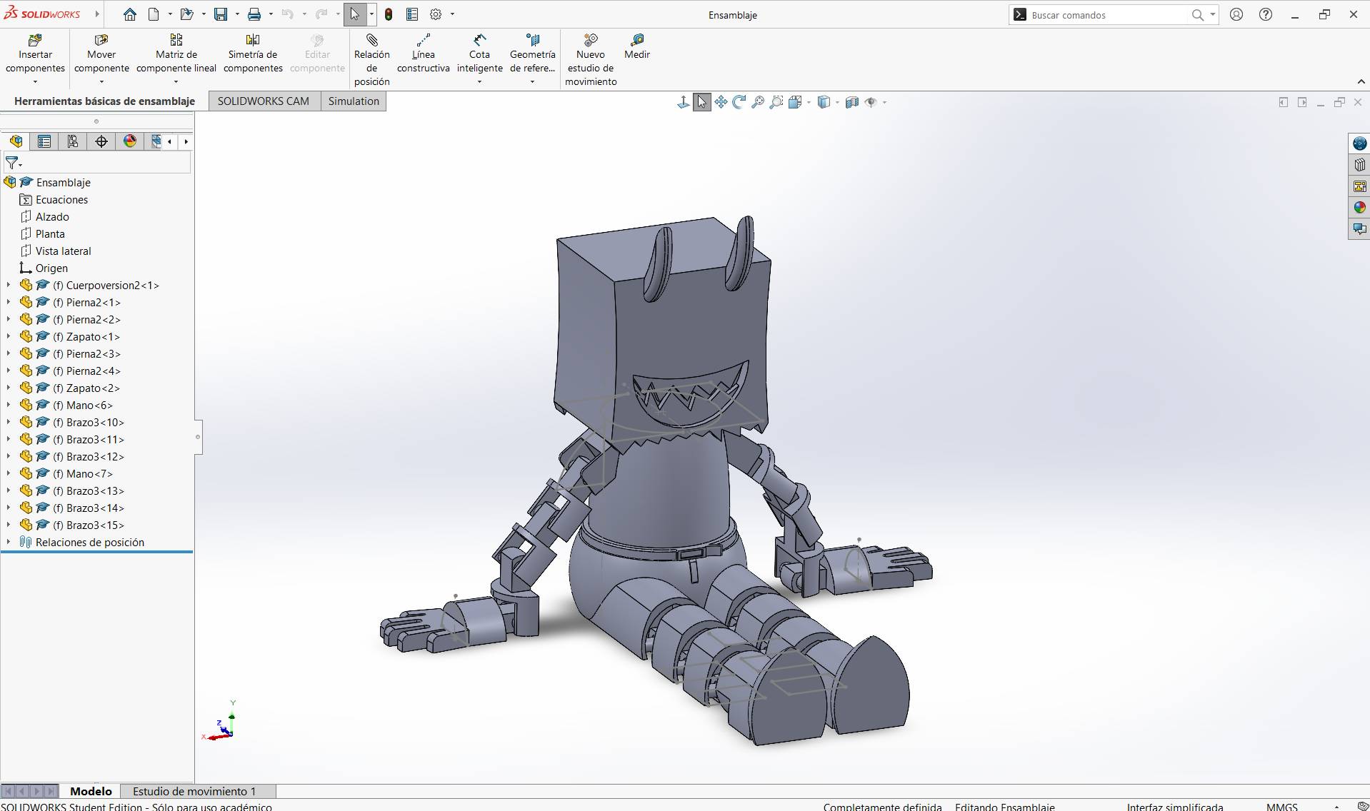
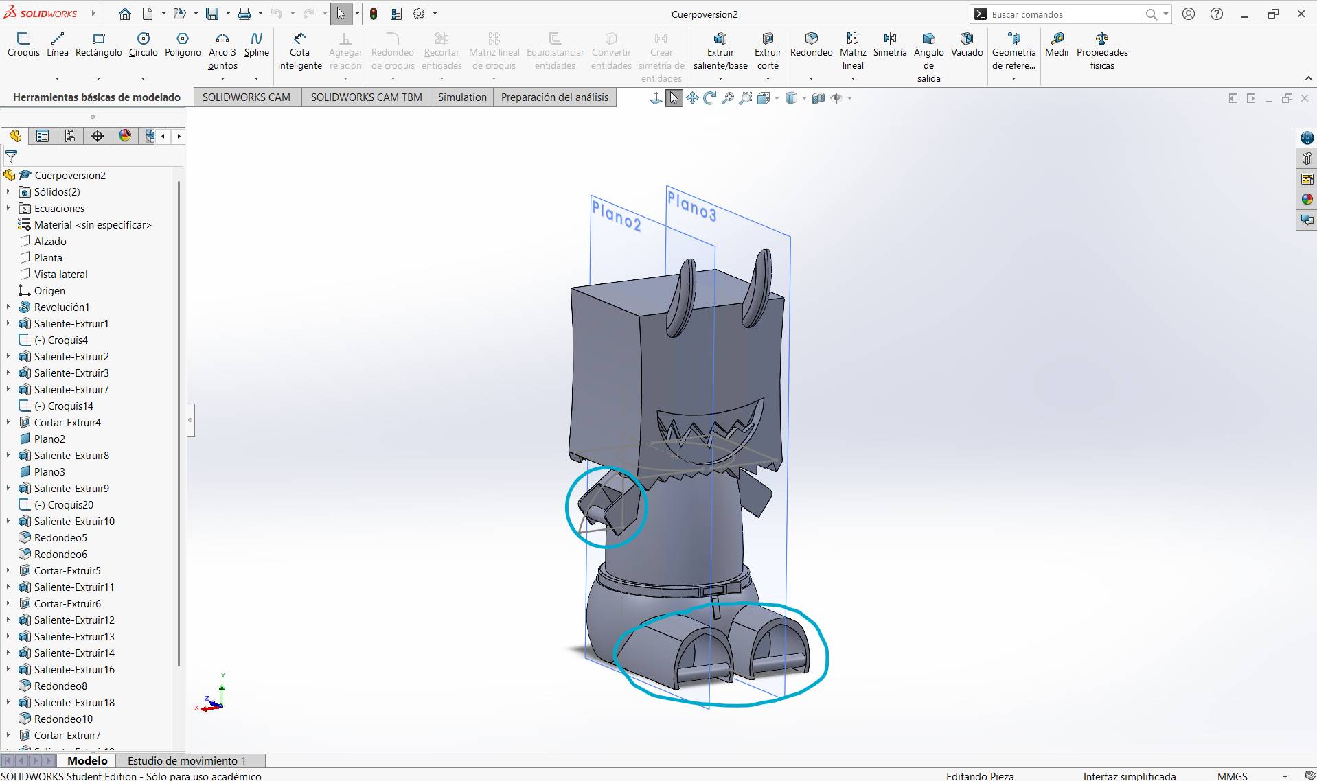
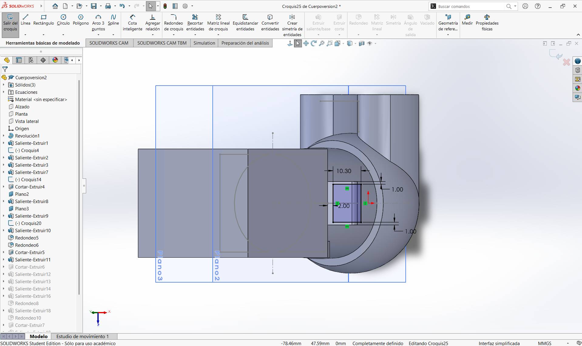
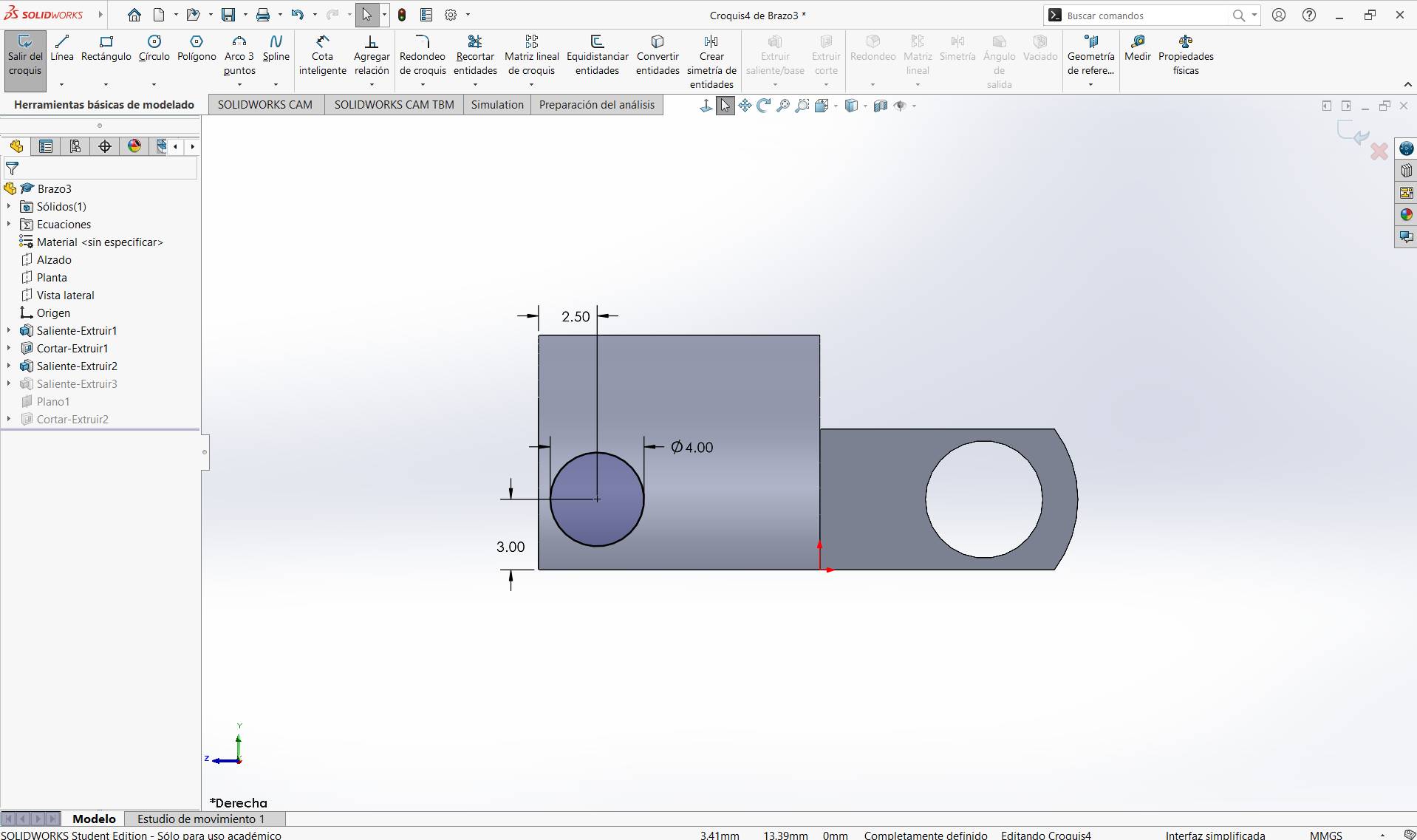
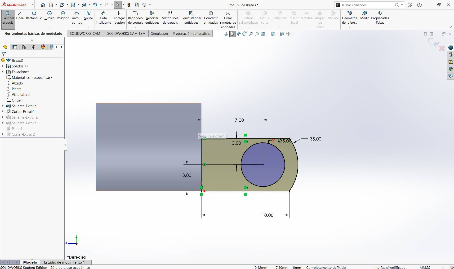
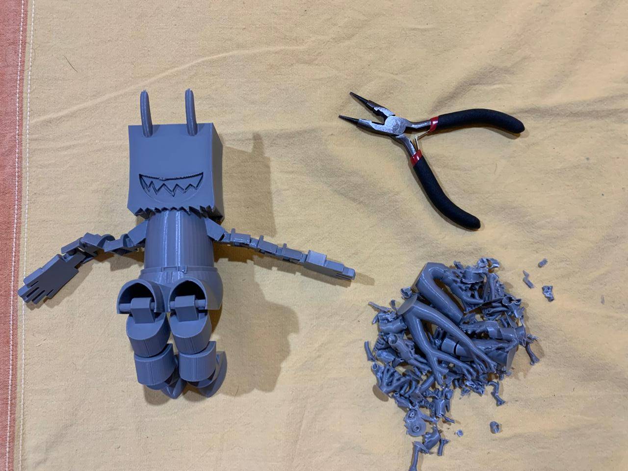
ARTICULATED TOY
Final assembly of the articulated toy. All joints are functional with a 1.2mm tolerance, allowing smooth movement while maintaining structural integrity.
STATUS: 100% READY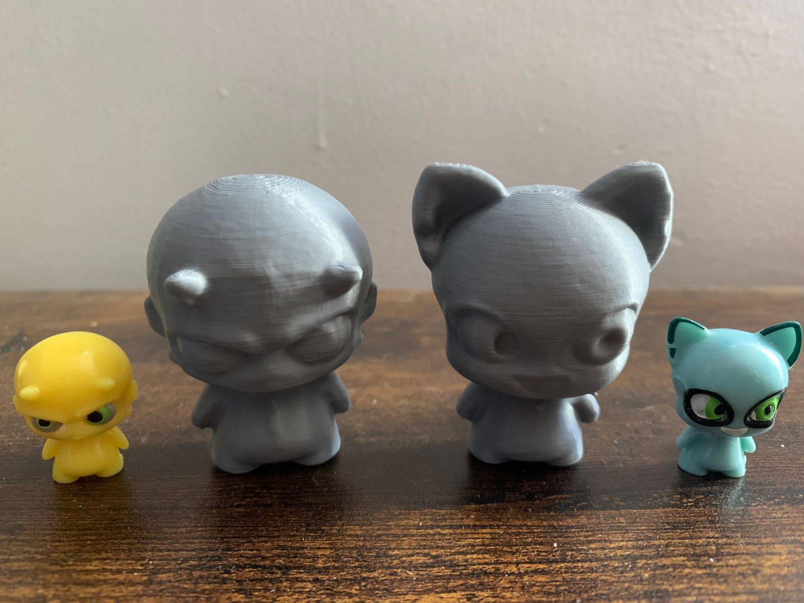
SCANNED IMPRESSION
Detailed view of the second printed mission,made out of a scanned toy (Funky Punky 2023 Vuala edition).
STATUS: 100% READY[ 3D PRINTER MODELS ]
| Printer | Kinematics / Architecture | Build Volume (X×Y×Z, mm) | Build Plate Area (X×Y, mm) | Z Height (mm) | Volume (L) | Machine Dimensions (mm) | Net Weight (kg) | Layer Height (mm) | Filament Diameter (mm) | Included Nozzle |
|---|---|---|---|---|---|---|---|---|---|---|
| Creality Ender-3 S1 Pro | Cartesian (bed-slinger) | 220 × 220 × 270 | 220 × 220 | 270 | 13.07 | 490 × 455 × 625 | 8.6 | 0.05 – 0.40 | 1.75 | 0.4 mm |
| Original Prusa MK4S | Cartesian (bed-slinger, open-frame) | 250 × 210 × 220 | 250 × 210 | 220 | 11.55 | 500 × 550 × 400 | 7.0 | 0.05 – 0.30 | 1.75 | 0.4 mm (High-flow Prusa Nozzle brass CHT) |
| Original Prusa XL | CoreXY | 360 × 360 × 360 | 360 × 360 | 360 | 46.66 | 700 × 900 × 720 | 27.9 (1 tool) / 29.3 (2 tools) / 33.7 (5 tools) | 0.05 – 0.30 | 1.75 | 0.4 mm (Prusa Nozzle brass) |
| SeeMeCNC Rostock MAX v3 | Delta (vertical tower architecture) | Ø265 × 400 | Ø265 | 400 | 22.06 | 279 × 279 × 349 | 15 | 0.10 – 0.40 (recommended) | 1.75 | 0.5 mm |
[ TYPES OF FILAMENTS ]
| Material | Description | Printing Temperature | Advantages | Disadvantages | Hardware Requirements |
|---|---|---|---|---|---|
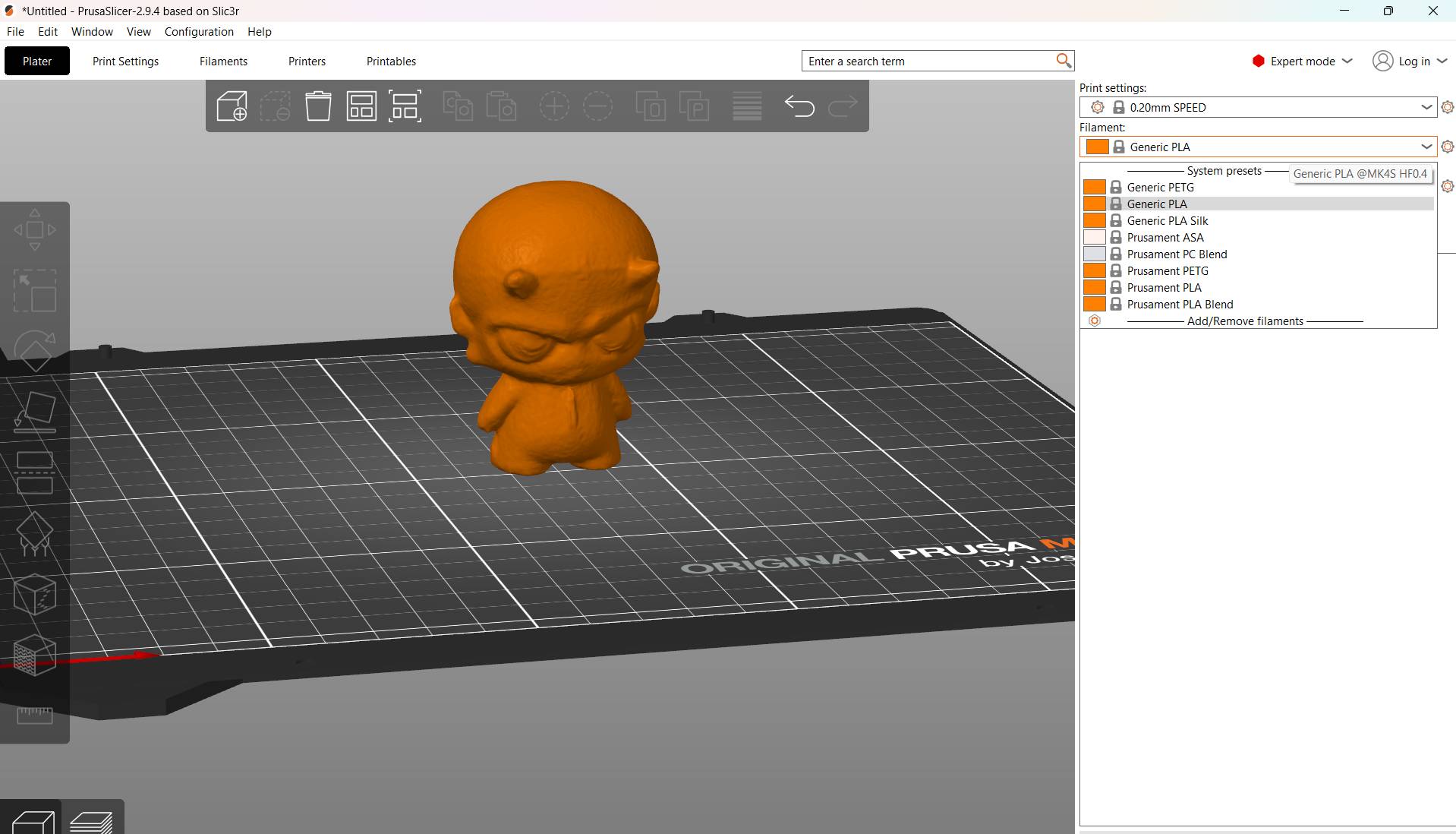
| PLA | A biodegradable thermoplastic derived from renewable resources like corn starch. It's the standard for desktop printing due to its minimal thermal expansion. | Extruder: 190-220 °C Bed: 50-60 °C |
Easy to print, low cost, rigid, and great surface detail. | Brittle, low heat resistance (deforms above 60°C). | Standard FDM printer. |
| ABS | A petroleum-based thermoplastic known for its impact resistance and toughness. Allows post-processing with acetone for a smooth finish. | Nozzle: 230-250 °C Bed: 80-110 °C |
Impact & wear resistant, durable, and affordable. | Prone to warping (shrinkage), emits unpleasant fumes. | Heated bed and enclosed chamber recommended. |
| PETG | The "middle ground" material. It combines the ease of use of PLA with the functional strength and chemical resistance of ABS. | Nozzle: 230-250 °C Bed: 70-80 °C |
Excellent mechanical properties, water-resistant, and recyclable. | High "stringing" (hairs), can stick too well to the bed. | Standard FDM printer. |
| Nylon | A high-performance semi-flexible polymer. Offers the best combination of strength, compliance, and fatigue resistance for mechanical parts. | Nozzle: 240-260 °C Bed: 70-100 °C |
Extremely tough, low friction, and high chemical resistance. | Highly hygroscopic (absorbs moisture), difficult bed adhesion. | All-metal hotend and dry storage required. |
| TPU / Flexible | A Thermoplastic Elastomer (TPE) that behaves like rubber. It can be stretched and compressed without losing its original shape. | Nozzle: 210-230 °C Bed: 20-60 °C |
High shock absorption, flexible, and very durable. | Hard to print with Bowden tubes, needs slow speeds. | Direct drive extruder preferred. |
| ASA | Alternative to ABS with improved weather resistance. Specifically designed to withstand UV radiation without degrading. | Nozzle: 240-260 °C Bed: 90-110 °C |
UV resistant, high impact and wear resistance. | Expensive, emits styrene fumes during printing. | Heated enclosure and ventilated area. |
| Composite (CF, Wood, Metal) | Base polymers (PLA/PETG) infused with fibers or powders to change their aesthetic or physical properties. | Variable (follows base material) | Unique finishes (wood/metal) or increased stiffness (Carbon Fiber). | Highly abrasive, can clog standard nozzles easily. | Hardened steel nozzle required. |
PRINTING FILES
Download the toy that I made.