Week_03:
Computer controlled cutting
This week I worked on defining my final project idea and started to getting used to the documentation process.
assignment group assignment: characterize your lasercutter’s focus, power, speed, rate, kerf, joint clearance and types individual assignment: cut something on the vinylcutter design, lasercut, and document a parametric construction kit, accounting for the lasercutter kerf, which can be assembled in multiple ways, and for extra credit include elements that aren’t flat
Individual Assignment: parametric kit
I as I’m sure many of my fellows with whom I share in this Fabacademy quest enjoy and have been fascinated and at times captured by the creation and evolution of the artform of Video Games. The ability to create a alternate universe fabulous and strange with technology that we dream of in today’s current era is one of the factors that led me to this attempt to seek the tools that the Fabacademy gives us which we can then go on and create and innovate.
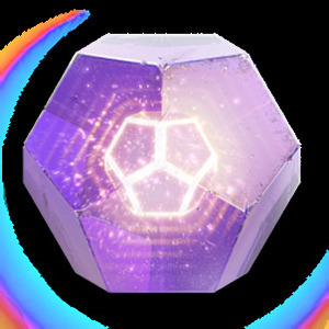
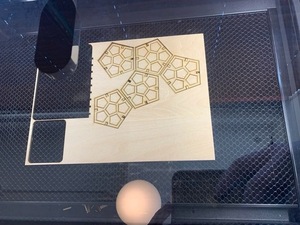
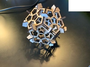
One of the games which has taken up alot of my attention (which I am sorely missing due to having to allocate extra study hours) Is Bungie studios’s Epic; “Destiny”. In the game loot drops are contained in these “engrams” of which you can see an example above. They are pentagonal dodecahedrons and i think this can serve as a great basis for my parametric kit as I think if you have enough of these pentagon shapes and can pressfit them together in different ways they could make a fun toy to tinker with.
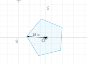
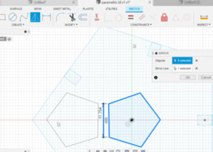
And so we begin. I attempted to use Cuttlexyz but found it a bit clunky so I went back to old faithful Fusiom 360. We start by making a simple pentagram and I decided on a radius of 35mm as its a handy size and would allow for me to cut the 12 necessary sides from a single sheet of our 3mm plywood base.
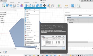
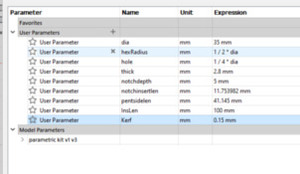
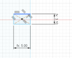
I then used the change arameters function to add the vaious parameters of the shape that I would be using such as thickness, diamete, side length etc which would all assist me in designing the rest of the shape.
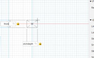
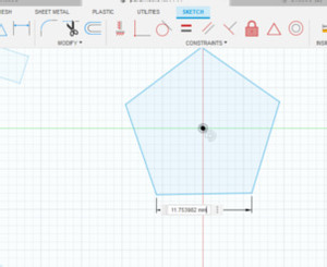
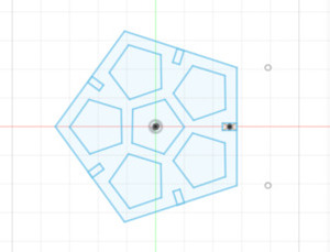
I used the parameters to design the cut outs for the sides of the pentagon and then used the pattern function to arragnge the notches in the middle of each side of the pentagon.
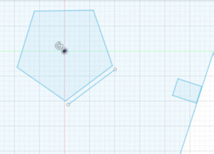
In an attempt not to waste material I would cut out the connecting pieces from the center of the shape. I created a smaller pentagon in the center using twice the depth of the notches in the sides as defined in my parameters, and using the dimentions tool projected the side length out created two points and drew a line.
I used this line to create a mirror of the pentagon far enough away from the central pentagon so as not to compromise the strength of the overall kit.
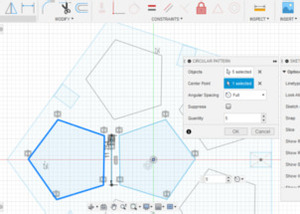
I then used the pattern function again to create multiple copies of the cutout and made a cool design.
I then added a Kerf to my parameters.
Checked that it was reflecting accurately on my notch design.
And the design was complete.
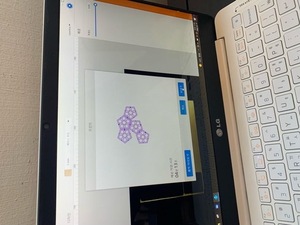
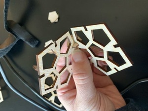
cutting the design
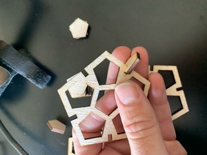
Assembly
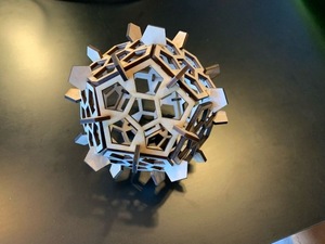
Final product
Individual assignment: Cut something on the Vinyl cutter

Being the mega creative genius that I am. I chose to cut the logos of all the things involved in this Fab Academy journey. Starting with the Fab Lab logo.
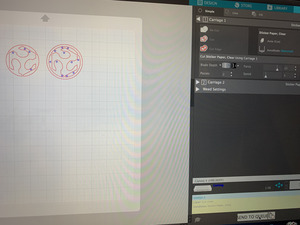
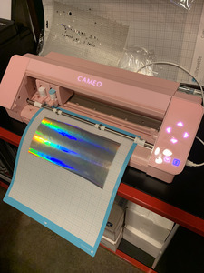
We have an awesome pink Sillohette Cameo here at the BOLD Lab, and the great thing about the Sillouhette is the extremely user friendly software which is free to download and use. I imported the image and used the trace function to create a vector for cutting.
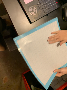
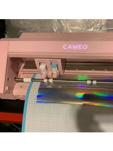
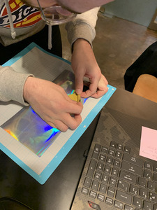
Next we need to fix the material we want to cut to the flexible base. Obviously, the shinier the better.
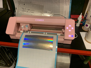
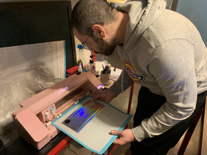
Next we let the machine do it’s magic.
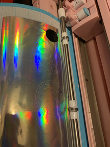
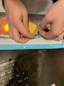
I found it a bit challenging removing the cut out shape from the adhesive backing without damaging the finer cuts. Once I had removed the design I had three pieces that were loose and there was no way I could stick them on as perfectly as they were cut.
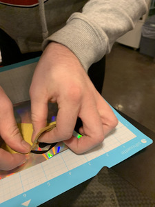
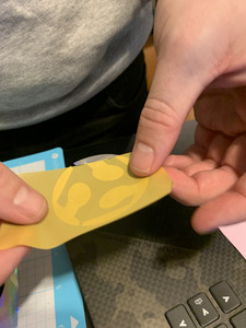
I took some masking take and used it as a medium to transfer the stickers we just cut.
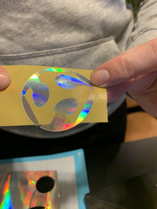
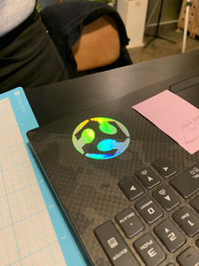
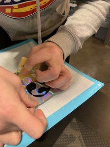
It proved extremely helpful as we were able to both remove the sticker without any damage but also transfer it to the intended surface of my laptop while keeping the design perfectly aligned.Group Assignment
Formshop Fab Lab 2026 group member: Yaro, James, Winnie, Yanfeng and me
Safety training
We are using a **Thunder Laser** DC CO2 glass tube laser system for this week's cutting and engraving tasks. Safety training is essential before operation, as the laser can easily cause fires and generate smoke.
On the top of the machine, there is a large red emergency stop button, which should be pressed immediately in case of any danger.

Both the cooling system and the air extractor must be turned on during the entire working period.

Lasercutter sample making
Before cutting, we need to run a test sample to determine the appropriate settings (speed and power). This time, we selected 2mm plywood, 2.5mm acrylic, 0.7mm fabric, and 4mm cardboard for the test.
Operation process:
- Power check: Ensure the main switch, laser switch, cooling system, and air extractor are all turned on.
- File check: Draw the cutting paths in the software, confirm the speed and power settings, then send the file to the laser cutter. Adjust the cutting sequence and parameters layer by layer as needed.
- Material check: Measure the material thickness using the calliper.
- Material Fixing: Secure and flatten the material firmly using strong magnets in cutting area.
- Laser Focusing: Use a gauge to set a 6mm gap between the material surface and the laser head.
- Set Origin: Move the laser head to the desired starting position, then press the "Origin" button to set it.
- Frame Check: Press the "Frame" button to preview the cutting area and verify the pattern size.
- Close Lid: Securely close the machine's protective lid.
- Begin Cutting: Press the “Start” button to start the cutting process.

Material Testing Matrix Generator
The optimal power and speed settings follow a key principle: use the maximum speed achievable with the minimum power required. This approach balances processing efficiency with the long-term preservation of the machine.

We can pre-set the parameter and save as a default setting.

This is a control panel that help us visually check.

To adjust the focus, first loosen the screw with one hand while supporting the laser head with the other to prevent it from dropping. Then, insert a 6mm gauge between the material and the head to set the gap. Finally, tighten the screw to secure the head and press the "Origin" button to confirm the position.

Zero the calliper and measure the thickness of material.


We tested cutting parameters for plywood, acrylic, corrugated paper, and fabric. The optimal settings for each material are listed below :
Note: Due to variances in material batches, storage, and equipment, the following parameters are reference values and may require adjustment.
- 2mm Plywood: Speed = 70 mm/s, Power = 80 %.
- 0.7mm Fabric: Speed = 94 mm/s, Power = 19 %.
- 4mm Corrugated Paper (3 layers): Speed = 48 mm/s, Power = 49 %.
-
2.5mm Acrylic Board: Speed = 18 mm/s, Power = 84 %.


Warning: Fire Risk with Corrugated Paper
This material is prone to ignition. Never leave the laser unattended during cutting. Keep a fire blanket or extinguisher accessible. If fire occurs, stop the machine immediately and extinguish the flames.
Caution: Thin Fabric Settings
The laser can easily burn through thin fabric. Always start with very low power or high speed settings, and conduct a test cut to fine-tune parameters.

Bend test
It’s surprising how much plywood can bend! The flexibility really depends on the pattern you use.

Joint test
For 2mm Plywood, the joint width is best between 1.65mm~1.70mm

Kerf test
Kerf: 100.6mm-100mm=0.6mm, Kerf=0.6/11=0.055mm

Material Template
The Template include: Text size, Engraving test, bend test, through test.
Cut testing result


Photo from Yaro
Testing Sample Documents
When importing an .SVG file into LaserMaker, the dimensions may occasionally be inaccurate. For improved reliability, you may also import the design using the .DXF file format.
Note: Measure the dimensions in LaserMaker before cutting.
Lasermaker files (with setting)
SVG files
- Bend_test.svg
- Joint_test.svg
- Kerf_test.svg
- Material_template.svg