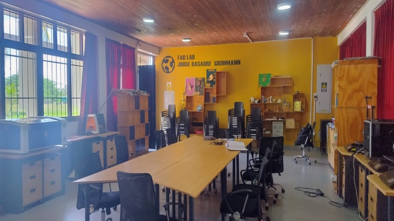
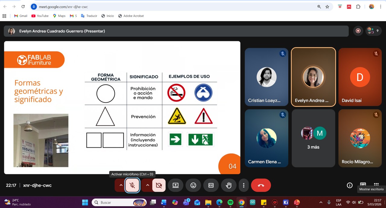
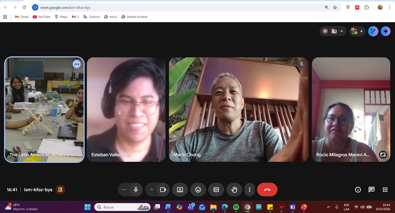
The group training on workplace safety measures in a FabLab was carried out through a virtual meeting and was led by Evelyn Cuadrado, manager of FabLab iFurniture. During the session, the specialist clearly and dynamically shared her experiences and knowledge related to working with computer-controlled machines, especially those intended for CNC milling and cutting.
The talk was very enriching, since it made it possible to understand the importance of occupational safety and health in the use of specialized machinery. Likewise, the main safety measures that must be followed within the laboratory were addressed, such as the proper use of personal protective equipment (PPE), procedures to prevent accidents, and safe practices when operating machines.
The importance of maintaining a safe work environment was also highlighted, as well as the ability to identify possible risks or hazards within the workspace. During the reflection after the training, it was identified that some of these safety measures have not yet been implemented in the FAB LAB laboratory of Instituto Jorge Basadre. However, this training has made it possible to recognize their importance and the need to apply them.
Based on the knowledge acquired in this training, I commit myself to actively collaborate to promote and implement these safety measures in the laboratory as soon as possible, in order to improve working conditions and strengthen accident prevention.
This type of training activity contributes significantly to strengthening a culture of safety, responsibility, and prevention within the work environment.
Img 1
Img 2
Img 3
Img 4
A summary of the topics covered in the talk is presented below:
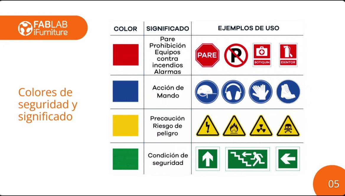
Safety signs:
Red: Indicates danger or emergency situations, such as machine stop or activation of protection measures.
Blue: Represents mandatory actions, such as the use of personal protective equipment (PPE).
Yellow: Indicates precautions or warnings, such as dangerous or potentially hazardous areas.
Green: Means safe conditions or the presence of first aid equipment.
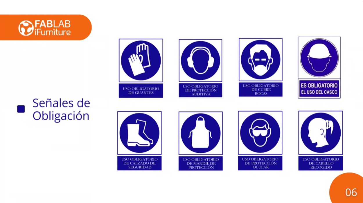
Personal Protective Equipment (PPE):
Img 5
PPE is essential to protect workers from possible risks. This includes gloves, helmets, safety glasses, boots, and masks, among others, depending on the task to be performed.
OCCUPATIONAL SAFETY AND HEALTH
Safety signage in the CNC milling area:
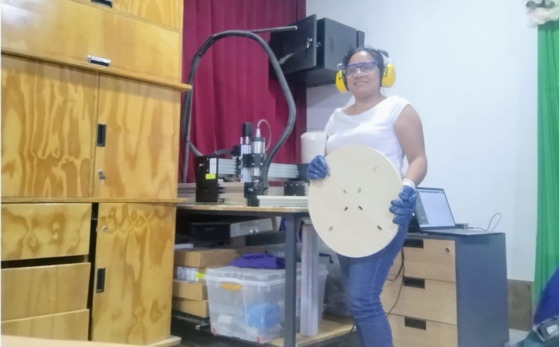
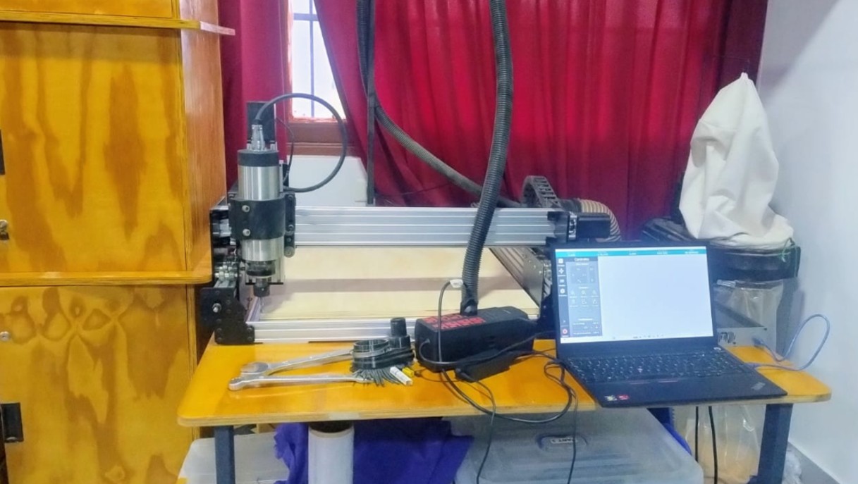
At Fab Lab Instituto Jorge Basadre Grohman, there is a CNC milling machine located in a spacious and well-ventilated area, designed to guarantee a safe and efficient work environment. After the safety training, I realized that many safety measures still need to be implemented.
Img 6
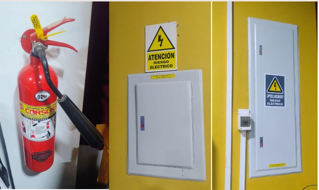
The signage currently available at the institute includes a fire extinguisher and electrical hazard signs. It is still necessary to implement evacuation signs and safety tapes in order to maintain a safe distance when the machines are operating.
Img 7
I carried out the test runout, alignment, fixturing, speeds, feeds, materials, and toolpaths for your machine with my classmates, but virtually, since I am in Madre de Dios and it was difficult for me to travel to Lima this time, which is where they meet to do the group work and which is 5 days away from Madre de Dios by land and 2 hours by plane. So I connected virtually with my classmates and then replicated the same process at the FAB LAB of IESTP Jorge Basadre Grohman.
Img 8
2. Introduction to the router
Computer-controlled machining (CNC, Computer Numerical Control) is a digital manufacturing process in which a machine tool is controlled by computer-programmed instructions. These instructions, generally written in G-code, tell the machine the precise movements it must make to cut, drill, or shape different materials.
In a digital fabrication environment such as a Fab Lab, CNC machining allows designs created in CAD/CAM software to be transformed into physical objects with high precision, repeatability, and efficiency. Unlike manual tools, CNC machines execute previously programmed exact paths, which reduces human error and makes it possible to manufacture complex parts.
This type of technology is widely used to work with materials such as wood, MDF, acrylic, plastics, and some metals, depending on the power and characteristics of the machine. In the educational context of Fab Academy, CNC machining allows students to understand the complete digital fabrication workflow: design → toolpath generation → machining → final part.
2. CNC used in the laboratory
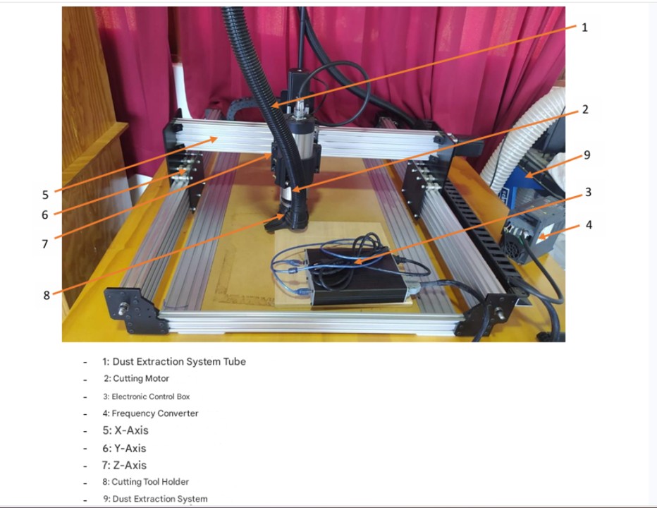
At the FAB LAB of Instituto Jorge Basadre, the Fox Screw S machine will be used, a CNC milling machine designed for digital fabrication, prototyping, and material machining processes in innovation and education laboratories.
According to the machine technical datasheet, the Fox Screw S has the following main characteristics:
Working area
The machine has a useful machining area of:
750 mm length
500 mm width
90 mm height
These dimensions allow working with medium-sized pieces, suitable for prototyping projects, small furniture fabrication, signage, or wooden structures and other materials.
Precision and structure
The CNC offers an approximate precision of ±0.05 mm, which is sufficient for digital fabrication work with a high level of detail. Its structure is built with a machined and assembled aluminum frame, which provides rigidity and stability during the machining process.
Motion system
The machine uses high-torque NEMA 23 stepper motors, which allow precise control of movement on the X, Y, and Z axes. These motors are common in educational and prototyping CNC machines due to their good relationship between precision, cost, and ease of control.
Tool power
The milling machine can work with tools up to 2.2 kW of power, which allows machining materials such as wood, MDF, plywood, plastics, and some composite materials.
Software and control
The machine works with G-code and is compatible with software such as:
Inkscape
Nomad Panel (machine control software)
The connection to the computer is made through a USB port, which facilitates its integration into the digital fabrication workflow.
Electrical system
The machine works with a power supply of 100–240 V AC (50–60 Hz) and has a Plug & Play electronic box, which simplifies its installation and use inside the laboratory.
Technical specifications of the Fab Lab iFurniture CNC router:
Specification
Detail
Model
Fox Screw S
Working area (X)
750 mm
Working area (Y)
500 mm
Working height (Z)
90 mm
Total machine length
1425 mm
Total machine width
1080 mm
Total height
390 mm
Tool power
Up to 2.2 kW
Machining precision
± 0.05 mm
Structure material
Machined and bolted aluminum frame
Motor type
High-torque NEMA 23 stepper motors
Control type
Numerical control through G-code
Compatible file formats
.gco, .gcode
Compatible software
Inkscape, Nomad Panel
Compatible operating system
Mac OS X / Windows XP and later
Connectivity
USB port
Energy consumption
100 W
Power supply
100 – 240 V AC, 50–60 Hz
Packaging dimensions
1150 × 870 × 430 mm
Package weight
80 kg
Warranty
2 years
Img 9
CNC machining workflow
The CNC machining process in the laboratory follows a digital workflow that goes from model design to the physical fabrication of the part. For this process, three main tools are used: Fusion 360, Aspire, and Nomad Panel, each with a specific function within the fabrication workflow.
1. Model design (CAD) – Fusion 360
The first step consists of designing the part in CAD software. For this stage, Fusion 360 is used, where the geometry of the part is modeled in 2D or 3D according to the project requirements.
At this stage, important aspects are defined such as:
Part dimensions
Material thicknesses
Assemblies or joints
Cutting or machining geometries
Once the design is finished, the file is exported in a format compatible with the CAM software, generally DXF, SVG, or STL, depending on the type of machining to be carried out.
2. Toolpath generation (CAM) – Aspire
After the design, the file is imported into Aspire, which is the software used to prepare the machining process.
At this stage, the following is defined:
Definition of material size (stock)
Selection of cutting tools
Cut depth configuration
Feed rate definition
Creation of toolpaths
The toolpaths indicate the movement that the milling bit will follow during machining. Once verified through simulation within the software, the file is exported as G-code, which contains the instructions that the CNC machine will interpret to execute the machining.
3. Sending and machine control – Nomad Panel
The G-code file generated in Aspire is loaded into the Nomad Panel software, which is the program used to control the Fox Screw S CNC in the laboratory.
From this software, the following operations are carried out:
Connect the computer to the machine via USB
Load the G-code file
Configure the origin point (X, Y, Z)
Verify the tool position
Start the machining process
Once the work is started, the machine automatically executes the programmed movements to cut or machine the material.
2.1 Machine alignment
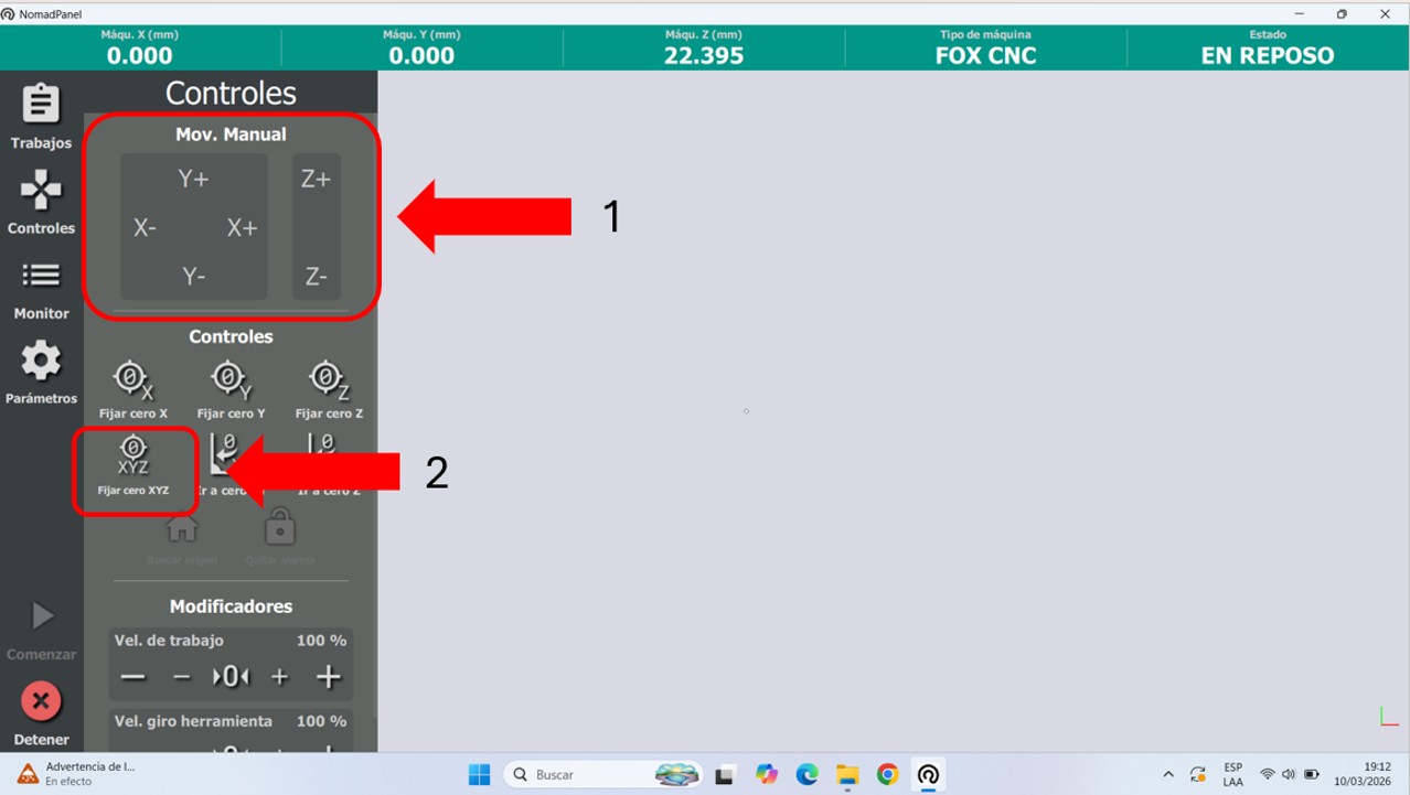
First, we connected the machine and opened the equipment software, in this case NOMAD PANEL. First, we went to controls and manually located the starting point. For this, we moved the machine on the X, Y, and Z axes. Once well positioned, we placed and fixed the origin point. This will be the reference point for the start of the work to be carried out. It must be considered that every time the machine is turned off and turned on again, or emergency stop is activated, the origin point must be fixed again.
Img 10
Img 11
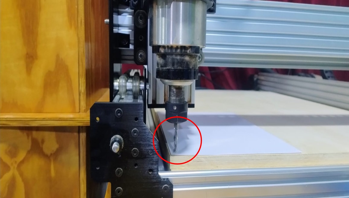
On the machine, the initial position where the bit starts the job can be seen. It is recommended to leave a Z height just above the thickness of a bond paper sheet as a reference.
Img 12
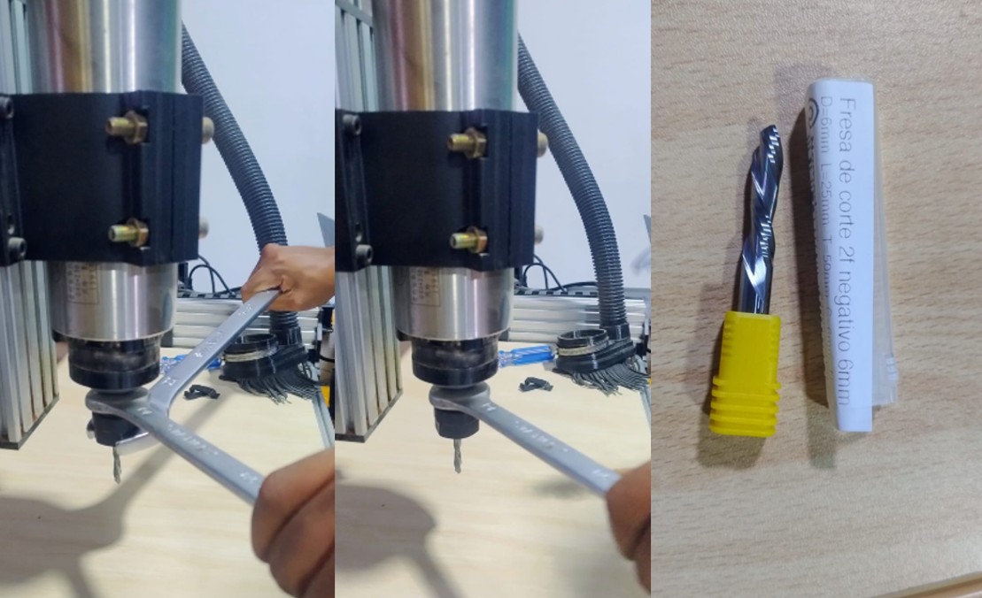
I also had to change the bit diameter because, since I worked with 15 mm plywood, the recommended bit diameter was 6 mm. For this I used two 30 mm x 401 mm combination wrenches, which are pushed in opposite directions in order to achieve a good adjustment.
Img 13
2.2 Design workflow in Fusion 360
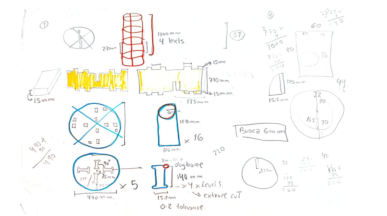
For the development of the real cutting tests, I used Fusion 360 to create my dogbone design and a comb test to study insertions. In my case, I worked with 15 mm plywood.
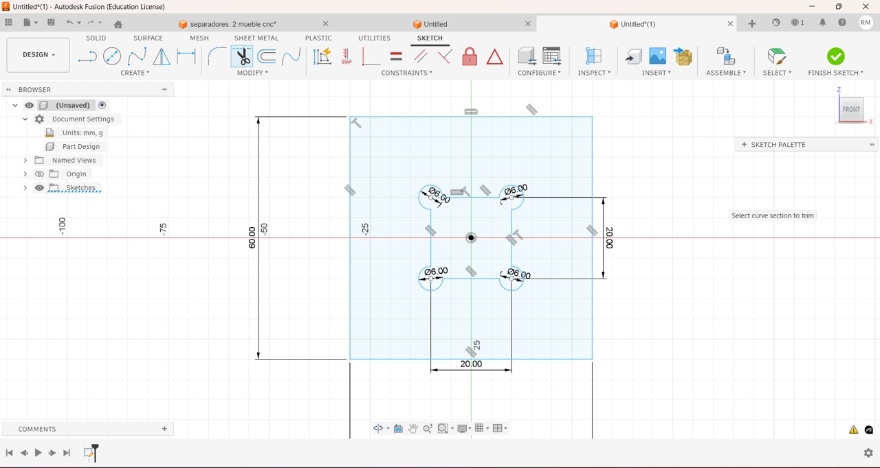
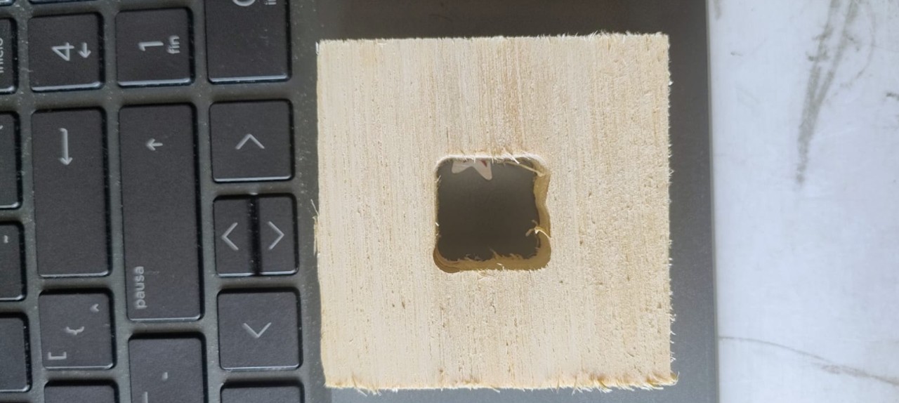
Img 14: I designed an external square of 6 cm by 6 cm, and inside, right in the middle, a smaller square of 2 cm by 2 cm. I also drew 6 mm diameter dogbones at each of the corners.
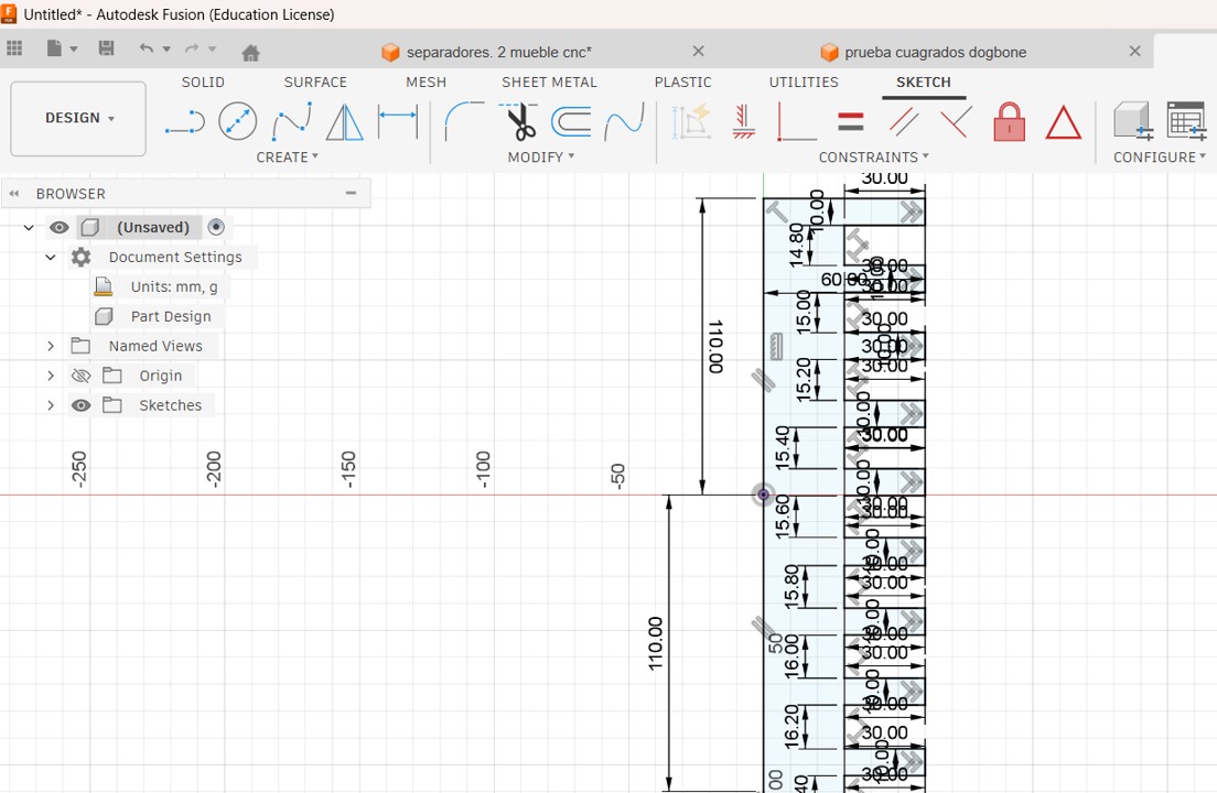
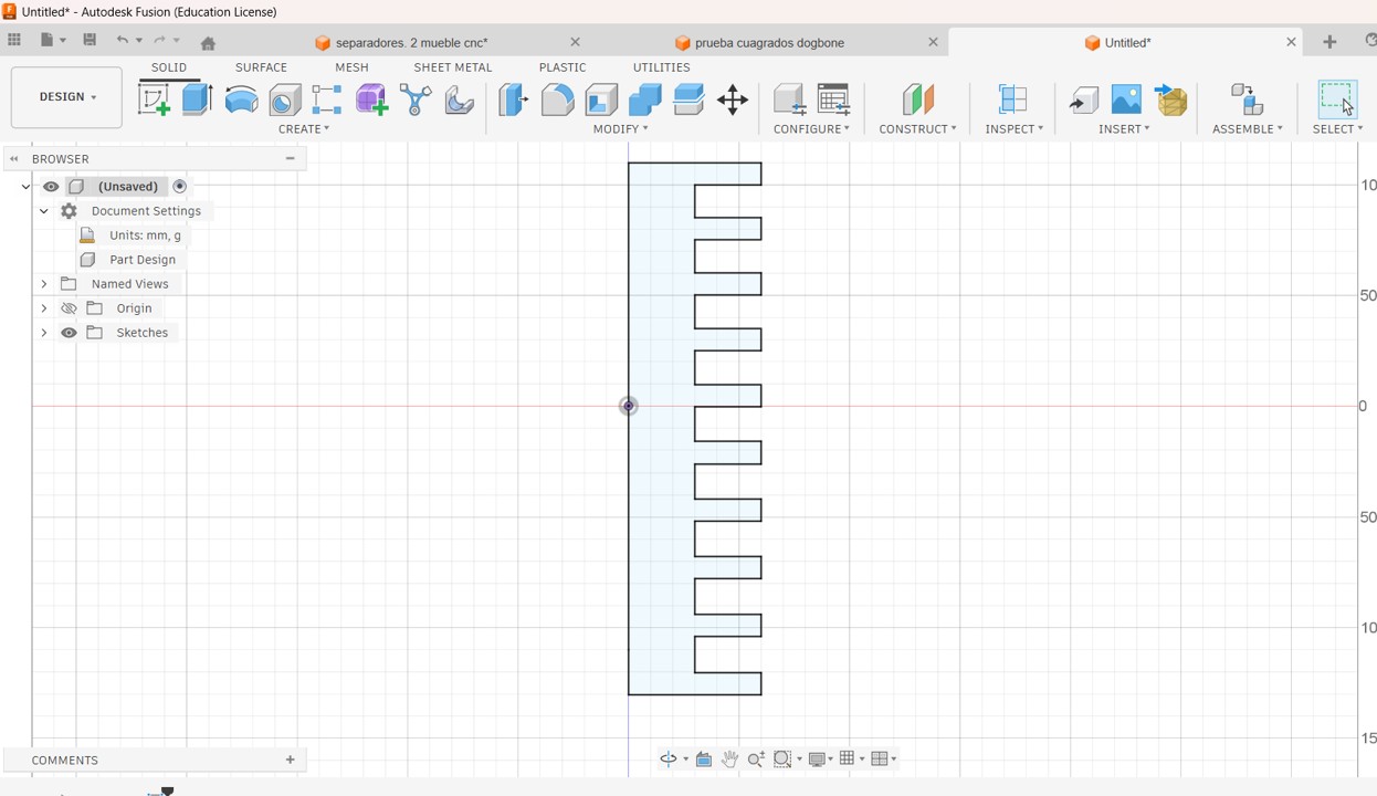
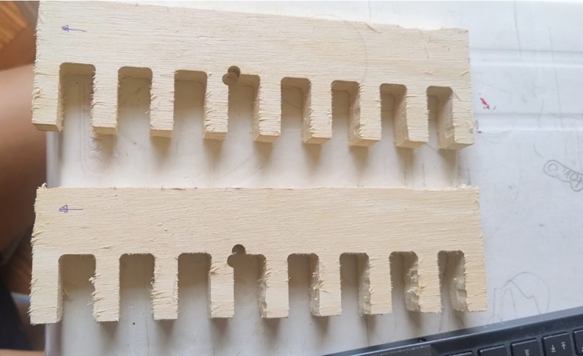
I also designed a comb test to study insertions. In this case, I designed teeth 30 mm long by 10 mm wide, leaving the slots with these sizes: (15.0, 15.2, 15.4, 15.6, 15.8, 16.0, 16.2 and 16.4).
Img 14
Img 15
Img 16
CNC routing cutting tests
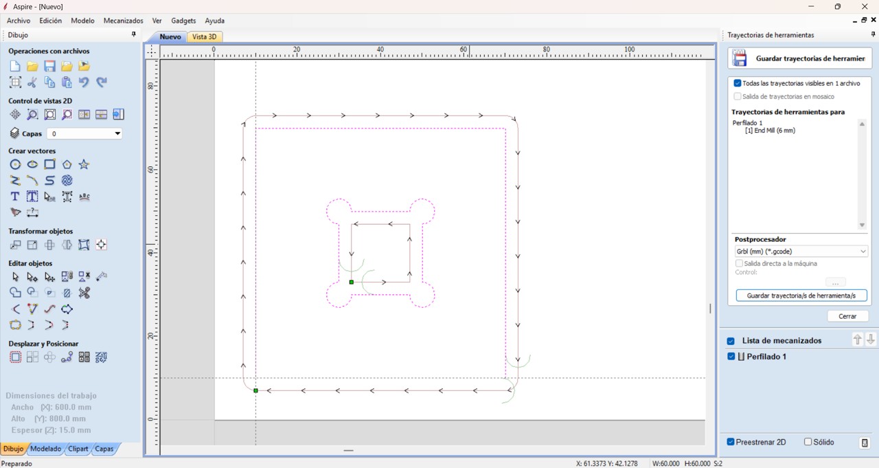
To create the G-code, I used the Aspire program. At this stage, the following are defined: material size, cutting tools, cut depth, feed speeds, and toolpaths.
Finally, the software generates the G-code file, which contains the instructions that the CNC machine executes.
For this activity, I used slot joints and dogbones. Slot joints are a technique that allows pieces to be joined easily and efficiently, guaranteeing precise alignment. On the other hand, dogbones are small circular extensions that are added to the internal corners of a design when machining with a CNC milling machine. Their main function is to compensate for the diameter of the cutting tool, since the milling bits are round and cannot generate perfectly straight 90° internal corners.
By adding a dogbone at the internal corners, a small additional space is created that allows the pieces to fit correctly during assembly, especially in slot or press-fit joints used in furniture, structures, or digital fabrication prototypes.
PROBLEMS
When I had my designs complete, I exported them in DXF format, then took them to Aspire to obtain the G-code. But here I had problems because, in the case of the dogbones, although they were in my diagram on the sheet and also in the Aspire configuration, at the time of cutting only two were clearly visible. Although I repeated and adjusted the settings, the same thing happened.
Img 17
Img 18
The same thing happened to me with the comb test. Although in my design there was no dogbone in the center, at the time of cutting two circles appeared that were not in my design. I think it is the work start marking, but I still need to verify it.
Img 19
To determine the appropriate tolerance between the parts, a calibration test was performed using a comb test with different slot sizes. The material used has a nominal thickness of 15 mm; however, during the tests it was observed that the best fit was obtained with slots of 15.8 mm and 16.2 mm. This indicates that an additional tolerance is required with respect to the material thickness in order to achieve an adequate assembly.
Clearance calculation
For the 15.8 mm slot
15.8 – 15 = 0.8 mm
For the 16.2 mm slot
16.2 – 15 = 1.2 mm
This means that the system needs an approximate tolerance between 0.8 mm and 1.2 mm to allow an adequate assembly.
These variations may be due to:
bit diameter
machine precision
machining parameters
material variations
For this reason, carrying out calibration tests is essential before manufacturing final pieces.
8. Conclusion
CNC machining makes it possible to integrate the complete process of design, programming, and digital fabrication within the Fab Lab.
During this week, the operation of the workflow was understood from the design in Fusion 360, the generation of toolpaths in Aspire, and the control of the machine through Nomad Panel.
In addition, the tolerance test made it possible to identify the appropriate assembly values for the material used, which is a fundamental step to achieve functional parts and precise assemblies in digital fabrication processes.
Since, honestly, using this equipment caused me a little fear, mostly because of the power it has, I decided to always review this checklist before starting work on the CNC.
✓
Safety verification
Status
☐
Use of safety glasses
☐
Hair tied back and no loose clothing or accessories
☐
Clean work area free of loose objects
☐
Material correctly fixed to the worktable
☐
Correct bit installed and properly tightened
☐
Inspection of the cutting tool condition
☐
G-code file loaded correctly
☐
Machine origin (X, Y, Z) configured
☐
Toolpath and cut depth verification
☐
Emergency stop button identified
☐
Correct connection between computer and CNC
☐
Constant supervision during machining
II) Individual Project
Make (design+mill+assemble) something big
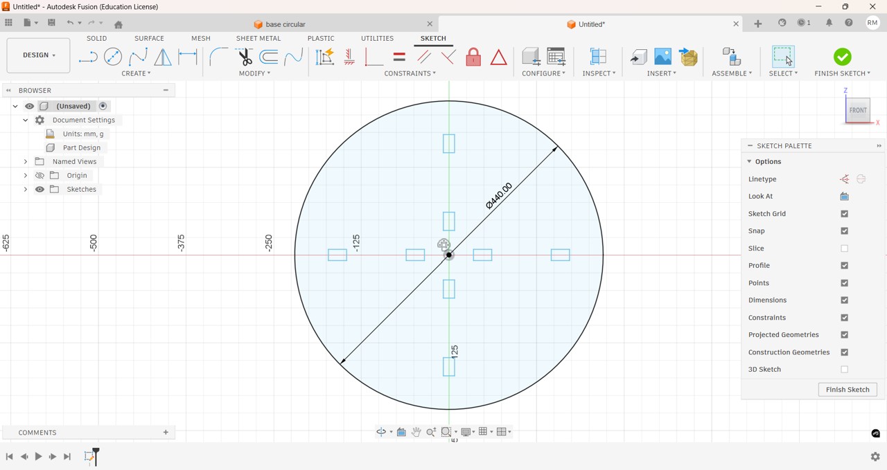
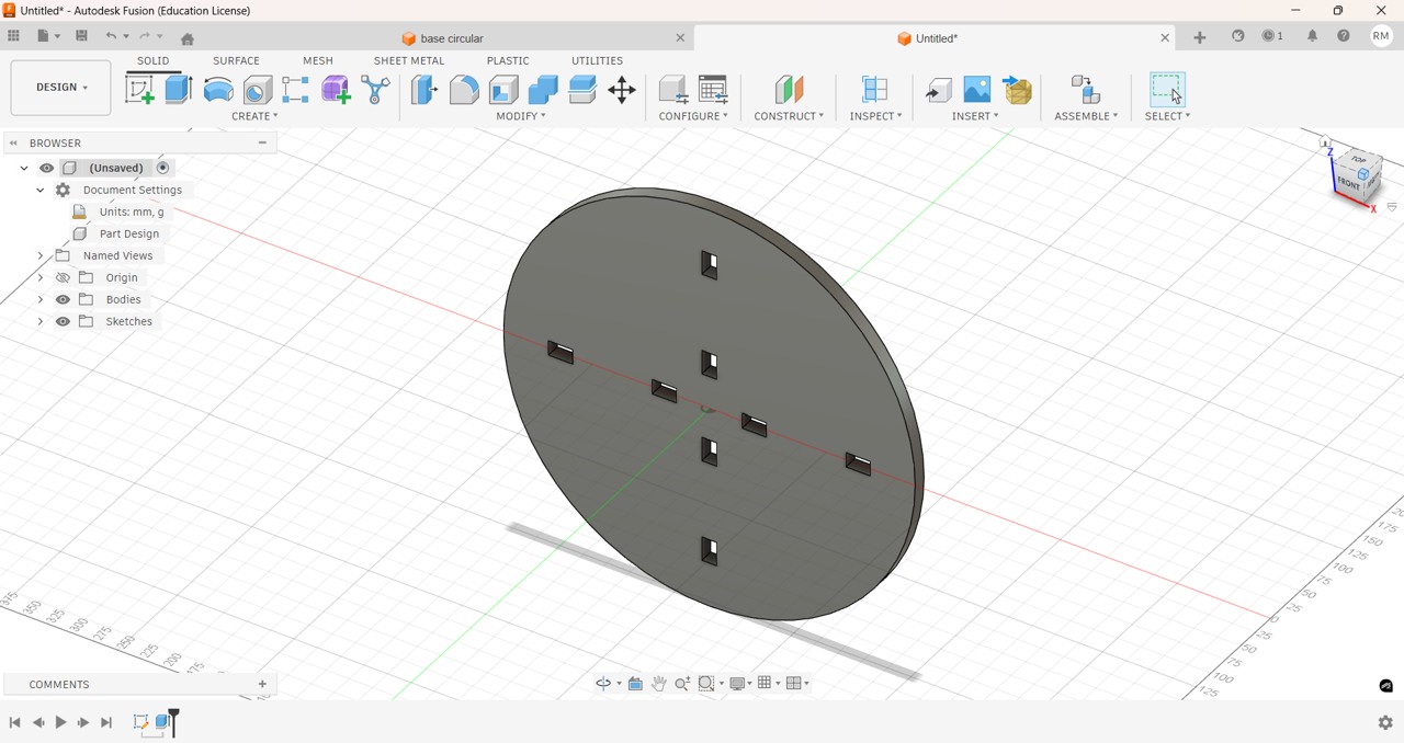
To carry out my individual project, I was reviewing several designs and I could not decide which one to make. One limitation for some designs was the size of the work area of the Fox Screw S CNC router, 75 cm long by 50 cm wide, so I opted for a puzzle-type piece of furniture to scale upwards with levels.
First, I sketched my design on paper and started sketching dimensions, base diameter, useful height, number of levels, etc.
Img 20
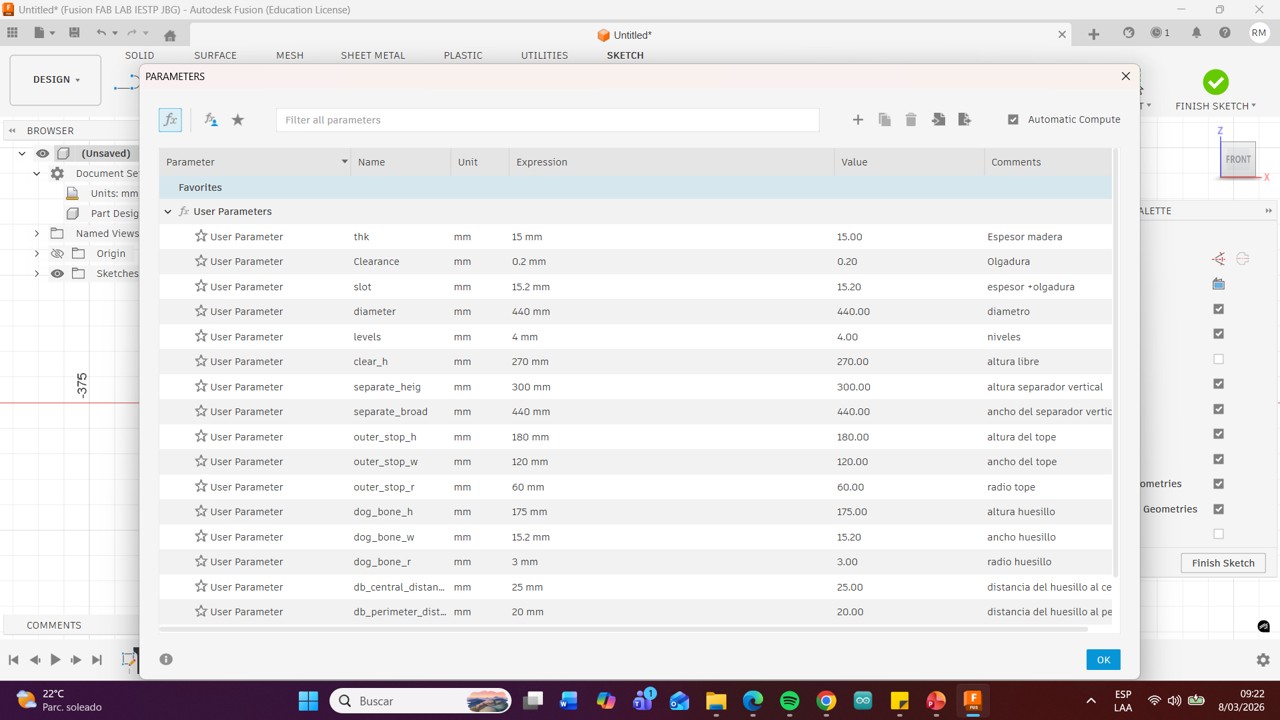
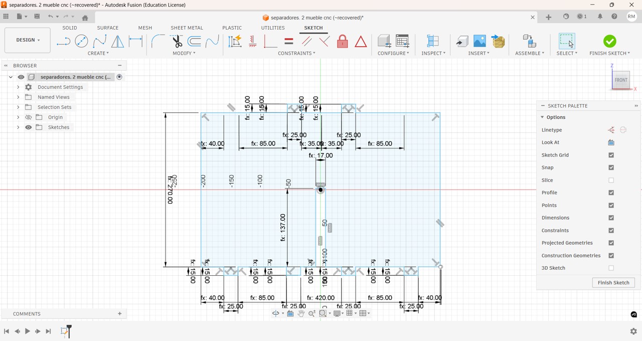
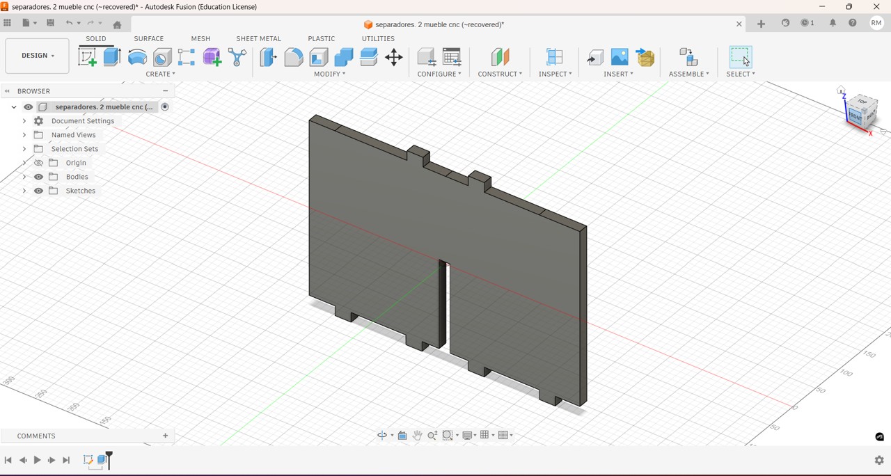
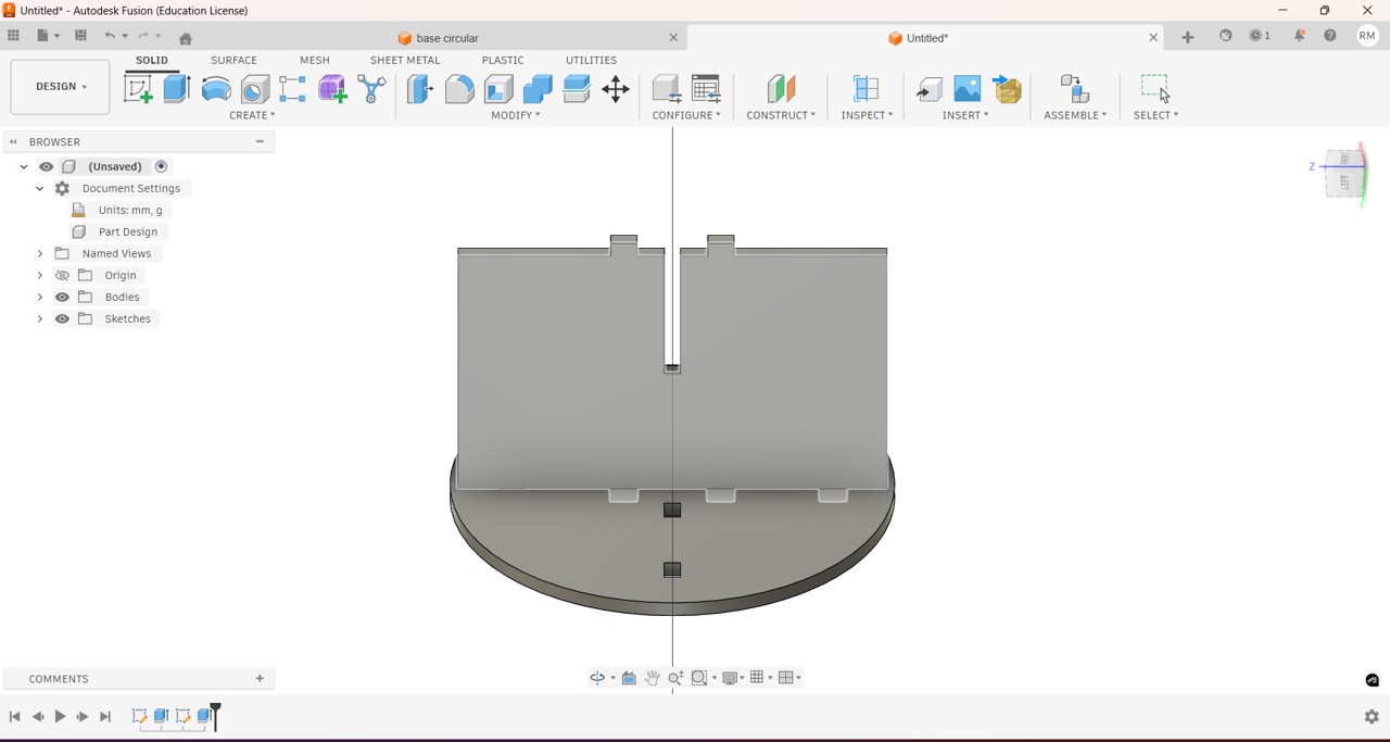
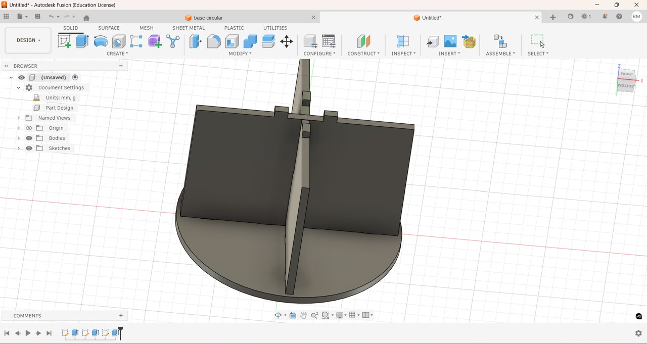
Then I made the design using Fusion 360, for this I first added the parameters to be used so that if I needed to make changes in the measurements it would be easier and faster.
Img 21
Img 22
Img 23
Img 24
Img 25
Img 26
Img 27
Img 27
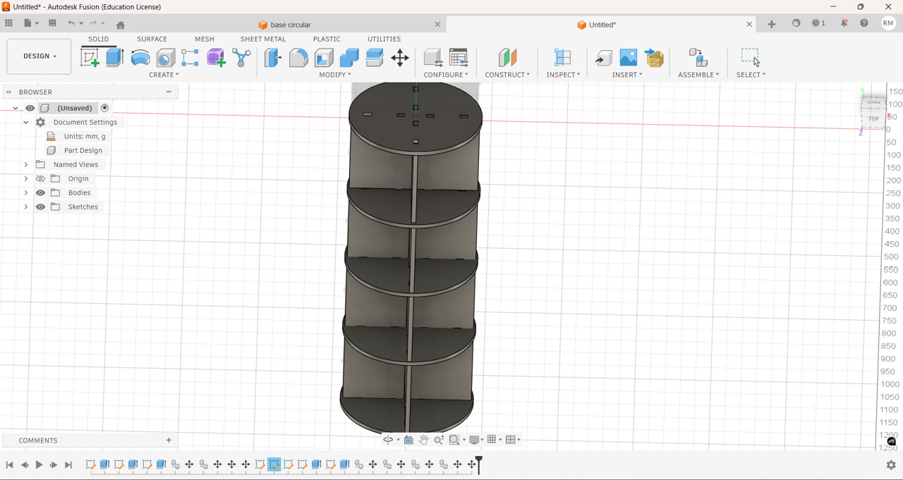
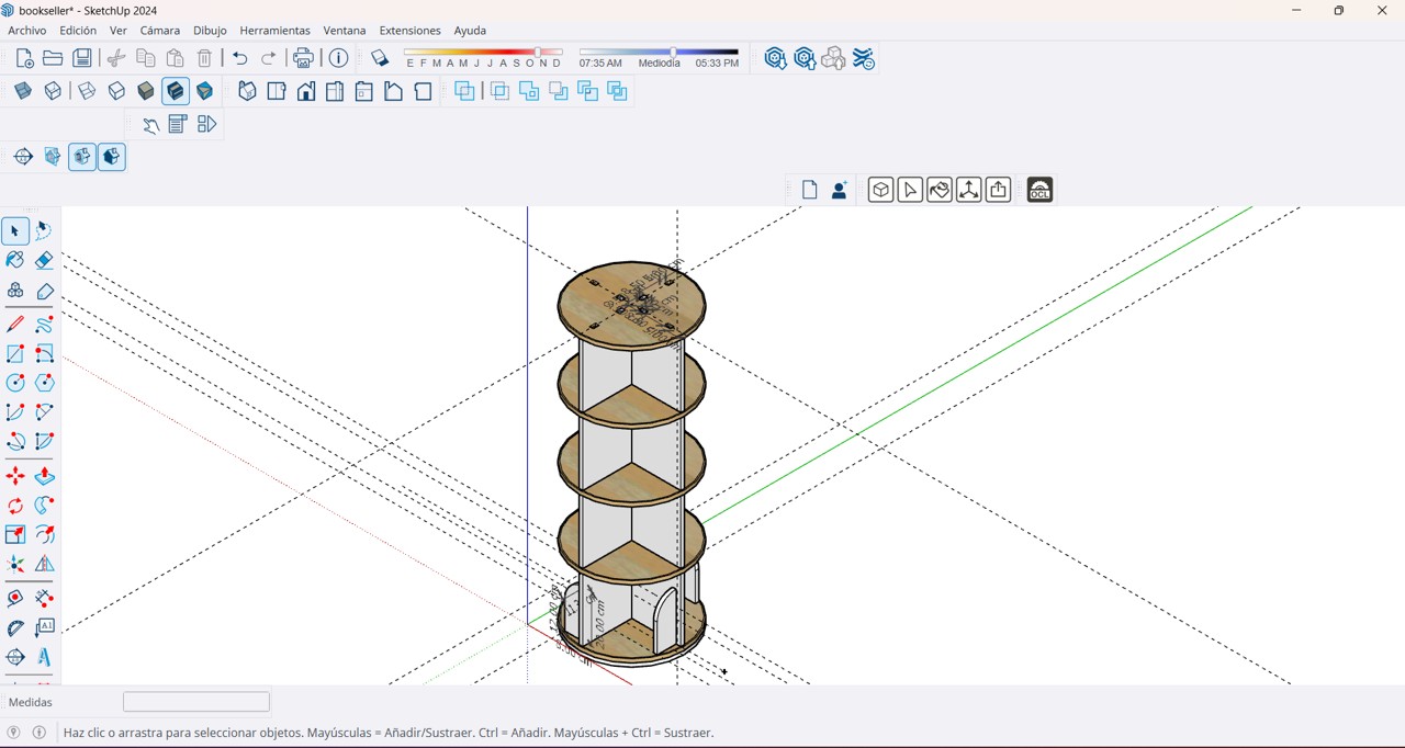
Then I had problems assembling the 3D pieces in Fusion so I decided to finish my 3D model in SketchUp, I must continue practicing in order to understand how the pieces are assembled and make them fit well, the 15 mm plywood that I purchased only allowed me to build 4 levels of my furniture, since due to the lack of gasoline in the city the costs increased a lot,
Img 28
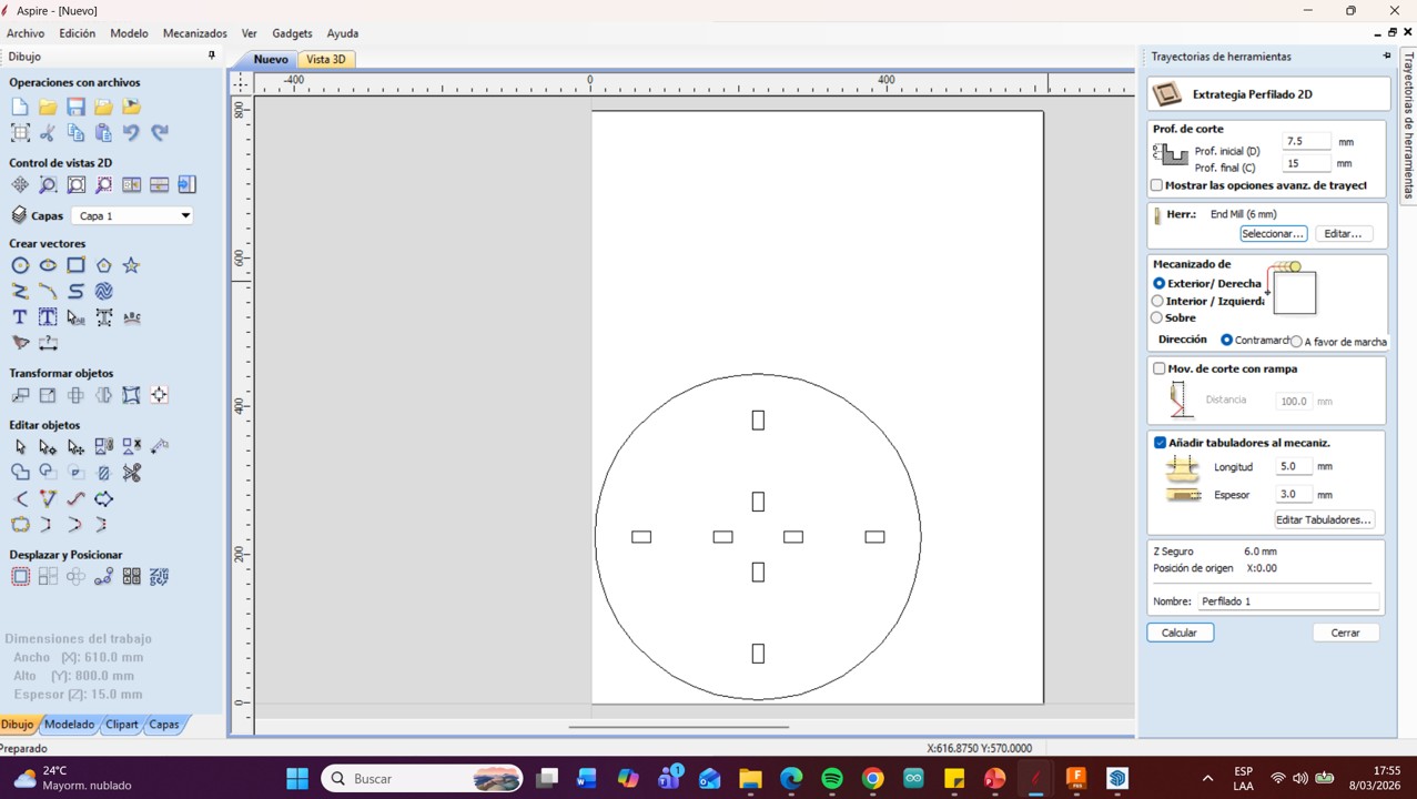
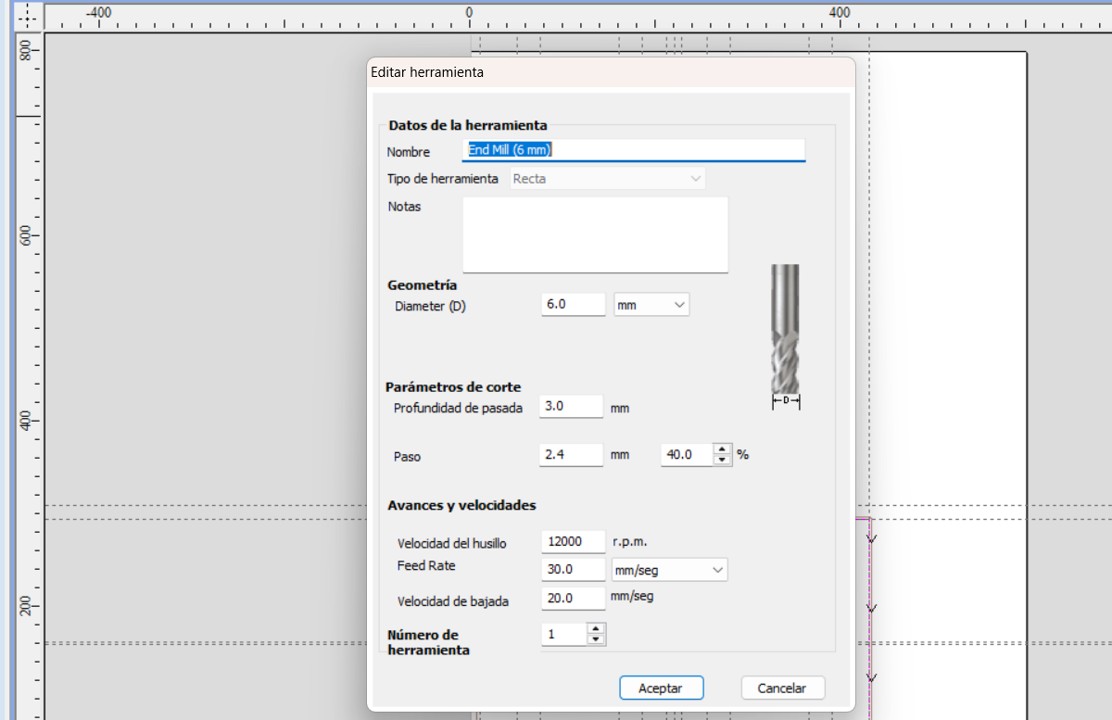
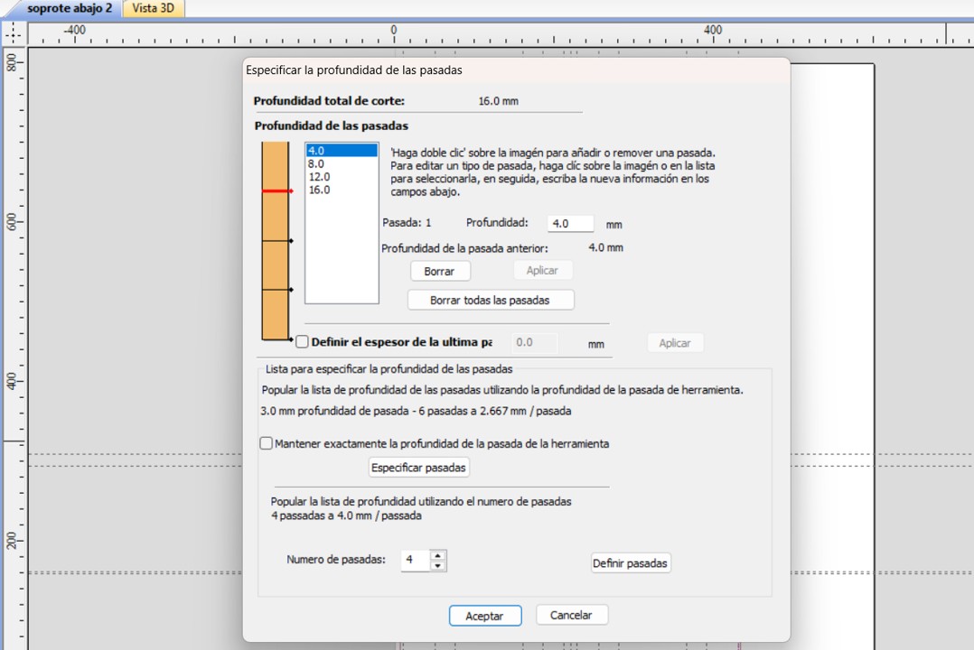
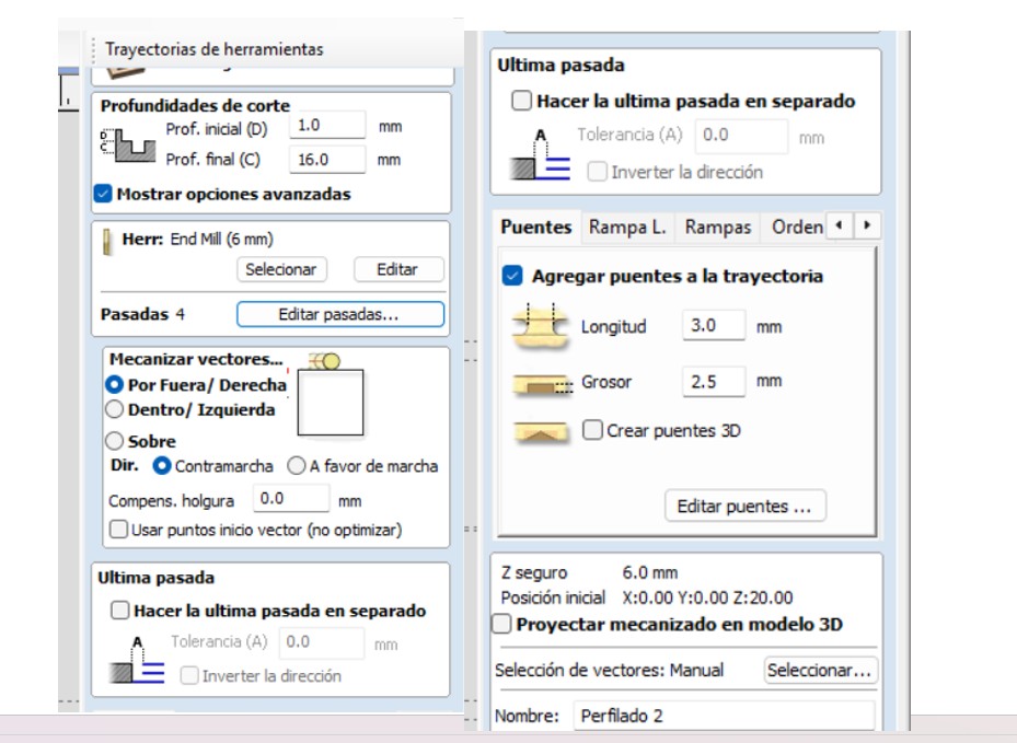
But in order to import the exact measurements I worked on the pieces in Fusion and then exported them in DXF and worked with Aspire to generate the G-code. In Aspire I had to adjust the parameters: Initial depth 1.0 mm, Final depth 16.0 mm, I changed the tool type to a 6 mm End Mill and reduced the feed rate speed from 60 mm/sec to 30 mm/sec, I modified the passes and worked with 4 passes to prevent the plywood from splintering, I placed the vector machining on the outside, I also added two tabs of 3 mm length and 2.5 mm thickness, to prevent the material from moving during cutting, in the first test I only made the cut of one piece to test the parameters.
Img 29
Img 30
Img 31
Img 32
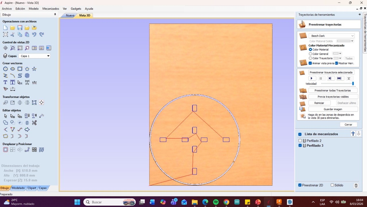
Then I calculated the work and viewed the preview, this is very important since it allows you to see if there is an extra line or point that can damage the cut of your toolpath.
Img 33
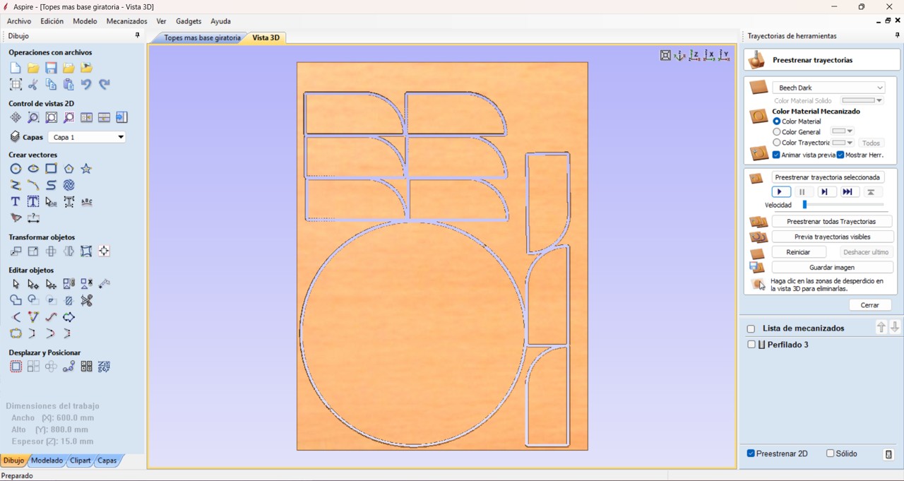
Then I sent the paths by cutting groups adjusting the material size that divides it according to the work area of the equipment.
Img 34
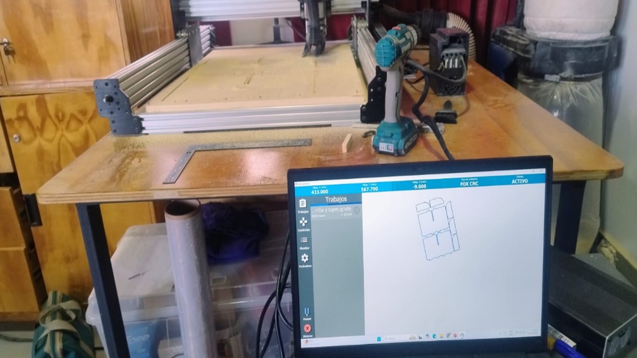
And finally I saved the post-processing in Grbl (mm) (*.gcode) and saved the toolpaths and imported this into the Nomad Panel to make the respective cuts.
Img 35
Video 1
After having all the cuts I was excited because I already wanted to assemble the furniture and see my first piece of furniture assembled with my own hands.
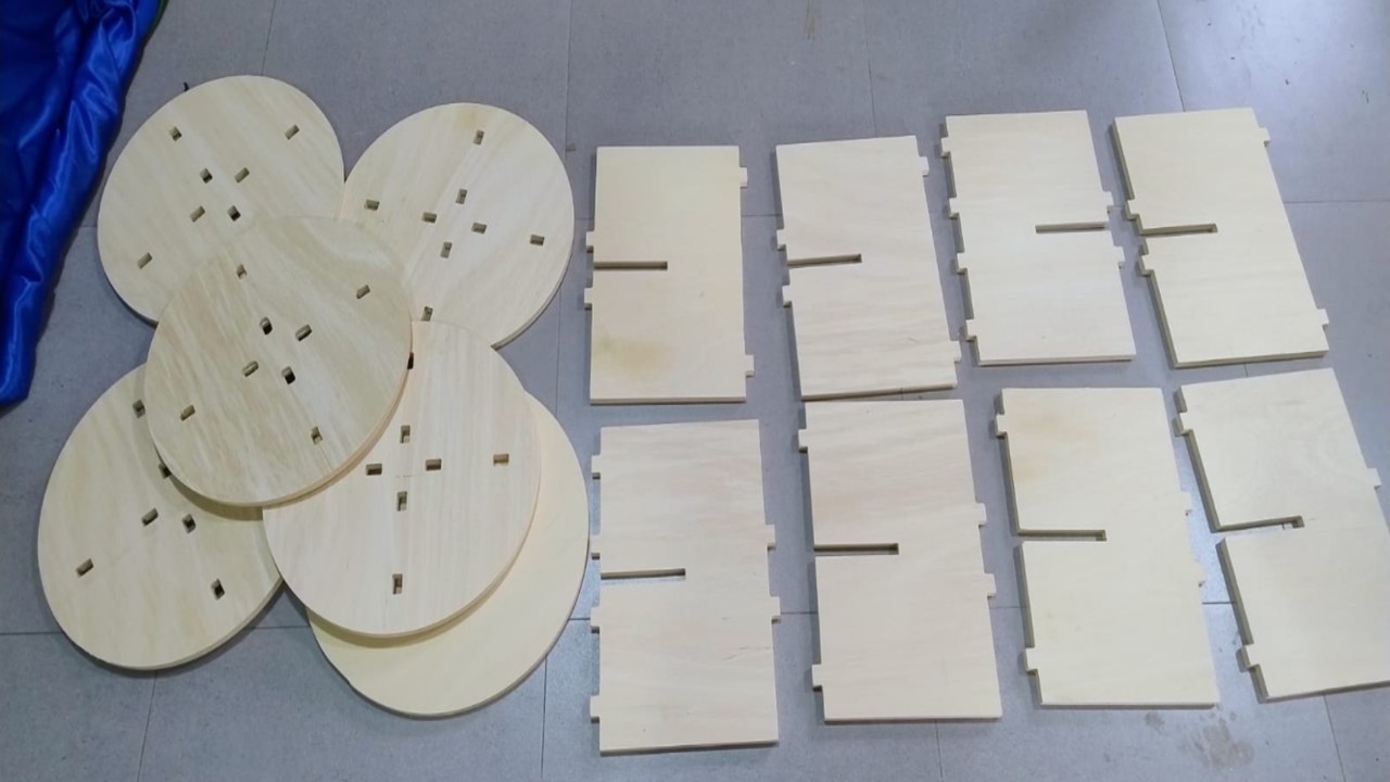
Img 36
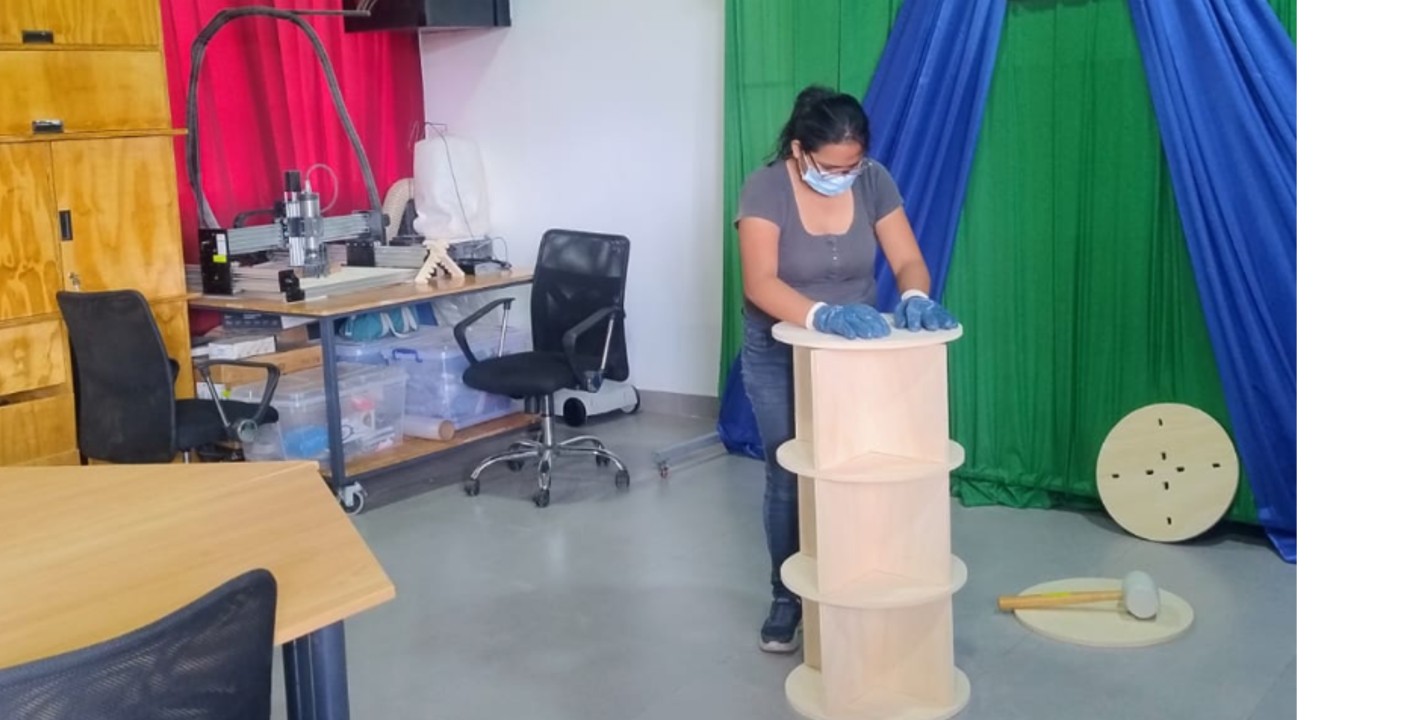
In order to assemble it first I put on gloves and a mask because there was a lot of fine dust and I had to clean it, every level that I assembled was a tremendous emotion.
Img 37
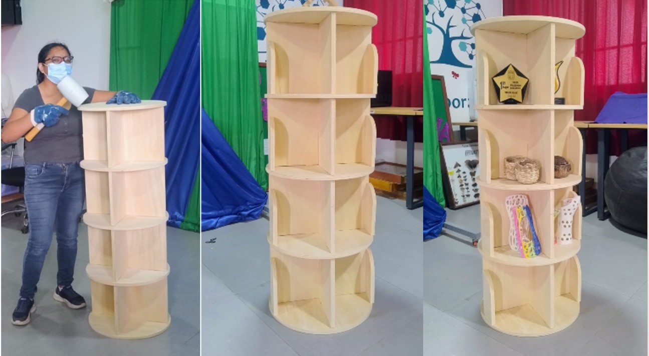
And finally furniture finished and ready to use.
Img 38
III) Conclusions and Reflections
Conclusion of the Individual Project
The individual project allowed me to experience the complete process of designing, machining, and assembling a large-scale object using CNC technology. From the initial idea to the final assembly, this work helped me understand how important it is to carefully plan dimensions according to the machine work area and the available material.
During the design stage, I learned the importance of using parametric design tools such as Fusion 360, since they allow dimensions to be modified quickly and help maintain consistency throughout the project. Although I encountered some difficulties when assembling the parts in 3D, this experience showed me that I need to continue practicing digital design and assembly strategies to achieve better precision in future projects.
The machining stage helped me better understand the importance of CNC parameters such as feed rate, cutting depth, tool diameter, and number of passes. Small adjustments in these parameters can significantly affect the quality of the cut and the condition of the material. For this reason, performing tests before executing the final cut proved to be very useful.
Finally, assembling the furniture was one of the most satisfying moments of the project because it allowed me to see how a digital design can be transformed into a real object. This experience strengthened my understanding of digital fabrication and increased my confidence in working with CNC machines.
General Reflections of the Week
This week was very important because it integrated several aspects of digital fabrication, including safety training, machine understanding, calibration tests, digital workflow, and final fabrication. It helped me understand that CNC machining is not only about cutting materials, but about understanding the entire process from design to production.
One of the most valuable lessons was the importance of safety in the Fab Lab. Working with CNC machines requires attention, preparation, and respect for safety procedures. The training session helped me become more aware of potential risks and the importance of using personal protective equipment and maintaining an organized work environment.
Another key learning point was the importance of testing and calibration. The comb test and tolerance experiments demonstrated that real material behavior may differ from theoretical dimensions, making it necessary to test before producing final pieces.
Additionally, this week allowed me to connect different software tools within a digital fabrication workflow. Using Fusion 360 for design, Aspire for toolpath generation, and Nomad Panel for machine control helped me understand how digital manufacturing systems work together.
Although at the beginning I felt a little intimidated by the CNC machine due to its power, this experience helped me gain confidence and better understand the fabrication process. Overall, this week strengthened both my technical knowledge and my practical skills in digital fabrication.
Project Files
In this section, the design and fabrication files used for this project are shared. These files include the original CAD design, the CAM toolpaths, and additional modeling files used during the development of the furniture.