I) Group Assignment
During Week 4 (Embedded Programming), we met and organized with the team, and decided to split into groups of two to complete the work. In my case, I worked with my colleague David Avila Pimentel. To divide the work, each of us focused on a different microcontroller. I documented the XIAO-ESP32-C3, and my colleague documented the XIAO-RP2040. Afterward, we met to share our findings and compare toolchains and development workflows across different microcontroller families.
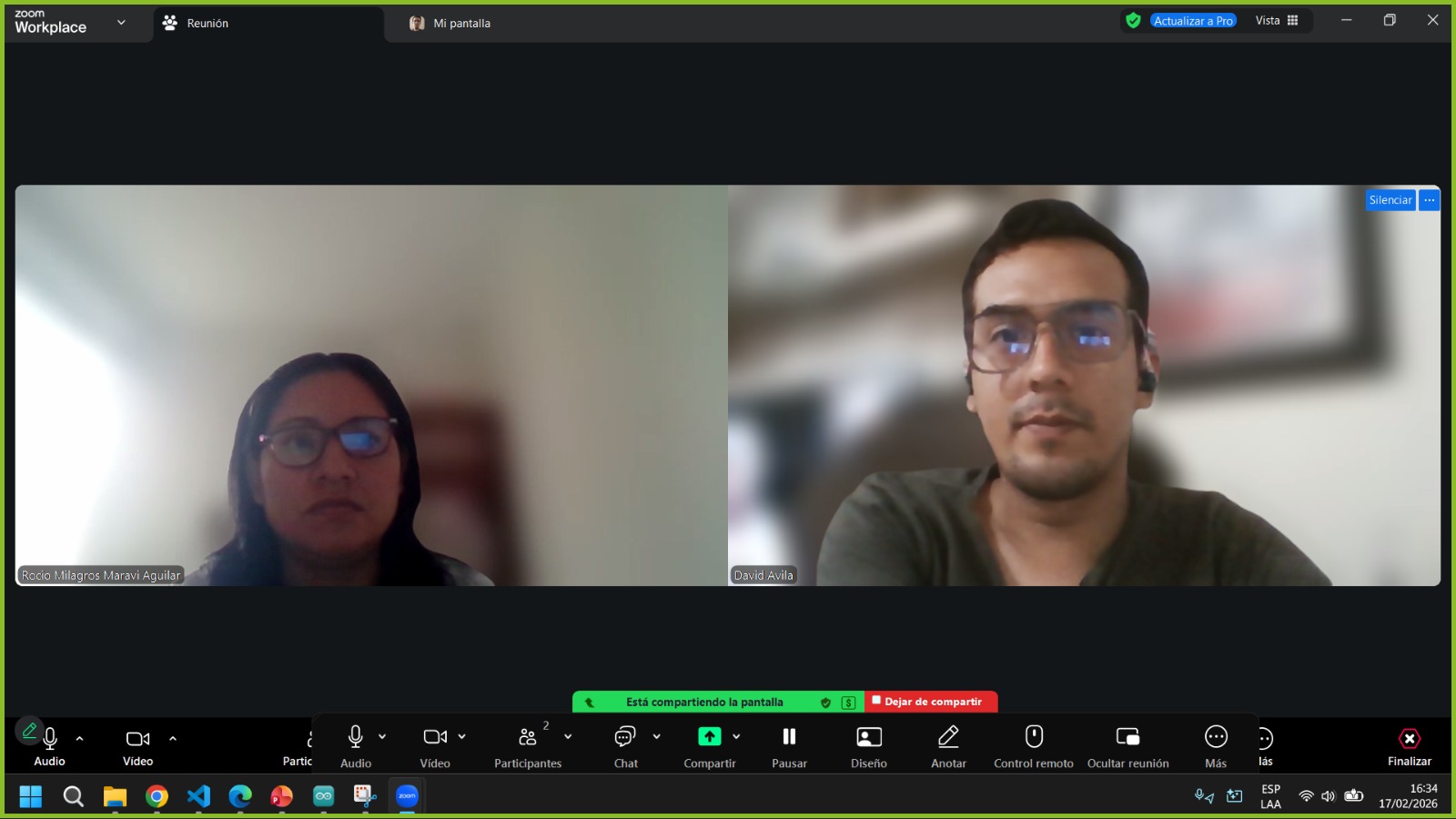
Image 1: Physical comparison of structures
What is a microcontroller?
A microcontroller (MCU) is like the "brain" of many electronic devices. Imagine it as a tiny computer built into one single chip. It's responsible for making decisions and controlling other components in real time, just like your brain tells your muscles what to do. These chips are commonly found in things like home appliances, robots, thermostats, medical equipment, or smart gadgets connected to the Internet (IoT).
Key Components of a Microcontroller (MCU)
| Component |
Description |
Function & Use Case |
| CPU |
Central Processing Unit |
The "brain" of the MCU. It processes instructions, performs calculations, and makes logical decisions. |
| Flash Memory |
ROM (Read-Only Memory) |
Non-volatile storage where the program (code) is kept. It remains saved even when the power is turned off. |
| RAM |
Random Access Memory |
Temporary workspace used for storing variables and data while the program is actively running. |
| I/O Pins |
Input/Output Pins |
Physical interfaces used to connect sensors (inputs) and actuators like LEDs or motors (outputs). |
| Timers & Interrupts |
Timing & Control |
Hardware tools used to handle events at precise intervals or to react immediately to external signals. |
| Communication |
Communication Modules |
Built-in protocols (Wi-Fi, Bluetooth, USB, UART, I2C) that allow the MCU to talk to other devices. |
Microcontrollers are programmed to follow a list of instructions. Once you load a program into it, it can perform tasks automatically, like turning on a light when it gets dark or sending data to your phone when it detects motion.
In this section, I’m presenting a head-to-head comparison between two powerhouse microcontrollers: the Seeed Studio XIAO RP2040 and the ESP32-C3. Although they share a small form factor, their design approaches are worlds apart. After a Zoom session with my teammate Rocio, we organized the following structure to demonstrate and compare their development workflows.
1. Architecture Comparison
| Feature |
Seeed Studio XIAO RP2040 |
Seeed Studio XIAO ESP32-C3 |
| Microcontroller |
Raspberry Pi RP2040 |
Espressif ESP32-C3 |
| Architecture |
Dual-core ARM Cortex-M0+ |
Single-core 32-bit RISC-V |
| Clock Speed |
133 MHz |
160 MHz |
| Connectivity |
None (Wired only) |
Wi-Fi + Bluetooth 5.0 (LE) |
| SRAM |
264 KB |
400 KB |
| Flash Memory |
2 MB |
4 MB |
| Core Strength |
PIO (Programmable I/O): Hardware-level custom protocols. |
IoT & Security: Hardware encryption and native wireless. |
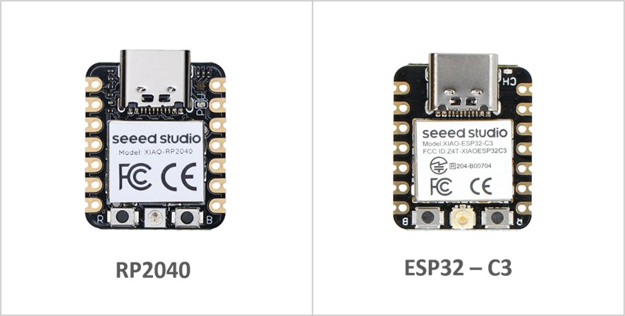
Image 2: Physical comparison of structures
2. Toolchains (Development Environment)
The toolchain is the set of tools (compiler, linker, debugger) used to turn your code into a binary the chip can understand.
| Feature |
Seeed Studio XIAO RP2040 |
Seeed Studio XIAO ESP32-C3 |
| ISA (Architecture) |
ARMv6-M (Proprietary) |
RISC-V (Open Standard) |
| Main Compiler |
arm-none-eabi-gcc |
riscv32-esp-elf-gcc |
| Official SDK |
Pico C/C++ SDK (Bare-metal) |
ESP-IDF (Built on FreeRTOS) |
| Build System |
CMake / Ninja |
CMake / Ninja (via idf.py) |
| Primary Frameworks |
Arduino Core, MicroPython, CircuitPython |
Arduino Core, ESP-IDF, MicroPython |
| Hardware Debugging |
SWD (Requires external probe) |
Built-in USB-JTAG (No probe needed) |
| Binary Format |
.uf2 (Universal Flashing Format) |
.bin (Standard ESP Binary) |
Key Points:
- The RP2040 Ecosystem is highly portable. Because it uses the ARM standard, many developers find the transition from other chips (like STM32) very easy. The UF2 bootloader is its "secret weapon" for group projects because it removes the need for special drivers to upload code.
- The ESP32-C3 Ecosystem is more specialized but powerful. It is essentially a "system-on-a-chip" designed to run a multitasking OS (FreeRTOS) by default. This makes the toolchain slightly heavier but allows for complex features like background Wi-Fi management.
3. Development Workflows
| Phase |
Seeed Studio XIAO RP2040 |
Seeed Studio XIAO ESP32-C3 |
| Boot Mode |
Physical "BOOT" button + Plug USB. |
Auto-reset via DTR/RTS (usually). |
| Upload Method |
Drag & Drop (UF2): Mounts as a mass storage drive. |
Serial Flashing: Over a COM port (UART/USB-CDC). |
| File Handling |
Ideal for CircuitPython (edit files directly on the drive). |
Compiled binaries (.bin) managed by esptool. |
| I/O Control |
PIO State Machines: High-speed, independent hardware logic. |
Software-defined: Standard GPIO/Peripherals. |
| Memory Mgmt. |
Single flat memory space (Simple). |
Partition Tables: Separate NVS, OTA, and App data. |
| Remote Updates |
Limited/Complex (Needs external hardware). |
Native OTA (Over-the-Air): Update via Wi-Fi. |
Workflow Analysis:
- The RP2040 Workflow is superior for rapid prototyping and educational settings. The fact that it behaves like a USB flash drive removes the "driver hell" often associated with microcontrollers. If your group wants to show a quick demo of changing code on the fly, this is the better choice.
- The ESP32-C3 Workflow is better for IoT Deployment. Its workflow assumes the device might not be plugged into a computer forever. The ability to manage memory partitions and perform OTA updates makes it the professional choice for connected devices.
4. Example Program: LED blinking
Code used:
int led = 10;   // Define the LED pin

void setup() {
  pinMode(led, OUTPUT); // Configure the pin as output
}

void loop() {
  digitalWrite(led, HIGH); // Turn on the LED
  delay(1000);             // Wait 1000 ms
  digitalWrite(led, LOW);  // Turn off the LED
  delay(1000);             // Wait 1000 ms
}
Video 1 – Programming for LED lighting with the XIAO ESP32-C3
5. Group Conclusions
- Architecture & Power: While both share a compact footprint, the RP2040 offers a dual-core ARM Cortex-M0+ focused on high-speed hardware manipulation through its unique PIO (Programmable I/O). The ESP32-C3 uses a single-core RISC-V architecture designed specifically for the IoT era, integrating native Wi-Fi and Bluetooth.
- Connectivity & Scope: The ESP32-C3 is the clear winner for wireless projects, cloud integration, and remote monitoring. The RP2040 is better suited for standalone applications, high-performance local control, or scenarios where emulating specific hardware protocols is required.
- Toolchain & Debugging: The RP2040 follows traditional ARM standards, making it highly portable and easy to use with common compilers. However, the ESP32-C3 provides a more modern debugging experience with its built-in USB-JTAG, allowing for real-time code inspection without additional hardware.
- Development Workflow: The RP2040 excels in ease of use for beginners and rapid prototyping thanks to its "drag and drop" UF2 bootloader. Conversely, the ESP32-C3 offers a more robust industrial workflow, supporting multitasking via FreeRTOS and professional features like Over-the-Air (OTA) updates.
- Ecosystem & Community: The RP2040 benefits from the massive Raspberry Pi community and is the premier choice for Python-based embedded development. The ESP32-C3 leverages the mature Espressif ecosystem, which is the industry standard for low-cost, secure IoT deployment.
II) Individual Assignment
Browse through the datasheet for a microcontroller.
Write and test a program for an embedded system using a microcontroller to interact (with local input &/or output devices) and communicate (with remote wired or wireless connections).
1. General Description: XIAO-ESP32-C3
Seeed Studio XIAO ESP32C3 is an IoT mini development board based on the Espressif ESP32-C3 WiFi/Bluetooth dual-mode chip, featuring a 32-bit RISC-V CPU that delivers powerful computing performance with its efficient architecture. It has excellent radio frequency performance, supporting IEEE 802.11 b/g/n WiFi, and Bluetooth 5 (BLE) protocols. This board comes included with an external antenna to increase the signal strength for your wireless applications. It also has a small and exquisite form-factor combined with a single-sided surface-mountable design. It is equipped with rich interfaces and has 11 digital I/O that can be used as PWM pins and 4 analog I/O that can be used as ADC pins. It supports four serial interfaces such as UART, I2C and SPI.
Hardware Specifications
| Specification |
Description |
| Processor | 32-bit RISC-V single-core processor up to 160 MHz |
| Connectivity | Wi-Fi 2.4 GHz + Bluetooth 5 BLE |
| Memory | 400 KB SRAM + 4 MB Flash |
| Interfaces | UART, I2C, SPI, 11 GPIO PWM, 4 ADC |
| Dimensions | 21 x 17.8 mm |
| Power | 5V VIN or 3.7V BAT |
| Temperature | -40°C to 85°C |
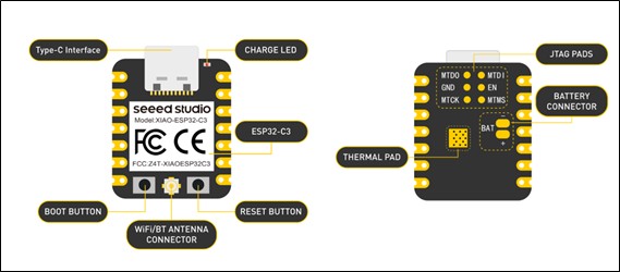
Image 3
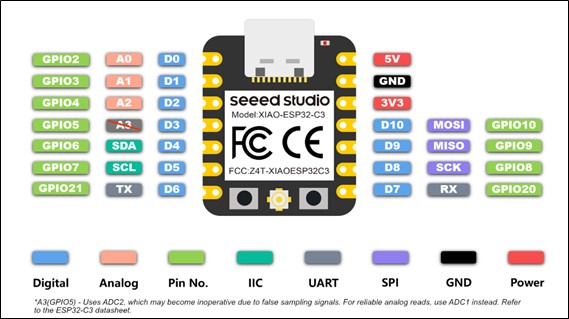
Image 4
3. Software & Workflow
- IDE/Development Environment: ESP-IDF (official), Arduino IDE, or PlatformIO.
- Compiler GCC (for traditional ESP32), riscv32-espidf-gnu-toolchain (for ESP32-C3).
- Build Tools: CMake and Make (ESP-IDF), PlatformIO (automatic).
- Debugging and Programming: OpenOCD or Segger J-Link, esptool.py.
Set up the development environment, write the code using the appropriate libraries, build the project, upload firmware using USB and BOOTSEL mode, debug if necessary, and test the results.
4. Testing for ESP32-C3
We started with acquiring the microcontroller, which was a real headache because where I live I could only find Arduino boards, so finding ESP32-C3 was a challenge, especially for me because I know almost nothing about electronics, so this week was truly a big challenge for me. When I finally had my microcontroller in my hands, I realized it came without headers, so to facilitate testing I had to learn soldering, making sure there was no contact between pins. Then I proceeded to download Arduino.
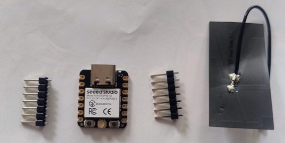
Image 5: XIAO ESP32-C3, chosen microcontroller.
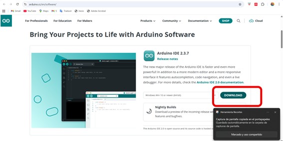
Image 6: Downloading Arduino IDE 2.3.7
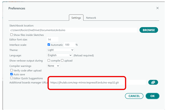
Image 7
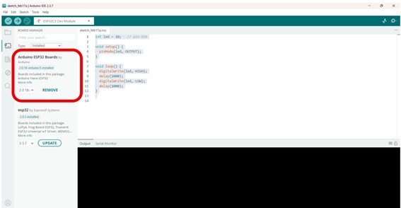
Image 8
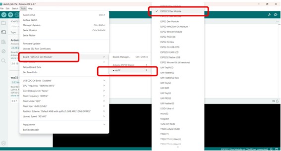
Image 9
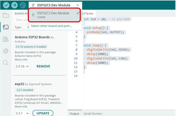
Image 10
Serial Communication Test
For my individual assignment, I programmed my ESP32-C3 microcontroller to communicate with the computer using the Serial Monitor. The board successfully printed “Hello, Hello Fab Academy” messages repeatedly, demonstrating serial communication between the microcontroller and the PC.
void setup() {
  Serial.begin(115200);     // start serial communication
}

void loop() {
   Serial.println("Hello, Hello Fab Academy!");
   delay(2000);   // repeat every 2 seconds
}
Image 11
Video 2 – Serial communication test with the XIAO ESP32-C3
5. Interacting with my devices
5.1. Simulation using Wokwi
Before assembling the physical circuit, I used the Wokwi online simulator to test my design virtually.
Wokwi allowed me to simulate the XIAO ESP32-C3 microcontroller together with the HC-SR04 ultrasonic sensor and an active buzzer. This step was very important because it helped me understand the wiring, verify the logic of the code, and detect possible mistakes before working with real electronic components.
Through simulation, I could confirm that the sensor correctly measured distance and that the buzzer activated when the object was closer than 20 cm. Using Wokwi reduced errors, saved time, and gave me confidence before moving to the real hardware implementation.
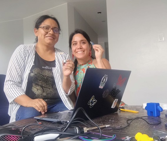
Image 12: Meeting with instructor Evelyn Cuadrado, who helped me a lot to clarify big and small doubts and provided materials.
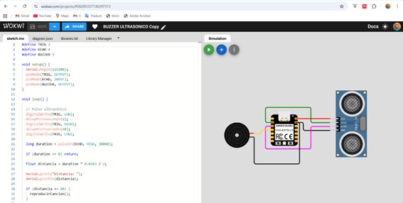
Image 13: Simulation in Wokwi
Code WOKWI
#define TRIG 3
#define ECHO 4
#define BUZZER 5

void setup() {
  Serial.begin(115200);
  pinMode(TRIG, OUTPUT);
  pinMode(ECHO, INPUT);
  pinMode(BUZZER, OUTPUT);
}

void loop() {

  // Ultrasonic pulse
  digitalWrite(TRIG, LOW);
  delayMicroseconds(2);
  digitalWrite(TRIG, HIGH);
  delayMicroseconds(10);
  digitalWrite(TRIG, LOW);

  long duration = pulseIn(ECHO, HIGH, 30000);

  if (duration == 0) return;

  float distancia = duration * 0.0343 / 2;

  Serial.print("Distance: ");
  Serial.println(distancia);

  if (distancia <= 20) {
    reproducirCancion();
  }

  delay(200);
}

void reproducirCancion() {

  tone(BUZZER, 262, 400);  // C
  delay(450);

  tone(BUZZER, 294, 400);  // D
  delay(450);

  tone(BUZZER, 330, 600);  // E
  delay(650);

  tone(BUZZER, 294, 400);
  delay(450);

  tone(BUZZER, 262, 800);
  delay(850);

  noTone(BUZZER);
}
Video 3: Simulation in Wokwi
5.2. Step-by-Step Test (Physical Implementation)
Step 1 – Preparing the Components
I gathered all the required components:
- XIAO ESP32-C3 microcontroller
- HC-SR04 ultrasonic sensor
- Active buzzer
- Breadboard
- Jumper wires
Step 2 – Wiring the Circuit
I connected the components as follows:
| HC-SR04 |
XIAO ESP32-C3 |
| VCC | 5V |
| GND | GND |
| TRIG | D3 → GPIO5 |
| ECHO | D4 → GPIO6 (with voltage divider) |
| Active Buzzer |
XIAO |
| + | D5 → GPIO7 |
| – | GND |
This step helped me understand the importance of common ground and safe voltage levels when working with sensors.
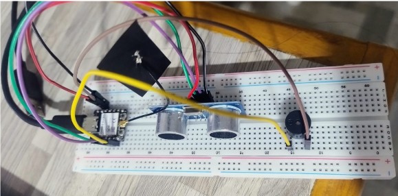
Image 14: Connections
Step 3 – Uploading the Code
I opened Arduino IDE, selected the board XIAO ESP32-C3, and uploaded the program that reads the ultrasonic sensor and activates the buzzer when distance ≤ 20 cm.
Use Code
#define TRIG 5     // D3 = GPIO5
#define ECHO 6     // D4 = GPIO6
#define BUZZER 7   // D5 = GPIO7

void setup() {
  Serial.begin(115200);
  pinMode(TRIG, OUTPUT);
  pinMode(ECHO, INPUT);
  pinMode(BUZZER, OUTPUT);
}

void loop() {

  // Ultrasonic pulse
  digitalWrite(TRIG, LOW);
  delayMicroseconds(2);
  digitalWrite(TRIG, HIGH);
  delayMicroseconds(10);
  digitalWrite(TRIG, LOW);

  long duration = pulseIn(ECHO, HIGH, 30000);

  if (duration == 0) return;

  float distancia = duration * 0.0343 / 2;

  Serial.print("Distance: ");
  Serial.println(distancia);

  if (distancia <= 20) {
    digitalWrite(BUZZER, HIGH);   // sound ON
  } else {
    digitalWrite(BUZZER, LOW);    // sound OFF
  }

  delay(200);
}
Step 4 – Testing with Serial Monitor
I opened the Serial Monitor at 115200 baud rate and verified that the sensor printed distance values correctly. This confirmed that communication between the microcontroller and the computer was working.
Step 5 – Final Test
When I moved my hand close to the sensor, the buzzer sounded as expected. This confirmed that:
- The wiring was correct
- The program worked correctly
- The simulation matched real results
Video 4: Testing
III) Reflections
What I Learned
- Simulation tools like Wokwi are very useful before real testing.
- Understanding pin connections is essential in electronics.
- Debugging step-by-step makes complex projects easier.
- Testing both virtually and physically increases confidence in the final design.
6. Reflections
During this week of Embedded Programming, I experienced one of the biggest learning challenges of Fab Academy. At the beginning, electronics felt intimidating because I had no previous experience with microcontrollers, sensors, or programming embedded systems. However, step by step, I discovered that understanding electronics is very similar to learning a new language: at first it seems confusing, but with practice and patience everything starts to make sense.
Working with the XIAO ESP32-C3 helped me understand how software and hardware interact in real time. Seeing a simple message like “Hello Fab Academy” appear in the Serial Monitor felt very exciting because it showed that the microcontroller and the computer were communicating correctly. Later, integrating sensors like the HC-SR04 and actuators like the buzzer allowed me to see how digital fabrication projects become intelligent systems.
Simulation with tools like Wokwi also taught me the importance of testing before building. It reduced mistakes and helped me visualize the connections more clearly. Another important lesson was learning to solder pins and troubleshoot connection problems, which gave me confidence working with physical electronics.
This week showed me that electronics is not something to fear, but something to explore with curiosity. Even small successes, like making a LED blink or a buzzer sound, are important steps toward building complex systems for my final project.
Recommendations
- Start simple. Begin with basic examples like blinking LEDs or Serial Monitor messages before connecting sensors or complex modules.
- Read datasheets carefully. Even if they seem difficult, they contain essential information about voltage, pins, and communication protocols.
- Use simulation tools. Programs like Wokwi help test ideas safely before working with real components.
- Check wiring twice. Most errors in electronics come from incorrect connections or missing ground.
- Document everything. Taking photos, notes, and screenshots makes debugging easier and improves learning.
- Ask for help early. Working with classmates or instructors saves time and helps understand concepts faster.
- Be patient. Electronics rarely works perfectly on the first try, and debugging is part of the learning process.
- Practice every day. Even 20 minutes of practice with Arduino or microcontrollers helps build confidence quickly.
Final Thought
This week transformed my perception of electronics. What once seemed difficult now feels like an exciting tool that will allow me to add intelligence, automation, and sensing capabilities to my final Fab Academy project. I am still learning, but now I feel more confident and motivated to continue exploring embedded programming.