I) Group Assignment
Reflection on Laser Cutter Characterization and Group Work
Coordination Meetings
The group experience during the Computer-Controlled Cutting week was
very enriching, both technically and personally. First, we held virtual
meetings with members of the FAB LAB Peru Node to coordinate the group
assignment and organize our time for the face-to-face session.
I was very excited because I live in Madre de Dios and I had not met
most of my classmates before. This made the experience even more special,
because I was finally going to meet them and work together in person.
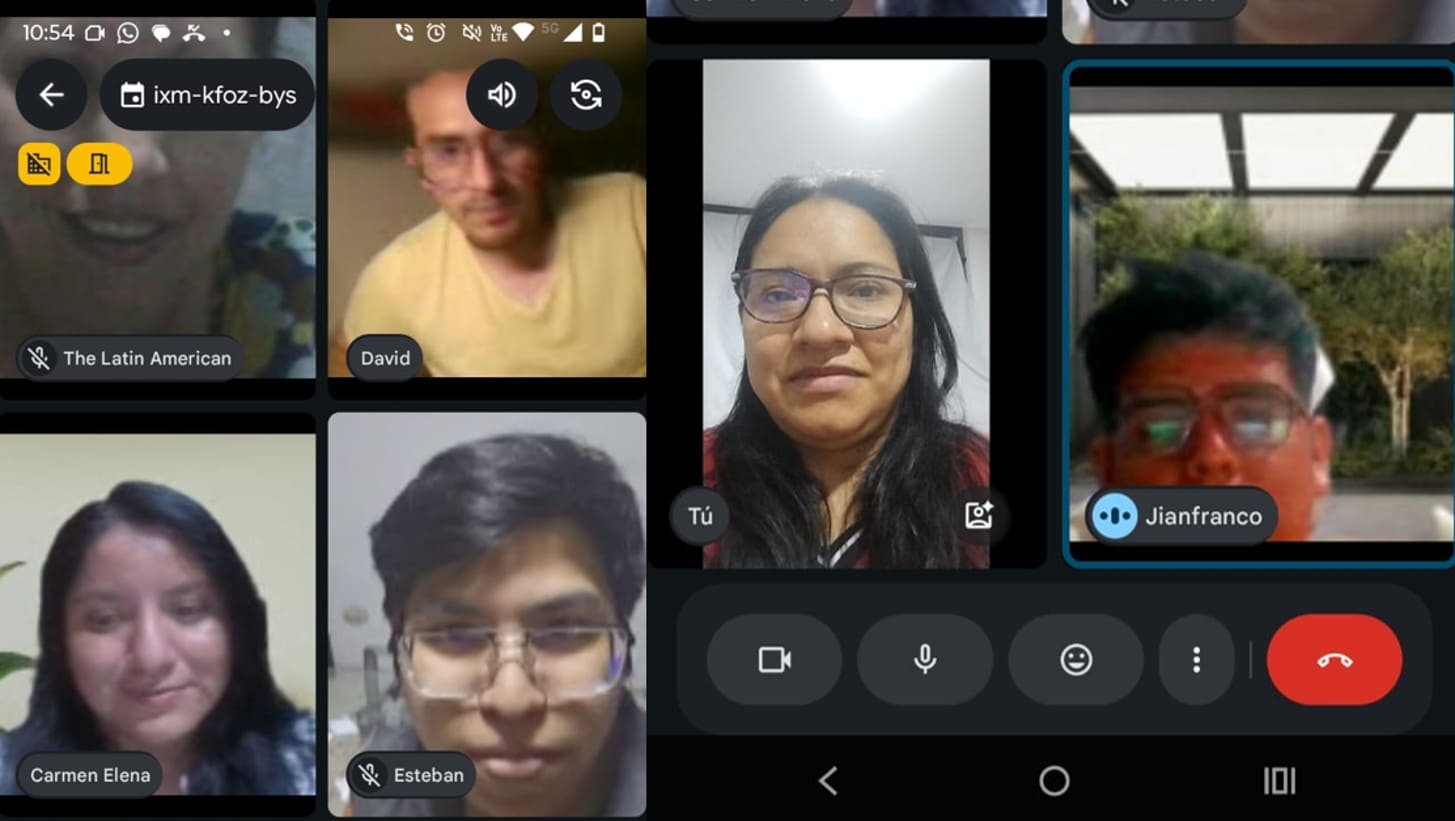
Image 1. Virtual coordination meetings.
Getting to Know Each Other
On February 6th, I finally met Jianfranco, Esteban, Carmen, and I also
met Grace again after a long time. The group meeting took place at
FAB LAB UNI, the first Fab Lab in South America, installed between
2010 and 2011 and inaugurated during the FAB7 international conference.
Working in this pioneering digital fabrication space gave a very special
historical and symbolic value to the practice. It also reinforced the
importance of the learning process we were developing during this week.
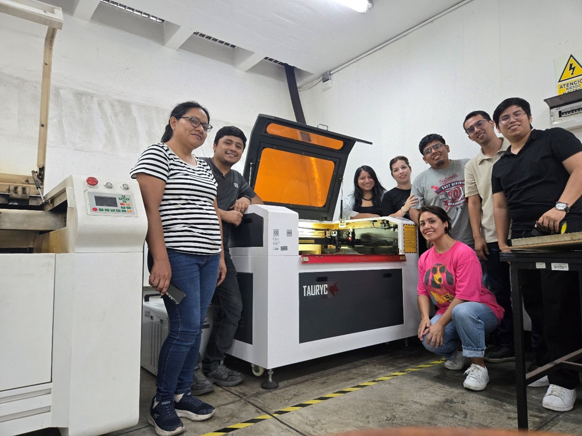
Image 2. A very fun and enthusiastic group gathered from different
parts of Peru, including Madre de Dios, Satipo, and Lima.
Safety Comes First
Before starting the tests, we received complete safety training. This
allowed me to understand that using a laser cutter is not only a matter
of design, but also a matter of responsibility.
We learned about the importance of using gloves to avoid stains or
contamination of the material, safety glasses, a mask, and hearing
protection, especially because of the loud noise produced by the air
extractor.
We were also reminded that the machine must never operate without
supervision, since the risk of fire or technical failure is real if the
process is not constantly monitored.
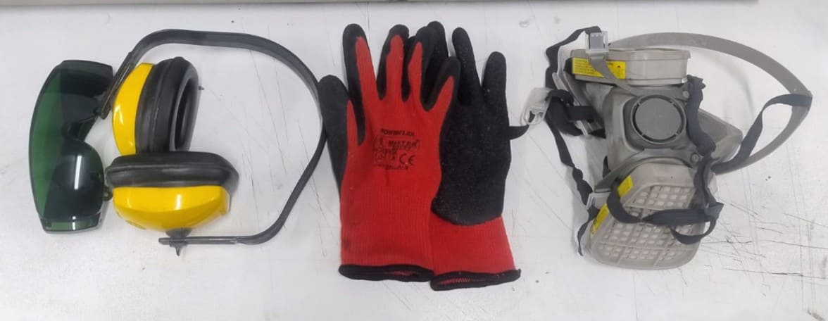
Image 3. Safety equipment, very necessary for laser cutting work.
Understanding the Laser Cutting Machine
During the technical explanation, we learned about the general operation
of the CO₂ laser cutter. We understood that the system works with a
laser tube, which requires a chiller to maintain a suitable temperature
and prevent damage.
We also learned that the machine uses a blower that directs air through
the nozzle to clean the cutting area and improve the quality of the work.
Correct mirror alignment and calibration are essential to ensure that
the laser beam reaches the material with precision and uniform power.
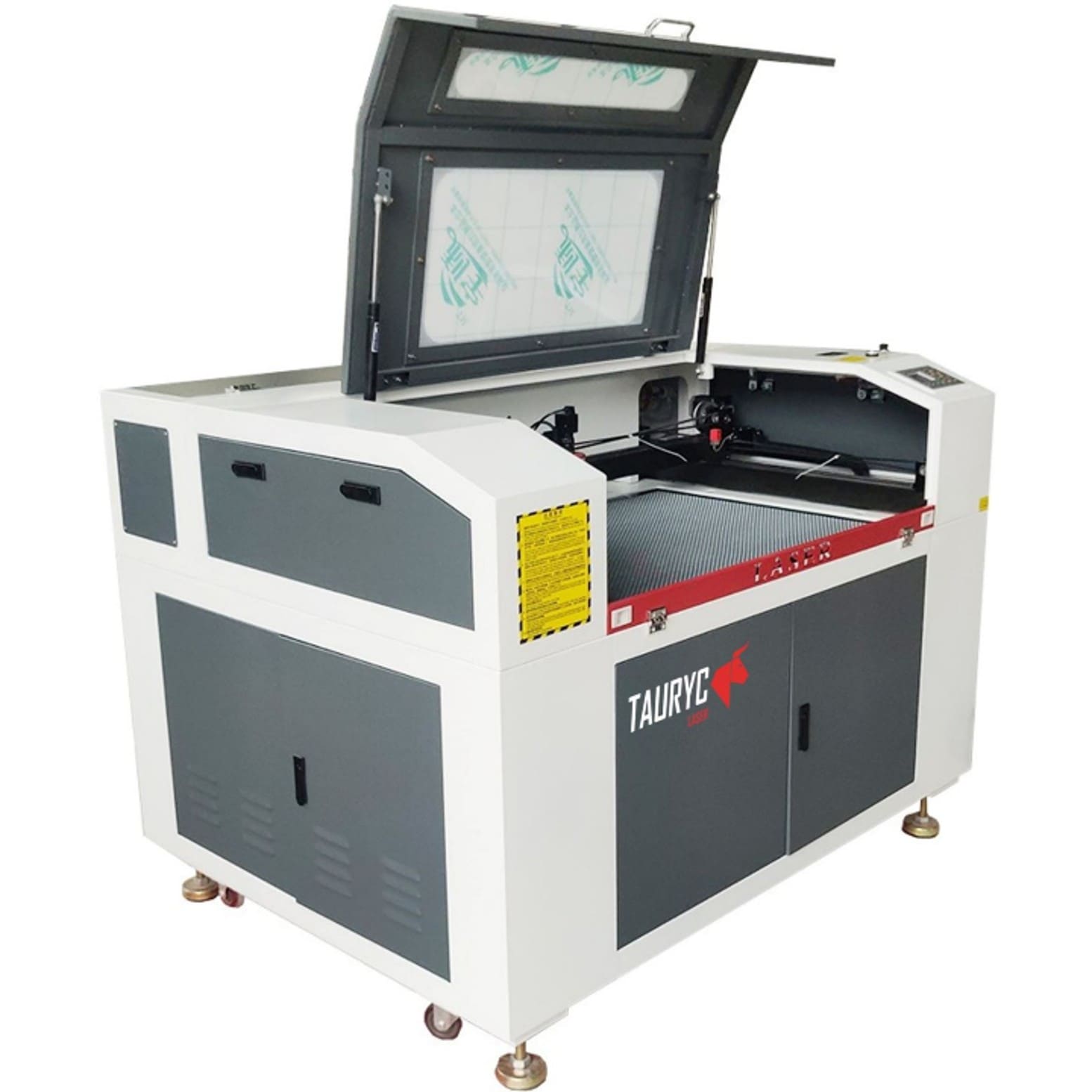
Image 4. Laser cutting machine.
Technical Specifications of the Laser Cutter
| Parameter |
Specification |
| Model |
Tauryc 9060 |
| Laser Type |
CO₂ Laser |
| Power |
100 W |
| Working Area |
60 × 90 cm |
| Controller |
Ruida 6445G |
| Manufacturing Country |
China |
We used RDWorks software, where I understood the importance of correctly
configuring parameters such as power, speed, number of passes, cutting
order, and layer assignment by color.
Through the tests performed, we characterized important aspects of the
machine, such as laser focus, real cutting power, optimal speed, kerf,
joint clearance, and the different types of cuts depending on the
material used.
The physical tests, especially the joint and tolerance tests, helped me
understand in a practical way how small variations of tenths of a
millimeter can make a big difference in the final fit of the pieces.
In conclusion, this experience helped me understand that the laser
cutter is not simply a machine that cuts. It is a tool that requires
technical knowledge, judgment, previous tests, and a strong focus on
safety.
As a recommendation for future group work, it is better to prepare the
designs and files in advance. In our case, it took many hours to complete
all the files, from the morning until late at night. Although it was very
exciting to spend the whole day working together, it is always better to
save time through planning.
II) Individual Assignment
2.1. Choosing the Material
First, I characterized the material that I would use to make my
parametric construction kit. I chose MDF, which stands for Medium
Density Fiberboard. MDF is a composite material made from wood fibers
and synthetic resins. It is characterized by its homogeneous structure
and smooth surface.
MDF is commonly used in digital fabrication for prototyping because its
uniform structure allows precise cuts and consistent engraving without
the irregularities found in natural wood grain. Its dimensional stability
makes it ideal for validating mechanical assemblies and press-fit
structures before moving to final materials.
The MDF sheet used for this assignment had a thickness of 2.6 mm.
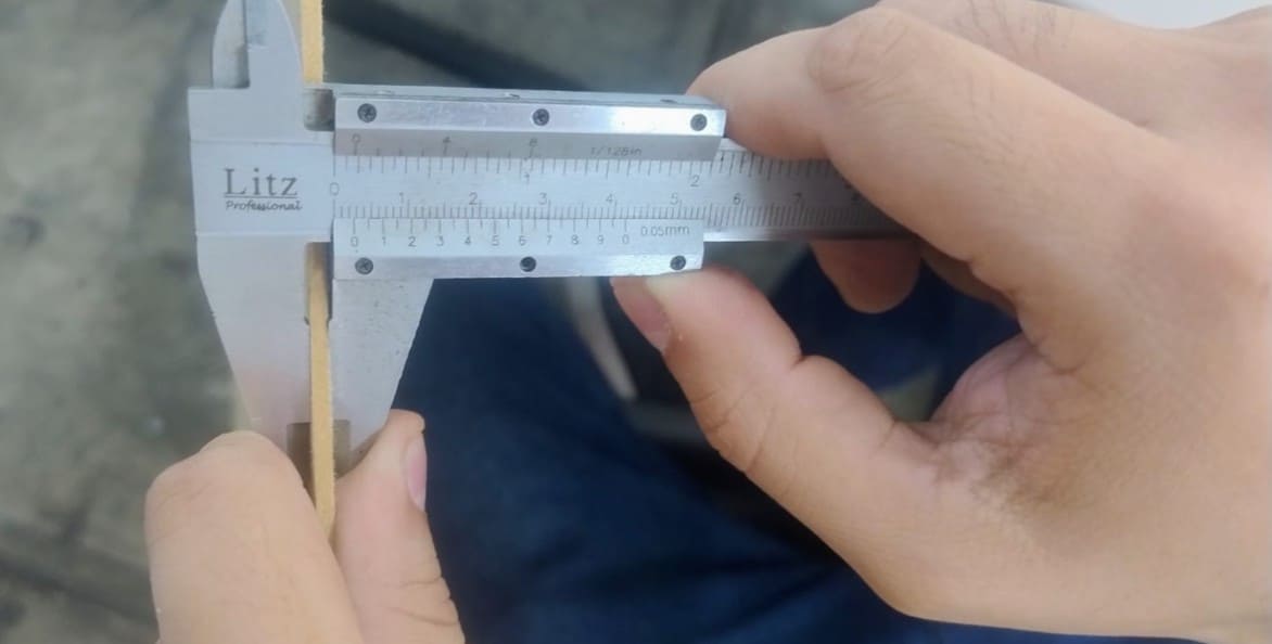
Image 5. Measuring the MDF material thickness with a caliper.
2.2. Designs and Tests
Calculating the kerf, or cutting compensation, is very important in
laser cutting. Kerf is the width of material that the laser removes while
cutting. If a piece needs to fit into a slot, this material loss must be
considered in the design.
The basic formula used was:
Final measurement = Desired measurement + Kerf.
For this group test, we designed a comb gauge to test the fitting
tolerance. Since the measured material thickness was 2.6 mm, we
increased and decreased the slot size by 0.1 mm until obtaining eleven
divisions, ranging from 2.0 mm to 3.0 mm.
To design the comb gauge, I used Autodesk Fusion. I had to be very
precise with the measurements to avoid errors. I started by drawing the
comb slots with different widths from 2.0 mm to 3.0 mm.
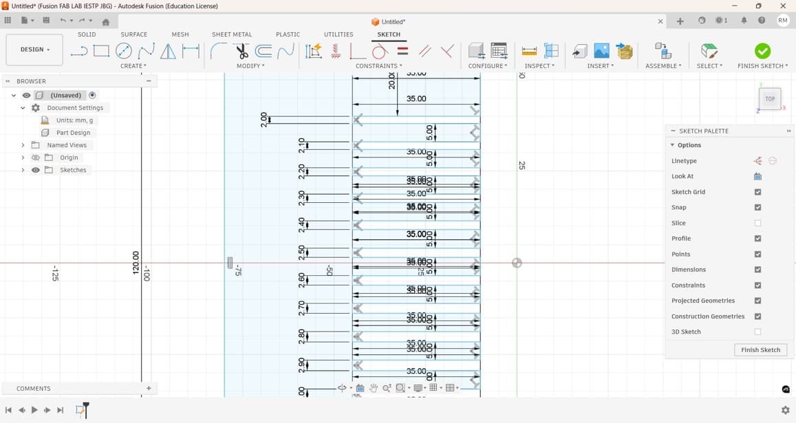
Image 6. Comb gauge design to test the joint fitting. This was very
useful for the construction of my parametric construction kit.
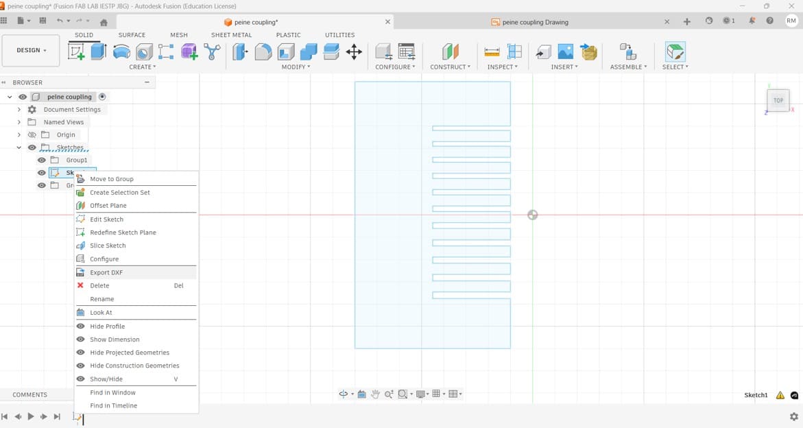
Image 7. After finishing the comb design, I exported it as a DXF file,
because this is the format accepted by the laser cutter software,
RDWorks.
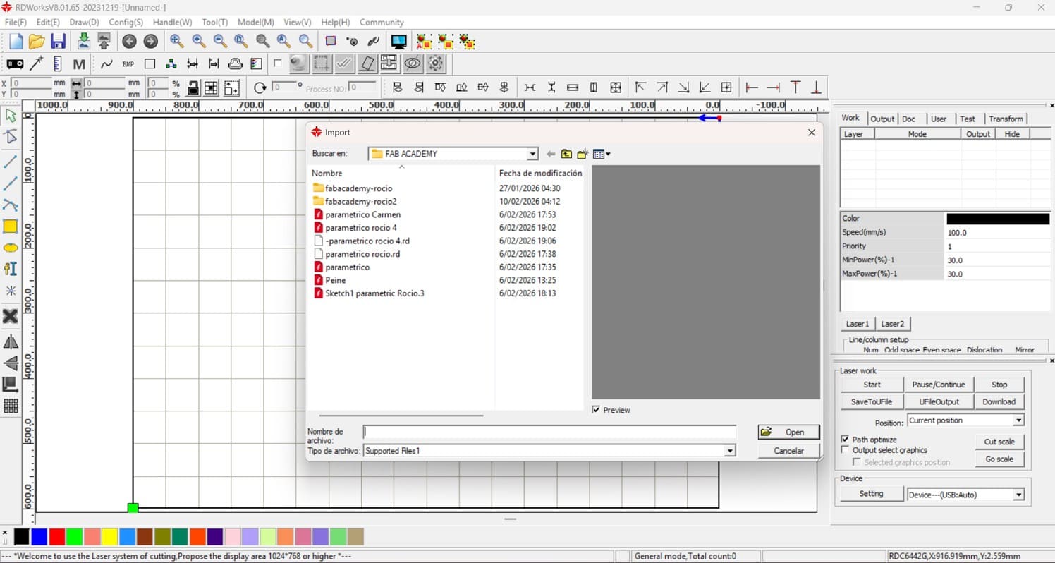
Image 8. After opening RDWorks, I imported the comb file to configure
speed, power, and the order of the engraving and cutting layers.
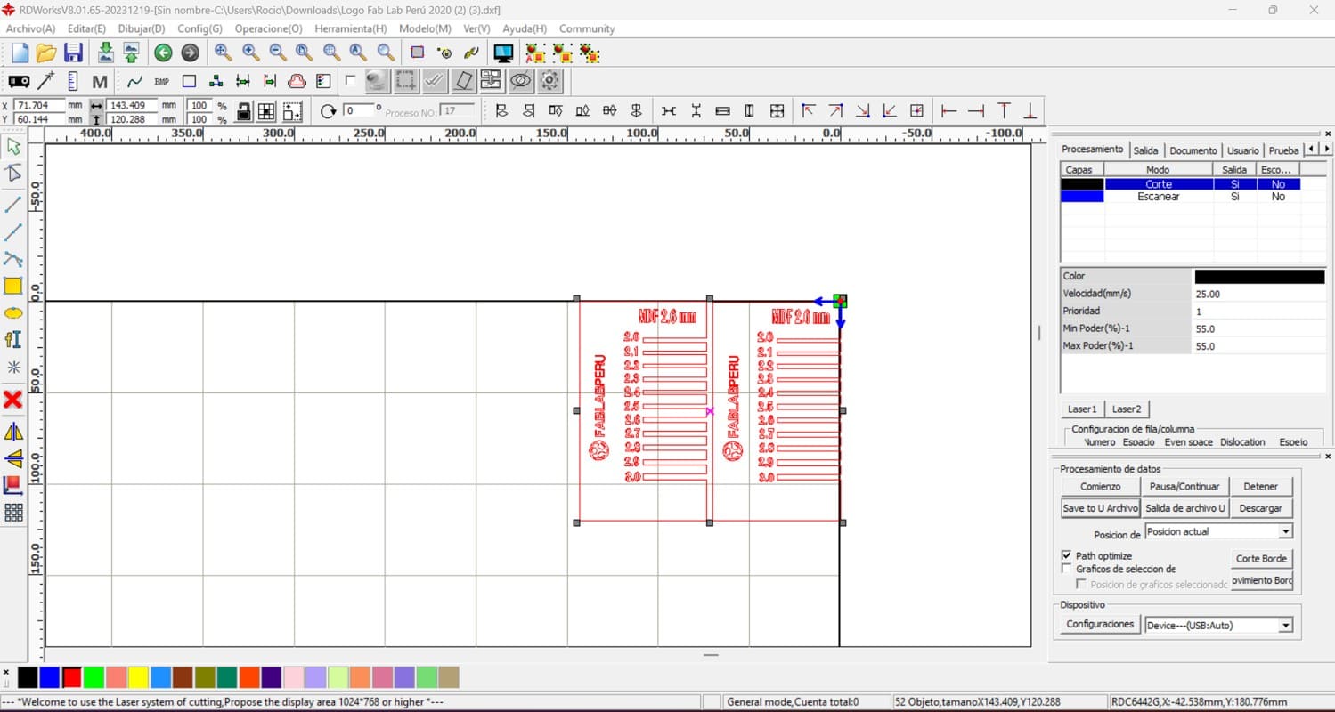
Image 9. The file was duplicated, and engraving text was added with
the material thickness, material type, and the FAB LAB Peru logo.
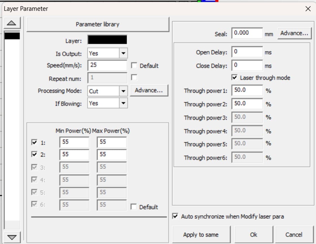
Image 10. Configuration of engraving and cutting parameters. For
engraving, the speed was 250 mm/s and the power was 25%. For cutting,
the speed was 25 mm/s and the power was 55%. Then, the file was saved
on a USB drive and taken to the laser cutting machine.
Testing a laser cutting machine is important to ensure that it works
correctly and that the settings are appropriate for each material and
specific job. Power and speed must be adjusted according to the material
used. In my case, I based my settings on the tests previously carried out
during the group assignment.
It is also necessary to adjust the height of the laser in relation to the
material. For this process, we used a 3D-printed stair-shaped calibration
tool, selecting the third level as the correct focus distance.
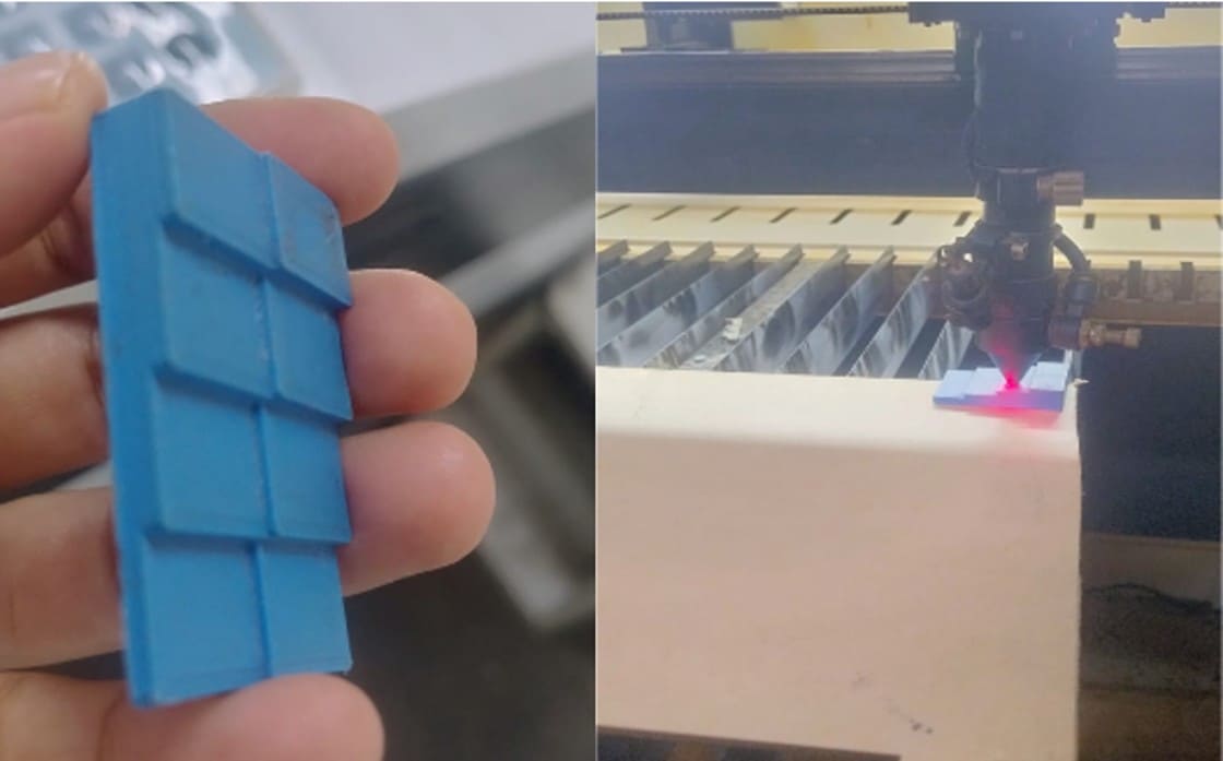
Image 11. Calibration of the distance between the laser and the material.
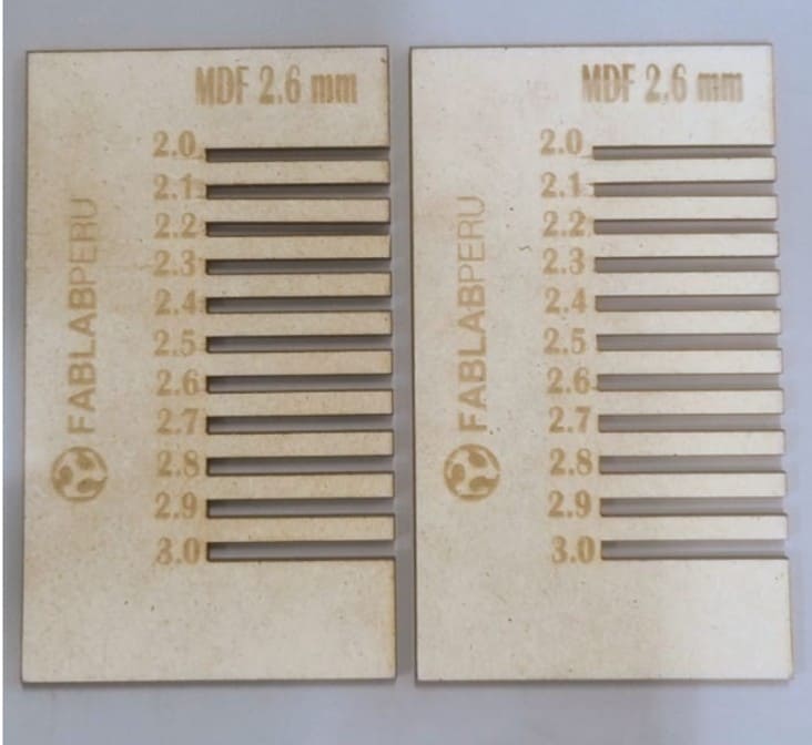
Image 12. Final result of the comb gauge. First, the engraving was
performed, and then the cutting process was completed.
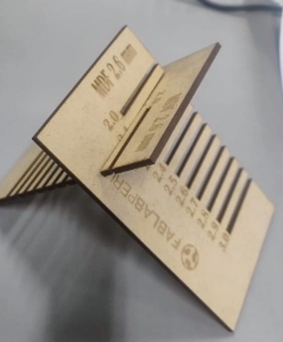
Image 13. Testing the press-fit joint.
2.3. Designing the Parametric Construction Kit
For the development of my parametric construction kit, I used Fusion 360.
I worked with MDF material with a thickness of 2.6 mm, and the parametric
figure I selected was a hexagon.
The first step was to define the parameters. The use of parameters in
Fusion 360 allows the geometry of the model to be defined through
mathematical variables instead of static values. By creating a parameter
table, I was able to assign names to critical dimensions, such as the
material thickness, kerf compensation, and tolerance.
This methodology is fundamental in digital fabrication because it allows
the entire design to update automatically if I decide to change the
material or if the fitting tests show that the tolerances need to be
corrected. Instead of redrawing each piece, I only modify the numerical
value in the table, and the model adjusts the slots, joints, and
assemblies in a coherent and precise way.
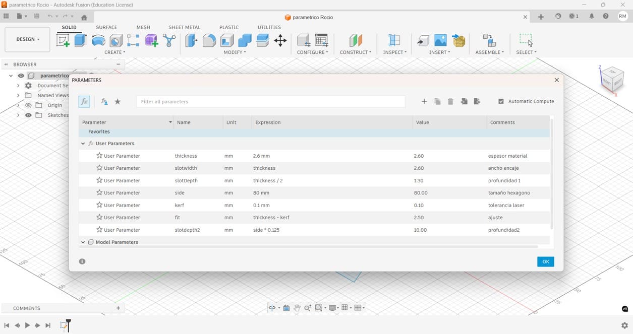
Image 14. Defining parameters with mathematical equations that can
later be modified and adapted to the material used for laser cutting.
After defining the parameters, I created the base shape of the kit.
I started by drawing a hexagon from the center, because this allowed me
to control the geometry symmetrically and keep the design organized.
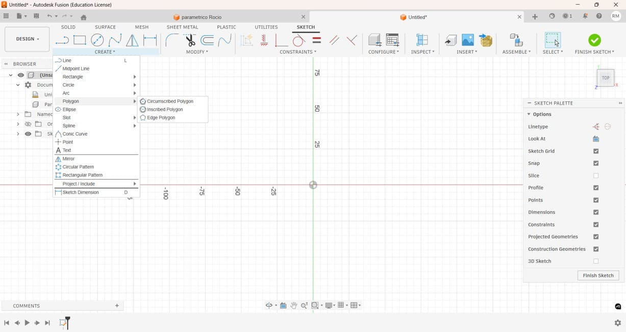
Image 15. Creating a hexagon and drawing it from the center point.
Then, I assigned parametric names to the dimensions. This step was very
important because it allowed me to control the size of the hexagon and
the slot dimensions using the parameters previously created.

Image 16. Defining the dimensions using the parametric values created
in Fusion 360.
Next, I drew a rectangle using the MDF thickness as the width and around
20% of the total diameter as the length. This slot dimension was chosen
to obtain a good press-fit connection between the pieces.
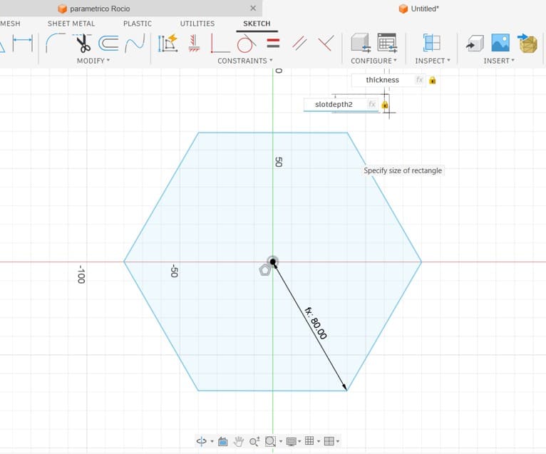
Image 17. Drawing a rectangle using the wood thickness as the slot
width and approximately 20% of the total diameter as the slot length.
After creating the rectangle, I moved it to the center of one of the
sides of the hexagon. This position allowed the slot to be aligned with
the edge of the piece and prepared it for the following replication step.
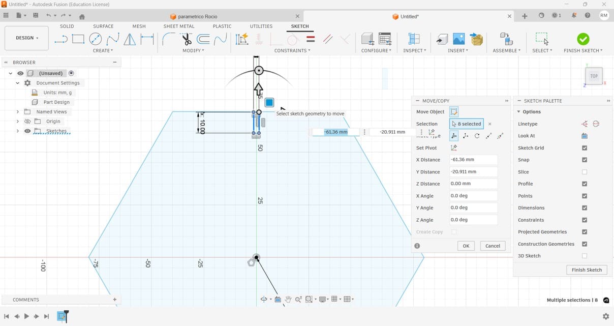
Image 18. Moving the rectangle to the center of one side of the
hexagon.
To replicate the same slot on all sides of the hexagon, I used the
circular pattern tool. This was useful because it allowed me to create
repeated slots with the same dimensions and equal spacing.
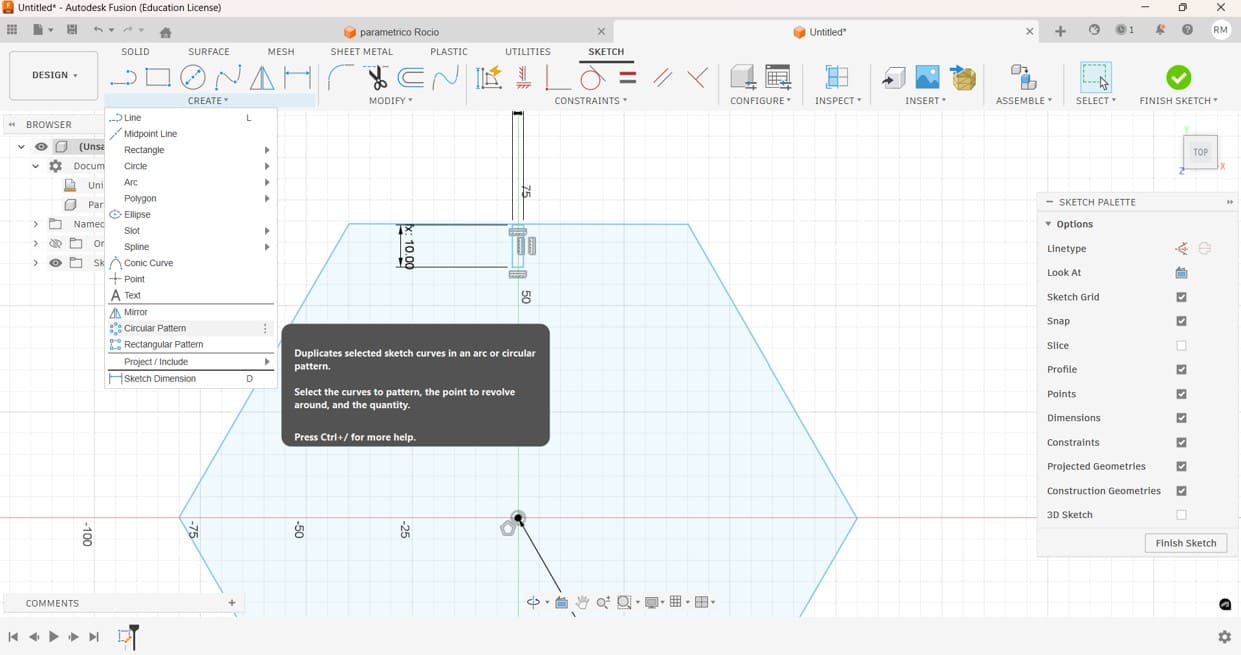
Image 19. Creating a circular pattern of the rectangle so that it
could be replicated on all sides of the hexagon.
After applying the circular pattern, the hexagon had slots on each side.
This completed the main geometry of the parametric construction kit and
prepared the model for the final fitting details.
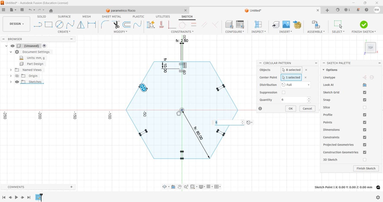
Image 20. Circular pattern completed. The rectangular slots were
replicated on each side of the hexagon.
To improve the insertion of the pieces, I decided to add chamfers to the
slots. Chamfers help guide the pieces during assembly and reduce the
force required when creating press-fit joints.
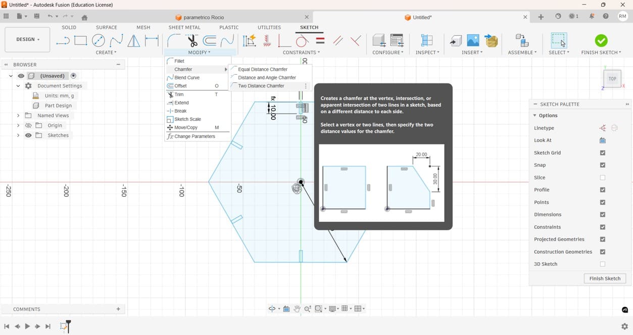
Image 21. Creating chamfers to improve the fit of the joints.
At this stage, I was not completely sure where the chamfer should be
positioned.
Since I was unsure about the best location for the chamfer, I tested
different alternatives by placing it on both the internal and external
edges of the slot. This allowed me to compare the assembly performance
and evaluate which configuration worked better.
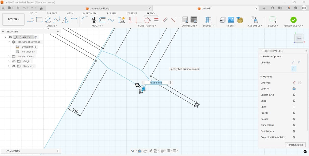
Image 22. Testing chamfers on both the internal and external sides of
the slot.
Once the parametric design was completed, the file was exported in DXF
format to be imported into RDWorks and configured for laser cutting.
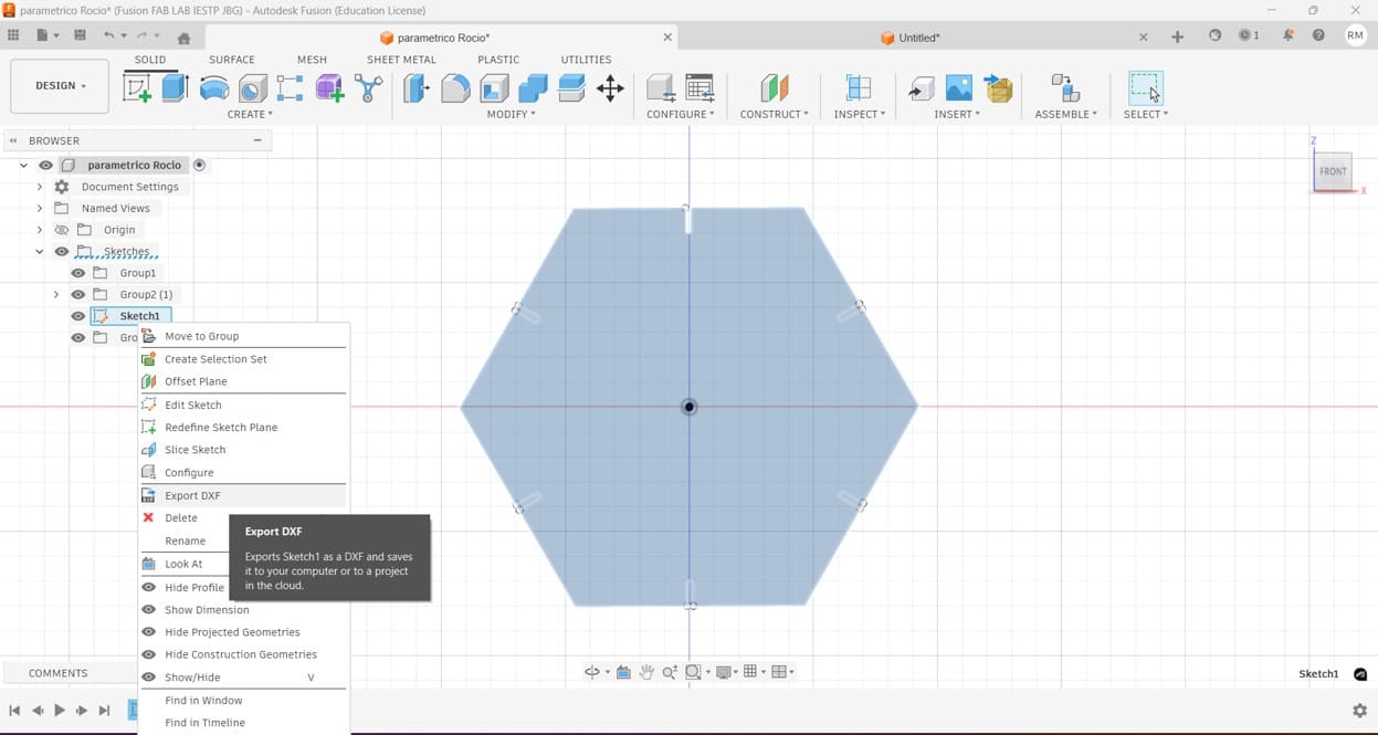
Image 23. Exporting the completed parametric design as a DXF file.
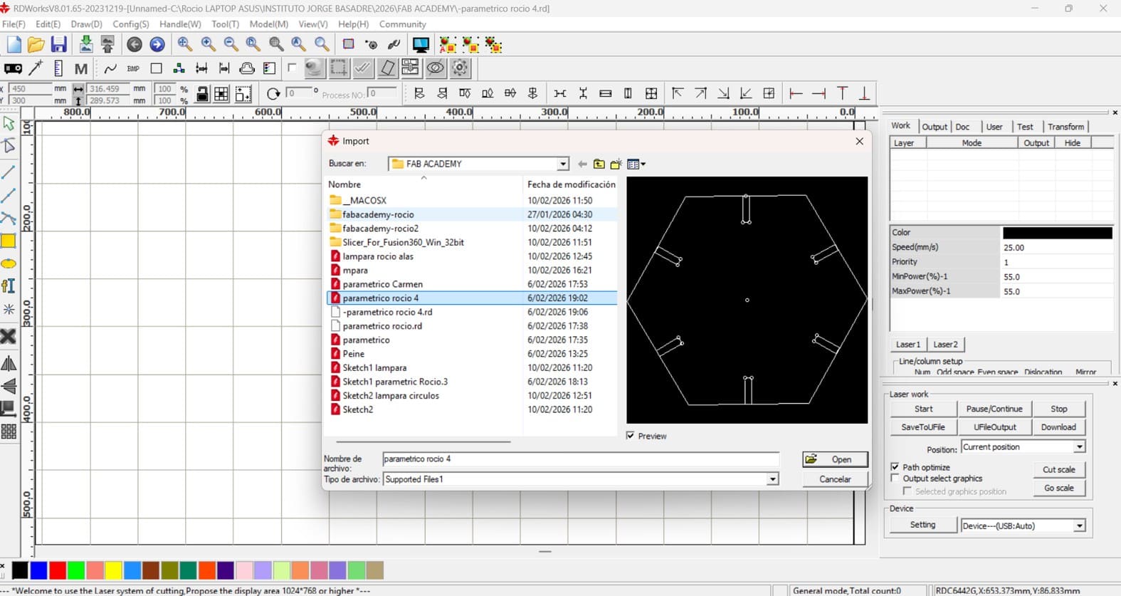
Image 24. Importing the DXF file generated in Fusion 360 into
RDWorks.
After importing the file, several copies were arranged on the working
area and the cutting parameters were configured according to the results
obtained during the characterization process.
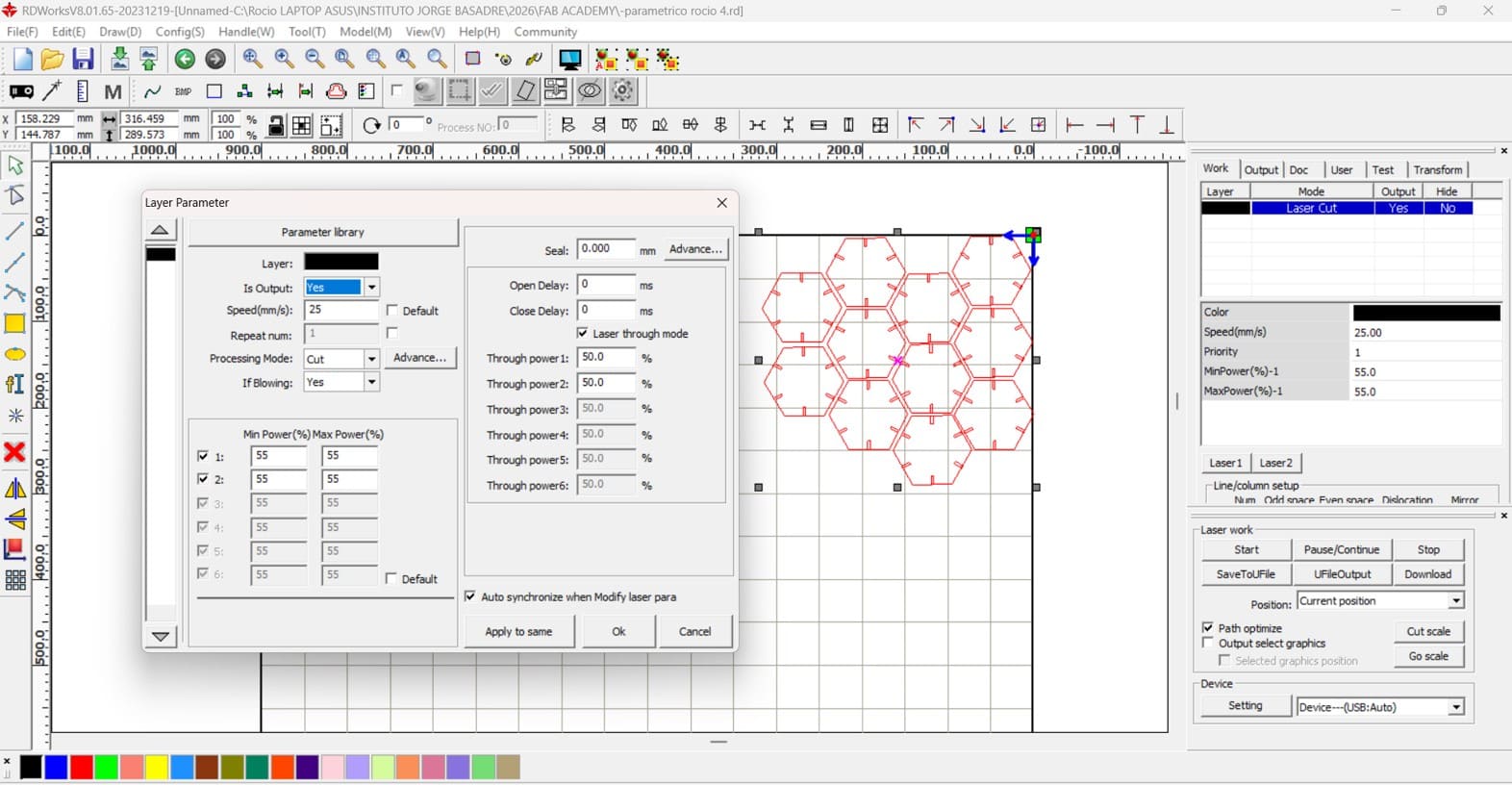
Image 25. Preparing multiple copies and configuring cutting speed and
power.
Laser Cutting Parameters
MDF was used as the primary material for manufacturing the press-fit
construction kit. Several tests were performed in order to obtain clean,
accurate, and repeatable cuts.
| Parameter |
Value |
| Material |
MDF |
| Thickness |
2.6 mm |
| Machine |
Storm 600 CO₂ Laser Cutter |
| Design Software |
Fusion 360 |
| Control Software |
RDWorks / RDCAM |
| Cutting Speed |
25 mm/s |
| Minimum Power |
55% |
| Maximum Power |
55% |
| Air Assist |
Enabled |
| Processing Mode |
Cut |
| Repeat Count |
1 |
The RDWorks software used with this machine does not include a frequency
adjustment parameter for standard cutting operations. Therefore, the
cutting process was configured mainly through speed and laser power.
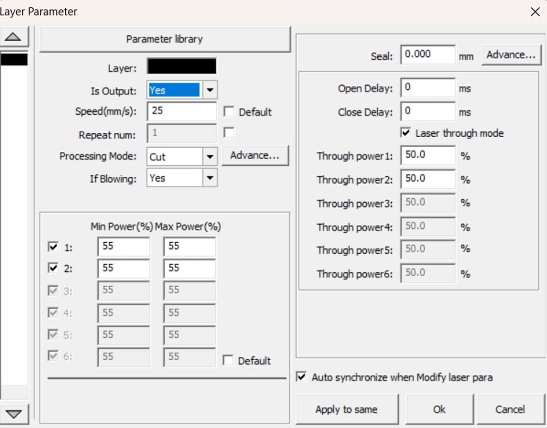
Image 26. Final laser cutting parameters.
Once the configuration was completed, the file was saved onto a USB
drive and transferred to the laser cutting machine.
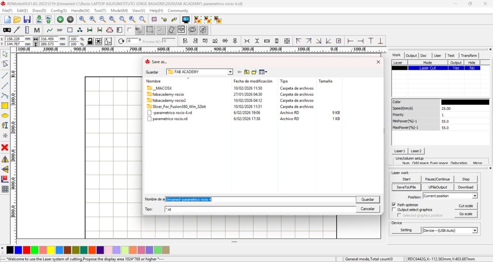
Image 27. Saving the cutting file onto a USB drive.
Loading the Cutting File
Before starting the cutting process, the laser head was manually focused
using the machine's focusing tool. The distance between the nozzle and
the material surface was adjusted according to the recommended focal
distance to ensure clean and precise cuts.
After inserting the USB drive into the machine, I used the control panel
to locate and select the cutting file. The interface displayed
information such as file name, coordinates, speed, and power settings,
allowing me to verify that everything was configured correctly before
starting the job.
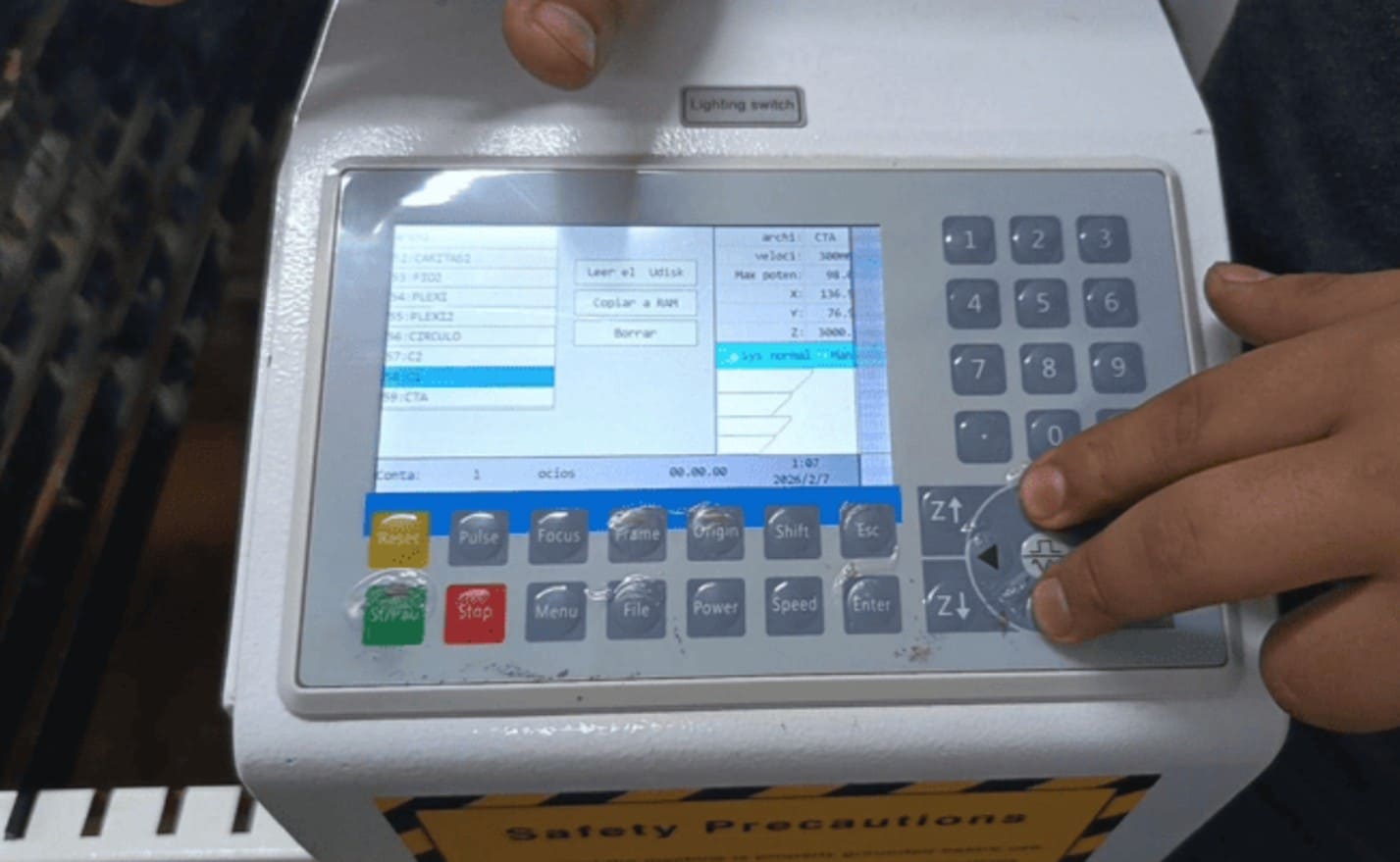
Image 28. Loading the cutting file from the USB drive.
Vector Cutting Setup and Execution
After selecting the file from the control panel, the MDF sheet was
placed on the laser bed and the laser head was positioned at the
starting point. An alignment test was performed to verify the cutting
area and ensure proper positioning.
Once everything was confirmed, the cutting process was started. During
the operation, constant supervision was maintained to ensure safety and
cutting quality.
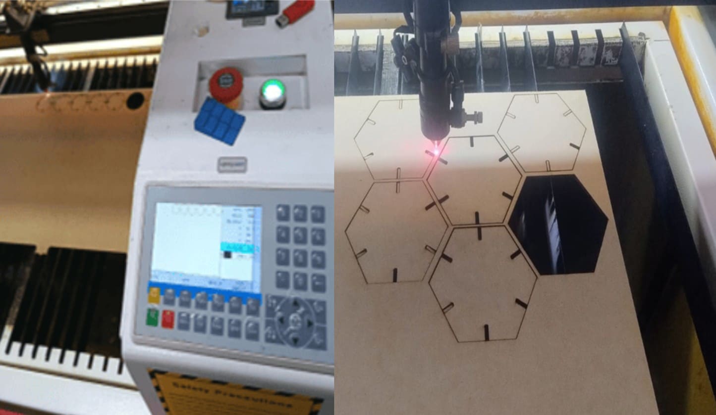
Image 29. Performing alignment and cutting verification tests.
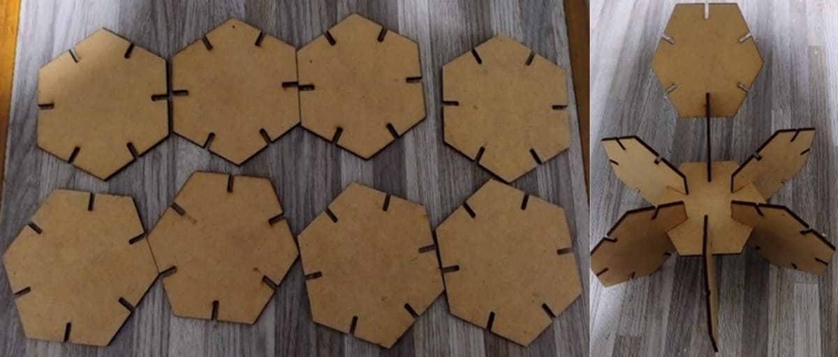
Image 30. Finished pieces after laser cutting.
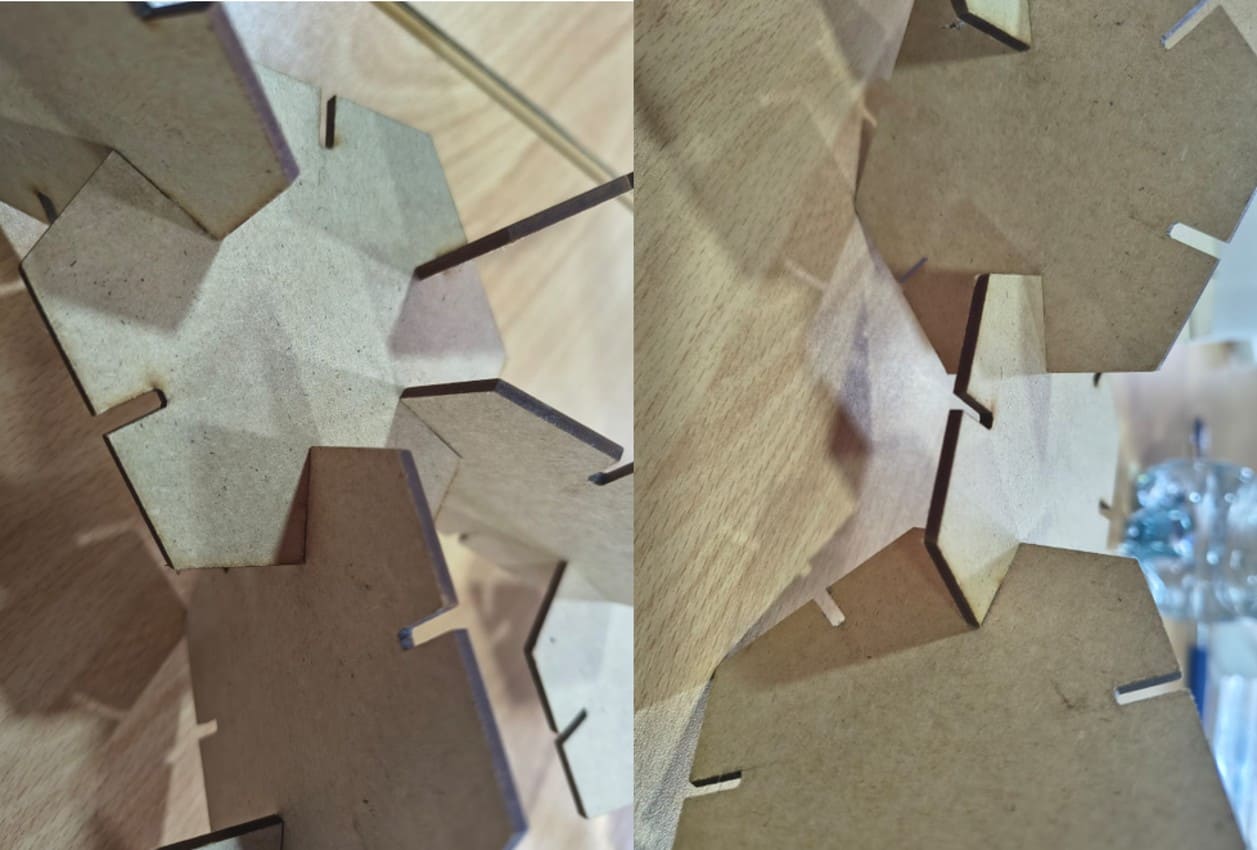
Image 31. Testing the fit and assembly of the pieces.
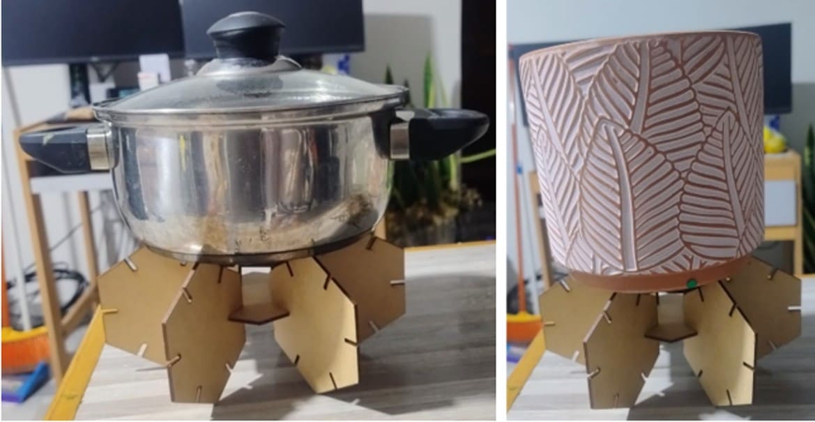
Image 32. Additional assembly tests of the parametric construction
kit.
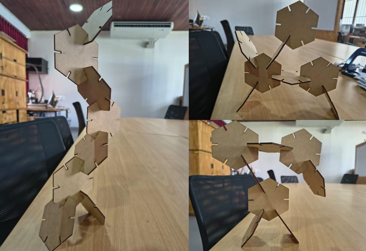
Image 33. Final assemblies created using the hexagonal construction
kit.
2.4. Vinyl Cutting
Inspiration and Recovery of a Vinyl Cutter
During this stage of Fab Academy, I had the opportunity to closely
observe the recovery process of a Roland vinyl cutter that had been
unused due to incompatible drivers with Windows 11 and missing original
cables.
My classmate took on the challenge of bringing this machine back to life.
Seeing how he overcame these technical barriers through research and
perseverance helped me understand that apparently obsolete hardware can
become valuable again with the right knowledge.
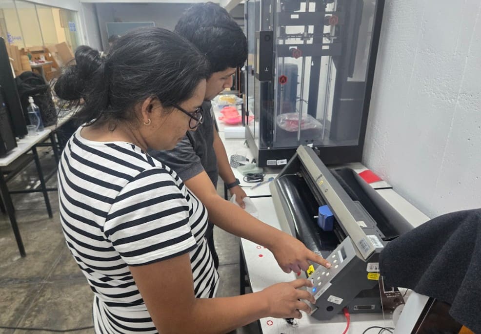
Image 34. Understanding how the vinyl cutter works after its recovery.
This restoration process was especially inspiring because at Fab Lab
Madre de Dios we have a machine with similar connectivity and driver
issues. Observing the successful configuration and workflow gave me
confidence to return and lead the setup of our own equipment.
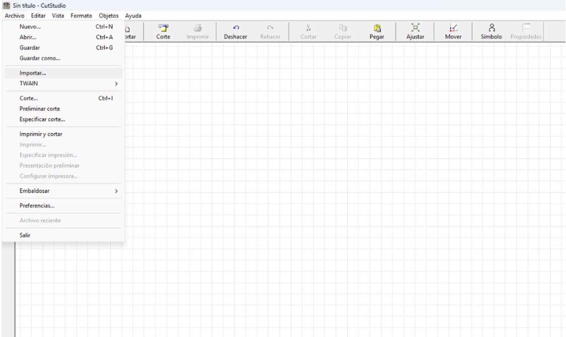
Image 35. Using CutStudio to design a butterfly.
To test the operational machine, I worked on the design of a butterfly,
a symbol that I wanted to take back to my region. The design was prepared
in a vector workspace, taking care of each node to ensure a smooth cut.
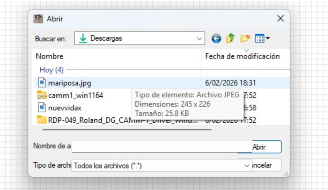
Image 36. Importing my butterfly drawing in JPG format.
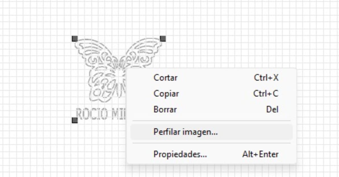
Image 37. Tracing the image to obtain precise vectors for vinyl
cutting.
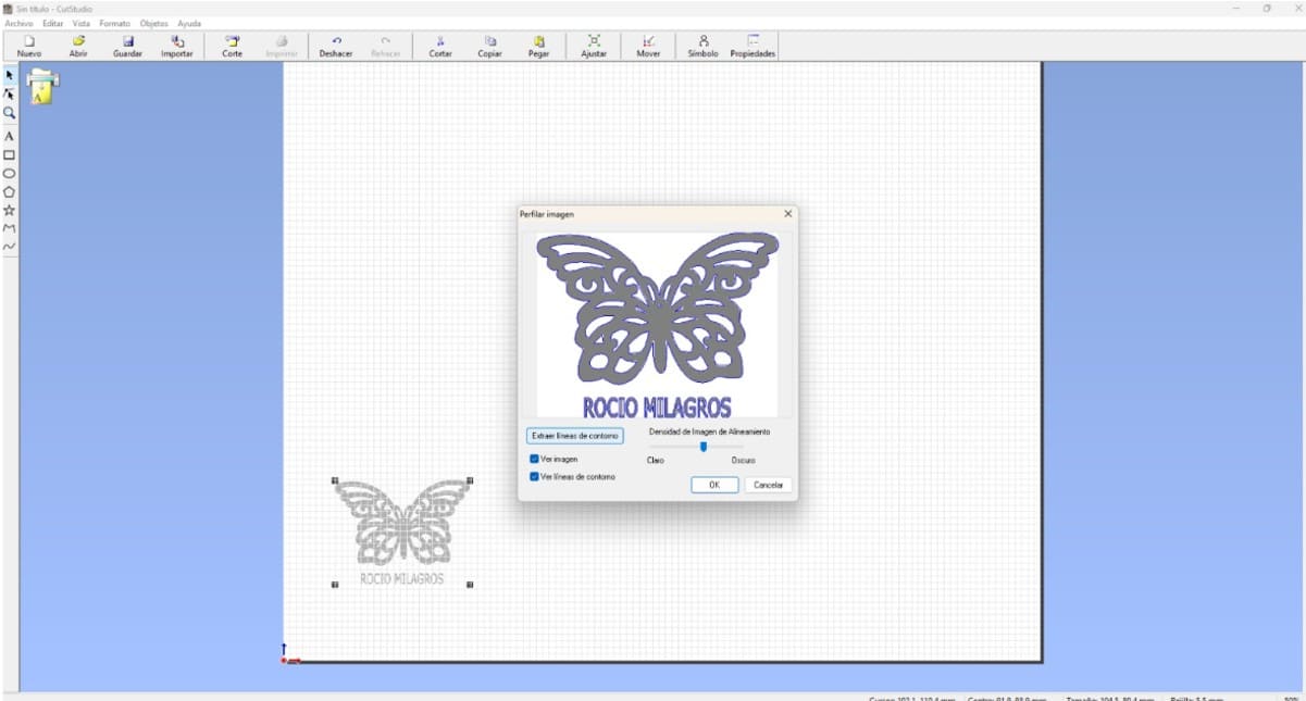
Image 38. Butterfly design ready to be sent to the vinyl cutter.
The physical testing phase was also very important. After several
attempts where the cut was not perfect, technical adjustments were made
until the ideal blade force was found. A blade force value of 80 allowed
the butterfly to be cut cleanly without damaging the vinyl backing.
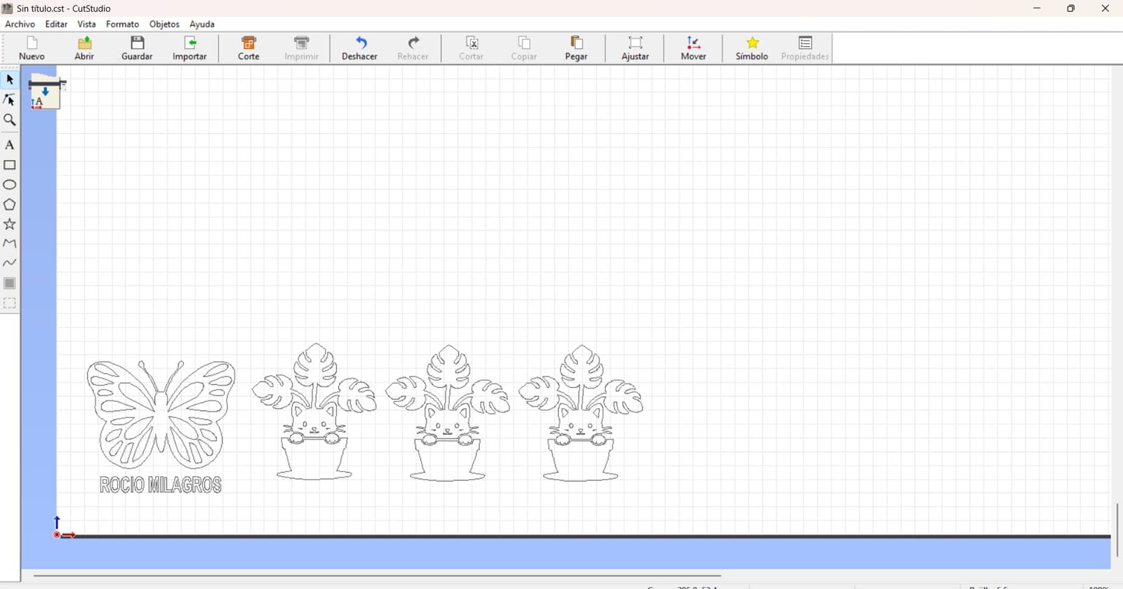
Image 39. Butterfly and cat designs ready for cutting.
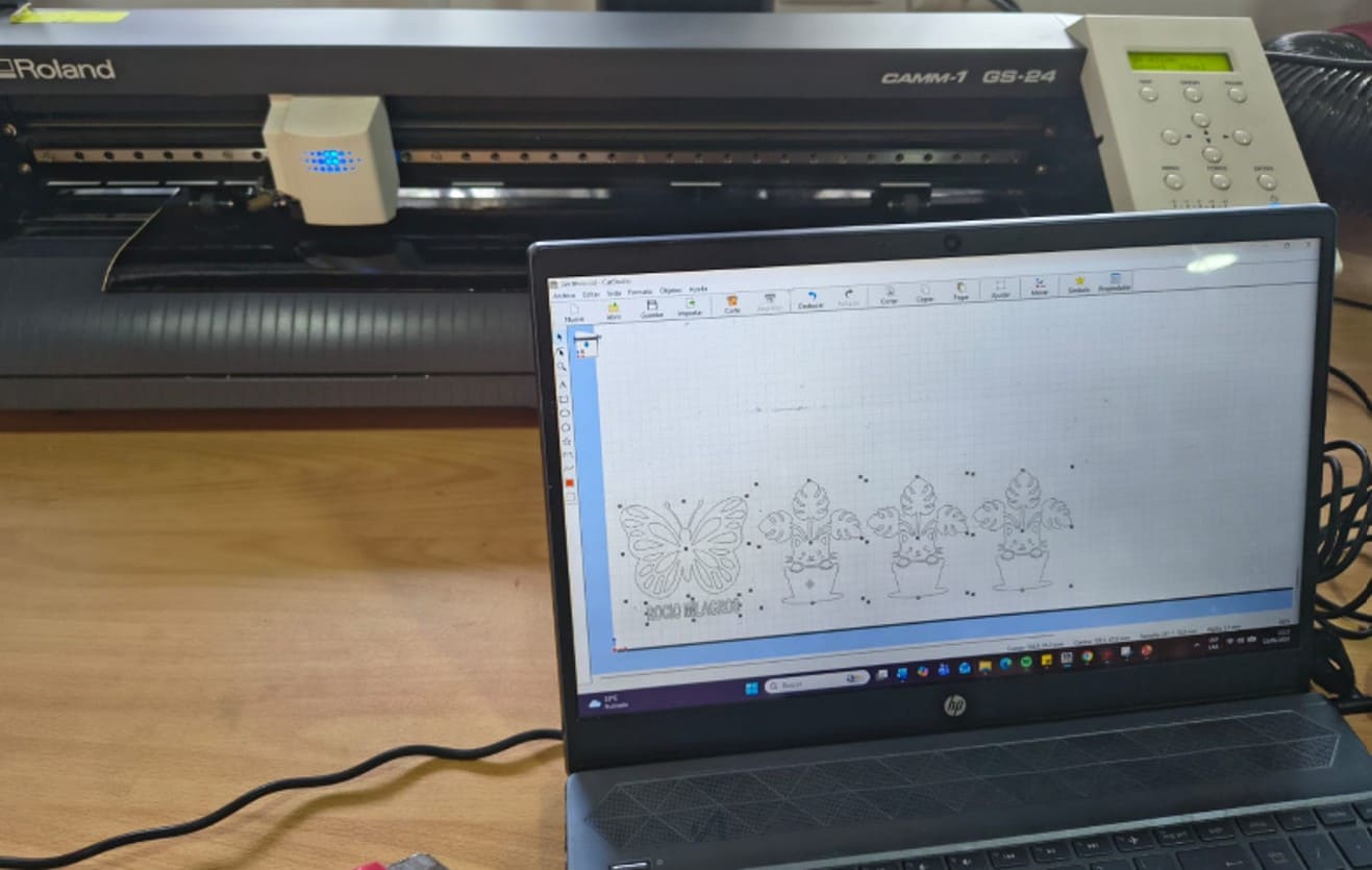
Image 40. Vinyl cutting process.
Post-Cutting Vinyl Process
Once the vinyl cutting process was completed, it was necessary to
perform several additional steps before applying the design to the final
surface.
Step 1: Removing Excess Material (Weeding)
The excess vinyl was carefully removed using a weeding tool or fine
tweezers. This process allowed me to keep only the parts of the design
that would later be transferred.
Special care was taken with small letters and fine details to avoid
damaging the design.
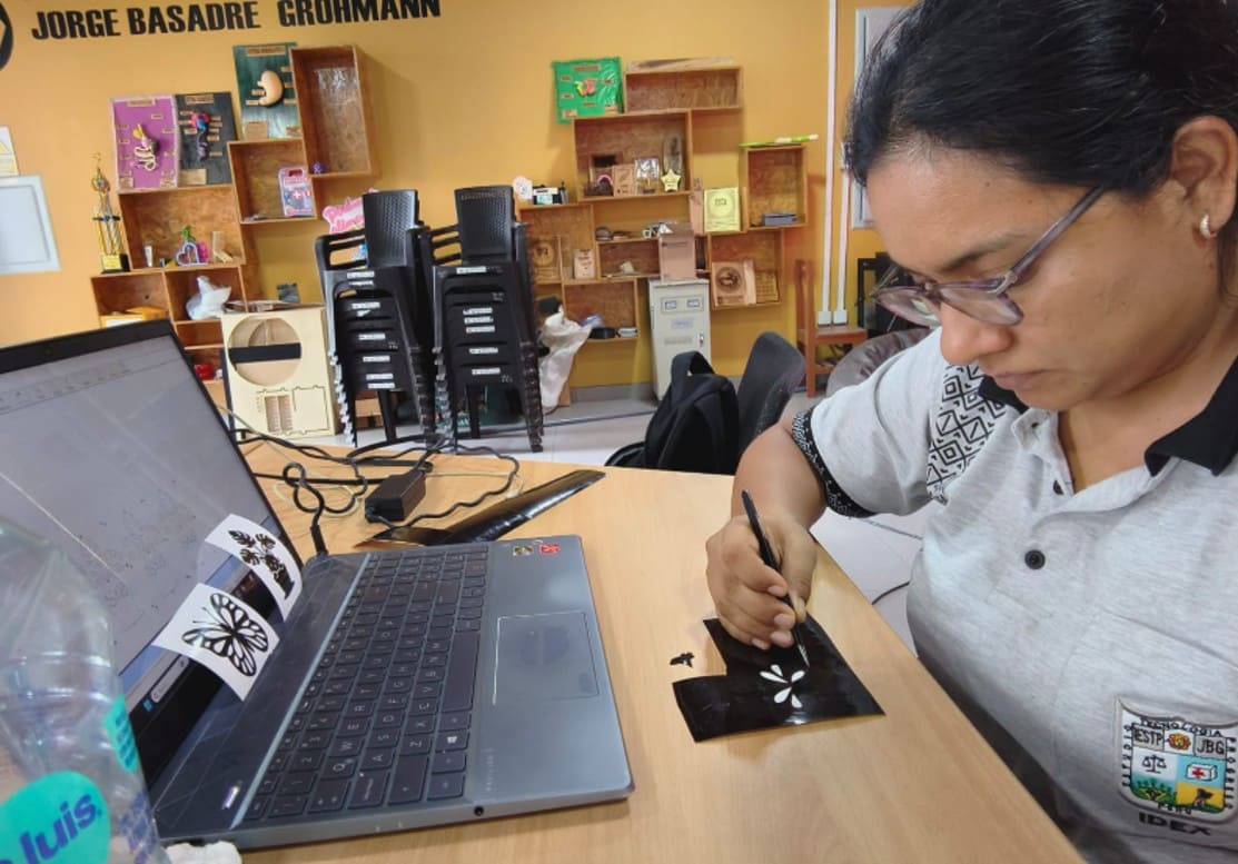
Image 41. Removing the excess vinyl material.
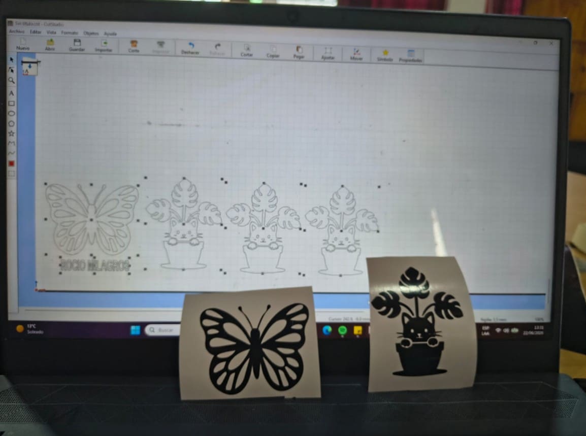
Image 42. Designs ready after removing the excess material.
Step 2: Transfer Tape Application
After weeding, I proceeded to transfer the design. Since I did not have
commercial transfer tape, I used transparent packing tape as an
alternative.
During the first attempt, the tape was applied directly onto the vinyl.
However, the adhesion was too strong, causing the design to stick
completely to the tape and several parts to break during the transfer
process.
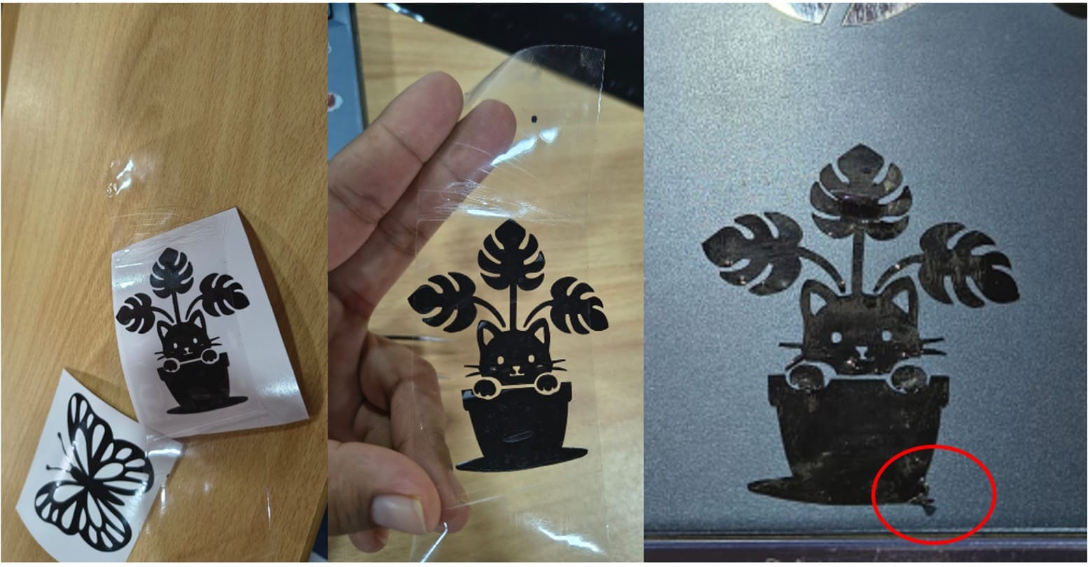
Image 43. First attempt using fresh packing tape. The adhesion was too
strong and part of the design broke.
To solve this problem, I reduced the tape adhesion by first sticking it
onto a clean fabric surface. After this, the tape was able to hold the
design properly without damaging it, keeping all elements aligned and
making it easier to transfer the vinyl to the application surface.
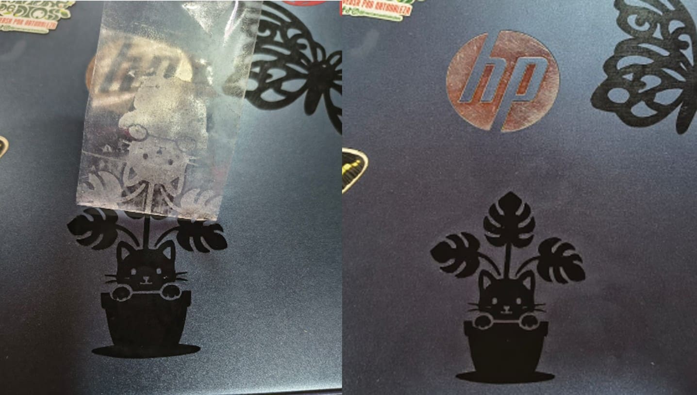
Image 44. Packing tape with reduced adhesion after being applied first
onto fabric. This allowed the cat design to be transferred successfully.
Step 3: Surface Preparation
Before applying the vinyl, the laptop surface was cleaned to remove
dust, grease, and fingerprints. This improved vinyl adhesion and reduced
the possibility of air bubbles.
Step 4: Vinyl Application
The transfer tape with the design was carefully placed onto the laptop.
Then, uniform pressure was applied using a plastic scraper to ensure
proper adhesion.
Step 5: Removing the Transfer Tape
Finally, the transfer tape was slowly removed at a low angle. The design
remained attached to the laptop surface, successfully completing the
application process.
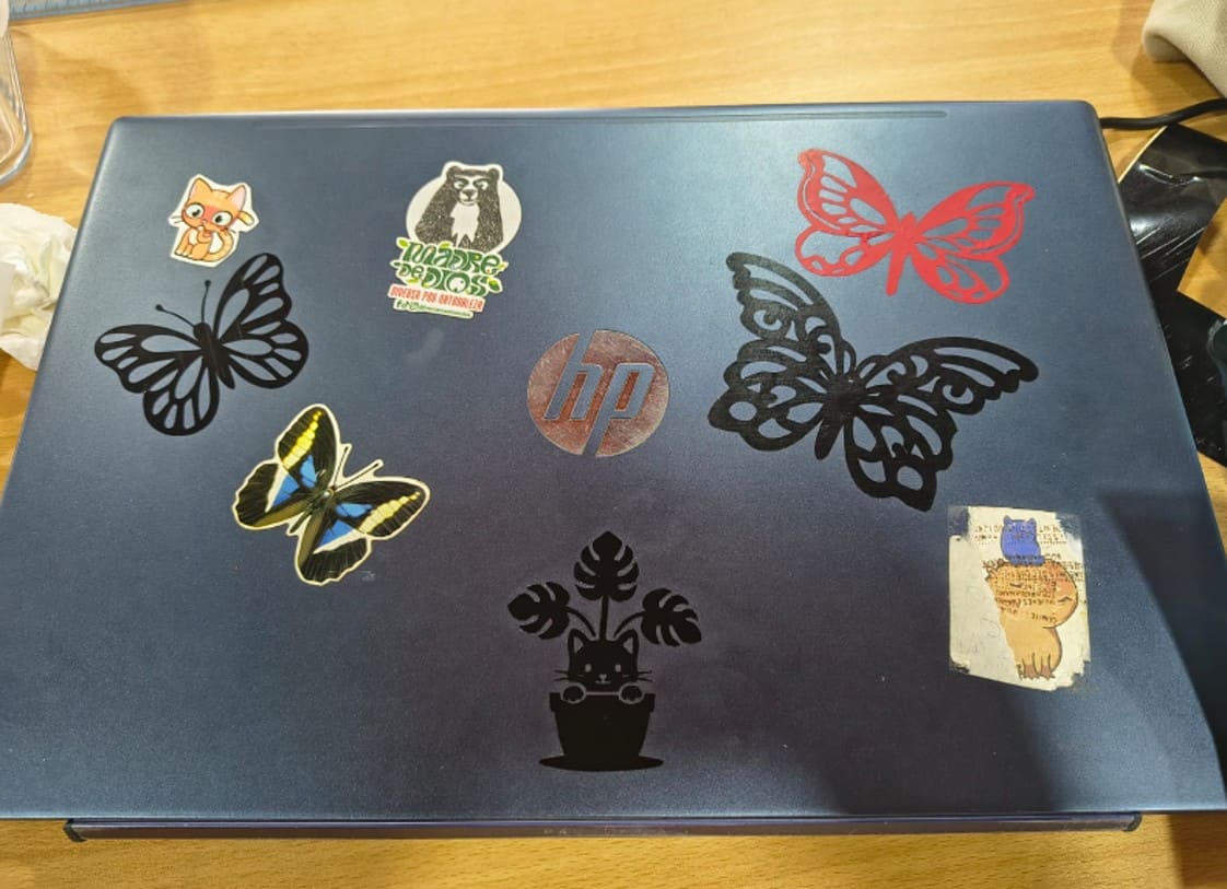
Image 45. Final result after applying the vinyl design.
Download Files
Precautions Considered
- Check the correct orientation of the design before cutting.
- Verify the dimensions before sending the file to the machine.
- Remove the excess vinyl carefully to avoid damaging the design.
- Clean the application surface properly before applying the vinyl.
- Apply uniform pressure to avoid air bubbles.
- Remove the transfer tape slowly to prevent the vinyl from lifting.
Final Reflection
This unit was fundamental for understanding that digital fabrication
does not begin at the machine, but in the logic of design and technical
problem solving. Learning the difference between parametric, vector, and
raster design gave me a conceptual toolkit to choose the best production
path.
One of my greatest lessons came from observation and collaboration:
seeing how unused technology can be recovered through technical
persistence. This gave me a renewed vision for Fab Lab Madre de Dios,
where hardware limitations can become temporary challenges that are
overcome with shared knowledge.
During the vinyl transfer process, I also faced difficulties because I did
not have commercial transfer tape. The first attempt using transparent
packing tape did not work well because the tape adhered too strongly and
damaged part of the design. However, this problem allowed me to find a
practical solution by reducing the tape adhesion on fabric before using
it again.
This experience helped me develop not only technical skills, but also a
problem-solving mindset. Now I feel more prepared to design objects,
manage equipment, optimize fabrication workflows, and activate tools
that can benefit my community.