I) Group Assignment
The group work was carried out at the FAB LAB of Universidad del Pacífico. First, we worked on making both the 3D printed mold and the machined mold. This was done on Friday, April 24.
Compare Printing vs Milling Molds
Milling Molds
For this group assignment, we worked with the design of the Virgin of Guadalupe, which we downloaded in STL format from this page: Virgin candle chibi kawai model. Once we had the STL design, we followed this workflow:
- We imported the 3D design in .OBJ format into Blender.
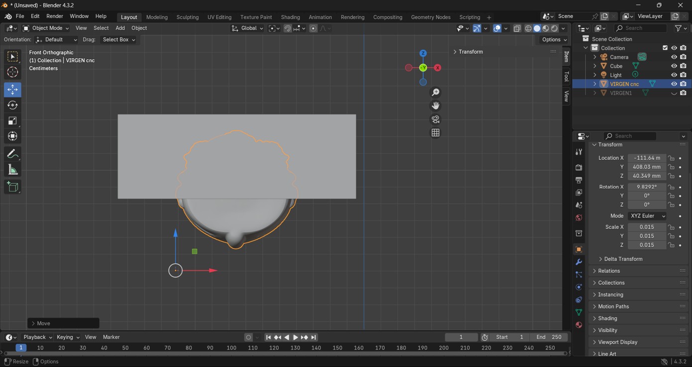
- We measured and scaled our 3D object proportionally.
- We drew a rectangular cube simulating the material to be machined.
- We moved and centered our figure with the material.
- In Edit Mode, we selected the top face and with the “I” key we made an inward offset.
- With the Extrude command, we subtracted the block almost halfway down our figure.
- In Edit Mode, we deleted the excess below the figure.
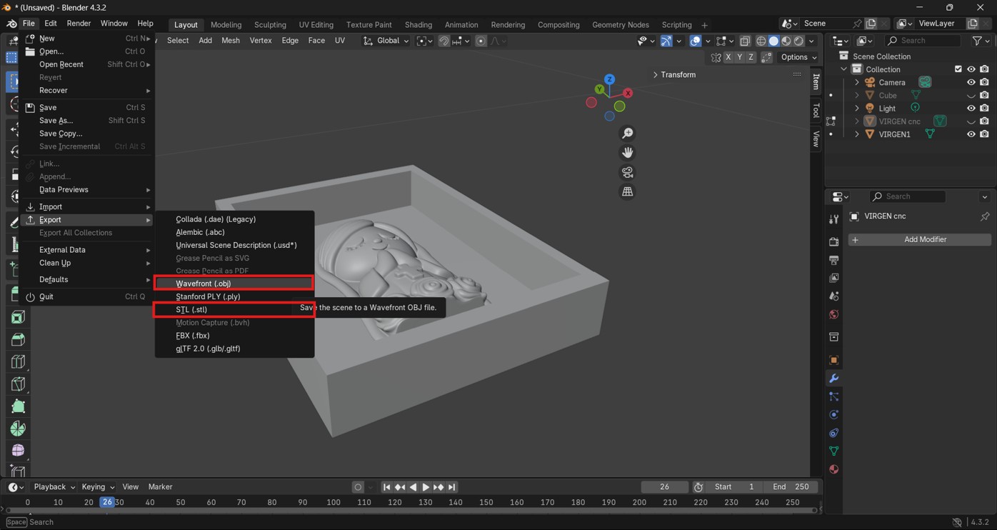
- We exported the mold either in .OBJ or .STL format to be able to machine it in Aspire.
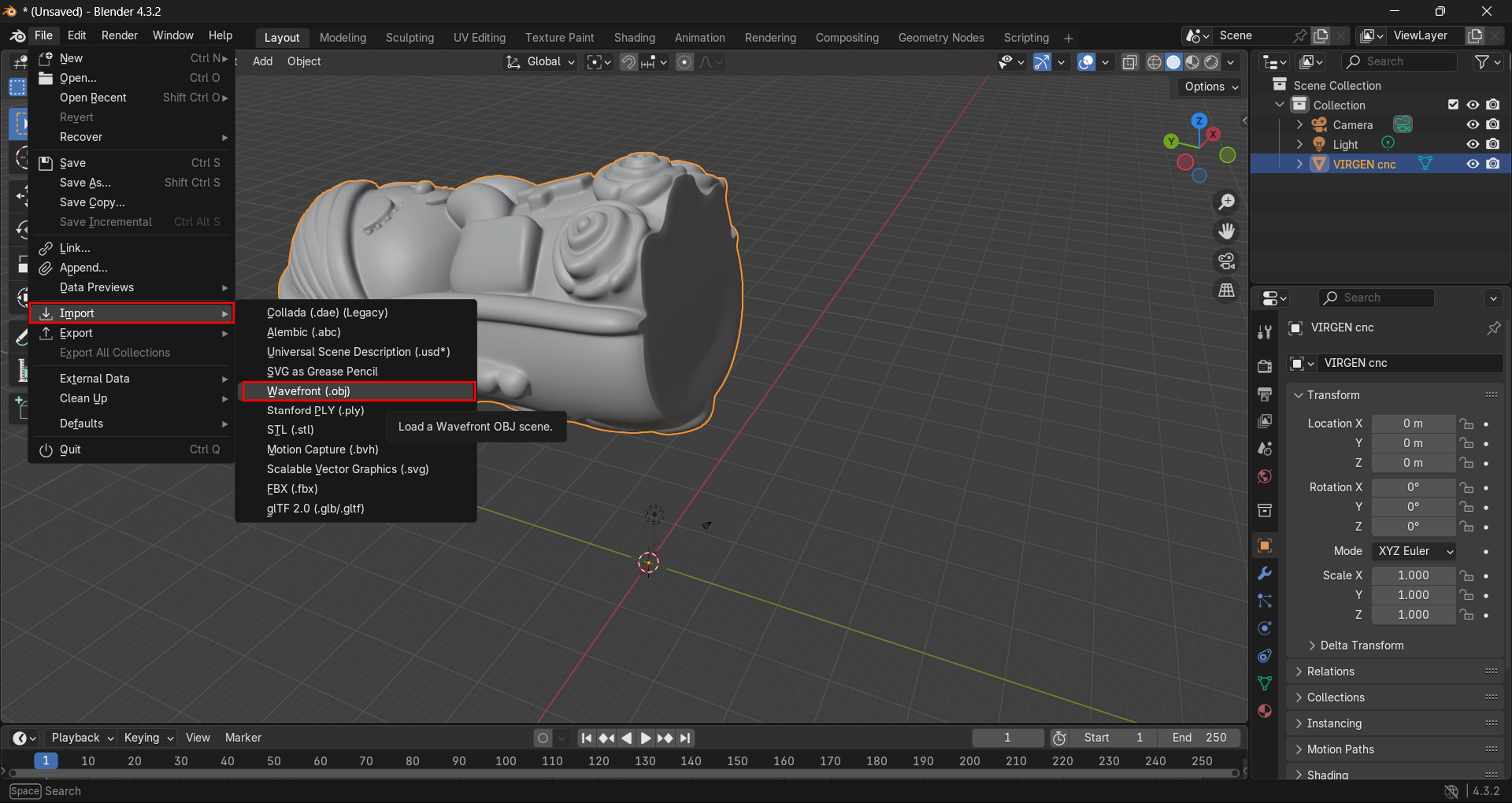
Img. 1: We imported the 3D design in .OBJ format into Blender.
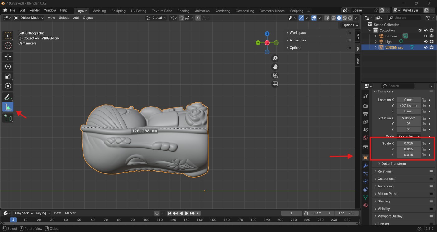
Img. 2: We measured and scaled our 3D object proportionally.
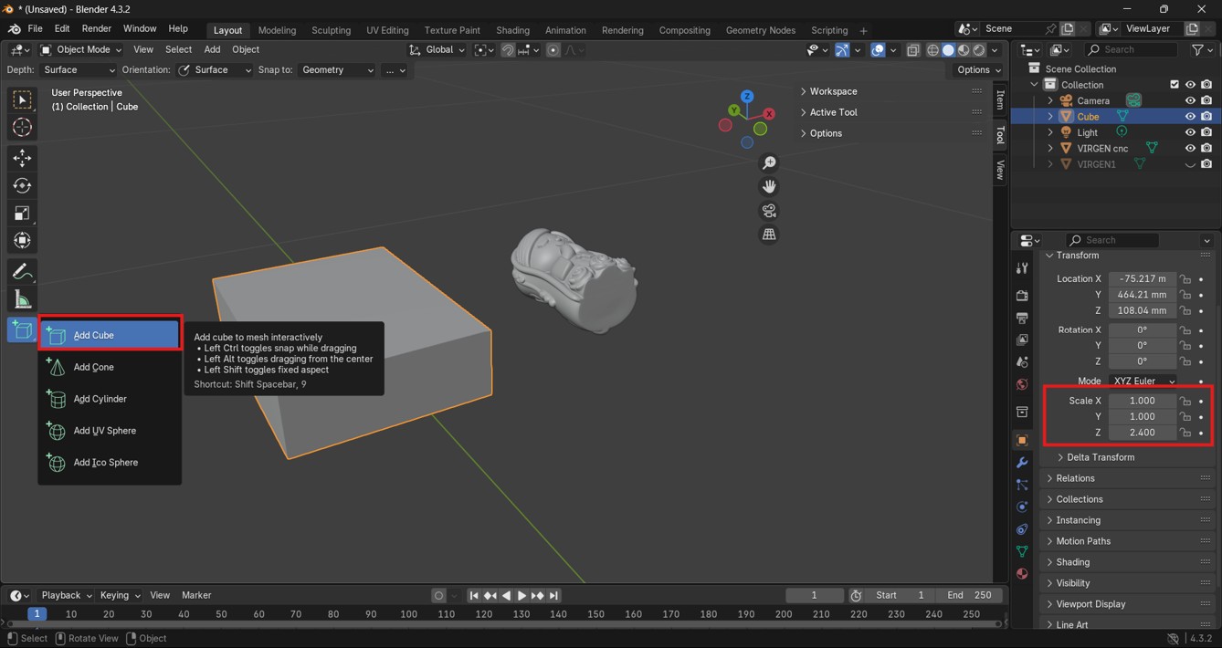
Img. 3: We drew a rectangular cube simulating the material to be machined.
Img. 4: We moved and centered our figure with the material.
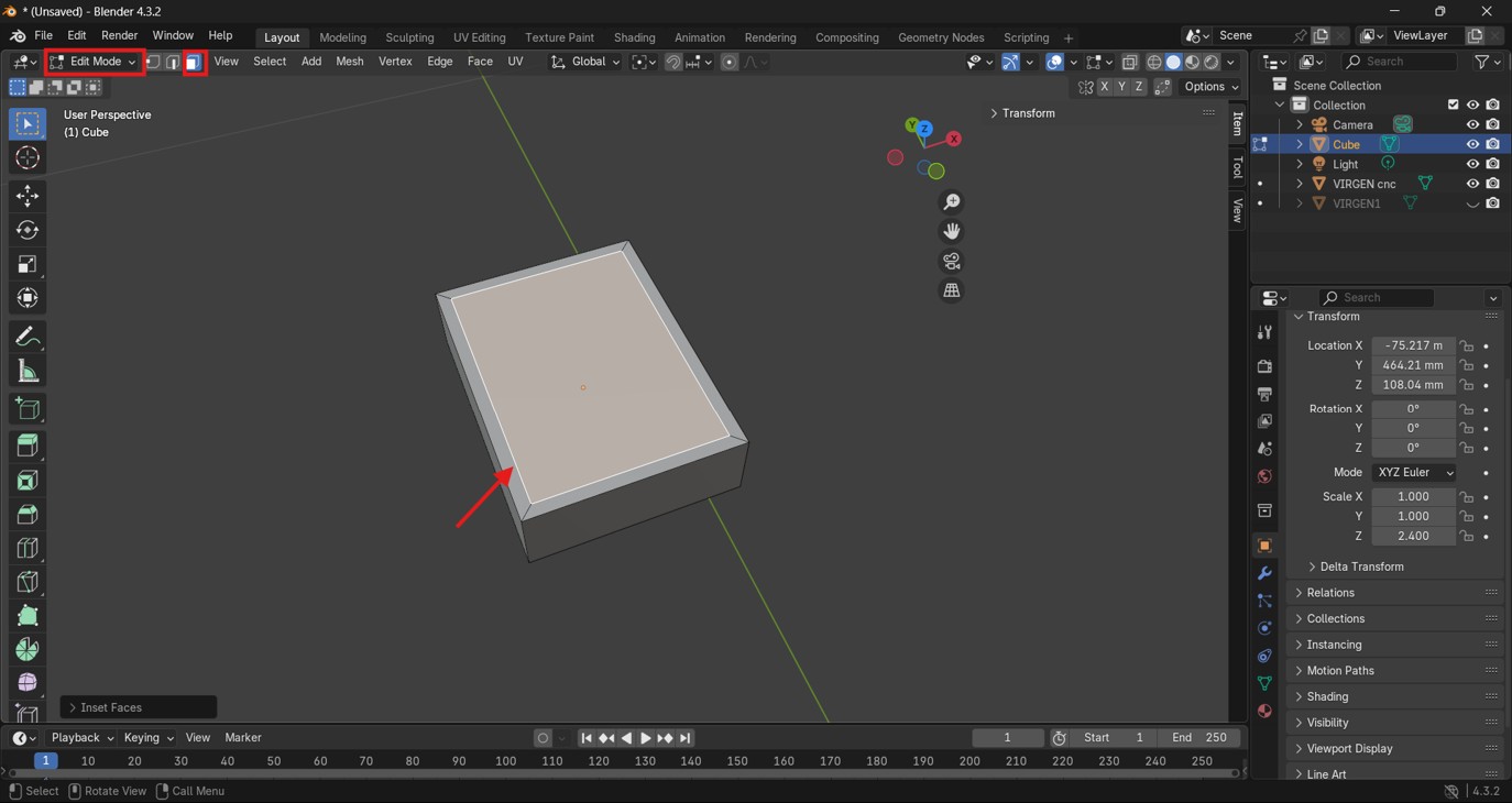
Img. 5: In Edit Mode, we selected the top face and used the “I” key to make an inward offset.
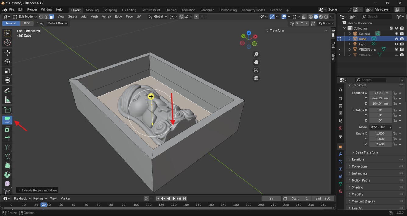
Img. 6: With the Extrude command, we subtracted the block almost halfway down the figure.
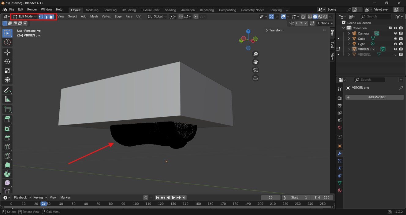
Img. 7: In Edit Mode, we deleted the excess below the figure.
Img. 8: We exported the mold in .OBJ or .STL format for machining in Aspire.
Machining with Aspire 10.5
- We created a new file and configured it with the measurements of the material to be used.
- In the Modeling tab, we searched for the “Import 3D model” option.
- We oriented and scaled our mold with the material to be used and clicked “Apply” and then “Accept”.
- We verified the imported 3D mold.
- We chose the “3D Roughing Toolpath” option to give the mold the first rough machining.
- We configured the tool by clicking “Select”. It should be noted that we used a 3.175 compression bit because it was the one available. We set the following parameters: RPM: 15000, Feedrate: 2500 mm/min, Pass Depth: 2.5 mm, Rest Machining = 40%, then clicked select, left the indicated configuration, and clicked “Calculate”.
- Before that, we drew a “curved polyline” in the “2D View” tab around only the Virgin contour in order to machine only the finishing of this area.
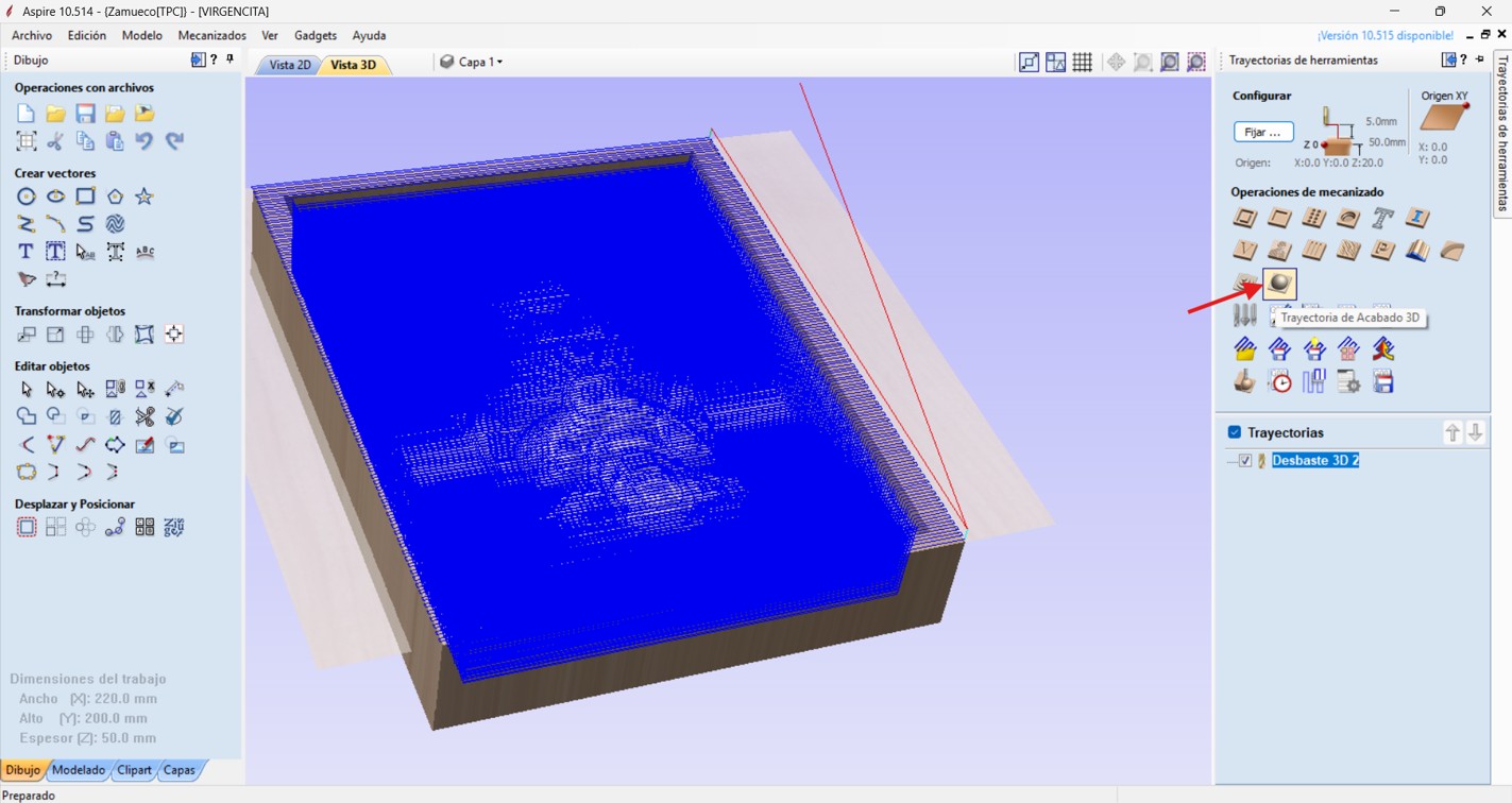
- We then chose the “3D Finishing Toolpath” option.
- We configured the tool by clicking “Select”. It should be noted that we used a 0.5 mm conical ball nose bit, 6 mm in diameter, and set the following parameters: RPM: 14000, Feedrate: 3000 mm/min, Pass Depth: 0.2 mm, Rest Machining = 10%. Finally, we clicked select, left the indicated configuration, selected the vector of the Virgin, and clicked “Calculate”.
- We verified by simulating the toolpaths.
- We saved the toolpaths to machine them on the CNC, saving them independently in .nc format.
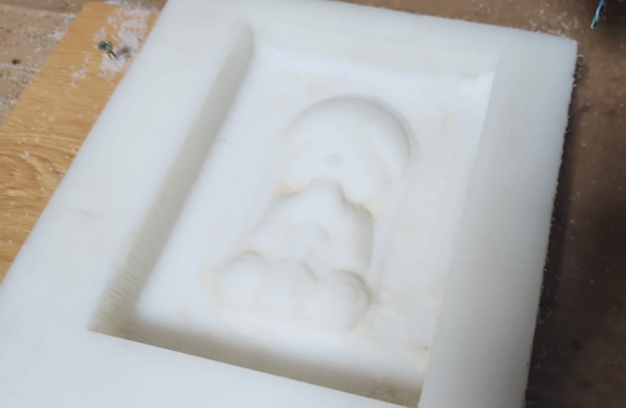
- We positioned our material, in this case a 5 cm thick POLYETHYLENE block, opened our file in NcStudio, and sent the first roughing machining.
- Once roughing was finished, we continued with the 3D finishing. For this, we changed to the ball nose bit, located the Z, and started machining.
- Finally, we sanded it finely with 1000 grit sandpaper.
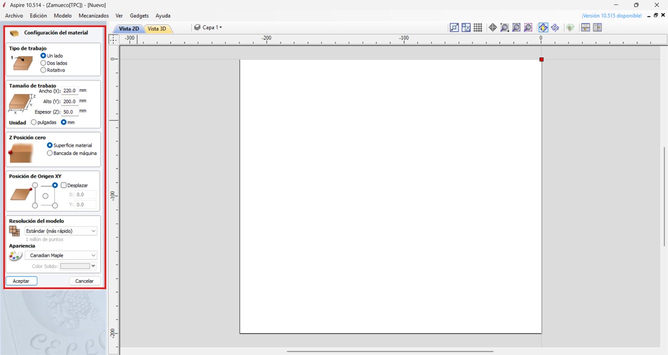
Img. 9: New file configured with the material measurements.
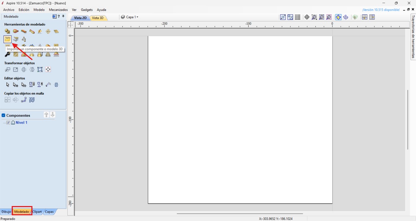
Img. 10: Importing the 3D model in Aspire.
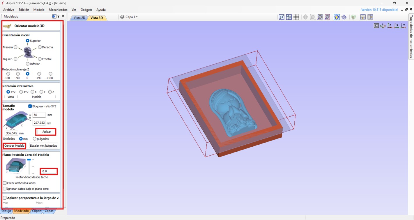
Img. 11: Orientation and scaling of the mold with the working material.
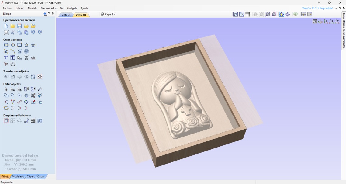
Img. 12: Imported 3D mold verification.
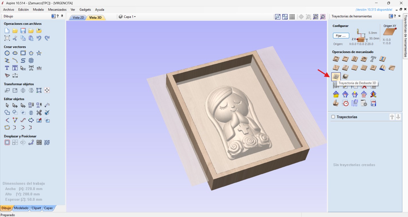
Img. 13: 3D roughing toolpath selection.
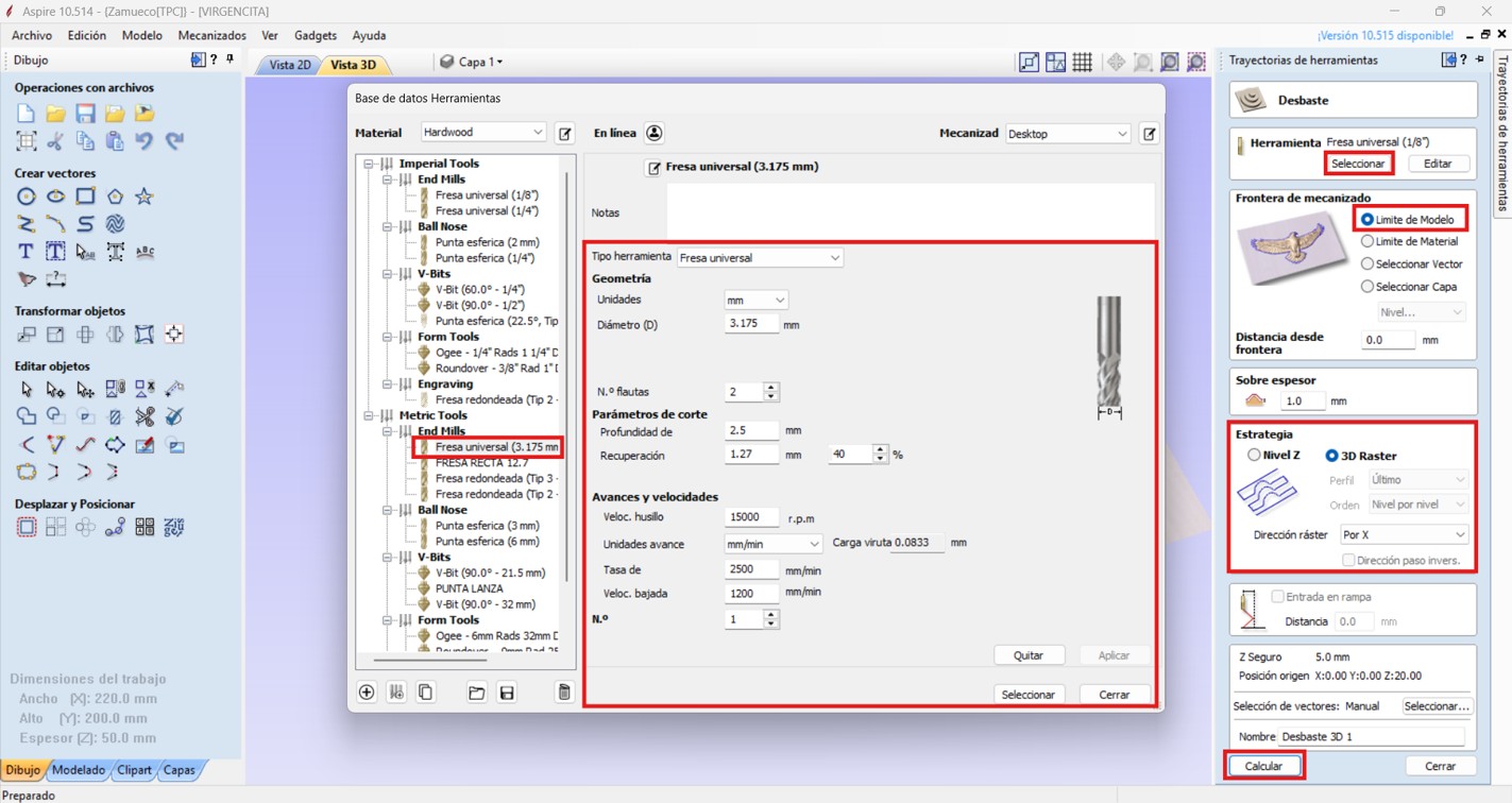
Img. 14: Roughing tool configuration.
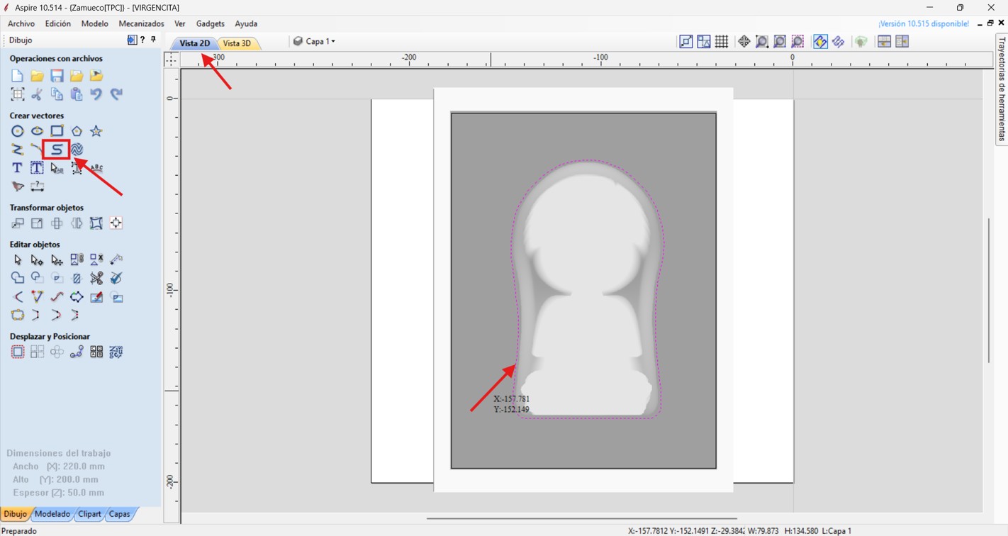
Img. 15: Curved polyline drawn to machine only the finishing area.
Img. 16: 3D finishing toolpath selection.
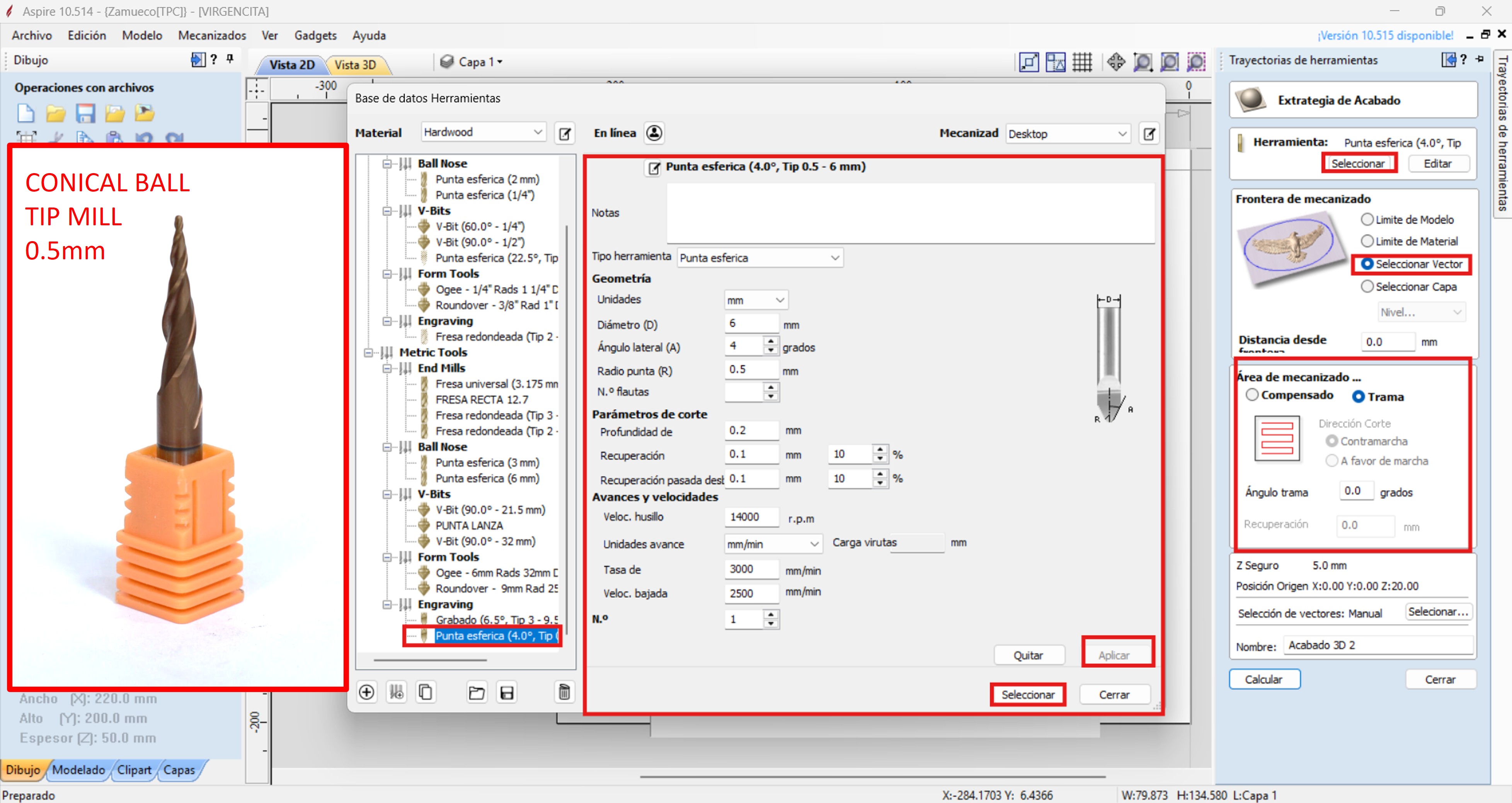
Img. 17: Finishing tool configuration.
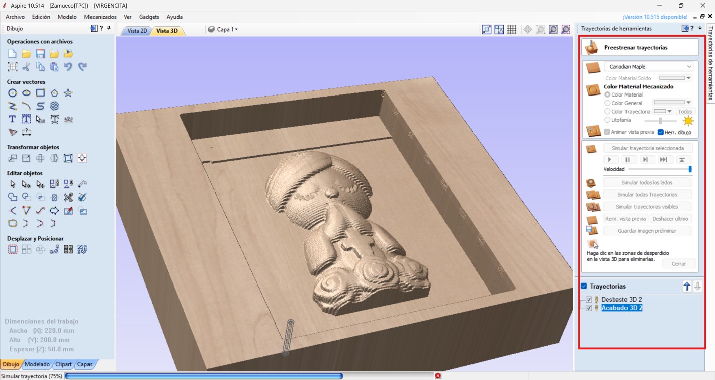
Img. 18: Toolpath simulation verification.
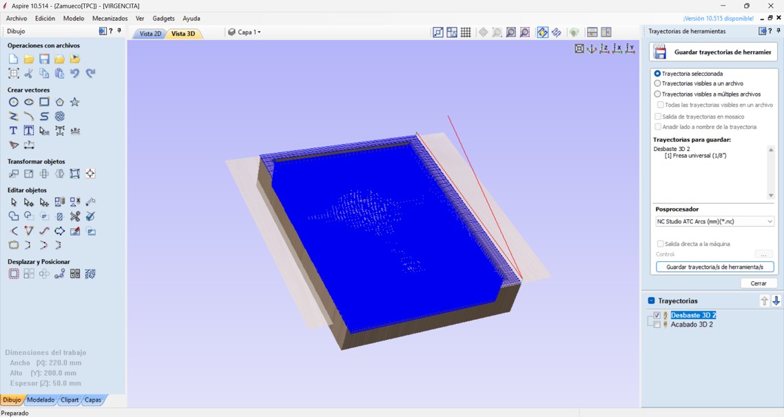
Img. 19: Toolpaths saved independently in .nc format.
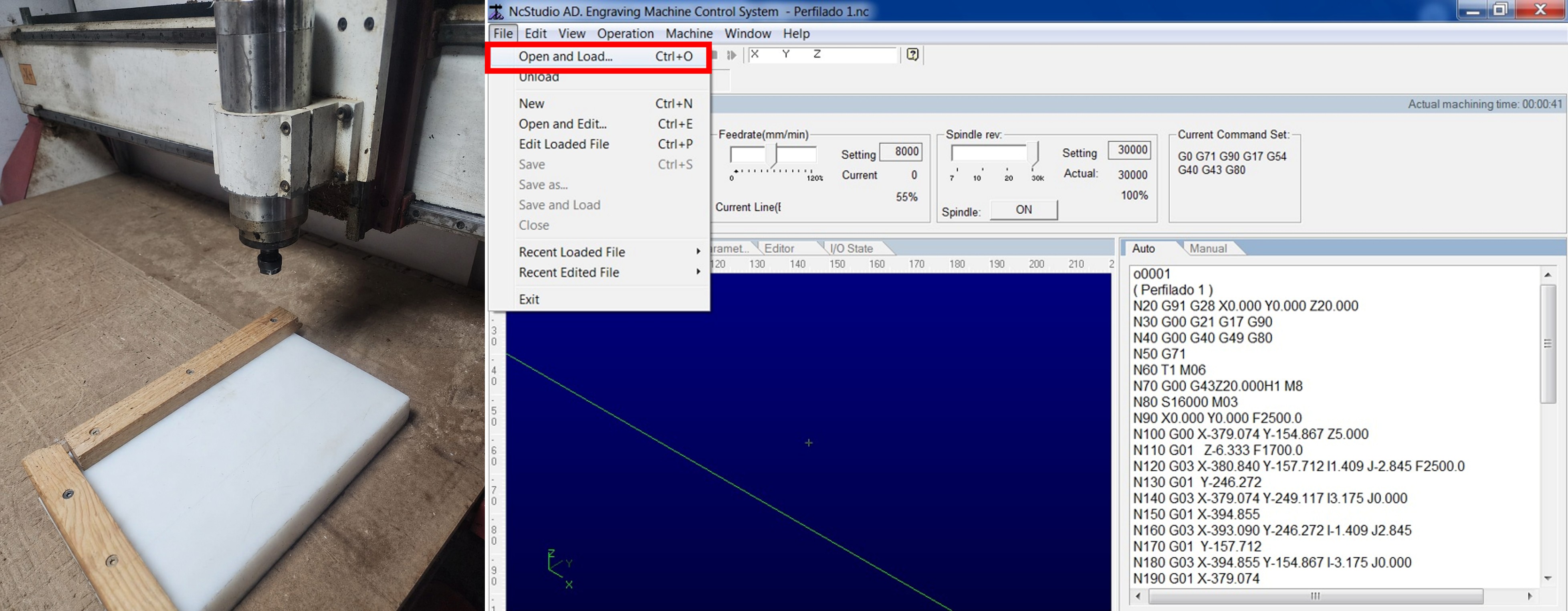
Img. 20: Polyethylene block positioned and roughing sent from NcStudio.
Img. 21: Fine sanding with 1000 grit sandpaper.
Printing Molds
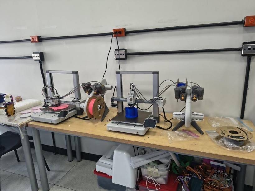
For the 3D printed mold, a Bambu Lab printer was used. To make the piece look as smooth as possible, we made two types of printing: lying down and standing up. A 5% infill with a gyroid pattern was used.
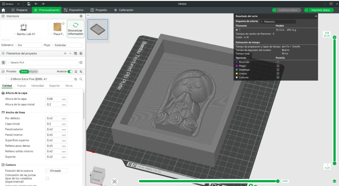
Img. 21.1: Lying-down printing of the mold.
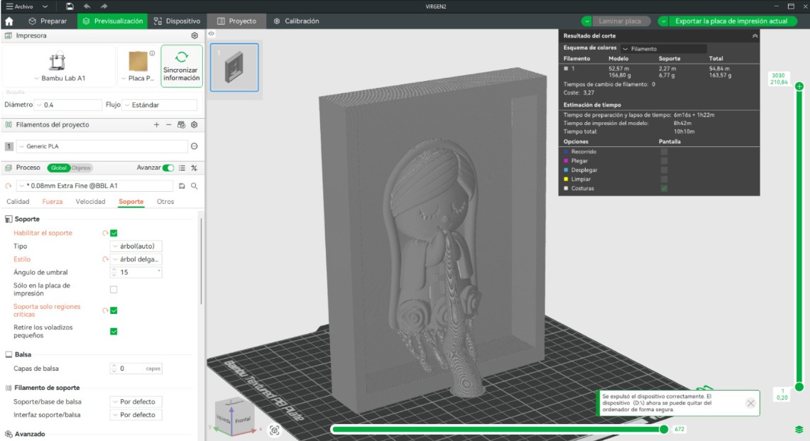
Img. 21.2: Standing-up printing of the mold.
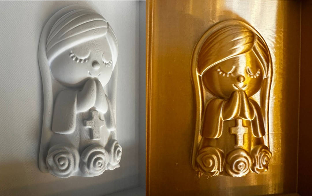
Img. 21.3: Result of the lying-down print on the left and standing-up print on the right; apparently, the standing-up print had a better finish, although the box had problems.
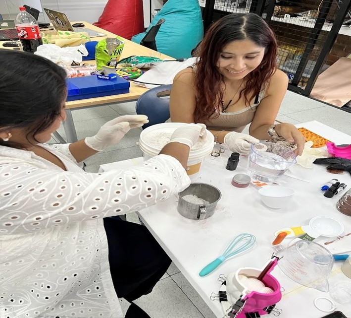
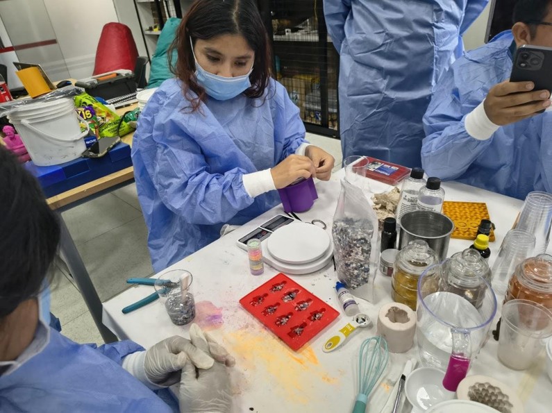
Review of Safety Data Sheets and Test Casts
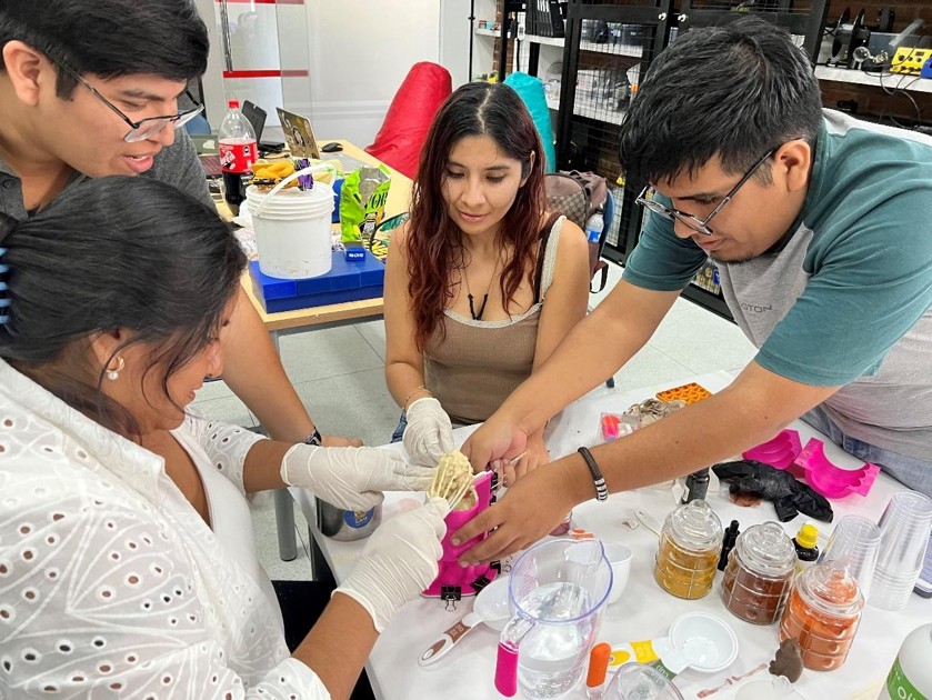
During the second part, on Sunday, April 26, we reviewed the safety data sheets of the molding materials and made and compared test molds with each of them.
1) Silicone RTV Mold Fabrication – Group Work
Process Description
As part of the group work, a silicone mold was developed using a rigid master fabricated through CNC machining. The mold geometry corresponds to a cavity with positive relief features, designed to accurately reproduce fine details and variations in depth in the final casted piece.
Due to the level of detail required, special attention was given to surface preparation, pouring, and curing stages to ensure high-fidelity geometric reproduction.
Rigid Mold Preparation
Before casting, the CNC-machined master was thoroughly cleaned to remove dust, residues, and any surface contaminants that could affect the final result.
Unlike FDM fabrication, CNC machining provided a significantly smoother and more continuous surface finish. However, minor toolpath marks were still present, so the surface was inspected to ensure it met the required quality for molding.
A liquid release agent was then applied evenly across the entire cavity, paying special attention to detailed and recessed areas. This layer prevents adhesion between the silicone and the master, allowing for safe and clean demolding.
Img. 22: Rigid mold preparation and release agent application.
Materials Used
The mold was produced using RTV silicone F-20 Plus from Silicon Perú, along with its corresponding catalyst.
- Type: General-purpose RTV silicone
- Application: Casting mold fabrication
- Mixing ratio: 3% catalyst by weight
This silicone has medium viscosity, allowing it to flow into detailed geometries, and medium hardness, providing enough flexibility for demolding without compromising structural stability.
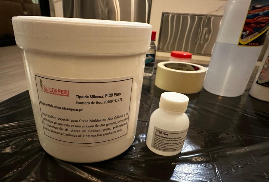
Img. 23: RTV silicone F-20 Plus and catalyst.
Mixing Process
The silicone was manually mixed with the catalyst following the specified ratio. Care was taken to achieve a homogeneous mixture to ensure uniform curing throughout the material.
During this process, air incorporation was identified as an inherent limitation of manual mixing, so additional measures were taken during pouring to minimize bubble formation.
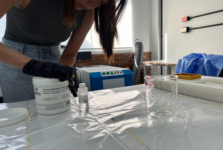
Img. 24: Manual mixing process.
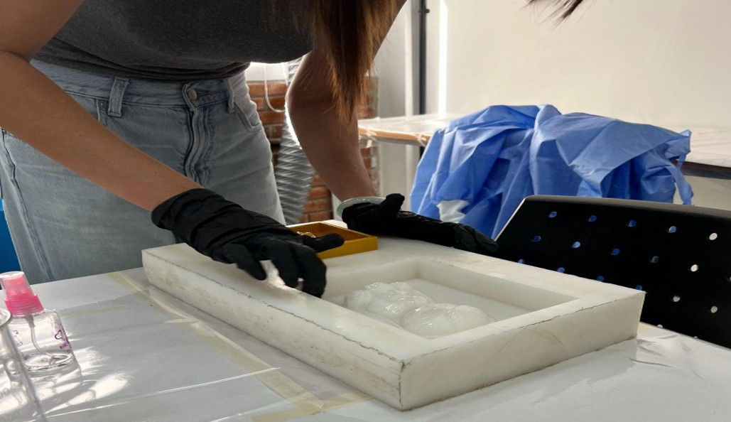
Casting Process
The silicone was poured slowly and in a controlled manner, starting from a single point to allow the material to flow progressively into the cavity. This technique helps reduce air entrapment in deeper regions.
Additionally, the mold was gently tapped against the working surface to help release trapped air bubbles. Although this method improves results, it has limitations compared to vacuum degassing.
The cavity was filled completely to ensure full reproduction of all geometric details.
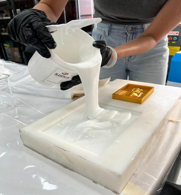
Img. 25: Silicone casting process.
Curing
After pouring, the silicone was left to cure at room temperature for the recommended time specified by the manufacturer. During this stage, the mold was not manipulated in order to avoid deformation or defects in the final structure.
Demolding and Evaluation
Once fully cured, the silicone mold was carefully demolded. The release agent performed effectively, allowing separation without damage to either the mold or the master.
The resulting mold showed a high level of detail reproduction, with clean edges and consistent surface quality across the entire geometry.
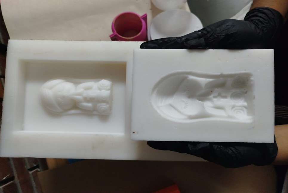
Img. 26: Final silicone mold after demolding.
Process Conclusion
The use of a CNC-machined master significantly improved the final mold quality compared to additive manufacturing alternatives. The smoother initial surface reduced the need for post-processing and resulted in better surface finish in the silicone mold.
Overall, the process was successful:
- The geometry was accurately reproduced
- Surface quality was consistent and clean
- No major defects or deformation were observed
- Minor air bubbles were present but did not affect functionality
The final mold is suitable for casting applications requiring good detail resolution and structural reliability.
2) Bio Silicone – Regen
As part of the group assignment, Regen Bio was used, a digital biomaterials platform linked to REGEN, an initiative publicly presented as a Fab Lab Perú project aimed at promoting a regenerative economy in the Amazon. REGEN was also recognized as one of the winning projects of the Biodiversity Small Funds Initiative, promoted by the Global Plastic Action Partnership (GPAP) within the framework of the World Economic Forum and announced during the UN Ocean Conference 2025. In this context, the project was highlighted for its work with Indigenous communities in Peru in the creation of biodegradable alternatives from natural materials. In this activity, the platform was used as support to define the properties, ingredients, and preparation conditions of the bio-silicone evaluated in the group practice.
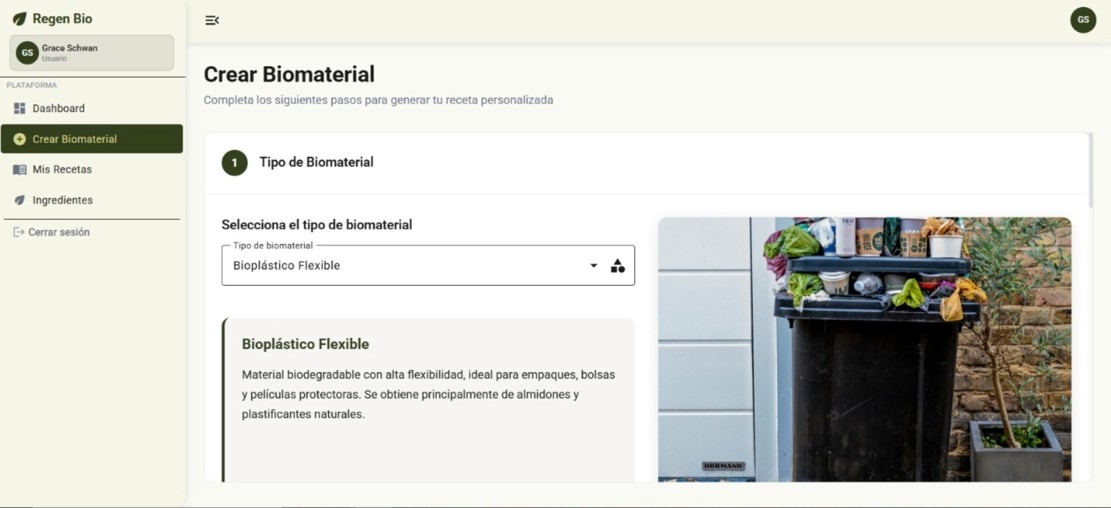
Img. 27: Regen Bio platform.
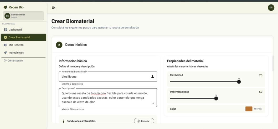
Img. 28: Bio-silicone recipe reference.
Biomaterial Test: Bio-silicone
As part of the group assignment, a molding test was carried out using bio-silicone made from accessible ingredients, following a biomaterial recipe obtained from a biomaterials platform. The objective of this test was to observe the behavior of the material during its preparation, pouring, and solidification, as well as to evaluate its surface finish and its response when poured into a 3D printed mold.
For this test, a group mold made by 3D printing was used, with the shape of a little Virgin with flowers. The mixture showed good general behavior and made it possible to obtain a piece with a very satisfactory visual result.
Ingredients Used
- 520 g of gelatin sheets
- 500 ml of water
- 50 ml of glycerin
- 15 drops of clove essence
Properties of the Ingredients Used
| Ingredient | Quantity | Function in the Mixture | Observed Characteristics | Handling Considerations |
| Gelatin sheets | 520 g | Main base of the biomaterial; provides body and consistency | When heated, it softens and allows a homogeneous mixture to form; when cooled, it acquires flexible consistency | It must be heated in a controlled way to avoid sticking to the bottom or burning |
| Water | 500 ml | Dissolution and binding medium for the ingredients | Facilitates hydration of the gelatin and helps obtain a uniform mixture | It must be incorporated in the correct proportion to avoid a mixture that is too liquid or too thick |
| Glycerin | 50 ml | Plasticizer; provides flexibility | Improves elasticity of the biomaterial and prevents it from becoming too rigid or brittle | It must be mixed well to achieve a uniform texture |
| Clove essence | 15 drops | Aromatic additive and natural preservative | Provides a pleasant smell and helps delay the appearance of fungi | Used in small amounts; incorporated at the end or during controlled mixing |
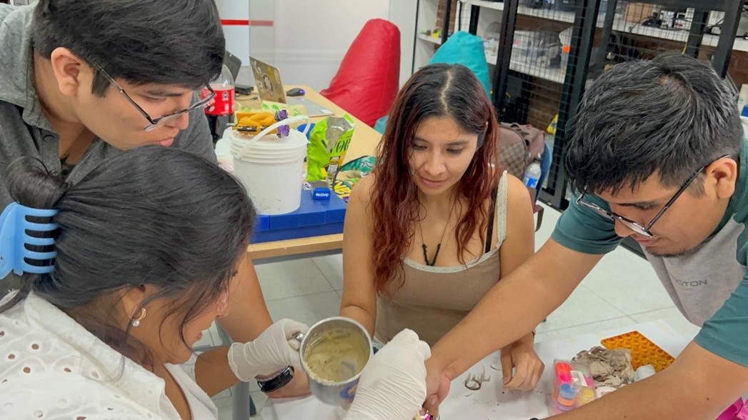
Preparation Procedure
Before starting, we first measured with water inside the mold to know how much material we would use, then we prepared the measures in percentage for this bio-silicone.
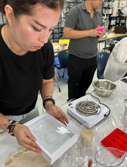
Img. 29: Measuring the amount of material using water inside the mold.
To prepare the bio-silicone, we placed all the ingredients in a metal bowl and heated them in order to integrate them uniformly. The mixture was worked at approximately 70 °C, ensuring that the components melted and progressively joined until forming a homogeneous material.
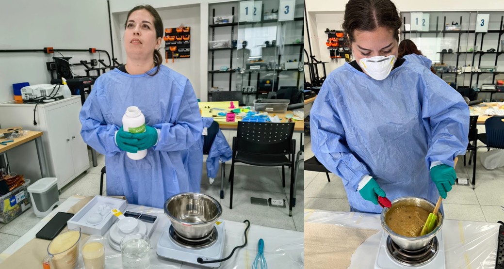
Img. 30: Heating and integrating the bio-silicone ingredients.
As part of the pre-process, before pouring the bio-silicone into the 3D printed mold of the little Virgin with flowers, a layer of petroleum jelly was applied on the internal surface of the mold. This step was carried out to facilitate demolding once the piece solidified, preventing the biomaterial from sticking to the mold and reducing the risk of damaging both the final piece and the mold during extraction.
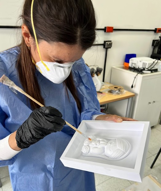
Img. 31: Petroleum jelly applied to facilitate demolding.
Once the mixture reached an adequate consistency, it was carefully poured into the 3D printed mold corresponding to the group test, which had the shape of a little Virgin with flowers. Afterwards, the material was left to rest so that it could begin its solidification process inside the mold.
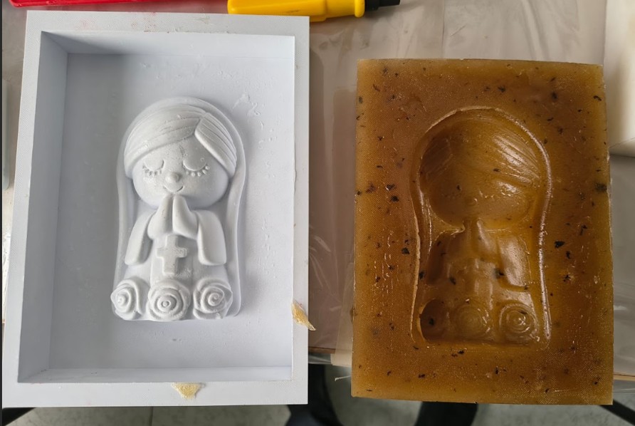
Img. 32: Bio-silicone poured into the 3D printed mold.
Observations of the Material During the Test
During preparation, the bio-silicone showed a good ability to integrate its components. The mixture reached a uniform texture and could be poured without significant difficulty into the mold. In addition, the material adapted well to the geometry of the model, allowing the shape to be reproduced satisfactorily.
The final result was very positive, since the obtained piece had a pleasant appearance and an attractive visual finish. Despite the problems that occurred during cooking, the biomaterial could be used without appreciably altering its composition, and the result was successful.
Problems Presented and How We Solved Them
During this test, an inconvenience occurred during the heating stage. The mixture stuck a little to the bottom of the container, mainly because the metal container used was smaller than necessary and, in addition, too much heat was applied at the beginning. This caused part of the material to have more contact with the hot bottom before fully integrating.
To solve this problem, the temperature was controlled better and mixing continued carefully to prevent the material from continuing to stick or burn. Fortunately, the problem did not significantly affect the final mixture, since the material continued melting and maintained its general properties. Thanks to this, the bio-silicone could be used correctly and the final piece obtained a very good result.
Reflection on the Test
This test allowed me to understand that, in biomaterials, not only the recipe matters, but also the heating conditions, the appropriate container size, and temperature control throughout the entire process. I also learned that small errors at the beginning, such as excess heat, can be corrected if action is taken in time and the mixture continues to be worked carefully.
In conclusion, bio-silicone was an interesting material to experiment with this week, since it allowed us to explore a biomaterial alternative applied to molding and casting, with a satisfactory final result both in appearance and behavior inside the mold.
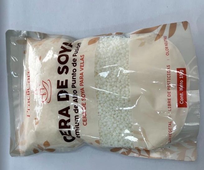
3) Soy Wax
For this assignment, I worked with soy wax, a 100% vegetal and refined material commonly used for candle making. This material comes in small pellets, which makes it easier to handle and melt uniformly. One of its main advantages is its clean finish, neutral odor, and safe handling compared to other casting materials. According to the specifications, its melting point ranges between 60°C and 65°C, making it suitable for controlled casting processes.
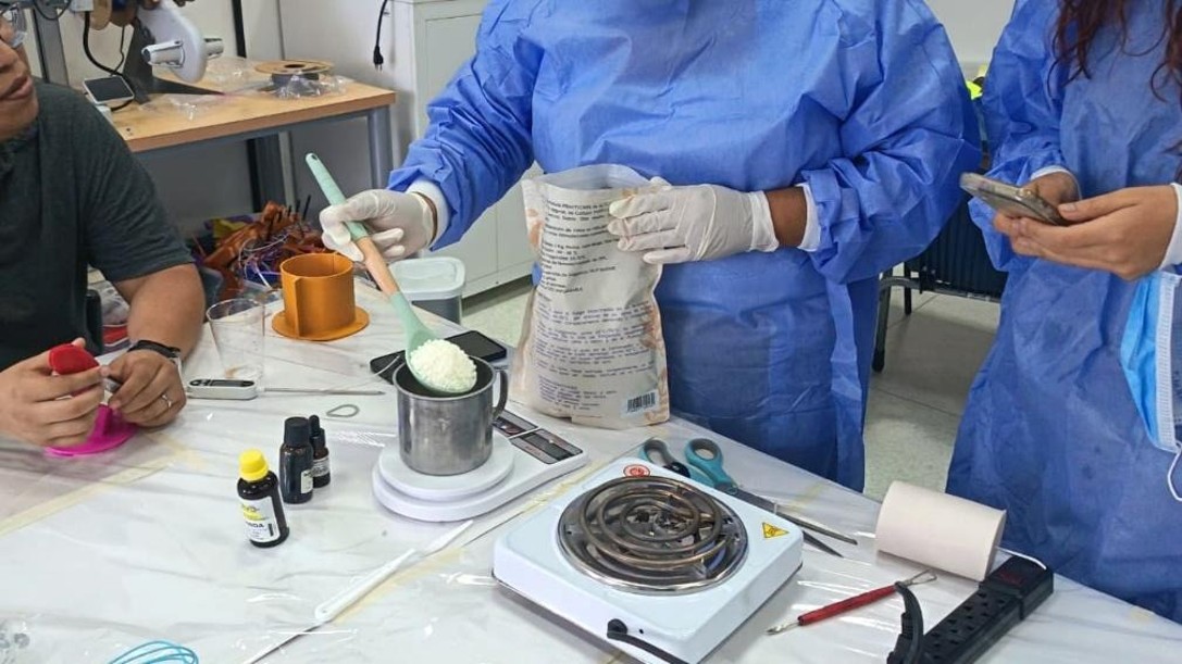
Melting Process (Double Boiler Method)
Img. 33: Soy wax melting process using the double boiler method.
To melt the soy wax, I used the double boiler method (bain-marie), which allows indirect and controlled heating. First, I placed water in a lower container and heated it using a small stove. Then, I placed another container on top containing the soy wax pellets. This method prevents direct contact with heat, reducing the risk of burning or degrading the material.
I continuously monitored the temperature during the process until the wax reached approximately 65°C, ensuring it melted completely into a transparent liquid. This step is critical to achieve a uniform consistency and avoid imperfections in the final casting.
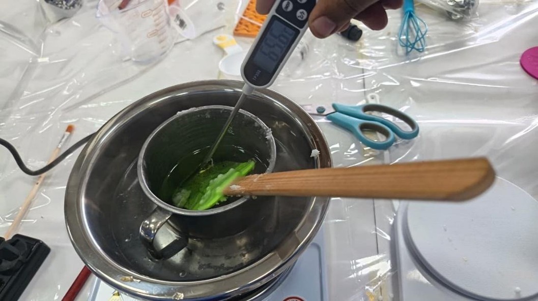
Temperature Control and Safety
Img. 34: Temperature control during wax melting.
Maintaining the correct temperature was essential during the melting process. I ensured that the wax did not exceed the recommended range to prevent overheating. Working with controlled heat also improved safety, since soy wax is flammable if exposed to excessive temperatures. Additionally, I worked in a ventilated space and handled the containers carefully to avoid spills or burns.
Preparation for Casting
Img. 35: Mold preparation before casting soy wax.
Once the wax reached the proper liquid state, it was ready to be poured into the mold. Before casting, I made sure that the mold was clean and properly positioned to avoid misalignment or leakage. The fluidity of the wax at this temperature allowed it to fill the mold easily, capturing the shape with good detail.
Cooling and Final Result
After pouring the melted wax into the mold, I allowed it to cool down at room temperature in a stable and ventilated environment. The cooling process is important to ensure that the material solidifies evenly and maintains its final shape without deformation. Once completely cooled, the piece was removed from the mold, resulting in a clean and well-defined cast.
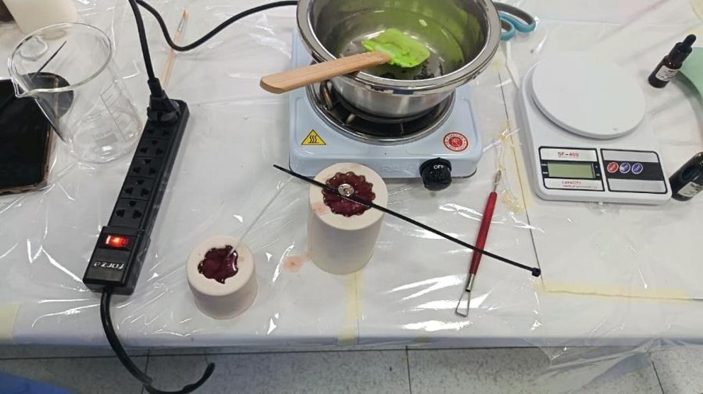
Img. 36: Final soy wax cast result.
4) Lavender Soap
As part of the casting tests, soap was prepared using glycerin soap base through the double boiler method. For this, a metal container with hot water was used and, inside it, a glass beaker was placed, where the soap base was added for indirect and controlled melting.
Img. 37: Glycerin soap base melted using a double boiler.
During the process, the soap base was worked at approximately 60 °C, an appropriate temperature to favor melting without overheating the material. Once the base was melted and a homogeneous mixture was obtained, two variants were prepared. In the first, coffee grounds were added, in order to provide texture and a more artisanal finish. In the second, lavender essential oil was incorporated, seeking to provide aroma and generate a variant with a more uniform appearance.
Img. 38: Preparation of soap variants with coffee grounds and lavender essential oil.
Finally, both mixtures were poured into molds and left to rest until solidification. This procedure made it possible to obtain pieces with different characteristics, both in texture and aroma, and showed that the double boiler method is suitable for melting this material gradually and safely.
Img. 39: Final soap pieces after solidification.
Properties of the Ingredients Used in the Soap
| Ingredient | Function in the Mixture | Observed Properties | Contribution to the Final Result | Handling Considerations |
|---|
| Glycerin soap base | Base material for casting | Melts easily with indirect heat, has good fluidity, and solidifies quickly | Allows pieces with good shape and uniform finish | Must be heated in a controlled way to avoid overheating |
| Coffee grounds | Natural solid additive | Provides texture and artisanal appearance | Generates a more textured surface and a more rustic visual finish | Must be mixed uniformly before pouring |
| Lavender essential oil | Aromatic additive | Provides a pleasant aroma and a sensory variant | Improves the final experience of the piece and maintains a more uniform appearance | Must be added once the base is melted |
| Double boiler water | Indirect heating medium | Allows soap to melt without direct contact with the heat source | Favors gradual and controlled heating | It is important to control the temperature throughout the process |
Process Observations
In this test, no significant inconveniences occurred during mixture preparation or pouring. Therefore, instead of recording problems, the main aspects controlled during the process and the results obtained are presented.
Process Control and Results
| Evaluated Aspect | Observed Result | Action Applied |
|---|
| Soap base melting | The base melted homogeneously | Double boiler was used to control heating |
| Working temperature | The mixture remained stable around 60 °C | Direct heating was avoided |
| Incorporation of coffee grounds | It integrated adequately into the mixture | It was mixed gently before pouring |
| Incorporation of lavender essential oil | The aroma remained in the final piece | It was added once the base was melted |
| Pouring into molds | The material flowed correctly inside the mold | It was poured carefully and progressively |
| Solidification | The pieces solidified adequately | They were left to rest for the necessary time |
| Demolding | The pieces were removed without difficulty | An appropriate mold was used for the test |
Test Result
The test made it possible to verify that glycerin soap base is a suitable material for small-scale casting processes, since it presents controlled melting, good pouring capacity, and fast solidification. Likewise, it was observed that the incorporation of coffee grounds and lavender essential oil modifies the final characteristics of the piece, generating variants with different textures, finishes, and sensory properties.
5) Molding and Casting with Plaster
Hello! In this activity, I carried out the Molding and Casting process with plaster. I decided to work with plaster to obtain a solid and detailed piece. Below, I describe the step-by-step process, recipe style, of everything I did in the laboratory.
I. The Technical “Recipe”
To guarantee dimensional stability and an acceptable Rockwell hardness in the final piece, the following mixing parameters were established:
- Base ingredient: High-purity alpha-hemihydrate plaster (plaster for molds).
- Hydrating agent: Water.
- Mixing ratio (W/P ratio): 1 to 2 by weight (100 ml of water for every 200 g of plaster). For this practice, we used 150 ml of water and 300 g of plaster.
- Additives: Fast-dispersion natural pigment (turmeric) for aesthetic contrast and flow analysis.
- Matrices: Industrial-grade silicone molds (RTV-2) with Shore A 25 hardness.
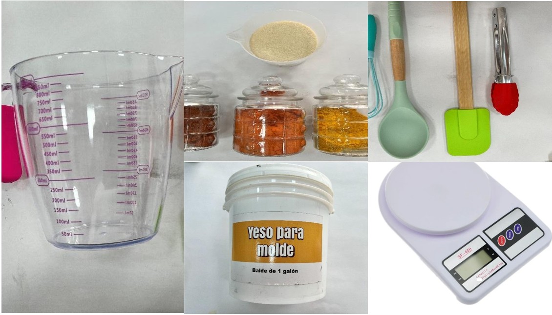
Img. 40: Materials for plaster casting.
Img. 41: Plaster mixing preparation.
II. Operating Protocol (Step-by-Step with Foundation)
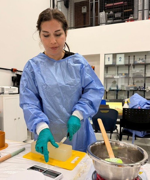
1. Safety and Biosecurity Management (PPE Protocol)
Before the intervention, physical barriers were implemented. The handling of mineral powders with micrometric granulometry requires respiratory protection to avoid silicosis or irritation of mucous membranes.
Img. 42: Safety protocol with gloves and mask.
In this phase, I verified the integrity of the molds. I used nitrile gloves and a surgical mask. Organization of the worktable is vital to avoid chemical accidents or contamination of the mixture.
2. Prototyping of the Master Geometry
The process does not begin with plaster, but in the digital environment. We used FDM (Fused Deposition Modeling) technology to manufacture the “negatives” and structural supports that would shape the silicone mold.
Img. 43: Master geometry prototype.
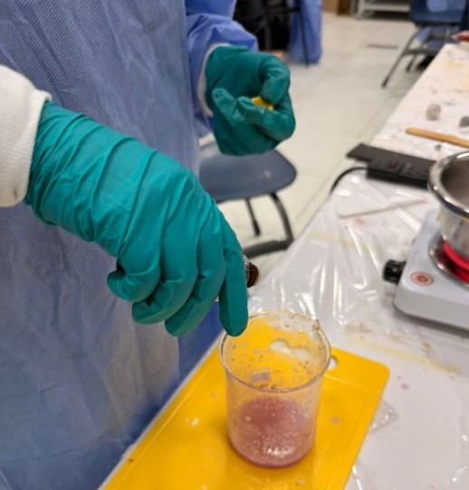
3. Mixture Preparation (Hydration and Homogenization)
The rain pouring technique was applied. The plaster was not thrown in as a block, but sprinkled over the water to avoid air encapsulation and the formation of lumps (dry cores).
- Weighing: Digital scale used for ±0.1 g precision.
- Rest: The plaster was allowed to absorb water by capillarity for 30 seconds.
- Agitation: Manual mechanical mixing with a blue stirrer, keeping the instrument at the bottom to minimize cavitation (introduction of bubbles).
Img. 44: Plaster hydration and homogenization process.
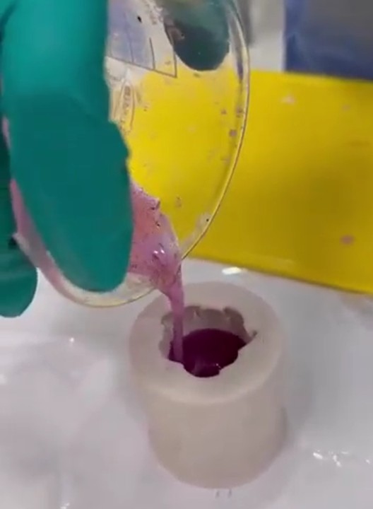
4. Casting Technique and Synchronized Work
Due to the hydrostatic pressure exerted by liquid plaster on the walls of the silicone mold (which is flexible), external support is required. Pouring must be laminar and constant.
Img. 45: Plaster casting technique.
5. Vibration, Setting, and Thermal Control
After filling, the mold was subjected to a series of mechanical impulses (tapping/vibration) to break the surface tension and release microbubbles trapped in the fine details.
Img. 46: Vibration and setting process.
III. Laboratory Management Conclusions
- Technical cleaning: Containers were washed before final hardening to avoid solid residues in future samples.
- Quality: The resulting piece had a silky texture, without surface porosity, validating the manual vibration method.
- Sustainability: Excess plaster was disposed of in dry waste containers, avoiding contamination of the Fab Lab drainage system.
II) Individual Assignment
For my individual work, I thought a lot about what type of mold to make. In the region where I live, a lot of cacao is produced, so there are several producers who make chocolate, and the big problem they have is having personalized molds. Because of the distance of our region, Madre de Dios, from the capital of Peru and the high transportation costs, it is difficult to find molds and the prices are very high. For this reason, I decided to make a mold for chocolates.
First, I reviewed the inventory of molding materials available in the Digital Fabrication Laboratory of IESTP Jorge Basadre Grohman. To my pleasant surprise, we had food-grade silicone, so I got to work with the delicious chocolates.
| Item | Material / Product | Type | Presentation | Reference Price | Main Use |
|---|
| 1 | White Cement for Mold | Powder | 1 gallon | S/ 45 – 65 | Rigid / decorative molds |
| 2 | Plaster for Mold | Powder | 1 gallon | S/ 25 – 40 | Quick test molds |
| 3 | OOMOO 25 | Tin-cure silicone | Kit A + B | S/ 180 – 260 | Flexible molds |
| 4 | F20 Plus Silicone with catalyst | Silicone | 1 kg | S/ 55/kg | General molding |
| 5 | Platinum Silicone (A and B) equal parts | Food / medical grade | 1 kg | S/ 79/kg | Chocolates / food |
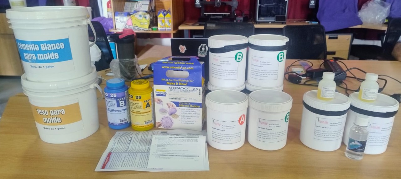
Img. 47: Molding materials.
Mold Design
Due to a failure in the voltage stabilizer of the FAB LAB laboratory, it was not possible to use the CNC machine during this week. Therefore, it was decided to adapt the fabrication process by using 3D printing as the main method for producing master molds.
This alternative made it possible to continue with the development of the week using the available tools, demonstrating adaptability to technical limitations while maintaining the digital fabrication approach.
The work focused on the design and 3D printing of molds for:
- Personalized chocolates
- Decorative candles
1: Chocolate Mold
1. Design in Fusion 360
For the design, I had many crazy ideas for shapes and designs, but I opted for a simple one because I did not know how well a mold using 3D printing would turn out. I decided to design a flower-shaped mold to make three chocolates at the same time.
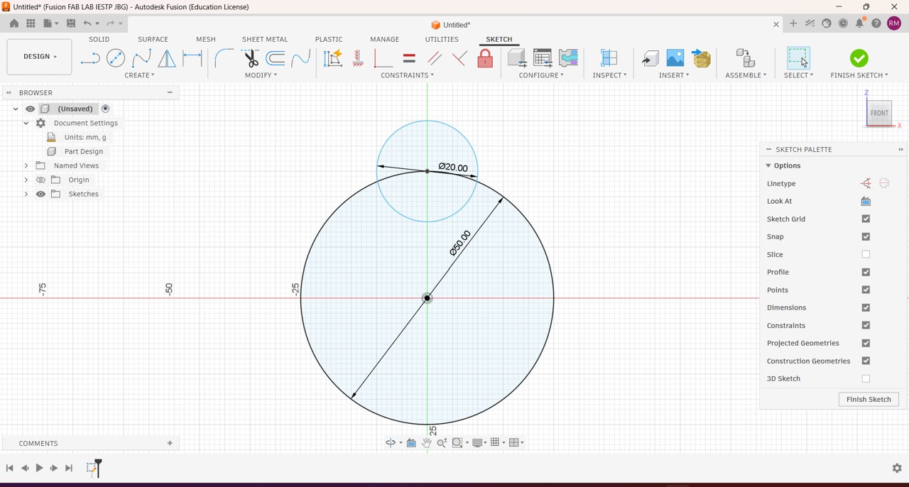
Img. 48: I started with the design of a 5 cm diameter circle; for the petals I drew another 2 cm diameter circle.
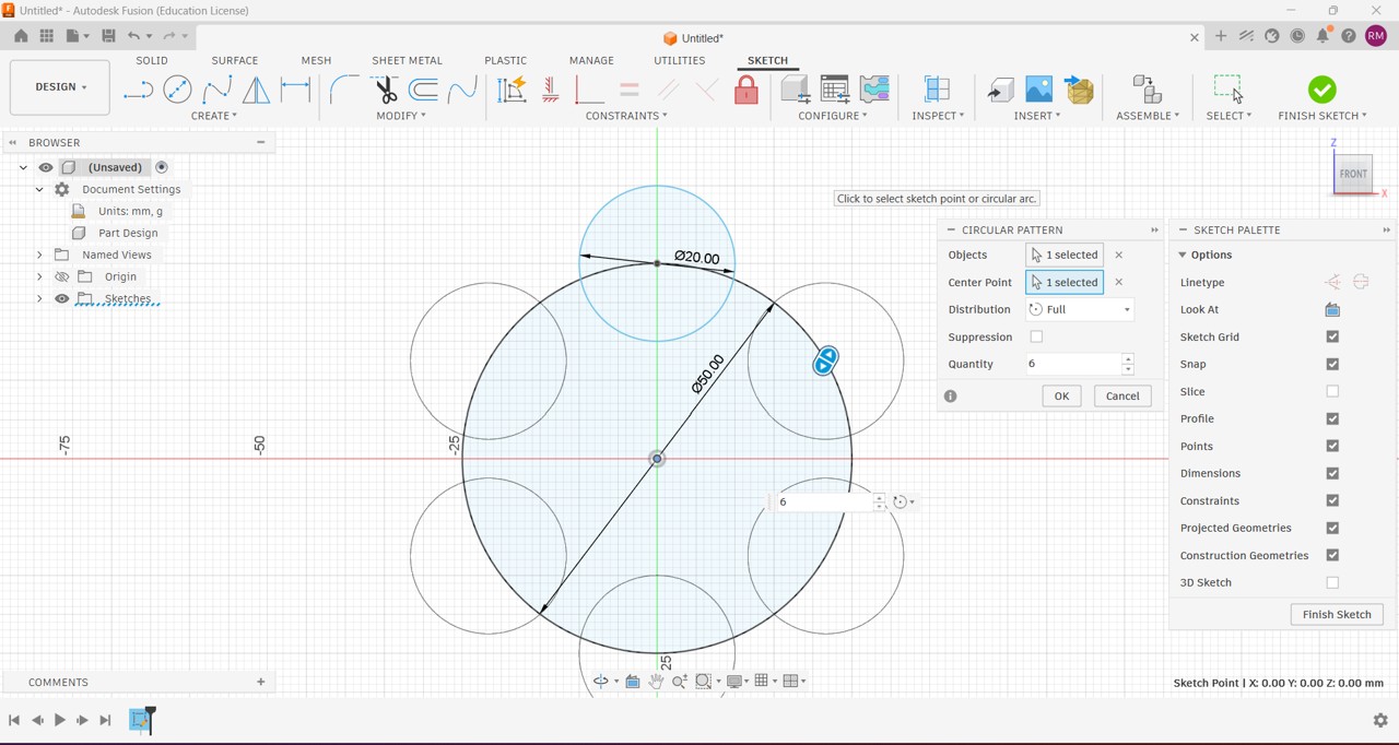
Img. 49: Then I used circular pattern to make my flower have 6 symmetrical and well-distributed petals.
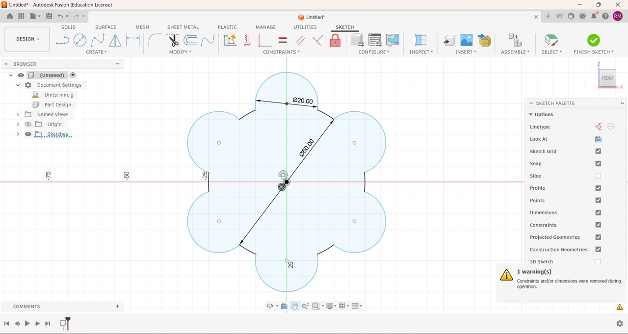
Img. 50: By pressing the T key plus the left mouse button, I deleted all the lines I did not need from my design, leaving the outline clean.
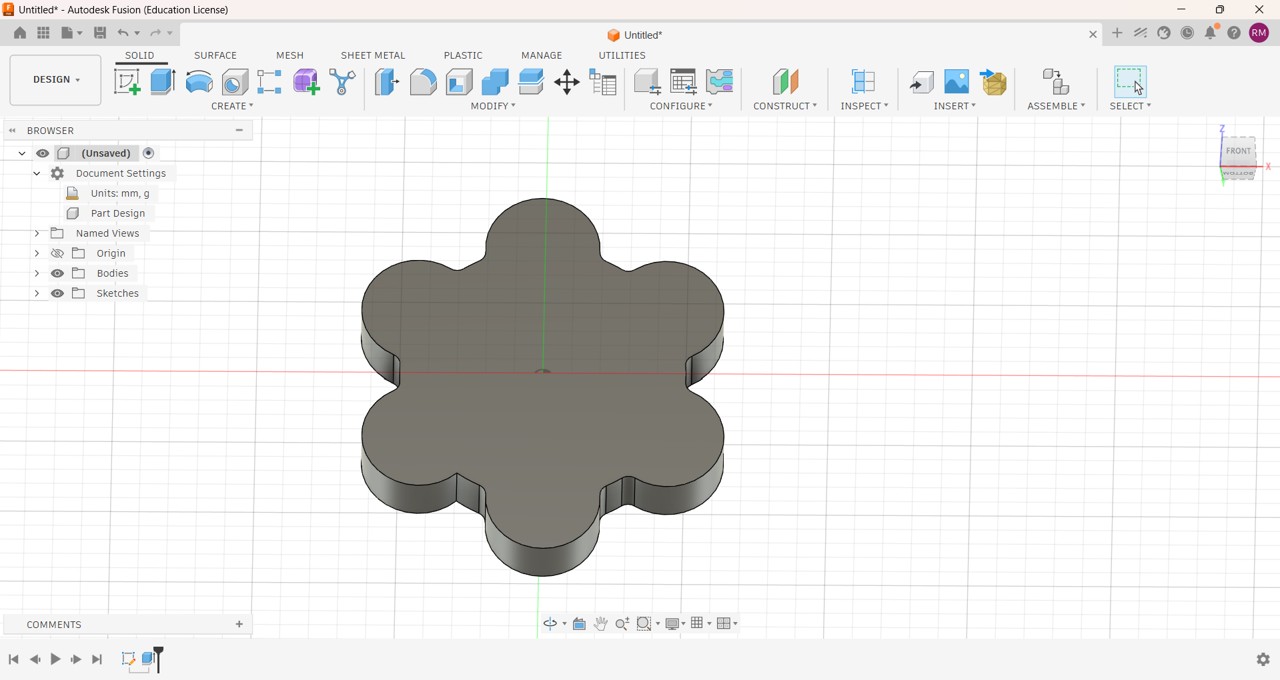
Img. 51: Then I finished the sketch and extruded the design, giving it a thickness of 1.5 cm.
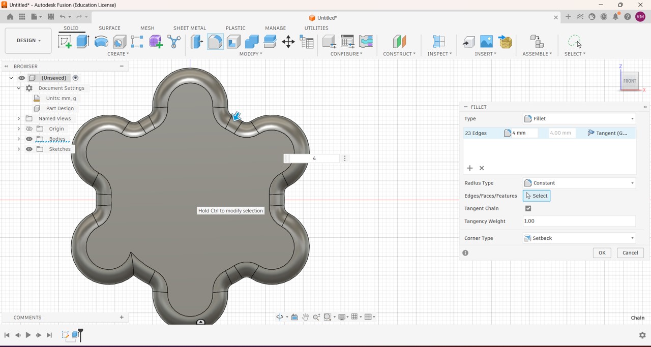
Img. 52: I rounded the edge using a 4 mm Fillet, constant radius type.
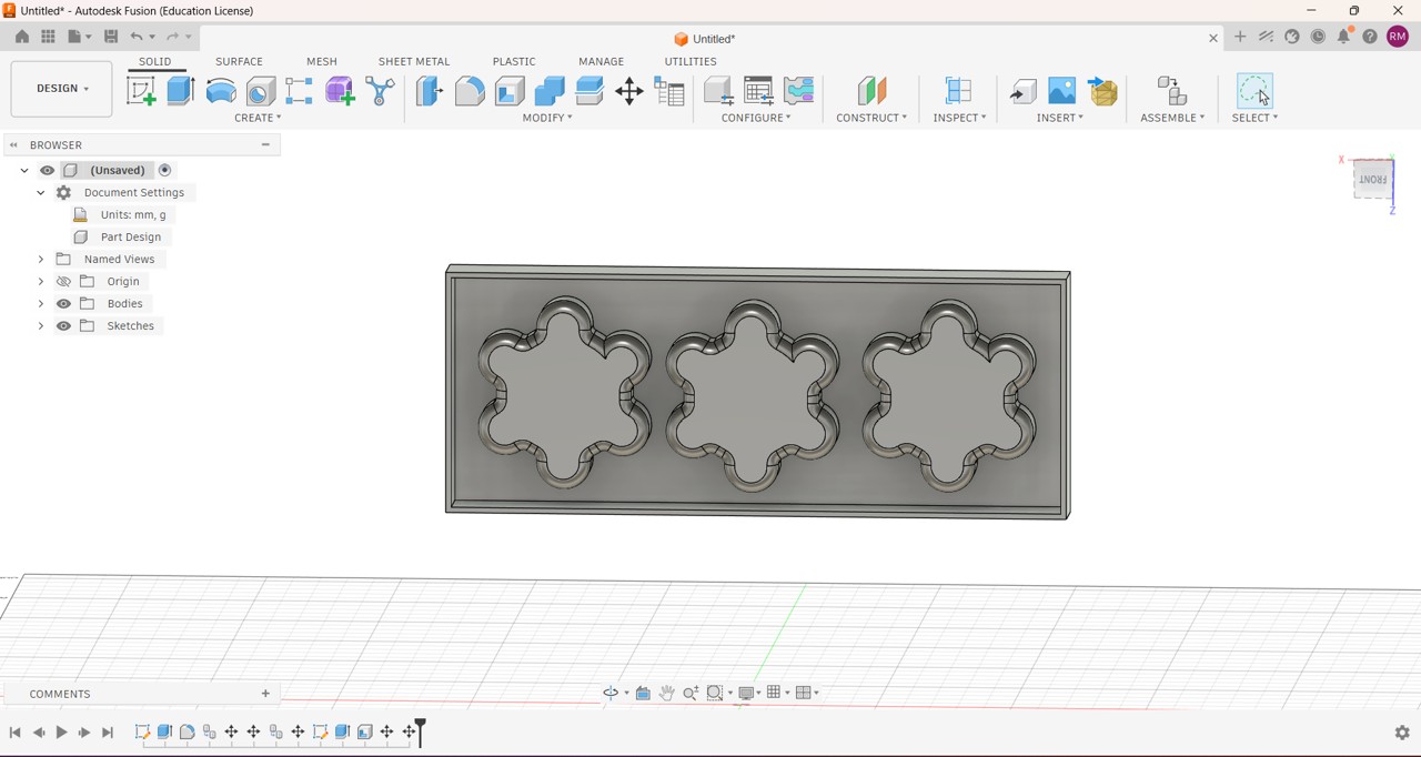
Img. 53: Then I designed a rectangle of 20 x 7.3 cm, extruded it to have 1.8 cm depth, created a cavity to have a 2 mm wall thickness, and finally made 2 more copies of my flower design to have three chocolates at the same time.
2. 3D Printing of the Master Mold
For 3D printing, I used PLA and a Creality K1C printer.
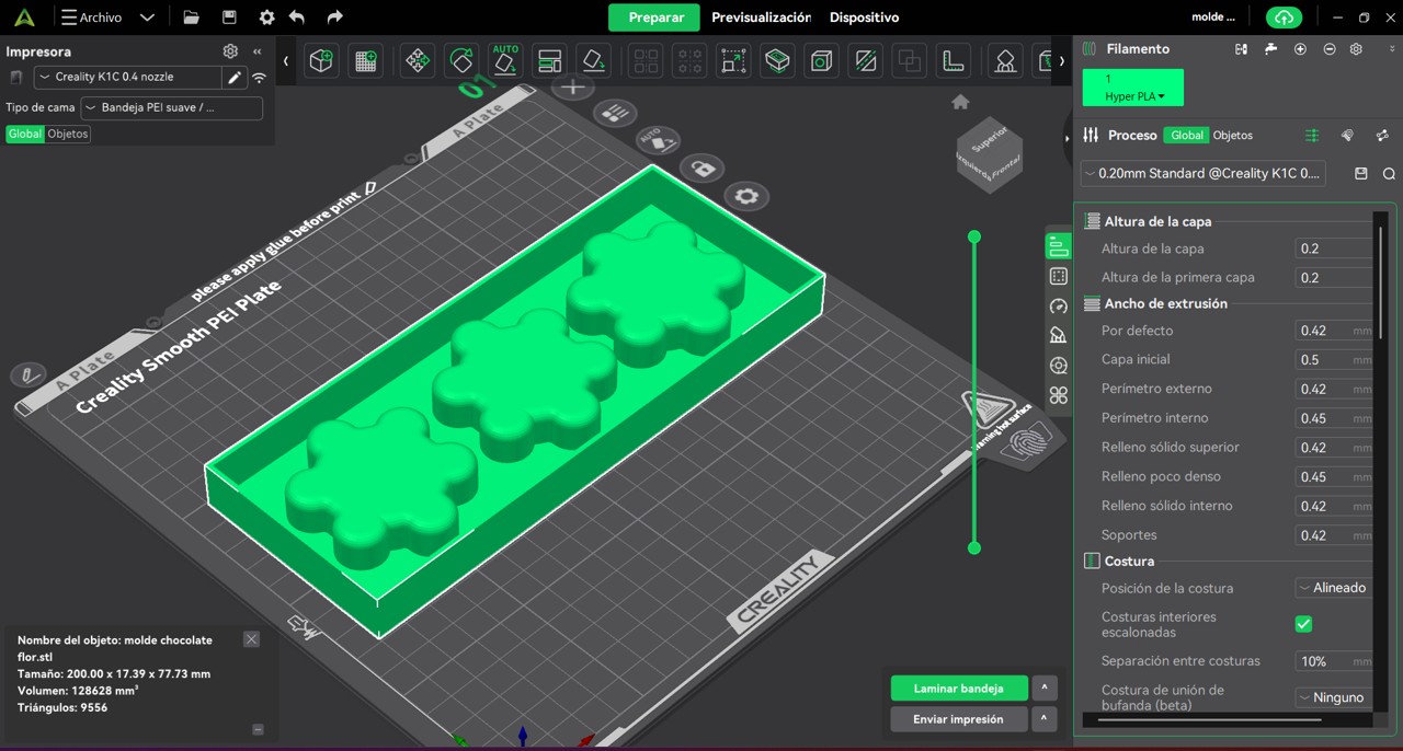
Img. 54: I used 20% infill, with a grid pattern, and enabled smoothing of the top layer.
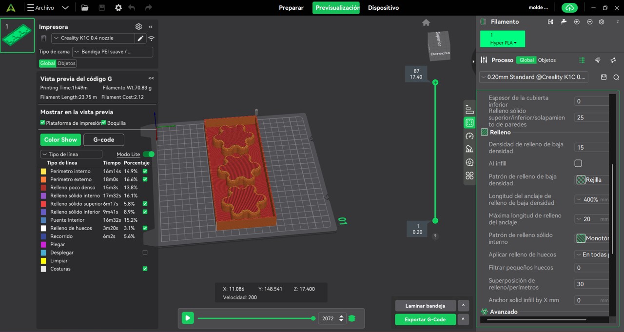
Img. 55: After slicing, the printing time was 1:49 h and the filament amount was 70.83 g or 23.75 m.
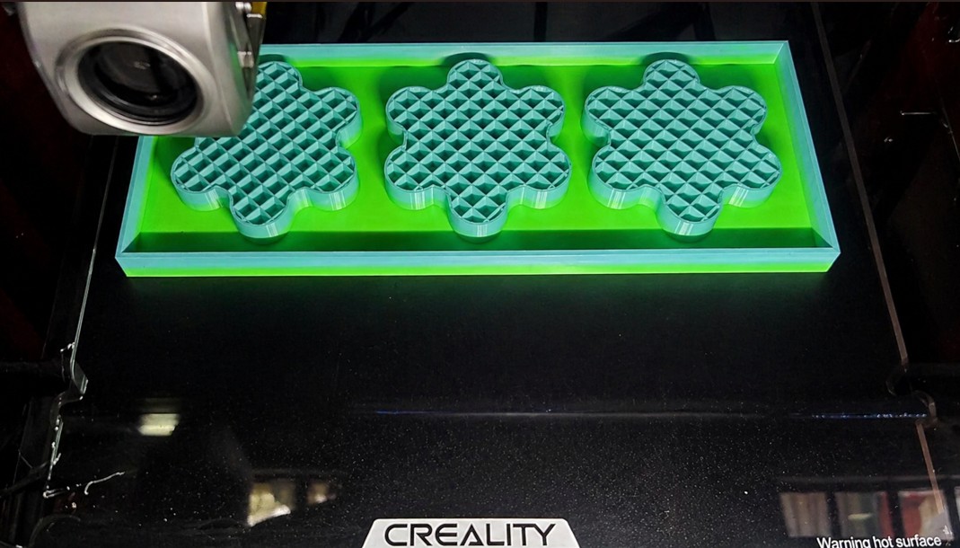
Img. 56: Mold printing process.
Img. 57: After sanding with wet sandpaper and cleaning, it was smooth, although some lines were still visible.
3. Preparation and Pouring of Food-grade Silicone
The silicone I used was purchased from SILICON PERÚ. You can review their website here: https://siliconperu.pe/.
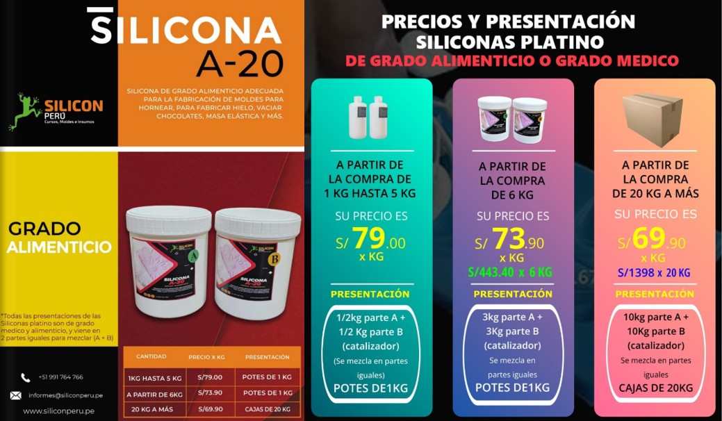
Img. 58: According to the supplier’s specifications, two equal parts of solution A and B are mixed. For this, I used an apron, gloves, hair cover, and mask.

Img. 59: To know the amount of silicone I needed, I filled my mold with rice, then poured the rice into a container and weighed it, obtaining 0.136 kg.
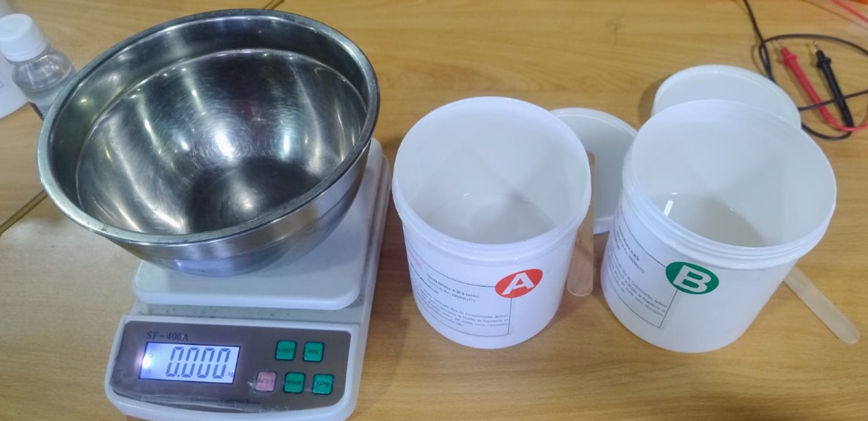
Img. 60: I rounded the obtained weight to 160 g to avoid running short, so I weighed 80 g of solution A and 80 g of solution B.
4. Mold Curing
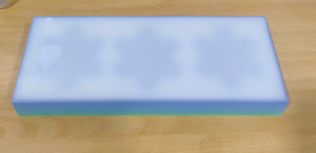
Img. 61: Curing was carried out inside a container to avoid contamination and was left overnight until total solidification.
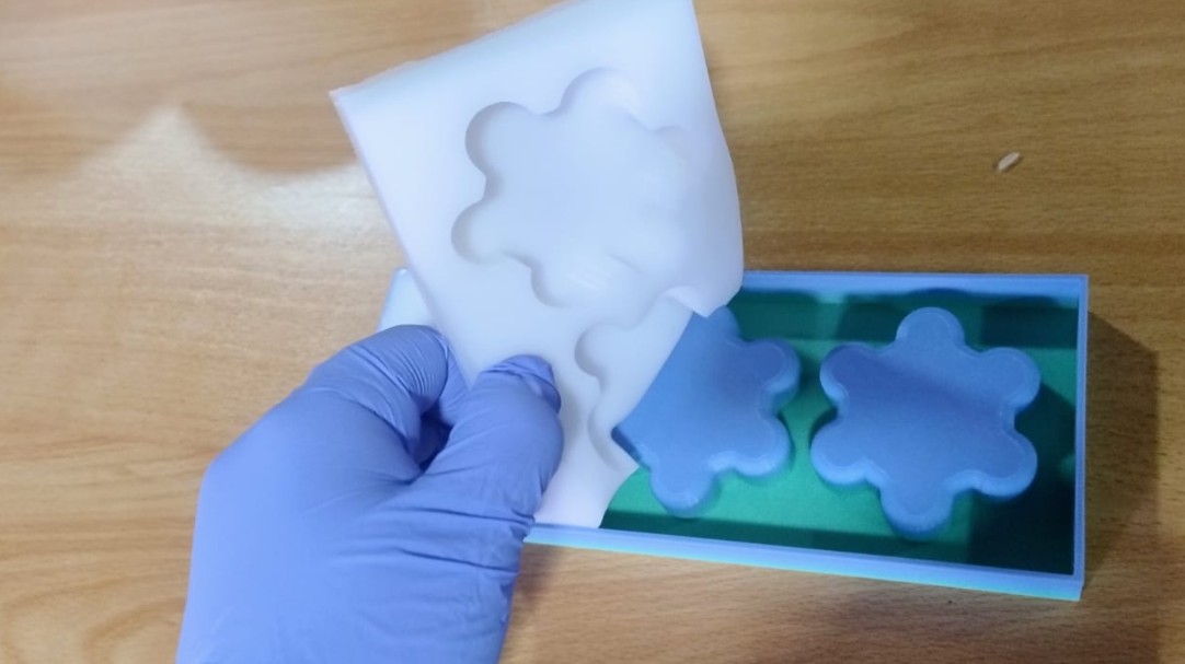
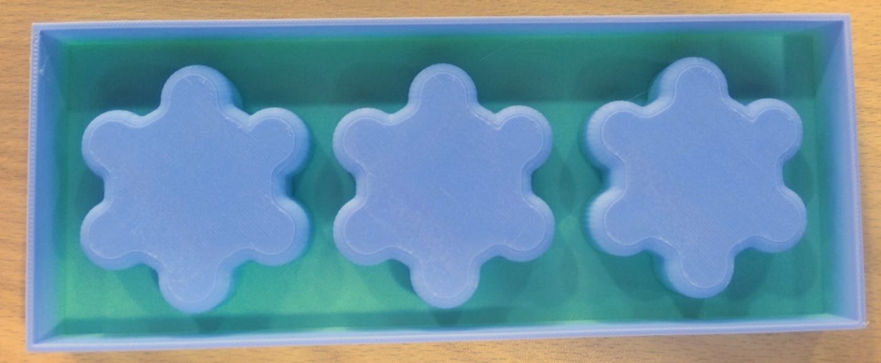
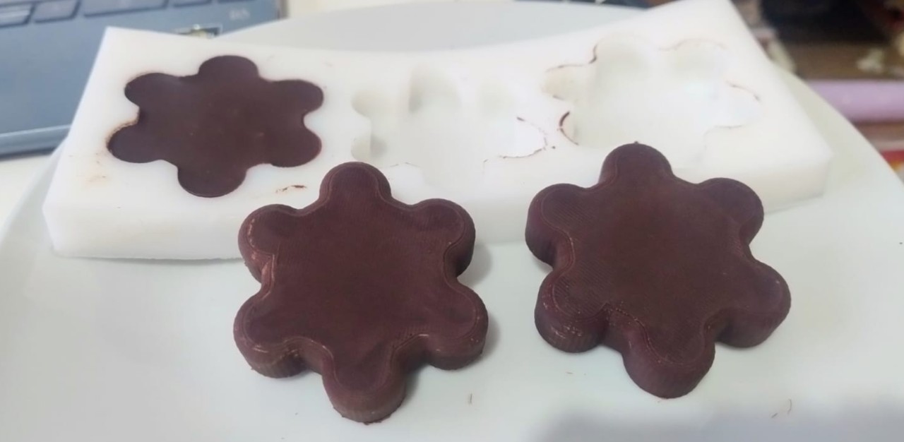
Img. 62: Demolding was done carefully to avoid breaks.
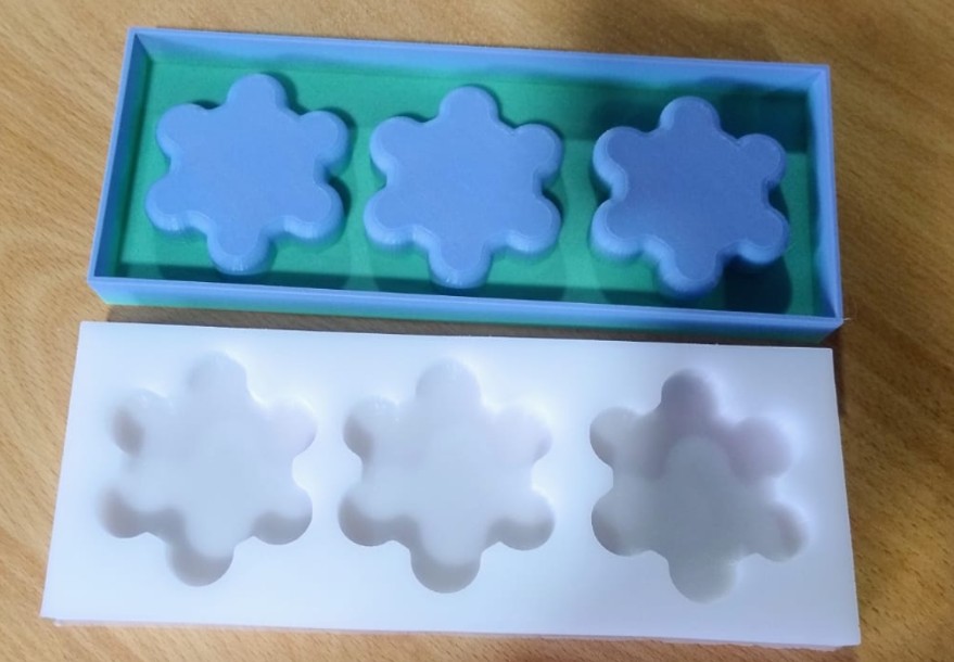
Img. 63: Final result of the silicone mold.
5. Casting with Melted Chocolate
Now, having the mold ready, I cast the chocolate. For this, I used chocolate produced by the Native Community of Boca Pariamanu. I worked with stainless steel containers to avoid contamination and used a double boiler to melt the chocolate paste. I had the help of my 5-year-old little girl, who was the most excited to eat the chocolates.
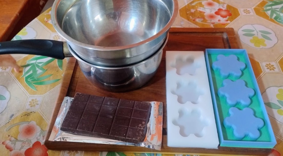
Img. 64: All materials ready to start working with the chocolate.
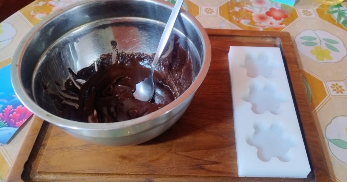
Img. 65: With the chocolate melted, it was poured into the mold.
Img. 66: It was left for about 4 hours in the refrigerator.
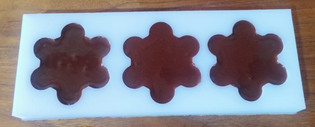
Img. 67: Final result of our flower-shaped chocolates.
6. Cooling and Demolding
The cooling and demolding process allowed the chocolates to maintain the flower shape created in the food-grade silicone mold.
2: Candle Mold
1. Model Design and 3D Printing of the Positive
For this part, since I got paraffin, I wanted to make a purple candle with bubbles, and although I did not have time to design it, I used a free STL file to test the finish directly in 3D printing. You can download the file here: Mold for stylish candle.
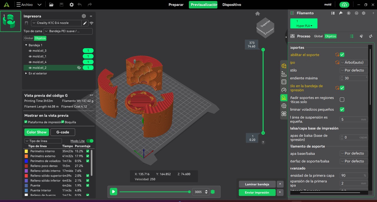
Img. 68: The print was configured similarly to the chocolate mold, but this time supports were required. The printing time was 3 h 53 m.
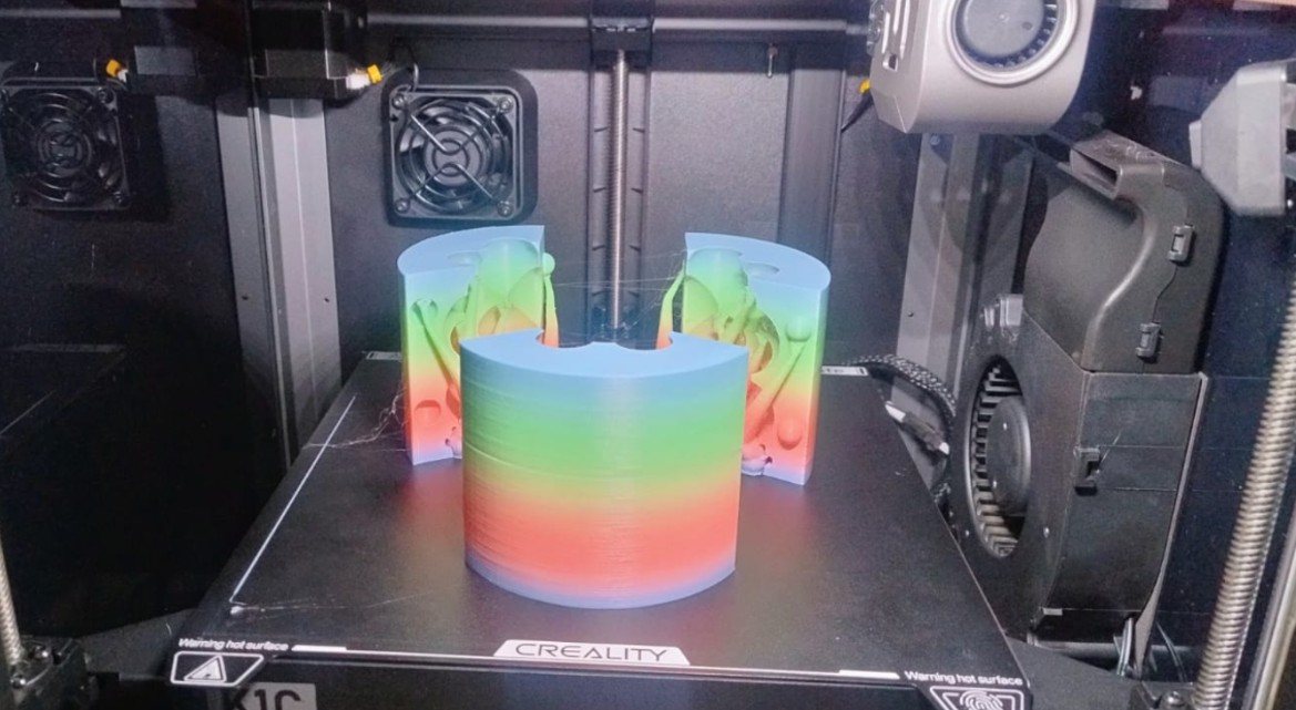
Img. 69: Although there was a power outage halfway through printing, when the print resumed, it was completed successfully.
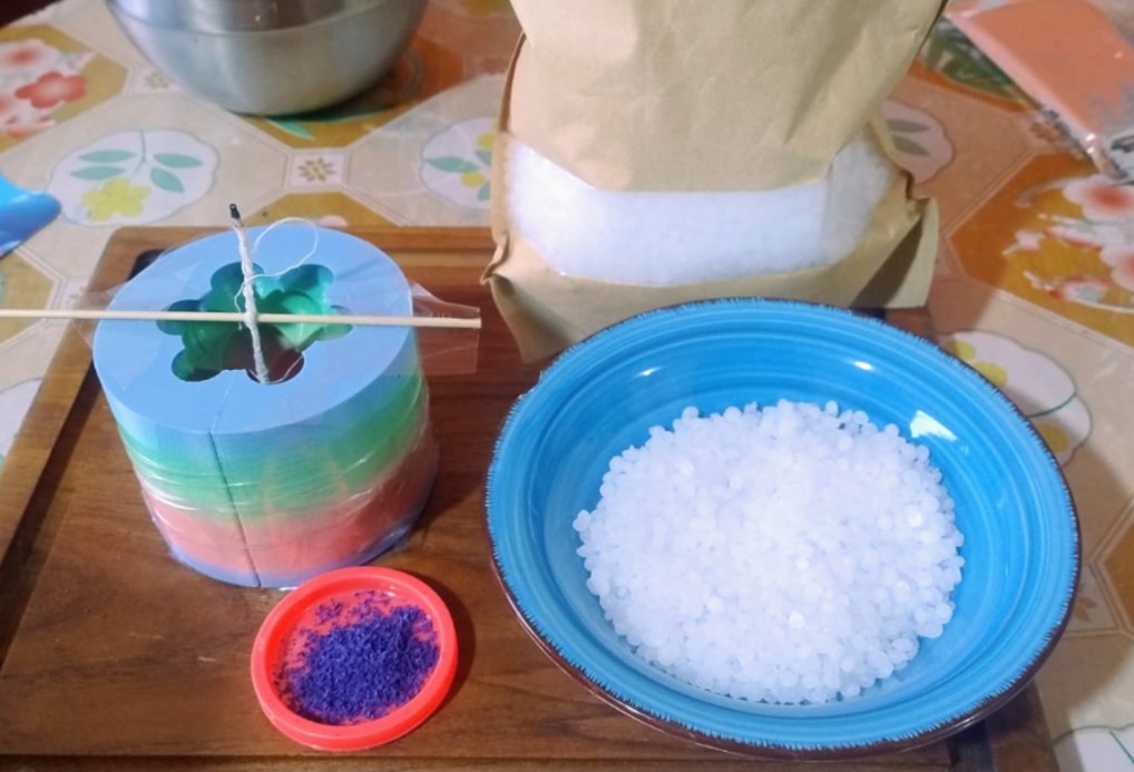
Img. 70: Materials ready to start making our purple bubble candle.
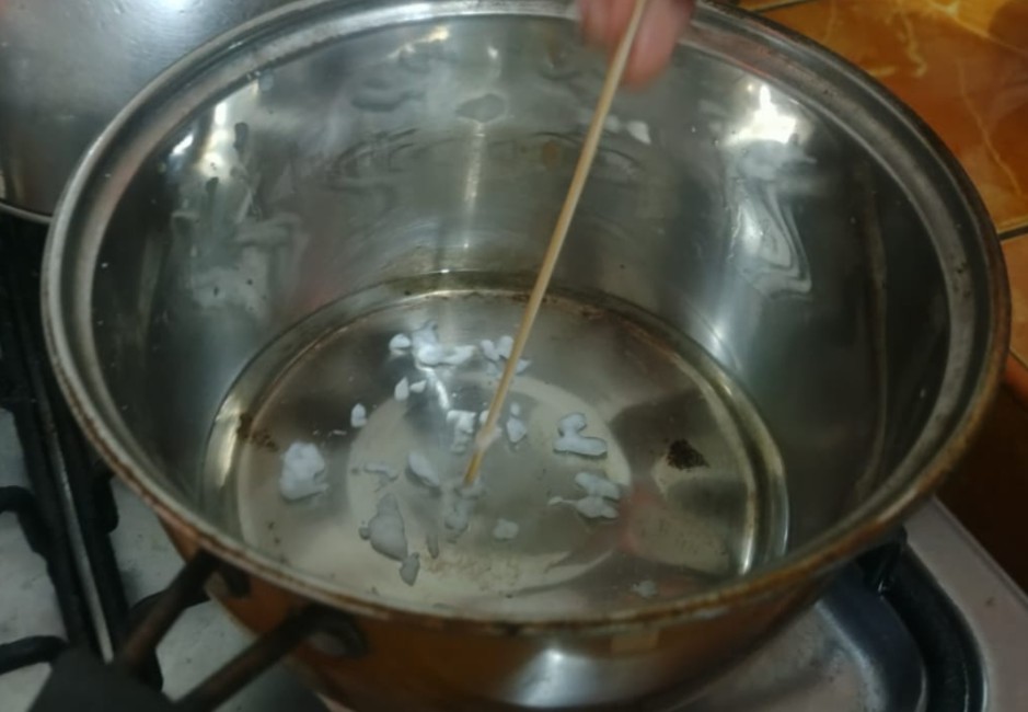
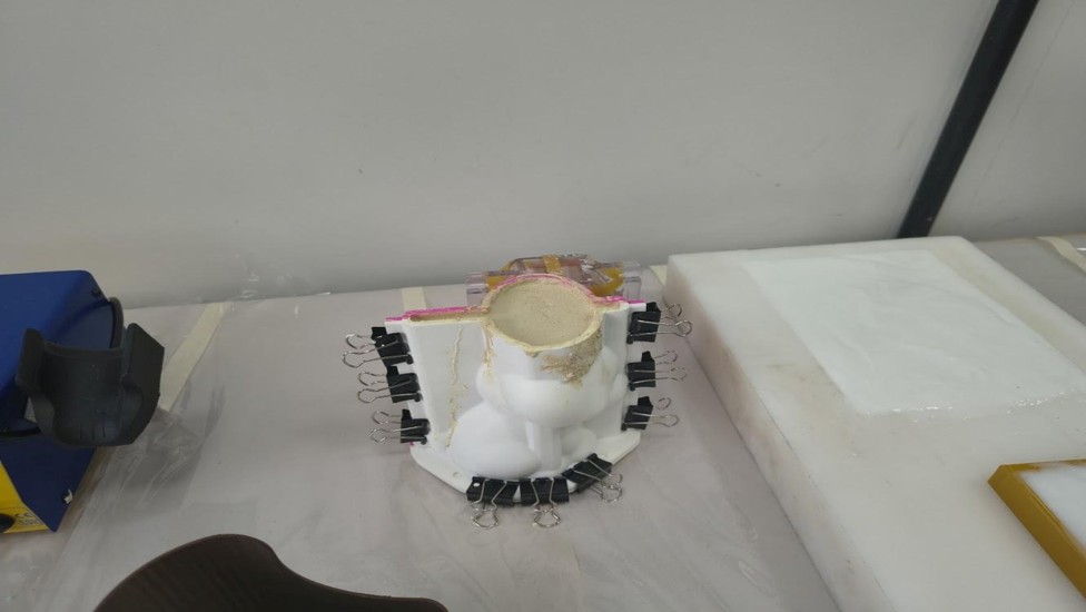
Img. 71: Melting the paraffin; to color it, we used a purple crayon from my little girl, who was excited and even helped me grate the crayon.
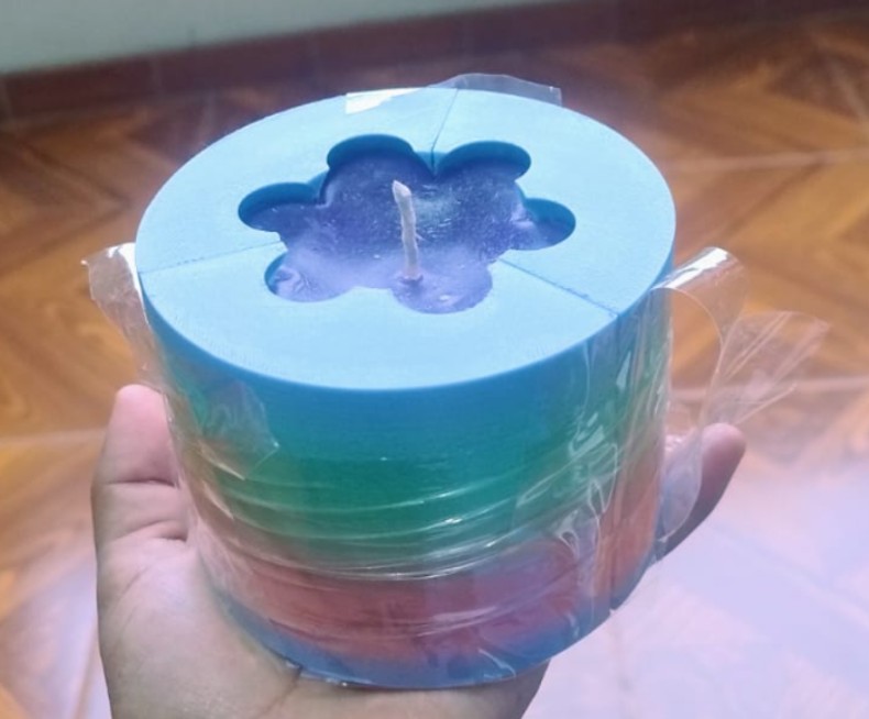
Img. 72: Since the design has three parts, to prevent the melted paraffin from leaking, it was sealed with packing tape. The candle was left to cure overnight.
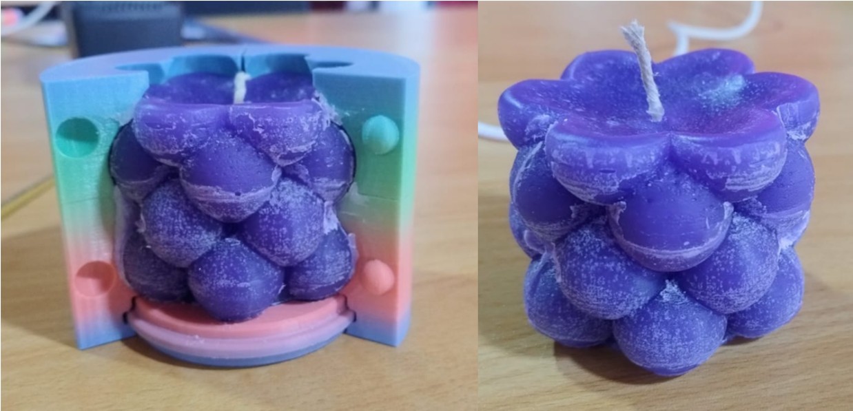
Img. 73: Final result of the candle.
III) Conclusions and Reflections
Conclusion of the Individual Project
The individual project allowed me to adapt the molding and casting process to the real conditions of the laboratory. Although the CNC machine could not be used due to a failure in the voltage stabilizer, 3D printing made it possible to continue the assignment and create functional master molds for chocolates and candles.
The use of food-grade platinum silicone made it possible to obtain a flexible and safe mold for casting chocolate. This process was especially meaningful because it responds to a real need in my region, where cacao production is important and customized chocolate molds are difficult to obtain due to distance and transportation costs.
The candle mold process also allowed me to test another casting material, paraffin, and to understand the importance of sealing, temperature control, and curing time. Although the candle mold came from a free STL file, it helped me explore another application of molding and casting using 3D printing as the fabrication method.
General Reflections of the Week
This week helped me understand that molding and casting is not only about pouring a material into a mold, but about carefully planning the complete process: design, material selection, surface finish, safety, preparation, pouring, curing, and demolding.
One of the most important lessons was the need to adapt to technical problems. The failure of the laboratory voltage stabilizer prevented the use of the CNC machine, but it also pushed me to look for an alternative process using the tools that were available, especially 3D printing.
I also learned that surface finish is very important when producing master molds. Even when the printed mold was sanded and cleaned, some layer lines were still visible, which showed me that future iterations should include more post-processing to improve the final mold quality.
Finally, this week connected digital fabrication with local productive opportunities. Making chocolate molds can be useful for cacao producers in Madre de Dios, while candle molds can be explored as a small creative and commercial product. This made the assignment feel more connected to my context and future projects.
IV) Final Reflections and Conclusions
Personal Reflections
This week was one of the most interesting experiences of Fab Academy because it combined design, materials science, fabrication processes, and creativity in a single assignment. I learned that molding and casting requires much more planning than it seems, since every detail influences the final result: the geometry of the mold, the surface finish, the release strategy, the type of material, the curing time, and the demolding process.
I also understood the importance of testing different materials. Working with silicone, wax, soap, plaster, chocolate, and paraffin allowed me to compare textures, flexibility, hardness, curing behavior, and surface quality. Each material has advantages and limitations, so selecting the correct one depends completely on the final application.
Another important lesson was adaptability. Due to the failure of the voltage stabilizer, I could not use the CNC machine in my laboratory. Instead of stopping the assignment, I used 3D printing as an alternative manufacturing method. This reminded me that digital fabrication is not only about machines, but also about problem solving and finding practical solutions with the available resources.
I especially enjoyed developing molds for chocolates because it connects directly with the productive reality of Madre de Dios, where cacao is an important local resource. It made me realize that Fab Academy projects can become real opportunities for entrepreneurship and innovation in my region.
Technical Conclusions
- Surface finish of the master mold directly affects the quality of the final casted part.
- CNC machining generally provides smoother and more precise molds than FDM printing, although printing is faster and more accessible.
- Controlled mixing and slow pouring reduce bubbles and defects.
- Correct curing time is essential to preserve geometry and avoid deformation.
- Food-grade silicone is an excellent option for chocolate molds due to its flexibility and safety.
- Biomaterials such as bio-silicone show strong potential for sustainable fabrication applications.
Final Conclusion of the Week
Molding and casting opened a new perspective for me inside digital fabrication. I discovered that it is possible to replicate objects efficiently, create customized products, and transform ideas into functional pieces using many different materials. This week strengthened both my technical skills and my confidence to continue developing useful products for education, entrepreneurship, and regional innovation.
Files & Downloads
This section includes the files used during the molding and casting process, including 3D models, STL files, and supporting fabrication files for chocolate and candle molds.