I) Group Project
For the machine development week, I had to travel to the city of Lima to meet with my classmates and work with them on this adventure of designing and building a machine for the first time. For this, I requested permission from work and started this journey.

Img. 1: Heading toward the construction of my first machine.

Img. 2: Traveling to Lima with the best company in the world, my little girl.
Machine Description: BIOCRUSHER
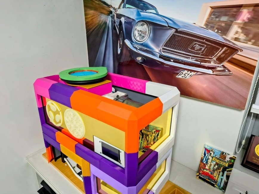
Img. 3: BIOCRUSHER machine concept.
Idea
BIOCRUSHER is a semi-automated machine designed to shred and process natural fibers and biomaterials using digital fabrication technologies, automation, and mechanical design. The project seeks to integrate shredding systems, automated movement, sensors, and control interfaces to facilitate the processing of organic materials that can later be used in the production of biomaterials, handmade paper, and other sustainable products.
The machine combines mechanical mechanisms, motors, sensors, safety systems, and an HMI interface with a Nextion screen to create a functional system oriented toward working with natural fibers and experimenting with biomaterials.
Problem it solves
The processing of natural fibers and biomaterials is usually done manually or with inefficient tools, making it difficult to obtain homogeneous material sizes and increasing the working time. In addition, many industrial machines are expensive, difficult to adapt, and not very accessible for educational projects, digital fabrication laboratories, or small experimental processes.
BIOCRUSHER seeks to solve this problem through a modular and accessible solution that allows fibrous materials to be shredded in a controlled and safe way. The machine facilitates the size reduction of natural fibers, optimizes the workflow, and allows part of the material handling process to be automated, while also integrating safety and monitoring systems.
The project also responds to the need to develop sustainable and experimental tools related to biomaterials and the use of local organic resources.
Prototype description
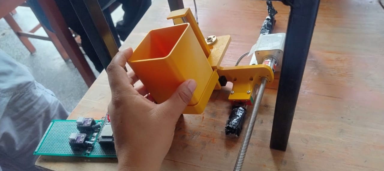
BIOCRUSHER is a dual-axis shredder prototype designed to cut and reduce the size of natural fibers using a mechanical system of interleaved blades. The system incorporates an iris-type feeding mechanism, a safety door with sensors, and an automated movement system for the collection container.
The machine uses a DC motor to drive the shredding system and NEMA motors to control the linear movement of the collection container in two axes. One motor controls the vertical movement on the Z axis, while another controls the horizontal movement on the X axis, allowing the container to be positioned to receive and move the processed material.
The prototype integrates an ESP32 microcontroller connected to a Nextion HMI touchscreen interface, which allows system states to be visualized, motors to be activated, sensors to be monitored, and basic operating parameters to be controlled.
The structure of the machine combines 3D printed parts, mechanical components, and laser-cut panels, allowing a modular, adaptable design that can be fabricated using digital fabrication tools.
II) Mechanical Design (Part 1 of 2) – Individual Contribution
During the ideation stage, I participated virtually. In this first part of the project, I contributed machine ideas that we could develop. It was an endless list of possibilities, for example: an automatic planter, fish feeder, shot dispenser, solar panel cleaner, and many more. Each group member contributed ideas and suggestions. In the end, we decided to work on the idea of developing a shredder for biomaterials, because it addressed a social solution and contributed to the bioeconomy. This is what attracted me to this idea. We then began with prototyping; to do this, we described the biomaterial production process and decided to work on the shredding stage.
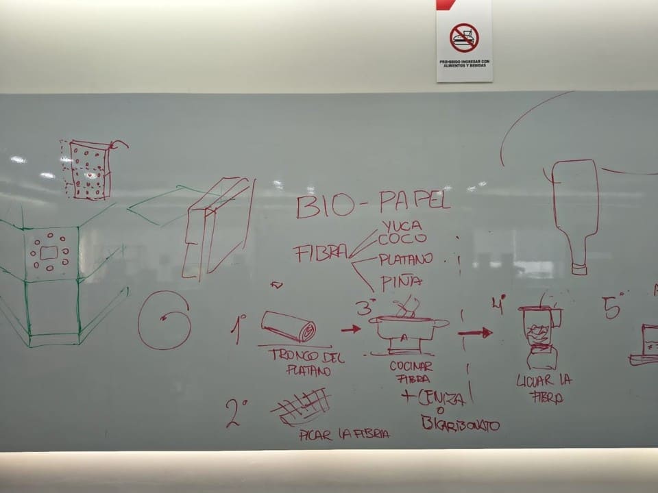
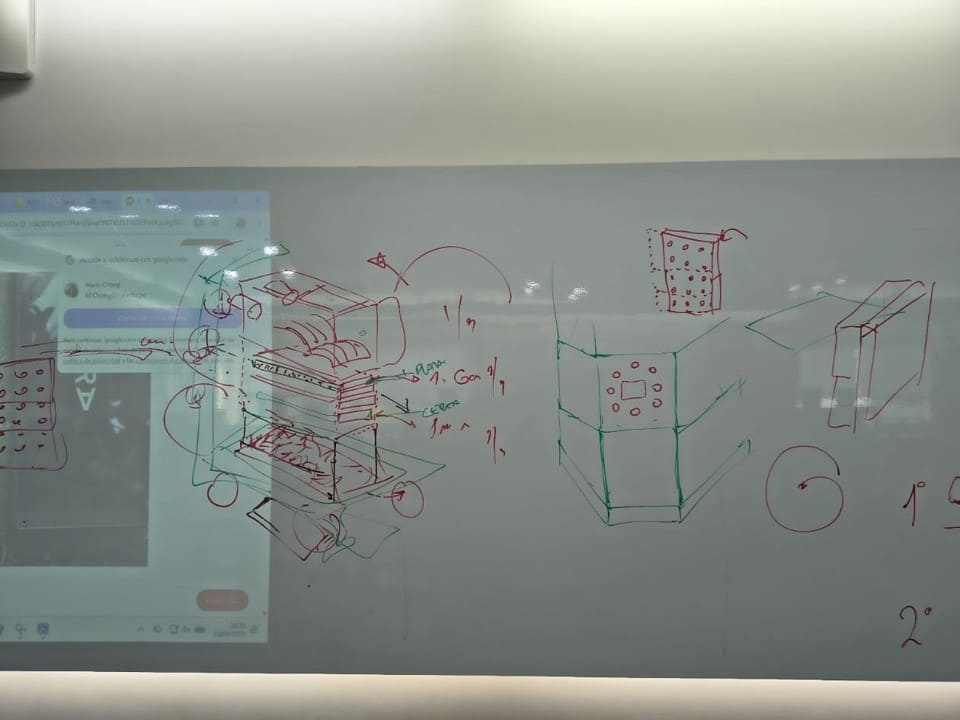
Img. 4: Understanding the biomaterial process flow.
Img. 5: Initial modular prototype.
Once we decided on the machine, we worked on making it tangible. There were hours and hours of thinking about the system and the sensors it should have. At this point, it helped us a lot to take inspiration from paper shredders and other shredders that already existed, and then to design the mechanical and electronic parts of the machine.
In this part, my contribution was mainly in the planning of the electronic and automated system of the BIOCRUSHER machine. I participated in defining the general operation of the system, especially the safety logic, user interface, and automated movement of the collection container.

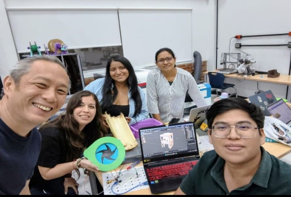
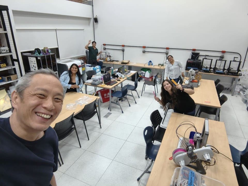
Img. 6: First meeting with the team at FAB LAB UNI.
Later, we realized that the machine should have some kind of numerical control, and that it would be even better if it had movement along the X, Y, and Z axes. We thought a lot about how to include this. Initially, we thought about adding a conveyor belt, but it did not add much value. Then I came up with the idea that, to make the machine more dynamic, we could add a system to deliver the finished product.
I supported the proposal of the displacement system using NEMA motors, where one motor controls the vertical movement on the Z axis and another controls the horizontal movement on the X axis for the delivery of the shredded material. In operation, the system receives the shredded material at the hopper outlet, then lowers along the Z axis and moves forward along the X axis to deliver the product.
Components investigated for the displacement system
| Component |
Quantity |
Use within the system |
| NEMA 17 / NEMA 23 motor | 2 | Used to generate automated movement of the collection system. One motor controls vertical movement on the Z axis and the other controls horizontal movement on the X axis. |
| TB6600 / A4988 driver | 2 | Stepper motor controllers. They regulate direction, speed, and step commands sent from the ESP32. |
| Lead screw | 2 | Converts the rotational motion of the NEMA motors into precise linear movement to move the collection container. |
| Flexible coupling | 2 | Connects the motor shaft to the lead screw, helping reduce vibration and mechanical misalignment. |
| Linear guides | 2 | Allow stable and aligned movement of the mobile system along the X and Z axes. |
| Linear bearings | 4 | Reduce friction and allow smooth movement of moving parts along the linear guides. |
| 3D printed supports | Several | Used to hold motors, guides, sensors, and structures of the displacement system. |
| Limit switches | 2 | Sensors used to detect movement limits and prevent overtravel of the linear system. |
| ESP32 | 1 | Main microcontroller responsible for controlling motors, sensors, and communication with the Nextion screen. |
| 24V power supply | 1 | Powers the NEMA motors, drivers, and part of the machine's electronic system. |
| Screws and nuts | Variable | Fastening elements used to assemble the structures and moving mechanisms. |
After understanding how this worked, the assembly and programming were carried out with the help of my classmates.
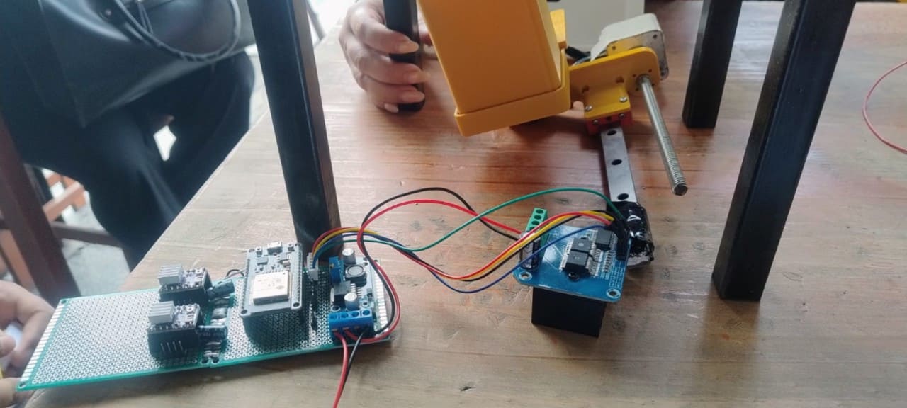
Img. 7: Rail assembly.
Img. 8: NEMA motor operating tests.
I also participated in defining the safety system to ensure that the machine only works when the door remains closed.
In addition, I collaborated in the initial organization of the group documentation by collecting photographs, videos, and evidence of the assembly and mechanical design process. I participated in the visual planning of the group webpage and in the structuring of galleries and sections for the Fab Academy documentation.
III) Machine Design (Part 2 of 2) – Individual Contribution
During the second part of the project, my contribution was mainly focused on automation, electronic integration, and technical documentation of the system.
We wanted to work with an OLED screen, but a friend told us about the Nextion screen and we were amazed by the idea. I was assigned to develop this part. At first it was difficult because I wanted to configure a very professional interface, but considering the time available, I had to make a basic configuration. Here I describe the step-by-step process I followed, as well as more information about Nextion screens.
Nextion HMI Screen
The Nextion HMI (Human Machine Interface) screen is an intelligent touchscreen interface used to facilitate interaction between the user and electronic or automated systems. This screen allows real-time information to be displayed and different machine functions to be controlled through buttons, indicators, graphics, and interactive menus.
In the BIOCRUSHER project, the Nextion screen was used as the main control and monitoring interface of the machine. Through it, it is possible to visualize system states such as motor operation, safety door status, feeding iris activation, collection container position, and operation time.
The screen communicates directly with the ESP32 microcontroller through UART serial communication, allowing data to be sent and received between the graphical interface and the automated system. Thanks to this, the user can interact with the machine in a more intuitive and safe way without directly manipulating code or electronic circuits.
In addition, using an HMI interface improves the user experience, facilitates system testing, and allows visual elements to be integrated to help monitor and validate machine operation.
Components required for the Nextion HMI system
| Component |
Quantity |
Use within the system |
| Nextion 3.5" screen | 1 | Used as the main control and monitoring interface of the machine. It allows states to be visualized, functions to be activated, and system operation to be supervised. |
| ESP32 DevKit | 1 | Microcontroller responsible for communicating with the Nextion screen and processing the commands sent from the HMI interface. |
| FT232BL Mini USB Converter | 1 | Adapter used to upload and program the graphical interface developed for the Nextion screen. |
| TTL / I2C logic level converter | 2 | Adapts voltage levels between the Nextion screen and other electronic modules for stable and safe communication. |
| Dupont / 24AWG wiring | Several | Used for serial connections and power supply between the Nextion screen and the ESP32. |
I was pleasantly surprised that it was not cheap at all, but since the order had already been made, we continued. In the end, the price was worth the experience of learning to use this screen.
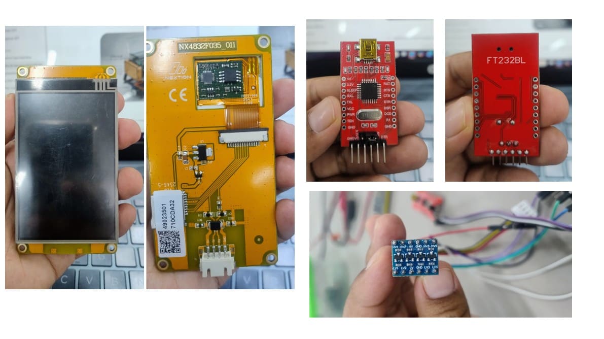
Img. 9: Components used for the Nextion HMI interface system.
The image shows the main electronic components used for the development and programming of the interface system of the BIOCRUSHER project. On the left side, the 3.5” Nextion HMI touchscreen is shown from the front and back. On the upper right side, the FT232BL USB-to-serial converter is shown, which was used to upload and configure the graphical interface on the screen. At the bottom, the bidirectional logic level converter module is shown, used to adapt voltage levels and ensure stable serial communication between the ESP32 and the Nextion screen.
I worked on communication tests between the Nextion screen and the ESP32 microcontroller, validating the HMI interface and the sending of information related to the machine status.
IV) Basic Step-by-Step Process to Program a Nextion HMI Screen
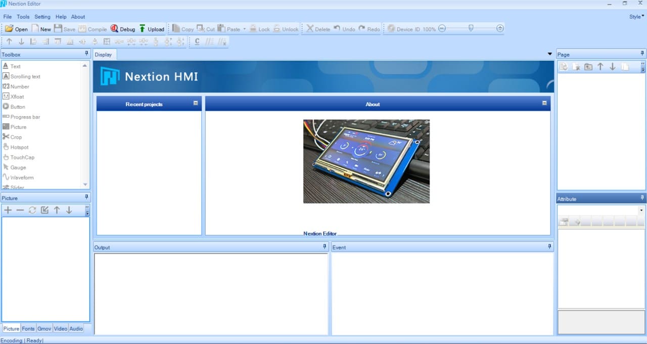
1. Download Nextion Editor
First, the official program called Nextion Editor must be downloaded. This software is used to design the graphical interface of the HMI screen.
Official download page: Nextion Editor Official Download
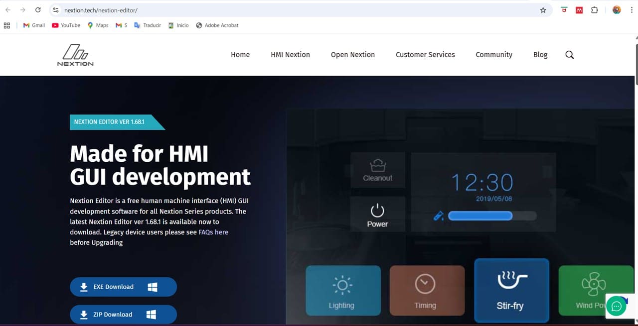
Img. 10: Official Nextion page.
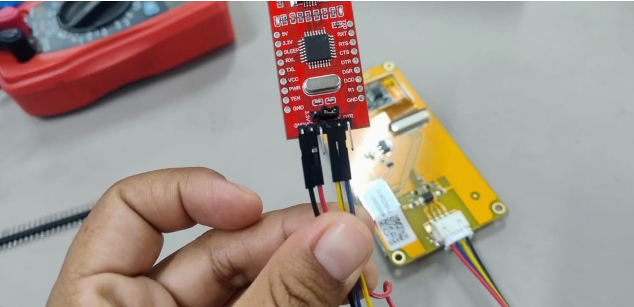
Img. 11: Connecting the Nextion screen with the FT232BL, used to upload and configure the graphical interface on the screen.
Official Nextion guide: Nextion Editor Guide
We downloaded the .EXE version for Windows and installed the program. During installation, Windows requested the installation of .NET Framework, which was accepted to allow the editor to function correctly.
2. Create a new project
We opened Nextion Editor and selected:
File → New
Then:
- We saved the .HMI file.
- We selected the screen model: Discovery → NX4832F035_011.
- We chose horizontal orientation: 90° Horizontal.
- Finally, we pressed OK.
Img. 12: Nextion screen connection.
Img. 13: Project creation.
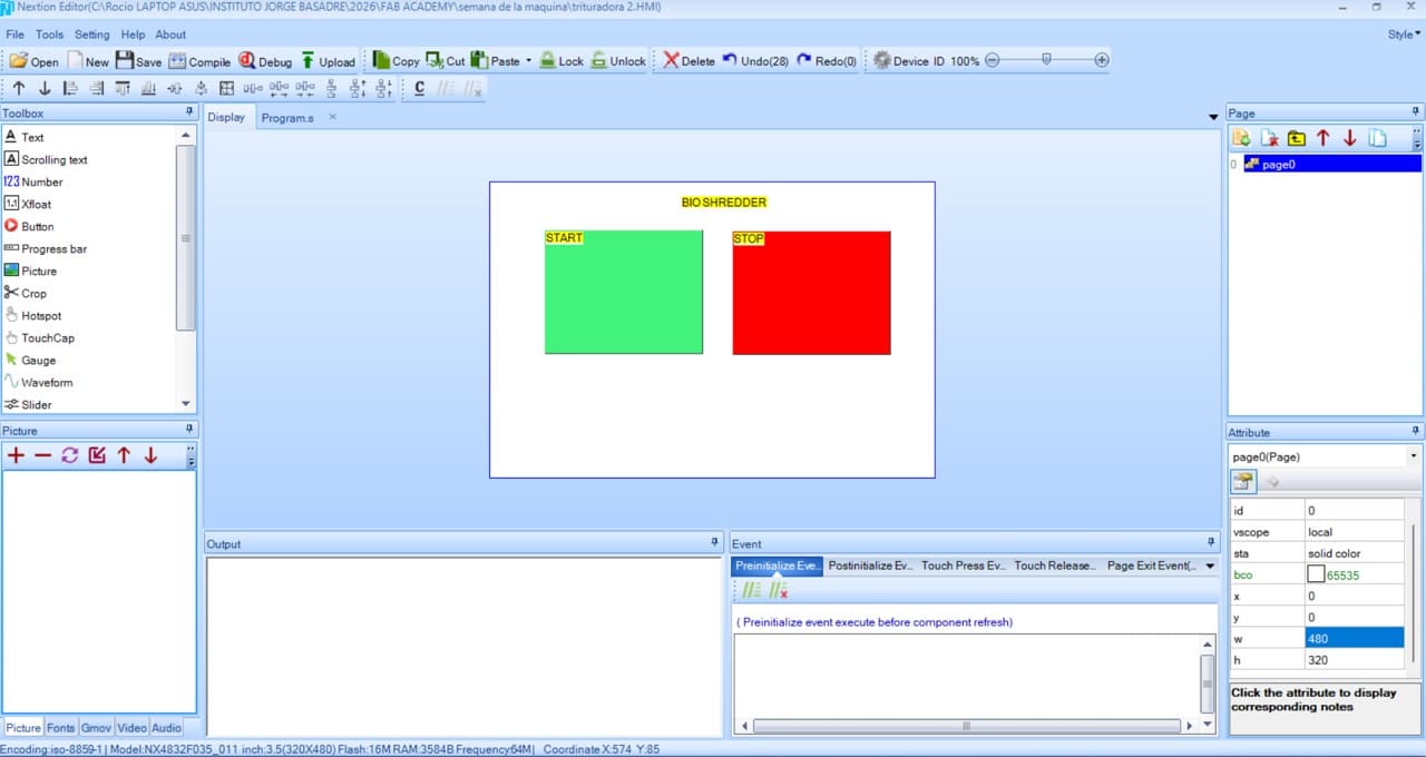
3. Initial screen configuration
Once the project was created, the editor automatically generated a page called page0. This page was used as the main control screen of the machine.
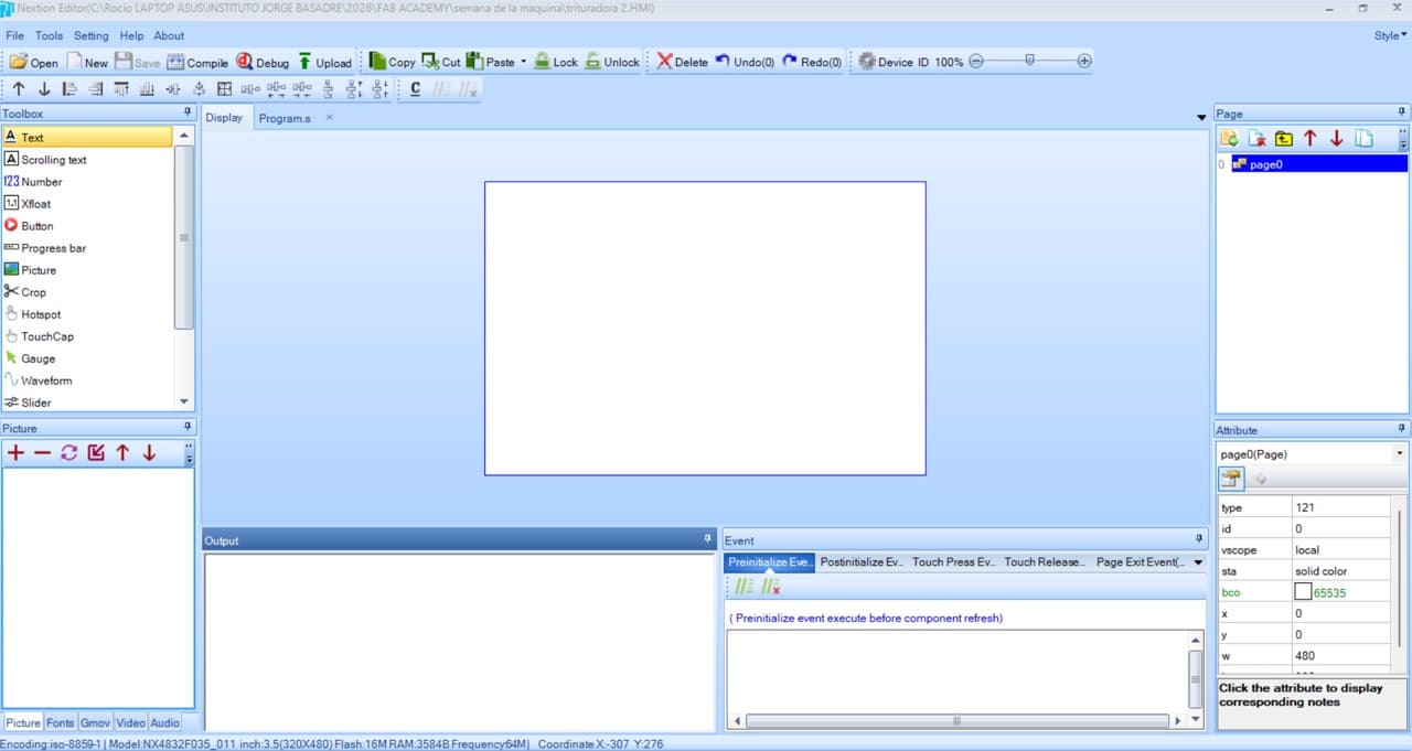
Img. 14: Screen interface configuration.
4. Background configuration
We selected the main page (page0) and modified the following parameters:
| Parameter | Value |
|---|
| Background color | Blue |
| Width | 480 |
| Height | 320 |
This allowed us to work with the real size of the Nextion 3.5” screen.
5. Add text elements
From the left panel (Toolbox), we dragged Text components. The added texts were:
- CRUSHER CONTROL
- MOTOR
- DOOR
- IRIS
- CLOSED
- REMOVE CUP
Each text was configured from the attributes panel:
| Property | Use |
|---|
| txt | Displayed text |
| font | Size and style |
| pco | Text color |
| bco | Background color |
6. Create visual status bars
To visually represent the motor and iris operation, Progress Bar objects were used. These bars were configured with colors such as red, green, and dark brown, simulating levels of operation and activation.
Img. 15: Interface design.
7. Create numeric indicators
Number objects were added to show motor percentage and iris percentage. These indicators allow values sent from the ESP32 through serial communication to be received.
8. Create safety states
Text boxes were added to show: DOOR → CLOSED. This indicator was designed to show the safety status of the machine protection door. The future logic will allow:
- CLOSED → machine enabled
- OPEN → machine blocked
9. Create container alert
A warning box was added: REMOVE CUP. This element was designed to indicate when the collection container must be removed or emptied.
10. Visual organization of the interface
The interface was designed using:
- horizontal layout
- high-contrast colors
- large text
- simple indicators
This facilitates quick monitoring, intuitive control, and visual reading during machine operation.
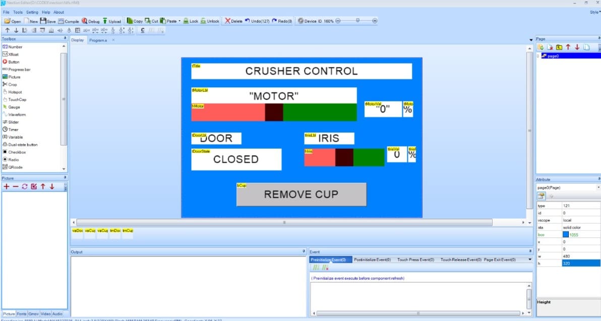
Img. 16: Final interface created.
11. Compile the project
After finishing the design, we selected Compile. This generated the .TFT file, which was later uploaded to the Nextion screen.
12. Next step
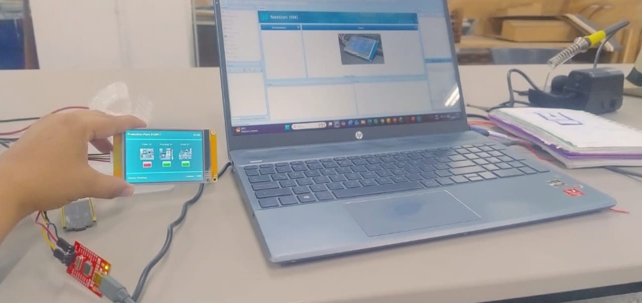
The next step was to connect the screen with the ESP32, send serial data, update states in real time, and control sensors and motors from the HMI interface.
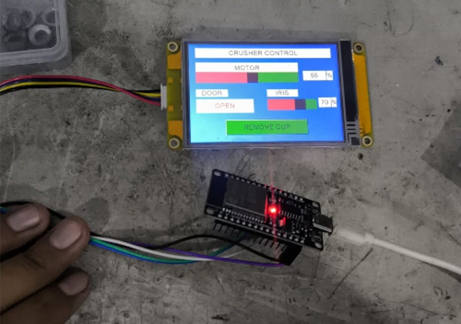
Img. 17: Functionality test with the ESP32.
V) 3D Printing Support and Group Documentation
I also contributed to the development of the machine structure by supporting 3D printing, which was carried out both at the FAB LAB of UNI and at the FAB LAB of UP.
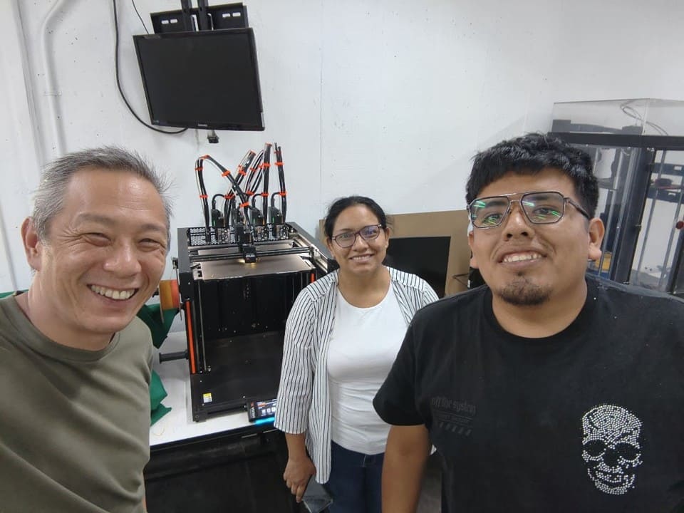
Img. 18: 3D prints at the UNI laboratory.
Img. 19: 3D prints at the UP laboratory.
Finally, I actively participated in the group documentation in HTML for Fab Academy, organizing technical content, images, GIFs, videos, and descriptions related to electronics, automation, and machine operation.
VI) Reflections
During the Mechanical Design and Machine Design week, I understood the importance of integrating different areas such as mechanical design, automation, programming, and user interfaces into a single functional project. One of the most enriching experiences was working on the development of the HMI interface using the Nextion screen, since it allowed me to understand how a machine can communicate visually with the user in an intuitive and safe way.
I was also able to strengthen my skills in technical documentation, information organization, and visual validation of the project, which are fundamental aspects within Fab Academy. The process of designing screens, organizing operating states, and thinking about the user experience helped me understand that a machine must not only work mechanically, but must also be understandable and easy to operate.
Another important reflection was the value of collaborative work. By working with classmates from different cities and specialties, we learned to distribute tasks, solve technical problems, and complement our skills to advance the project. Constant communication and the ability to adapt were key to integrating all parts of the machine.
In addition, this week allowed me to connect digital fabrication with real and sustainable problems, especially in the processing of biomaterials and natural fibers, which connects with my interest in technologies applied to the use of local resources and technological education.
VII) Conclusions
- A functional HMI interface was developed using a 3.5” Nextion screen, allowing the operating states and control of the BIOCRUSHER machine to be visualized.
- My main contribution was focused on the design, configuration, and validation of the graphical interface of the system, as well as the supervision of the integration between the Nextion screen, the ESP32, and the automated systems of the machine.
- A visual interface was designed capable of showing motor indicators, safety door states, iris activation, and alerts related to the collection container.
- The development of this week allowed me to understand the importance of integrating mechanics, electronics, programming, and visual interaction within an automated system.
- The experience strengthened skills related to interface design, technical documentation, system organization, and multidisciplinary collaborative work.
- The project demonstrated that digital fabrication and automation can be applied to sustainable solutions oriented toward the processing of biomaterials and local natural resources.
- Future improvement opportunities were identified, such as incorporating more sensors, real-time monitoring, advanced automation, and dynamic data visualization within the HMI interface.