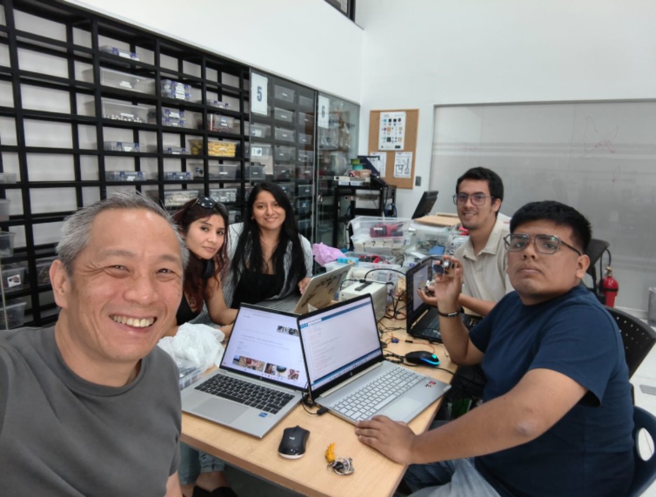
This group work was developed at Universidad del Pacifico. I worked remotely with my group, since I could not travel to Lima. The objective was to implement a communication system between devices using the MQTT protocol, allowing the sending and receiving of messages through a broker using the publish/subscribe model. During the development, joint tests were carried out to validate the communication flow, verify the correct transmission of messages, and ensure the operation of the nodes involved.
Objective
Send messages between two projects
Implement a communication protocol (MQTT)
Understand the publish/subscribe model
Validate real-time data transmission
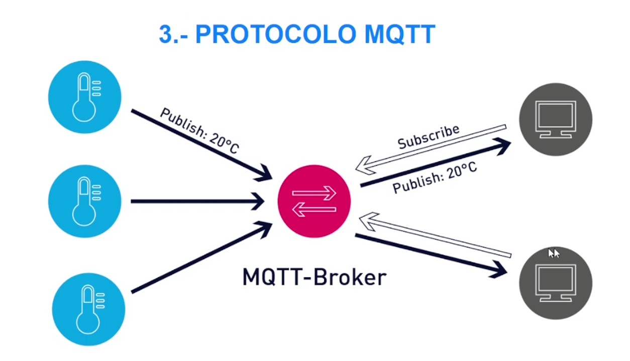
System architecture
The implemented system is composed of three main elements: 1) Broker, broker used: broker.emqx.io, port: 1883. The broker acts as an intermediary, in charge of receiving and distributing messages between devices. 2) Publisher (sending node), tool used: MQTTX, function: send messages to a topic. 3) Subscriber (receiving node), device: ESP32, function: receive messages and process them.
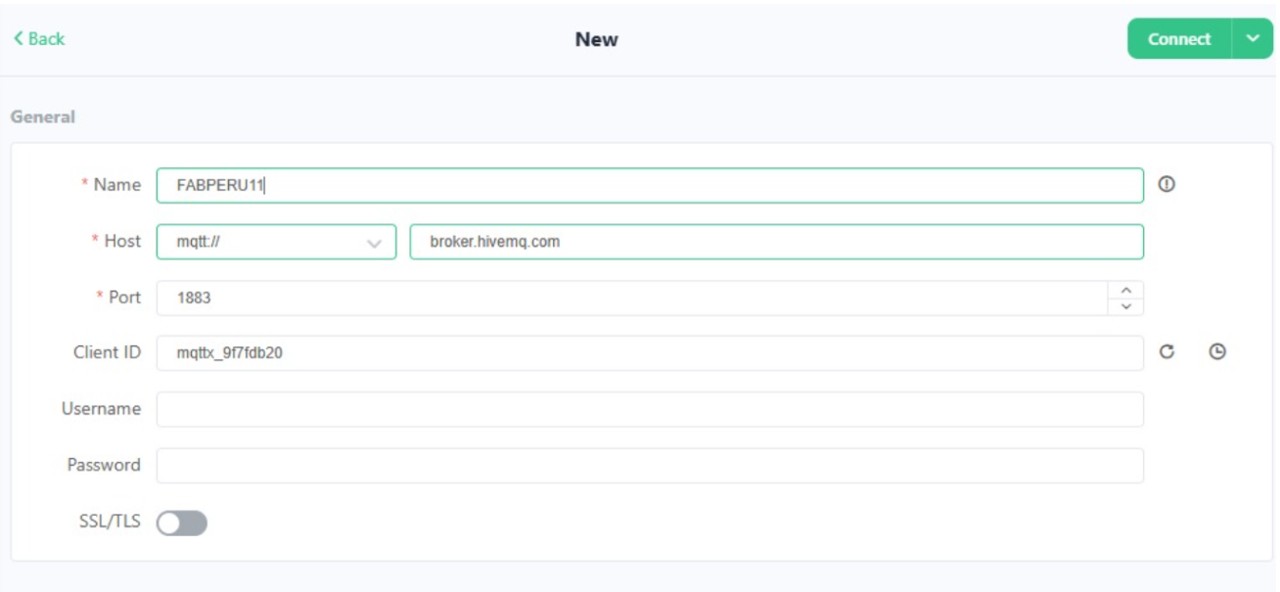
Img 1: A new connection was created with the topic: FABPERU11
The code that was used:
// Programming Project 1 - Counter with OLED display - Client
                      // TU_WIFI

                  #include                //Library for WiFi connection
                  #include        //Library for MQTT client communication
                  #include                //Library for I2C communication
                  #include        //Library for graphics on OLED
                  #include    //Library for OLED display

                  #define SCREEN_WIDTH 128        // OLED display width, in pixels
                  #define SCREEN_HEIGHT 64        // OLED display height, in pixels

                  Adafruit_SSD1306 display(SCREEN_WIDTH, SCREEN_HEIGHT, &Wire, -1);   // Create an instance of the OLED display

                  // WiFi
                  const char* ssid = "IoT_UP";                  //WiFi network name
                  const char* password = "ti6WzfPsk3WnqZpt8d";  //WiFi network password

                  // MQTT
                  const char* mqtt_server = "broker.emqx.io";   //MQTT broker address

                  WiFiClient espClient;                         // Create a WiFi client object
                  PubSubClient client(espClient);               // Create an MQTT client object using the WiFi client

                  String mensaje = "";             // Variable to store the received message
                  bool nuevoMensaje = false;       // Flag to indicate if a new message has been received

                  void setup() {
                    Serial.begin(115200);         // Start serial communication for debugging

                    // OLED
                    Wire.begin(D4, D5);                         // Initialize I2C communication with specified SDA and SCL pins
                    display.begin(SSD1306_SWITCHCAPVCC, 0x3C);  // Initialize the OLED display with the I2C address 0x3C

                    display.clearDisplay();                    // Clear the display buffer
                    display.setTextSize(2);                    // Set text size to 2 (double the normal size)
                    display.setTextColor(SSD1306_WHITE);       // Set text color to white
                    display.setCursor(0, 20);                  // Set the cursor position to (0, 20) for text display
                    display.println("Contador");               // Print "Contador" on the OLED display
                    display.display();                         // Update the OLED display with the contents of the display buffer

                    // WiFi
                    WiFi.begin(ssid, password);               // Connect to the WiFi network using the specified SSID and password
                    while (WiFi.status() != WL_CONNECTED) {
                      delay(500);                             // Wait until the WiFi connection is established
                    }

                    // MQTT
                    client.setServer(mqtt_server, 1883);      // Set the MQTT broker address and port for the client
                    client.setCallback(callback);            // Set the callback function to handle incoming MQTT messages
                  }

                  void reconnect() {
                    while (!client.connected()) {           //  Keep trying to connect until the MQTT client is connected
                      if (client.connect("XIAO_OLED")) {    // Attempt to connect to the MQTT broker with the client ID "XIAO_OLED"
                        client.subscribe("fabacademy/contador");// Subscribe to the MQTT topic "fabacademy/contador" to receive messages published to that topic
                      } else {
                        delay(2000);                        // Wait before retrying to connect if the connection attempt fails
                      }
                    }
                  }

                  void callback(char* topic, byte* payload, unsigned int length) {
                    mensaje = "";                           // Clear the message variable before processing the new message

                    for (int i = 0; i < length; i++) {      // Iterate through the payload bytes and append them to the message string
                      mensaje += (char)payload[i];         // Convert each byte in the payload to a character and append it to the message string
                    }

                    Serial.println(mensaje);              // Print the received message to the serial monitor for debugging
                    nuevoMensaje = true;                  // Set the flag to indicate that a new message has been received and is ready to be displayed on the OLED
                  }

                  void loop() {
                    if (!client.connected()) {
                      reconnect();                        //  If the MQTT client is not connected, call the reconnect function to establish a connection to the MQTT broker
                    }
                    client.loop();

                    if (nuevoMensaje) {                   // If a new message has been received, update the OLED display with the new message
                      display.clearDisplay();
                      display.setTextSize(3);
                      display.setTextColor(SSD1306_WHITE);
                      display.setCursor(20, 20);
                      display.println(mensaje);           // Print the received message on the OLED display
                      display.display();

                      nuevoMensaje = false;
                    }
                  }
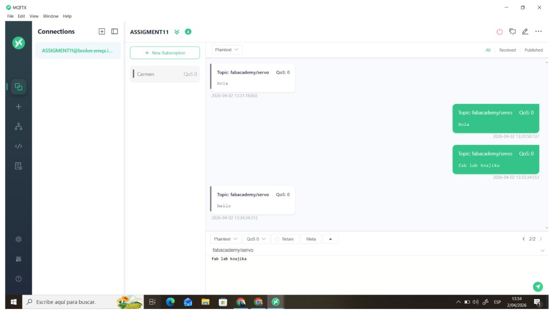
Img 2: A publication was sent to check the connection
And the following code was used:
// Programming Project 2 - Button counter with MQTT - Server
                       // TU_WIFI

                #include                              //Library for WiFi connection
                #include                      //Library for MQTT client communication

                // WiFi
                const char* ssid = "IoT_UP";                  //WiFi network name
                const char* password = "ti6WzfPsk3WnqZpt8d";  //WiFi network password

                // MQTT
                const char* mqtt_server = "broker.emqx.io";   //MQTT broker address

                WiFiClient espClient;                         // Create a WiFi client object
                PubSubClient client(espClient);               //  Create an MQTT client object using the WiFi client

                int boton = D7;                               // Define the pin for the button (change to the GPIO/pin you are using)
                int contador = 0;                             // Variable to store the count of button presses
                bool estadoAnterior = HIGH;                   // Variable to store the previous state of the button (initialized to HIGH assuming the button is not pressed)

                void setup() {
                  Serial.begin(115200);                       // Start serial communication for debugging
                  pinMode(boton, INPUT_PULLUP);              // Set the button pin as an input with an internal pull-up resistor (assuming the button is active LOW)

                  WiFi.begin(ssid, password);               // Connect to the WiFi network using the specified SSID and password
                  while (WiFi.status() != WL_CONNECTED) {   //  Wait until the WiFi connection is established
                    delay(500);
                  }

                  client.setServer(mqtt_server, 1883);      // Set the MQTT broker address and port for the client
                }

                void reconnect() {
                  while (!client.connected()) {           // Keep trying to connect until the MQTT client is connected
                    client.connect("XIAO_BOTON");         // Attempt to connect to the MQTT broker with the client ID "XIAO_BOTON"
                  }
                }

                void loop() {
                  if (!client.connected()) reconnect();   // If the MQTT client is not connected, call the reconnect function to establish a connection to the MQTT broker
                  client.loop();

                  bool estadoActual = digitalRead(boton); // Read the current state of the button (HIGH or LOW)

                  // Detecta pulsación
                  if (estadoAnterior == HIGH && estadoActual == LOW) {
                    contador++;                          // Increment the counter when a button press is detected (transition from HIGH to LOW)

                    String msg = String(contador);      // Convert the counter value to a string to be published as an MQTT message
                    Serial.println(msg);                // Print the current count to the serial monitor for debugging

                    client.publish("fabacademy/contador", msg.c_str()); // Publish the current count to the MQTT topic "fabacademy/contador" as a string message

                    delay(300);                         // Add a small delay to debounce the button and prevent multiple counts from a single press
                  }

                  estadoAnterior = estadoActual;      // Update the previous state of the button to the current state for the next iteration of the loop

                }
Communication flow
The publisher sends a message to the broker
The broker receives the message
The subscriber is subscribed to the topic
The broker forwards the message
The ESP32 processes the information
Video 1: Board connection and output on the OLED
Video 2: Board connection and output was used to rotate the motor
Group Assignment Conclusions
During the group assignment, a communication system based on the MQTT protocol was successfully implemented, allowing message exchange between different devices. The tests carried out demonstrated that the broker acts as a central element that enables communication between nodes without requiring a direct connection between them.
The publish/subscribe model proved to be efficient for organizing data transmission, since it allows multiple devices to interact within the same system using structured topics. This makes it possible to scale the system and integrate additional nodes without modifying the core architecture.
Additionally, the integration of hardware such as ESP32 boards with output devices like OLED displays confirmed that it is possible to process and visualize data in real time, validating the functionality of the implemented communication network.
Overall, the group assignment demonstrated that MQTT is a robust and flexible protocol for IoT applications, enabling reliable communication between distributed systems.
Group Assignment Reflection
Working on the group assignment allowed me to understand how collaborative development functions in distributed systems. Even though I participated remotely, it was possible to coordinate tasks, validate results, and contribute to the overall system implementation.
One of the most valuable aspects of this experience was understanding how each component within the network plays a specific role, and how the correct configuration of topics and communication flow is essential for the system to function properly.
I also reinforced my understanding of MQTT as a lightweight protocol specifically designed for IoT, and how it differs from other communication protocols by prioritizing efficiency and scalability.
Finally, this assignment helped me develop a clearer perspective on how real-world communication systems are structured, strengthening my ability to work with networks, debug communication issues, and integrate multiple devices into a single functional system.
II) Individual Assignment
This week, a wireless communication system was developed using an ESP32 board as an Access Point and web server. The objective was to establish a connection between an external device (mobile phone) and the board, allowing commands to be sent through a web interface and visualizing the results on an LCD screen.
This project demonstrates the implementation of communication protocols, the use of WiFi networks, and the interaction between devices in an embedded system.
Design and implement a communication system between:
Node 1: Mobile device (client)
Node 2: ESP32 (server)
Where the user can send commands from a web page and control an output device (LEDs and LCD screen).
System architecture
The system works under the client-server model:
The ESP32 acts as:
WiFi Access Point
Web server
The mobile phone acts as:
Client
User interface
Communication flow:
The ESP32 creates a local WiFi network
The user connects from the mobile phone
Accesses a web page through the IP 192.168.4.1
Presses a button
The ESP32 receives the HTTP request
Executes an action
Shows the result by turning on LEDs or on the LCD screen
In order to carry out this part, I first performed a connection test. For this, I got help from ChatGPT to generate the code, I uploaded my assignment for this week and told it that I only had one board with a microcontroller and asked it to give me the step by step on how to complete the assignment successfully.
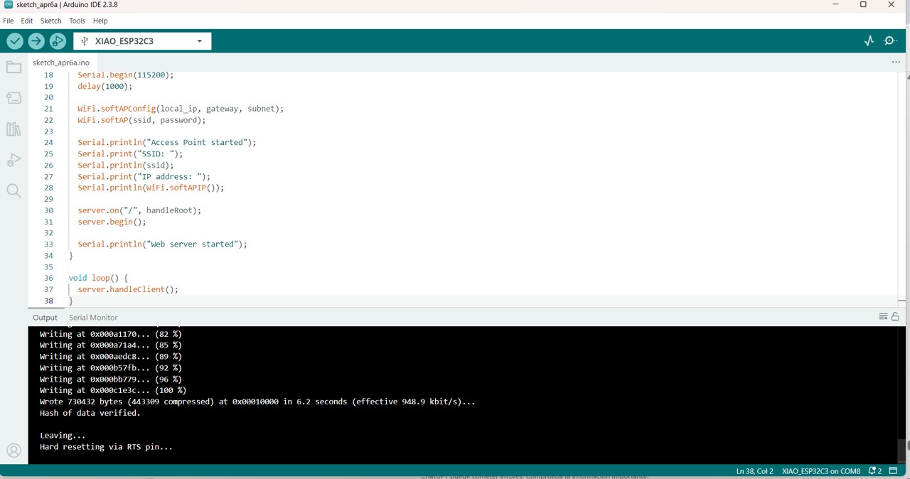
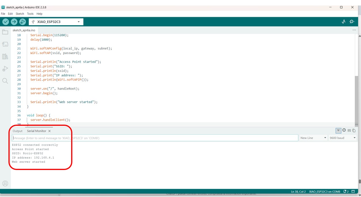
Img 3: Compiling the code on the XIAO ESP32-C3 microcontroller
Then the data for network configuration appeared in serial.
Network configuration
SSID: Rocio-ESP32
Password: 12345678
IP address: 192.168.4.1
Img 4: Shows the correct connection of the XIAO ESP32-C3 to the local network in the serial monitor
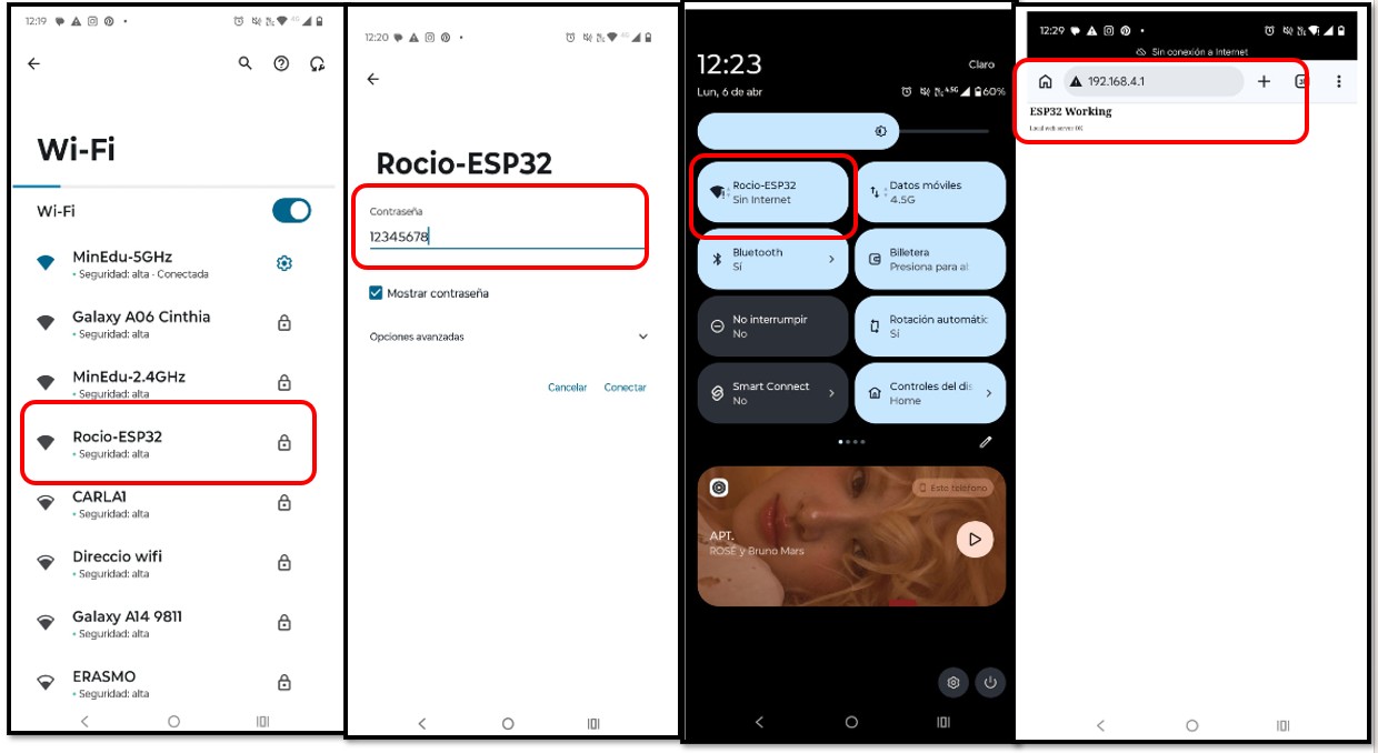
This configuration makes it possible to establish a local network without the need for internet, where the ESP32 functions as a router. The protocol used was: HTTP (HyperText Transfer Protocol). To do this, the WiFi connection is searched for on the mobile phone, in my case with the name Rocio-ESP32, then the password is entered, and we see that we are connected to the WiFi of our microcontroller. It will appear without an internet connection because it is a local connection and not a network connection. Then in the browser we enter the IP address and a web page will appear where we can add buttons to send commands to our board.
Img 5: On the mobile phone the WiFi with the name Rocio-ESP32 is searched for, the password is entered, and the IP address is searched
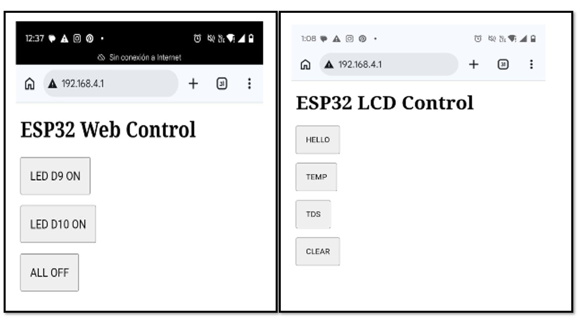
The ESP32 interprets the requests sent from the browser, for example: turn on LED D9, LED D10, turn everything off, or in the case of the LCD screen connection, make the screen say Hello, Temp, TDS, Clear. Each route represents a specific action within the system.
Img 6: Shows the buttons created for the web page to give command orders
In the case of turning the microcontroller board LEDs on and off, I used this code generated by ChatGPT.
This week I also worked with communication protocols to develop a data exchange system between devices using MQTT. The process was carried out progressively, starting with basic software tests and advancing toward communication between microcontrollers.
Procedure:
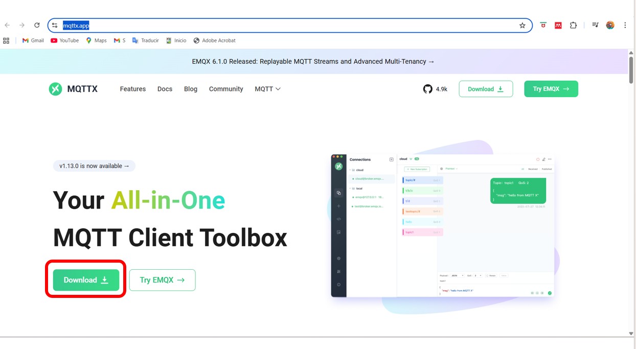
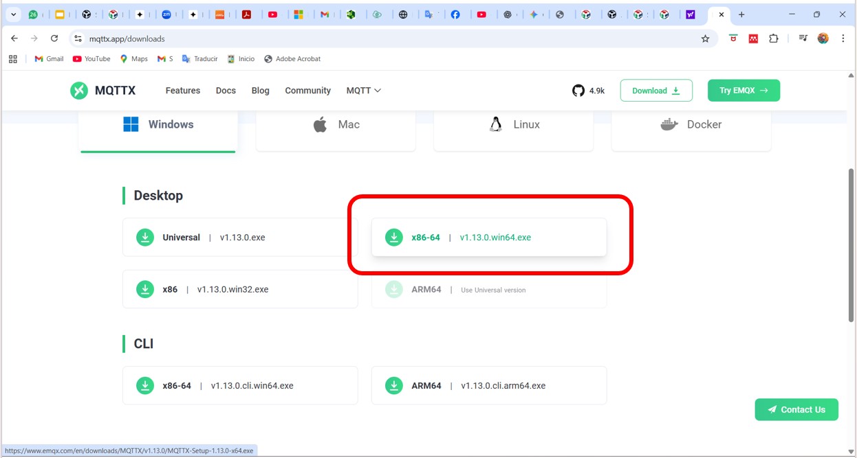
I installed MQTTX on my computer, you can download it here: MQTTX
Img 7: Website where you can download MQTTX
Img 8: In my case I downloaded this X86-64 version
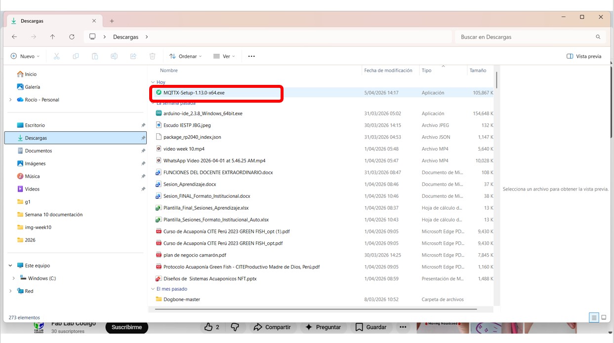
Img 9: I open MQTTX from downloads and start the installation
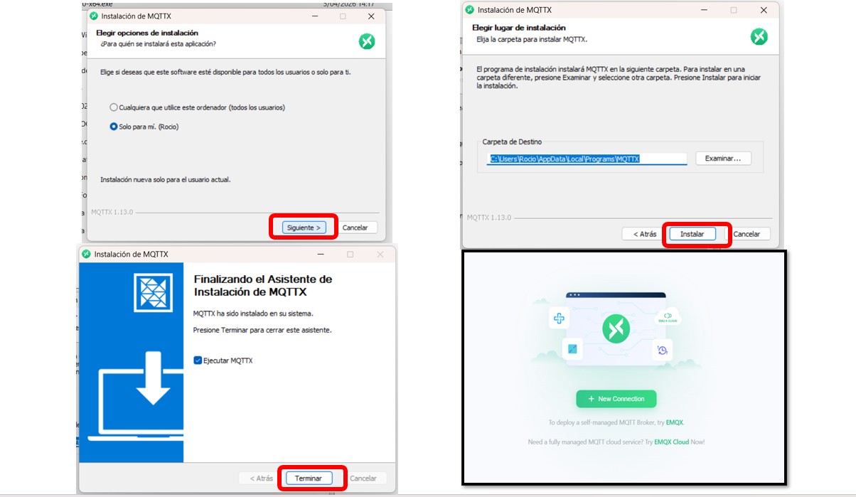
Img 10: I perform the installation
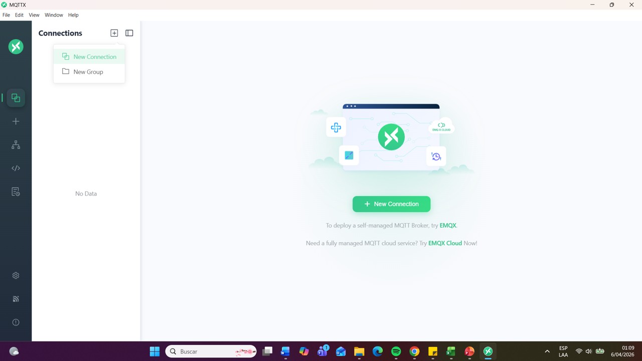
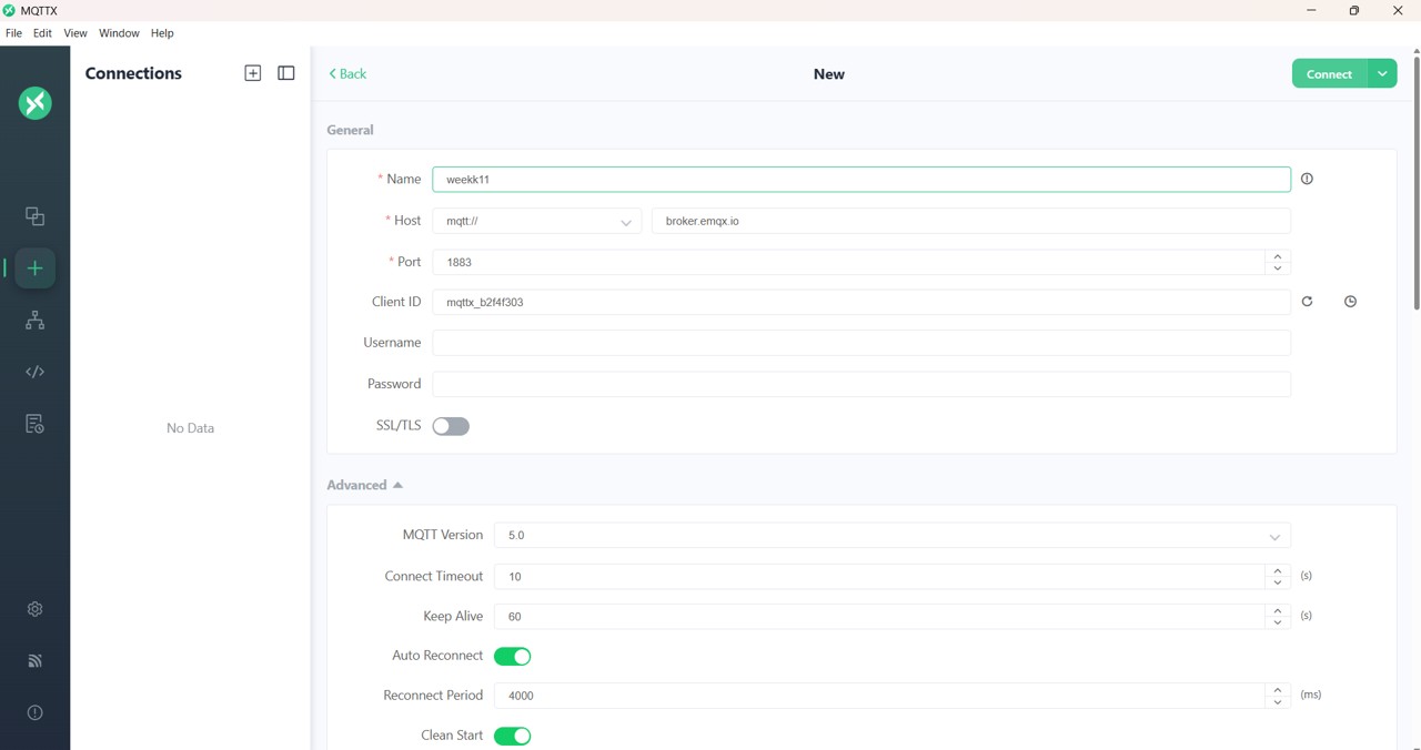
Img 11: I create a new connection in the MQTTX interface
I configured a connection with:
Host: broker.emqx.io
Port: 1883
User: admin
Password: public
Img 12: Connection configuration and topic creation
I verified the successful connection to the broker.
Test 1: MQTTX as publisher and subscriber
In this first stage I performed tests using only MQTTX to understand the operation of the protocol.
Procedure:
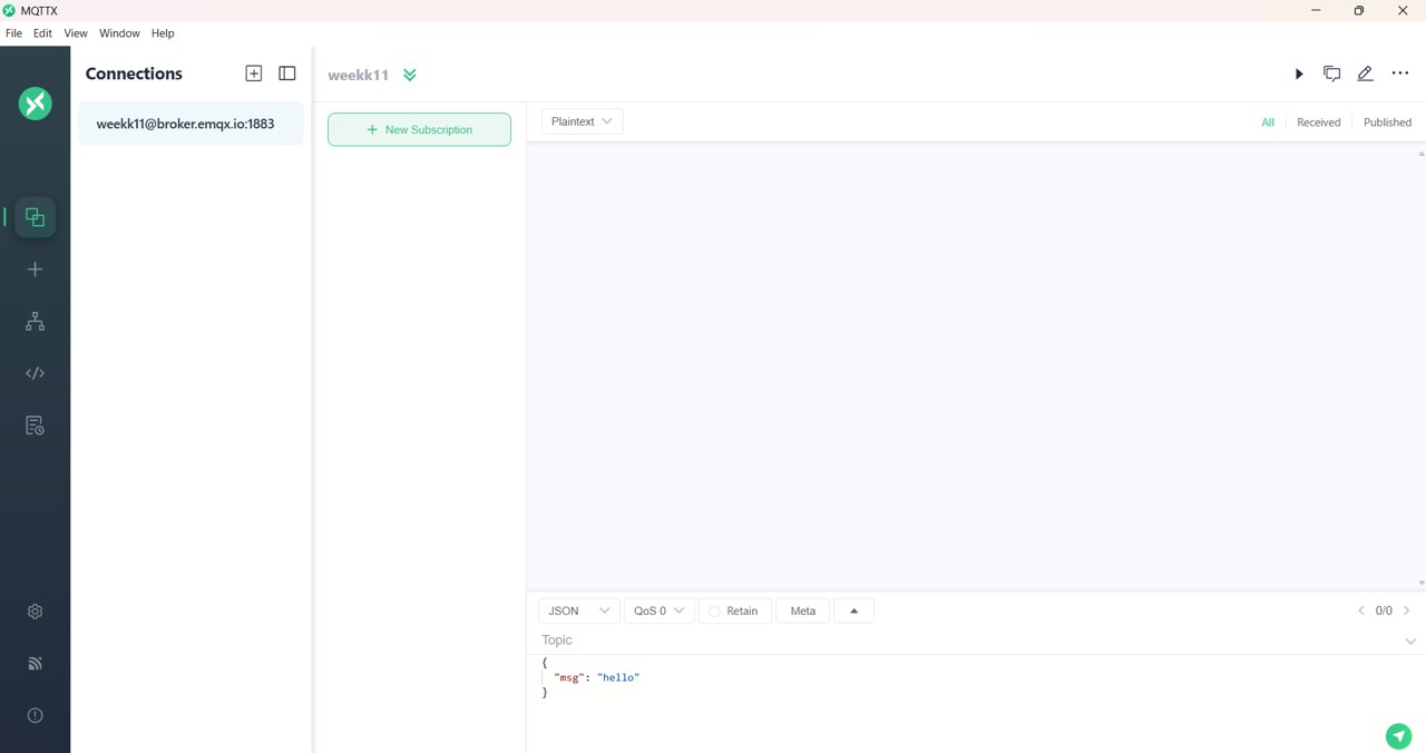
I created two connections inside MQTTX:
One as publisher
Another as subscriber
I defined the topic:
fabacademy/rocio/test
I subscribed to the topic from one connection.
In the other connection I sent messages such as: hello
Img 13: I subscribe to the same created topic
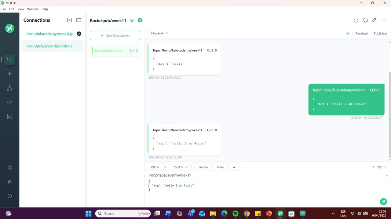
Img 14: I run tests as publisher and subscriber and everything works great
Result: The messages were received correctly in real time within MQTTX.
Learning:
I understood the operation of the publish/subscribe model, where:
the message is not sent directly between devices
the broker acts as an intermediary
Test 2: MQTTX → XIAO ESP32-C3 + LCD
In this stage I integrated hardware into the system, using my XIAO ESP32-C3 board together with an LCD screen. For this part I reviewed teacher Ulises' video, you can check it here: Ulises video
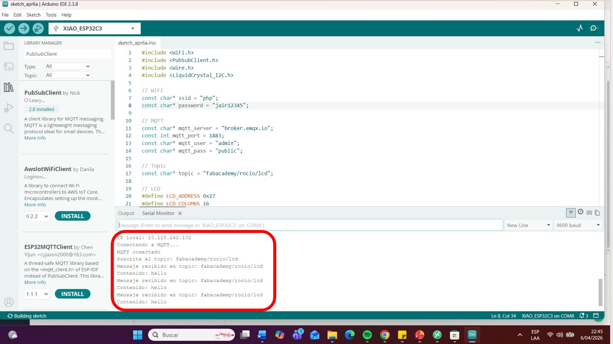
Img 15: Compiling the code on the ESP32-C3 microcontroller
Img 16: The correct connection can be seen in the serial monitor
I used the topic:
fabacademy/rocio/lcd
From MQTTX I sent messages.
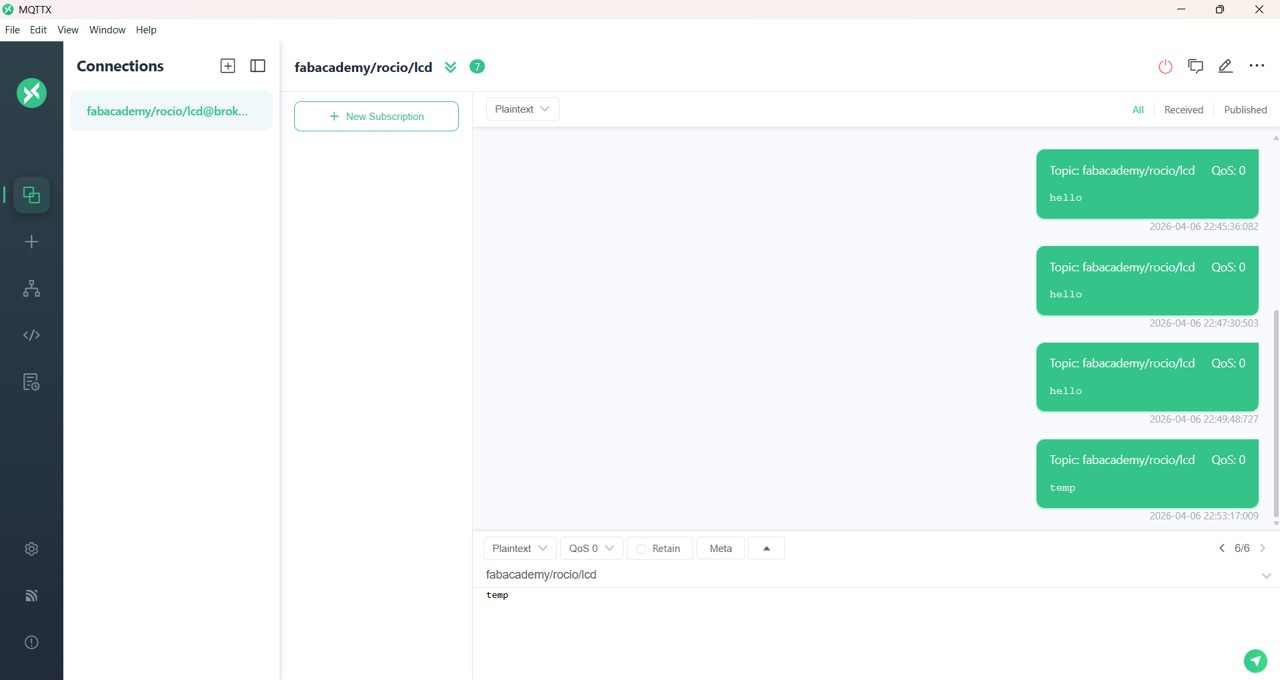
Img 17: I run communication tests in MQTTX, it can be seen that the messages sent from MQTTX appear in the serial monitor of my ESP32-C3 and the message also appears on the LCD
Result:
The ESP32 correctly received the messages
The data was displayed on the LCD screen in real time
Video 5: Test of sending a message in MQTTX and it is shown on the LCD connected to my microcontroller
Img 18: Understanding how MQTTX communication works
Learning:
I learned to integrate:
wireless communication
data processing
hardware visualization
Test 3: Communication between two boards (my own nodes)
In this stage I implemented communication between two microcontrollers using MQTT:
ESP32-WROOM-32 (as sender)
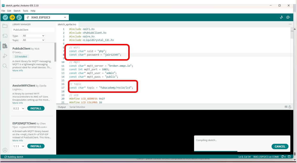
For this I asked ChatGPT for the code and it gave me this:
#include <WiFi.h>
#include <PubSubClient.h>

// ====== DATOS WIFI ======
const char* ssid = "php";
const char* password = "jair12345";

// ====== DATOS MQTT ======
const char* mqtt_server = "broker.emqx.io";
const int mqtt_port = 1883;
const char* topic_pub = "fabacademy/rocio/lcd";

WiFiClient espClient;
PubSubClient client(espClient);

void conectarWiFi() {
  Serial.print("Conectando a WiFi");
  WiFi.begin(ssid, password);

  while (WiFi.status() != WL_CONNECTED) {
    delay(500);
    Serial.print(".");
  }

  Serial.println();
  Serial.println("WiFi conectado");
  Serial.print("IP: ");
  Serial.println(WiFi.localIP());
}

void conectarMQTT() {
  while (!client.connected()) {
    Serial.print("Conectando a MQTT...");

    String clientId = "ESP32_Publicador_";
    clientId += String((uint32_t)ESP.getEfuseMac(), HEX);

    if (client.connect(clientId.c_str())) {
      Serial.println(" conectado");
      Serial.print("Publicando en topic: ");
      Serial.println(topic_pub);
      Serial.println("Escribe un mensaje en el Monitor Serial y presiona Enter");
    } else {
      Serial.print(" fallo, rc=");
      Serial.print(client.state());
      Serial.println(" reintentando en 2 segundos");
      delay(2000);
    }
  }
}

void setup() {
  Serial.begin(115200);
  conectarWiFi();

  client.setServer(mqtt_server, mqtt_port);
}

void loop() {
  if (!client.connected()) {
    conectarMQTT();
  }
  client.loop();

  if (Serial.available()) {
    String mensaje = Serial.readStringUntil('\n');
    mensaje.trim();

    if (mensaje.length() > 0) {
      if (client.publish(topic_pub, mensaje.c_str())) {
        Serial.print("Mensaje enviado: ");
        Serial.println(mensaje);
      } else {
        Serial.println("Error al publicar");
      }
    }
  }
}
Board designed by me with XIAO ESP32-C3 (as receiver with LCD)
For this I asked ChatGPT for the code and it gave me this:
#include <WiFi.h>
#include <PubSubClient.h>
#include <Wire.h>
#include <LiquidCrystal_I2C.h>

// ====== DATOS WIFI ======
const char* ssid = "php";
const char* password = "jair12345";

// ====== DATOS MQTT ======
const char* mqtt_server = "broker.emqx.io";
const int mqtt_port = 1883;
const char* topic_sub = "fabacademy/rocio/lcd";

// Direction and size
#define LCD_ADDRESS 0x27
#define LCD_COLUMNS 16
#define LCD_ROWS 2

// ====== LCD I2C ======
// Correct constructor for New-LiquidCrystal
LiquidCrystal_I2C lcd(LCD_ADDRESS, 2, 1, 0, 4, 5, 6, 7, 3, POSITIVE);

WiFiClient espClient;
PubSubClient client(espClient);

void mostrarEnLCD(String texto) {
  lcd.clear();

  // First line
  lcd.setCursor(0, 0);
  lcd.print("Msg MQTT:");

  // Second line: maximum 16 visible characters
  lcd.setCursor(0, 1);
  if (texto.length() <= 16) {
    lcd.print(texto);
  } else {
    lcd.print(texto.substring(0, 16));
  }
}

void callback(char* topic, byte* payload, unsigned int length) {
  String mensaje = "";

  for (unsigned int i = 0; i < length; i++) {
    mensaje += (char)payload[i];
  }

  Serial.println("Mensaje recibido:");
  Serial.print("Topic: ");
  Serial.println(topic);
  Serial.print("Contenido: ");
  Serial.println(mensaje);

  mostrarEnLCD(mensaje);
}

void conectarWiFi() {
  Serial.print("Conectando a WiFi");
  WiFi.begin(ssid, password);

  while (WiFi.status() != WL_CONNECTED) {
    delay(500);
    Serial.print(".");
  }

  Serial.println();
  Serial.println("WiFi conectado");
  Serial.print("IP: ");
  Serial.println(WiFi.localIP());
}

void conectarMQTT() {
  while (!client.connected()) {
    Serial.print("Conectando a MQTT...");

    String clientId = "ESP32_Receptor_";
    clientId += String((uint32_t)ESP.getEfuseMac(), HEX);

    if (client.connect(clientId.c_str())) {
      Serial.println(" conectado");
      client.subscribe(topic_sub);
      Serial.print("Suscrito a: ");
      Serial.println(topic_sub);

      lcd.clear();
      lcd.setCursor(0, 0);
      lcd.print("MQTT conectado");
      lcd.setCursor(0, 1);
      lcd.print("Esperando...");
    } else {
      Serial.print(" fallo, rc=");
      Serial.print(client.state());
      Serial.println(" reintentando en 2 segundos");
      delay(2000);
    }
  }
}

void setup() {
  Serial.begin(115200);

  // Correct initialization for your LCD and your XIAO ESP32-C3
  Wire.begin(6, 7);
  lcd.begin(LCD_COLUMNS, LCD_ROWS);
  lcd.backlight();
  lcd.clear();
  lcd.setCursor(0, 0);
  lcd.print("Iniciando...");

  conectarWiFi();

  client.setServer(mqtt_server, mqtt_port);
  client.setCallback(callback);
}

void loop() {
  if (!client.connected()) {
    conectarMQTT();
  }
  client.loop();
}
This test was carried out using two different sketches in Arduino IDE, simulating two independent nodes.
System architecture
ESP32-WROOM-32 → Publisher
For this I asked ChatGPT to give me the code and I used this, I only had to change the WiFi part, with my mobile phone WiFi.
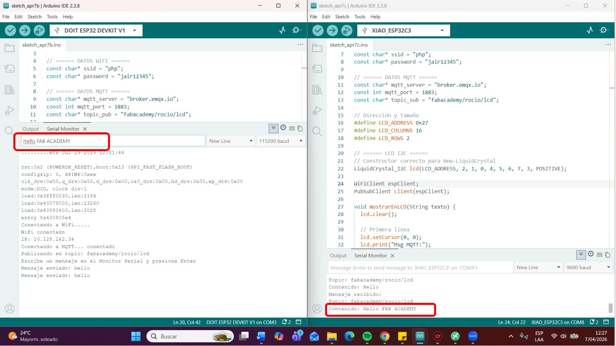
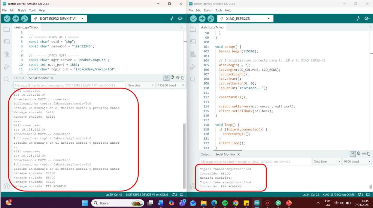
Img 19: Sending messages from the serial monitor of the ESP32-WROOM-32 and receiving them in the serial monitor of the ESP32-C3
Img 20: Successful connection can be seen in the serial monitors through MQTTX
XIAO ESP32-C3 → Subscriber + LCD
Both devices were connected to the same MQTT broker.
Topic used
fabacademy/rocio/lcd
Communication flow
The ESP32-WROOM-32 sends a message from the serial monitor
The message is published to the broker
The XIAO ESP32-C3 is subscribed to the topic
The message is received
It is processed and shown on the LCD screen
Tests performed
Sending from ESP32-WROOM-32
Message sent from the serial monitor: Hello FAB ACADEMY
Result: The message was correctly received by the XIAO ESP32-C3.
Visualization on LCD
The received message was shown on the LCD screen connected to the XIAO.
Result: Correct real-time visualization.
Video 6: Demonstration of the WiFi connection of the ESP32-WROOM-32 and the XIAO ESP32-C3, and the messages are displayed on the serial monitor and also on the LCD connected to the XIAO
Troubleshooting and Debugging
During the development of this assignment, several communication issues were encountered while establishing the wireless connection between the ESP32 boards, the MQTT broker, and the LCD display. Different debugging strategies were applied using the Arduino Serial Monitor, MQTTX, and real-time communication tests.
WiFi Connection Issues
One of the first challenges was establishing a stable WiFi connection. Connection attempts were monitored through the Serial Monitor, allowing verification of the network credentials and connection status. After correcting the network configuration, the ESP32 successfully connected to the WiFi network.
MQTT Broker Communication Problems
During the MQTT implementation, communication was not initially established due to configuration errors. The broker address, communication port, and connection status were verified through serial debugging messages. Once the parameters were corrected, the devices successfully connected and exchanged information through the MQTT broker.
LCD Communication Verification
While integrating the LCD display, the received messages were not initially shown correctly. The issue was traced to the I2C configuration and address assignment. After verifying the SDA and SCL connections and confirming the correct I2C address, the LCD displayed the transmitted messages successfully.
Data Transfer Validation
Several tests were performed to verify successful communication between devices. Messages were published using MQTTX and received by the XIAO ESP32-C3. The transmitted data was displayed on the LCD screen in real time, confirming that the communication chain was functioning correctly.
WiFi connection verified through the Serial Monitor.
MQTT communication verified using MQTTX.
Message reception verified on the LCD display.
Publisher and subscriber successfully shared the same MQTT topic.
Real-time communication between devices was confirmed.
The following communication chain was successfully validated:
This assignment allowed me to better understand how communication protocols are used in embedded systems and IoT applications. I learned how MQTT uses a publish/subscribe architecture to exchange information between devices through a broker and how WiFi connectivity enables real-time communication.
I also learned the importance of debugging communication systems using serial monitoring tools, verifying network configurations, checking MQTT topics, and validating data transmission step by step. These experiences provided a solid foundation for implementing remote monitoring and communication systems in future IoT projects.
CONCLUSIONS:
During week 11, it was possible to implement a communication system using the MQTT protocol, progressing from basic software tests to interaction between microcontrollers. Through this process, it was verified that the use of a broker allows devices to be decoupled, facilitating communication between nodes without the need for a direct connection between them.
The use of the publish/subscribe model made it possible to organize data transmission efficiently, demonstrating that multiple devices can send and receive information in real time through the same channel structured by topics.
Likewise, it was validated that ESP32 boards can be easily integrated into network systems, allowing not only the reception of data, but also its processing and visualization through output devices such as the LCD screen.
Finally, the implementation of communication between two microcontrollers using different sketches showed that it is possible to simulate distributed networks and build functional IoT systems even in controlled testing environments.
Reflection
During this week, the learning process was progressive and practical, beginning with understanding the operation of MQTT through tests in MQTTX, which made it possible to clearly understand the communication flow between publisher, broker, and subscriber.
One of the most important aspects was recognizing the difference between protocols such as HTTP and MQTT, understanding that the latter is specifically designed for IoT systems due to its lightness and efficiency in data transmission.
The integration of hardware represented an additional challenge, especially in WiFi configuration, library management, and the correct interpretation of received messages. However, overcoming these challenges made it possible to better understand the relationship between software and hardware in embedded systems.
The experience of working with two different boards and using different sketches helped visualize how distributed systems work in practice, reinforcing the idea that each device can act as an independent node within a network.
In general, this week made it possible to move from a theoretical understanding of network communication to a real implementation, strengthening skills in programming, problem solving, and IoT system design.
Files & Downloads
This section includes the files used for the networking and communication assignment, including the code for transmitting and receiving data, PCB design files, and device documentation. The communication tests and results are documented above.