Assignment requirements
Group assignment
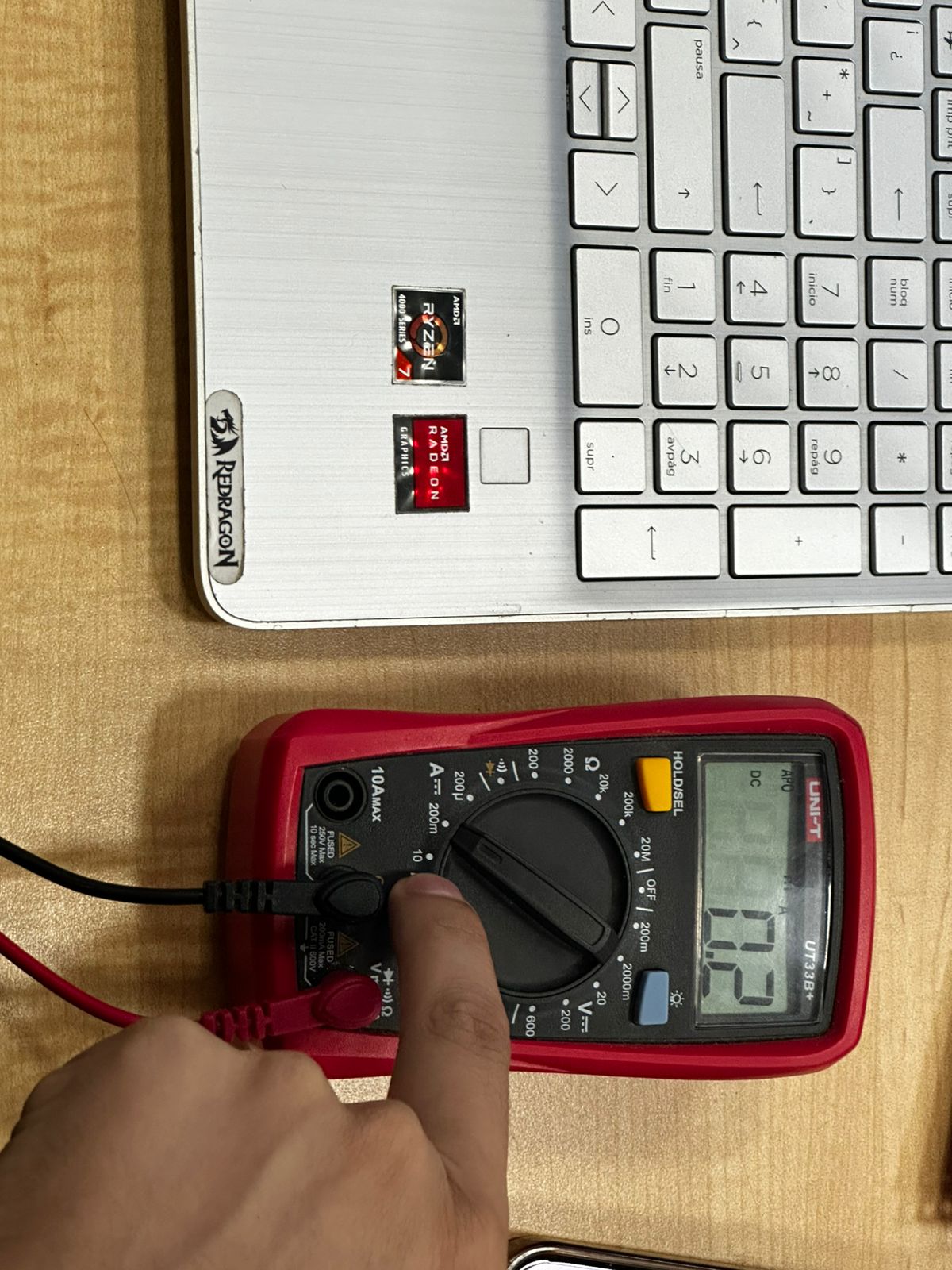
- Measure the power consumption of an output device
- Document your work on the group work page and reflect on your individual page what you learned
Individual assignment
- Measure something: add a sensor to a microcontroller board that you have designed and read it
Progress status
Test an output device and measure power consumption
Measure the power consumption of an output device
Upload source files
1) Introduction
Closing gaps
- Learn about output devices
- Interact more with Arduino IDE
- Discuss the group project
- Develop the individual project
2) Group assignment 1 - Test an output device
For more details visit Fab Lab Peru Week 10 Group assignment
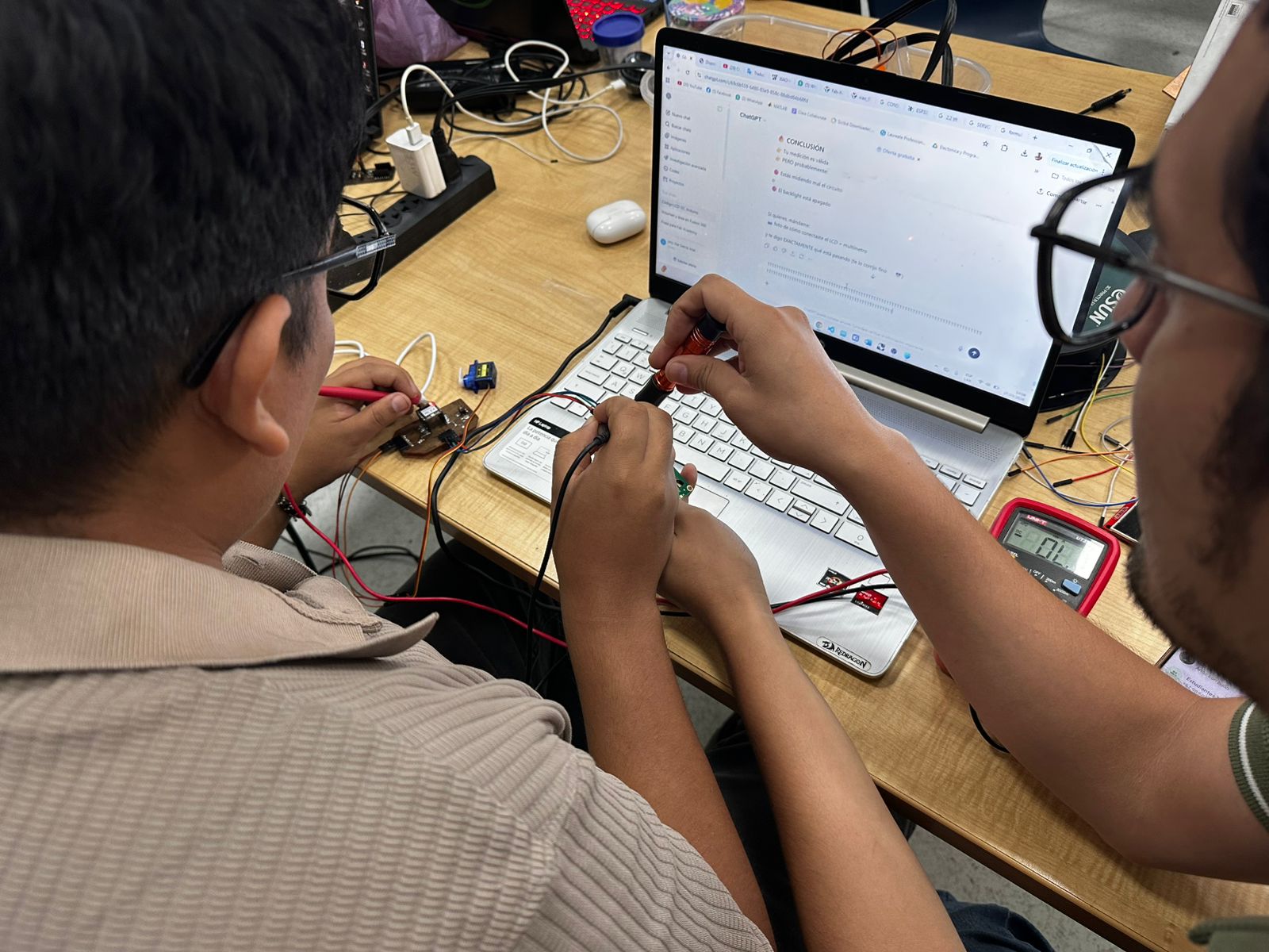
Problems
Designed microcontroller board doesn't work
Review connections
Step 1 - Protoboard
Mesasure something with the microcontroller RP2040
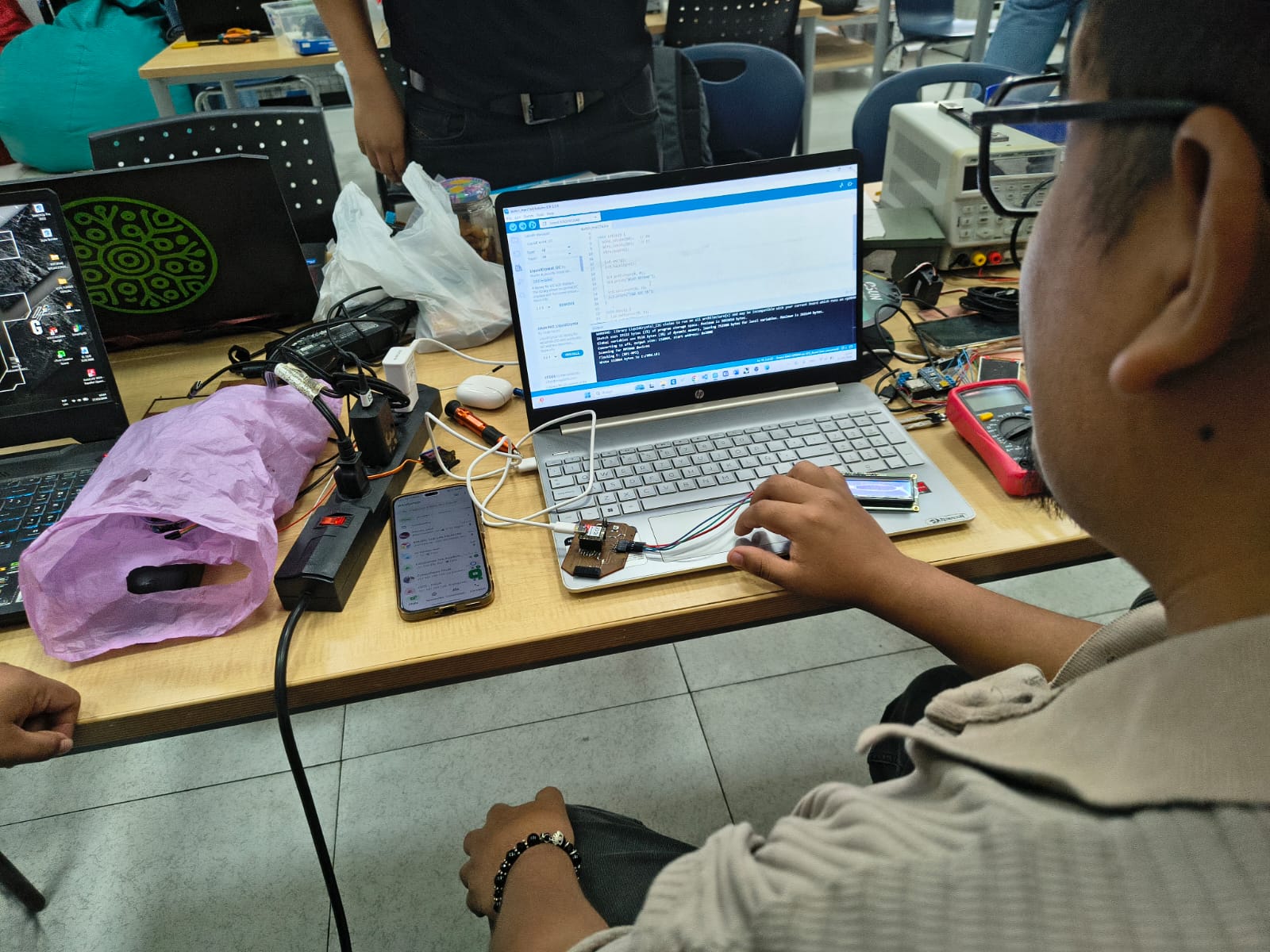
// Programming LCD + I2Cing three TCRT5000L reflective optical sensor
// Board: Seeed Studio XIAO RP 2040
#include
#include
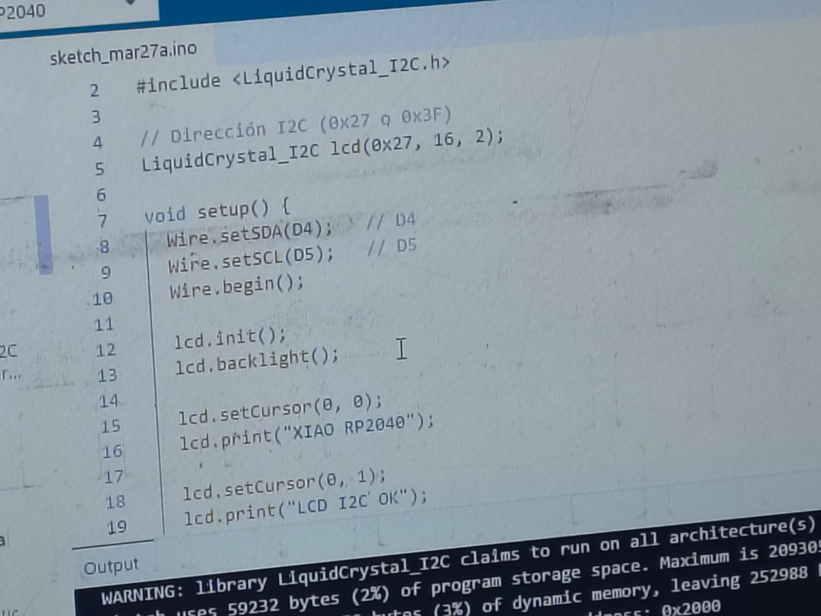
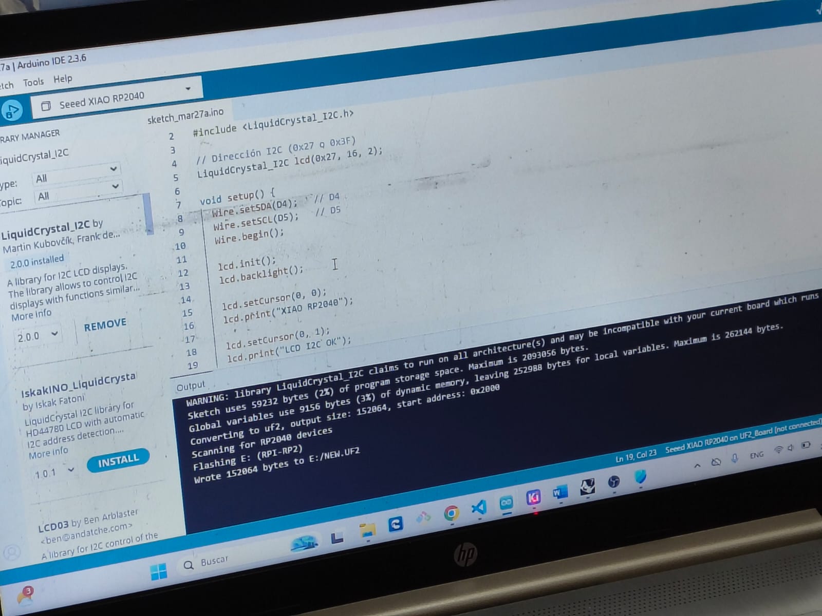
// Set the LCD address to 0x27 for a 16 chars and 2 line display
// If 0x27 doesn't work, try 0x3F. You may need an I2C scanner.
LiquidCrystal_I2C lcd(0x27, 16, 2);
void setup() {
Wire.setSDA(D4); //D4
Wire.setSCL(D5); //D5
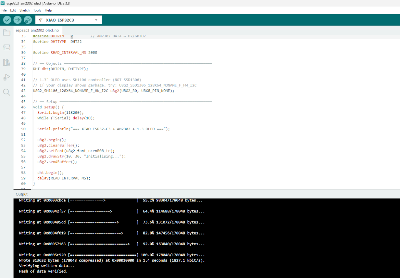
// Initialize the I2C bus
Wire.begin();
// Initialize the LCD screen
lcd.init();
// Turn on the backlight
lcd.backlight();
// Set the cursor to column 0, row 0 (0-indexed)
lcd.setCursor(0, 0);
// Print a message to the LCD.
lcd.print("Fab Academy");
// Set the cursor to column 0, row 1
lcd.setCursor(0, 1);
lcd.print("Fab Academy Peru");
}
void loop() {
// Main loop is empty, display updates once in setup
}
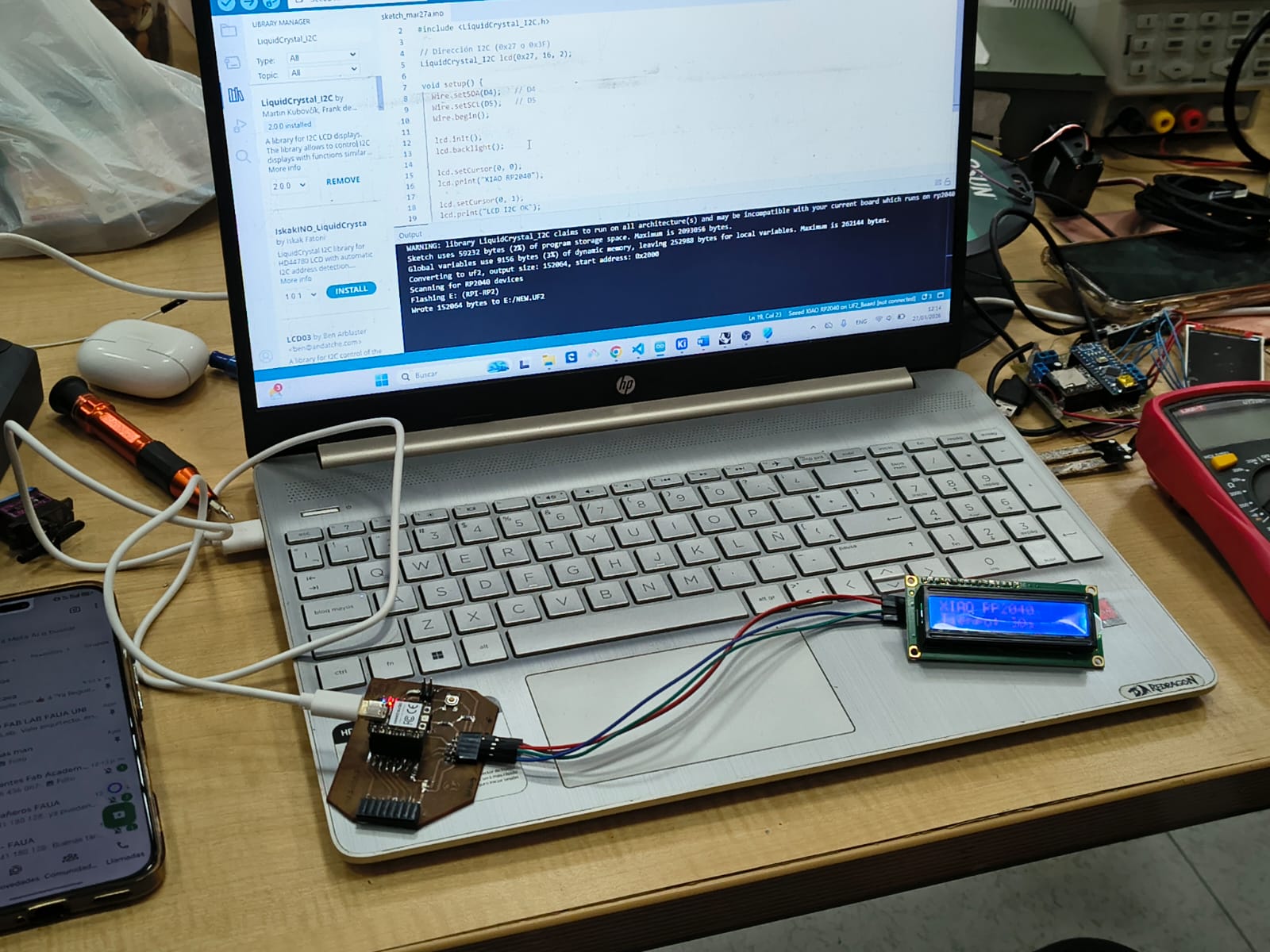
Video demonstration
3) Individual assigment
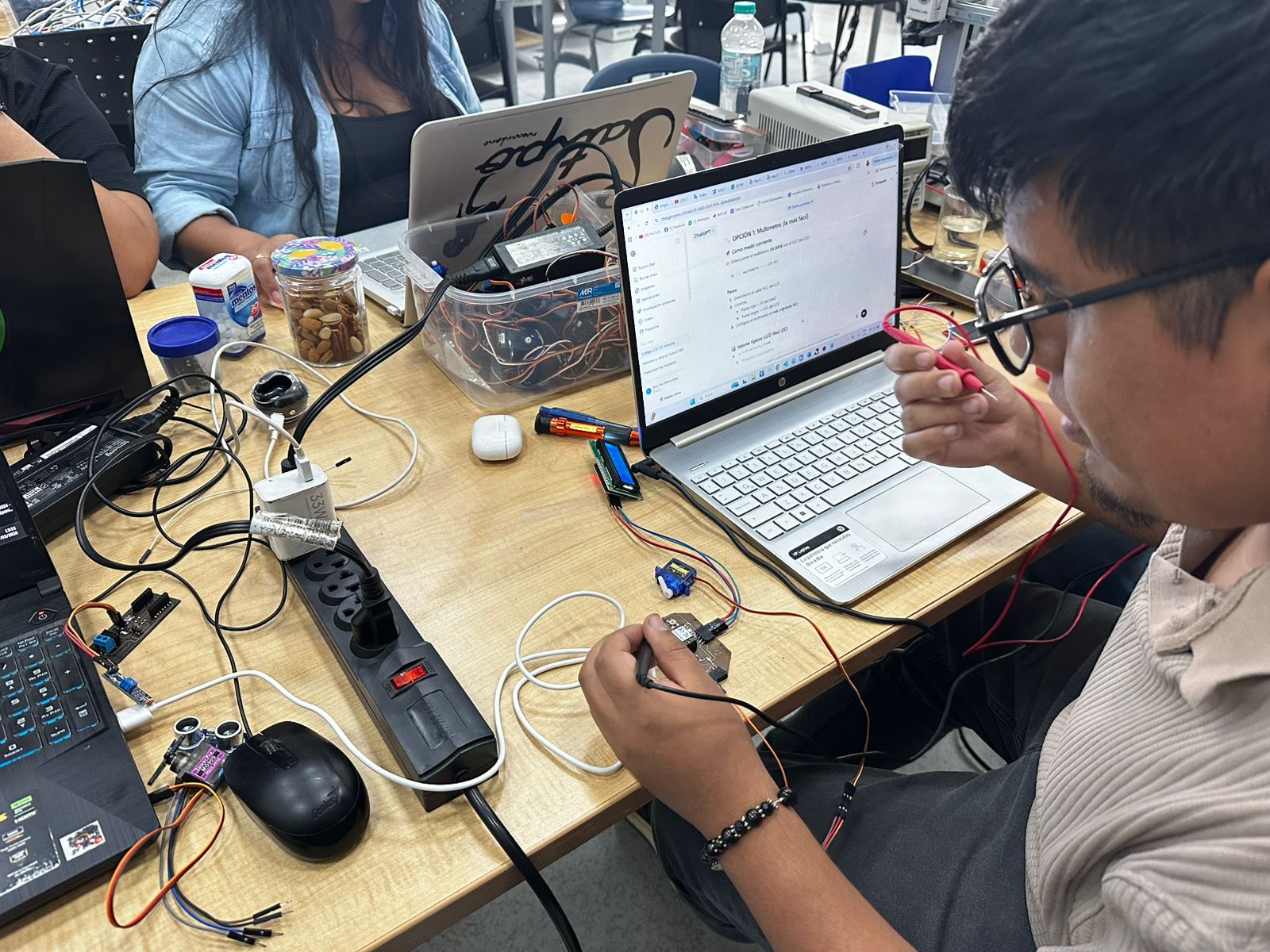
Problems
Designed microcontroller board doesn't work
Posible solution - make a new board
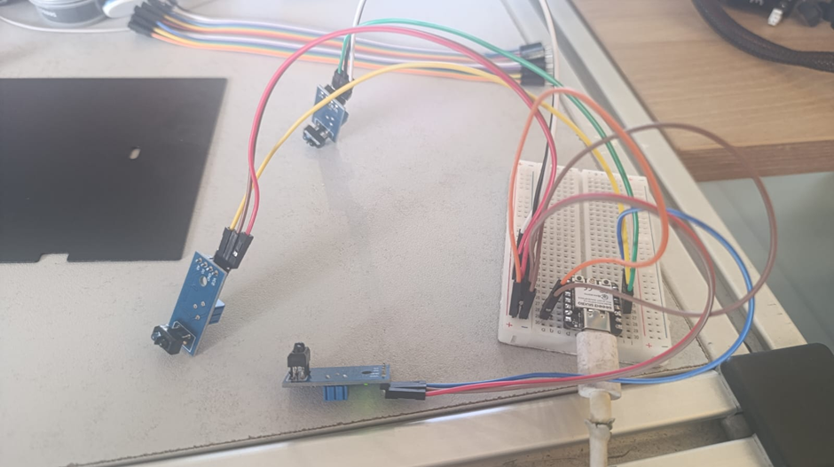
Step 1 - Protoboard
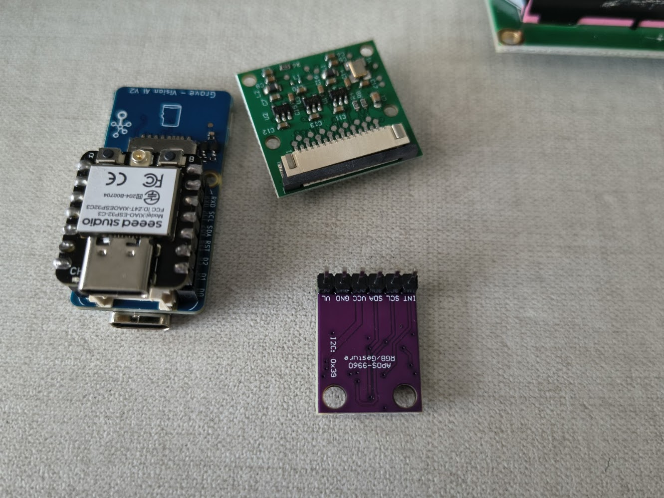
Mesasure something with the microcontroller Xiao ESP32 C3
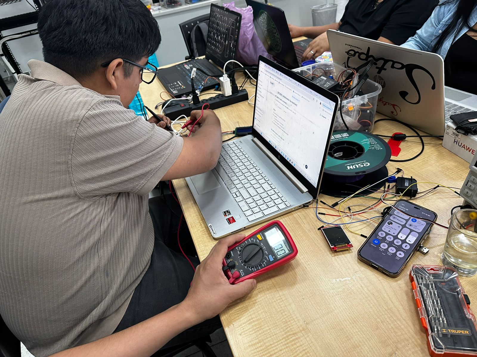
Step 2 - Repeat with a new board
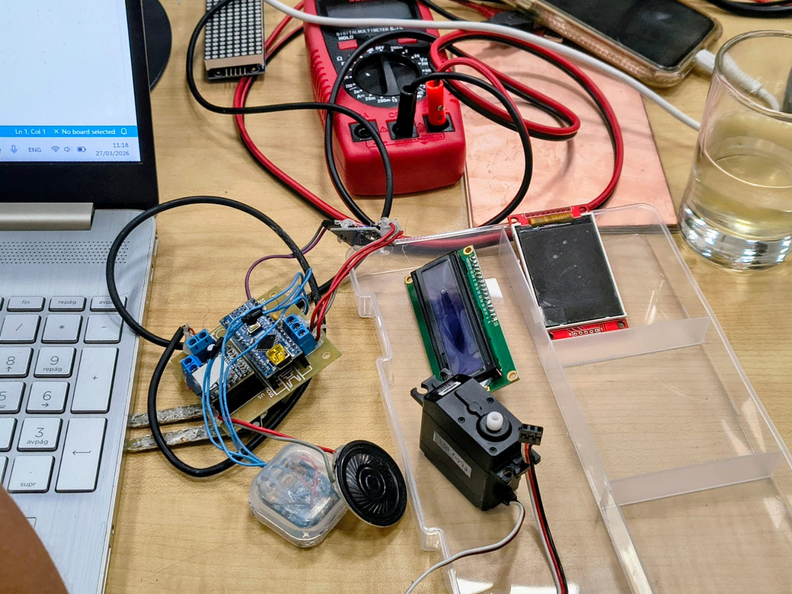
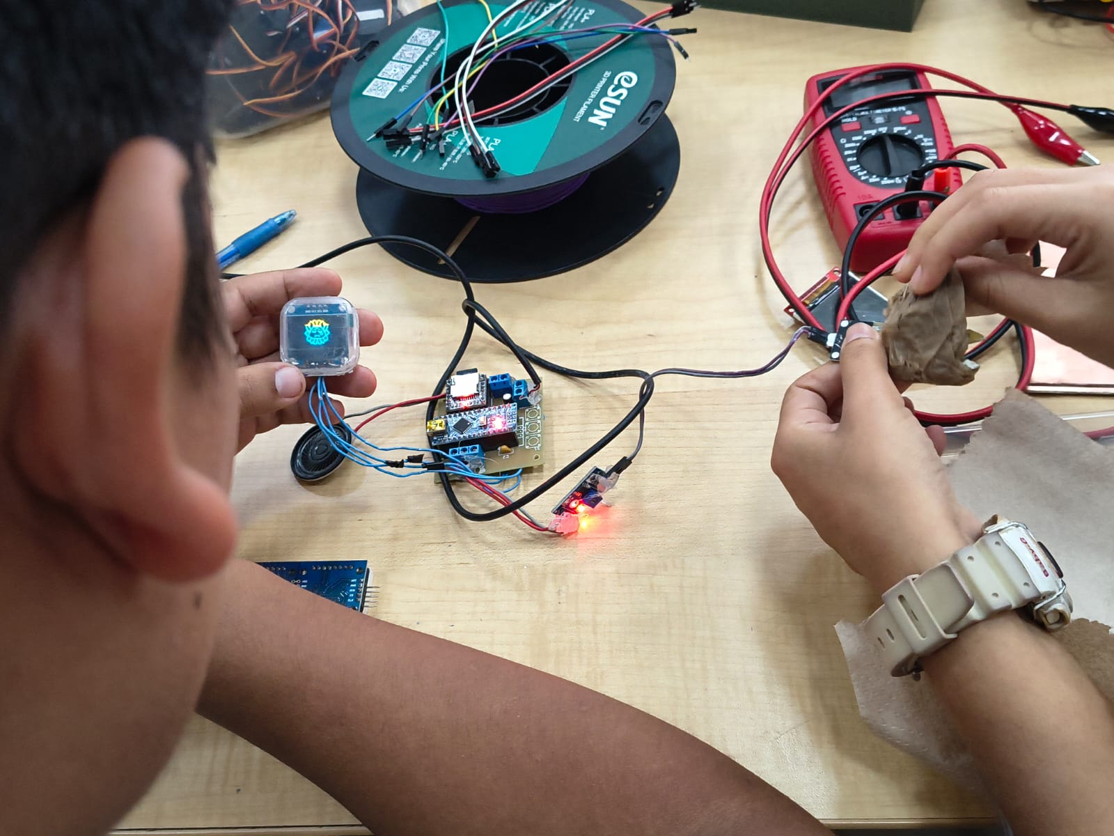
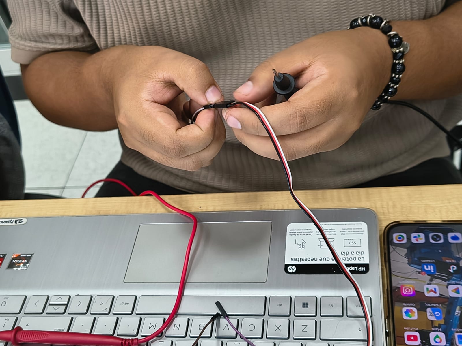
Measure and test devices using a multimeter or an oscilloscope
// Using three TCRT5000L reflective optical sensor
// Input devices
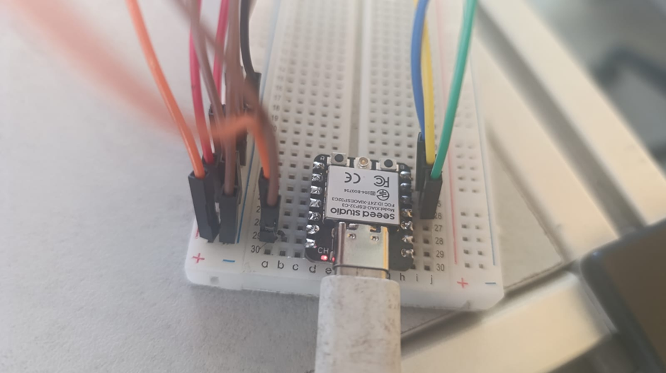
// Board: Seeed Studio XIAO ESP 32 C3
#define sensor1 D6 // cambia al GPIO/pin que uses
#define sensor2 D5 // cambia al GPIO/pin que uses
#define sensor3 D4 // cambia al GPIO/pin que uses
void setup() {
Serial.begin(115200);
pinMode(sensor1, INPUT);
pinMode(sensor2, INPUT);
pinMode(sensor3, INPUT);
}
void loop() {
int val1 = digitalRead(sensor1);
int val2 = digitalRead(sensor2);
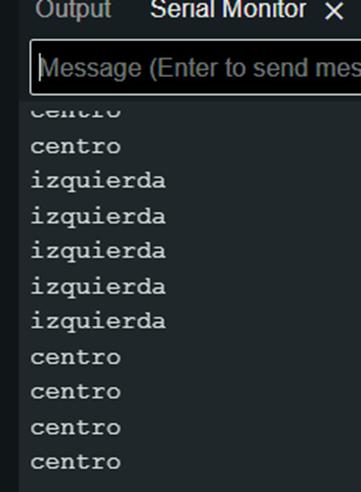
int val3 = digitalRead(sensor3);
if(val1==1){
Serial.println("izquierda");
}
else if(val2==1){
Serial.println("centro");
}
else if(val3==1){
Serial.println("derecha");
}
else{
Serial.println("error");
}
delay(100);
}
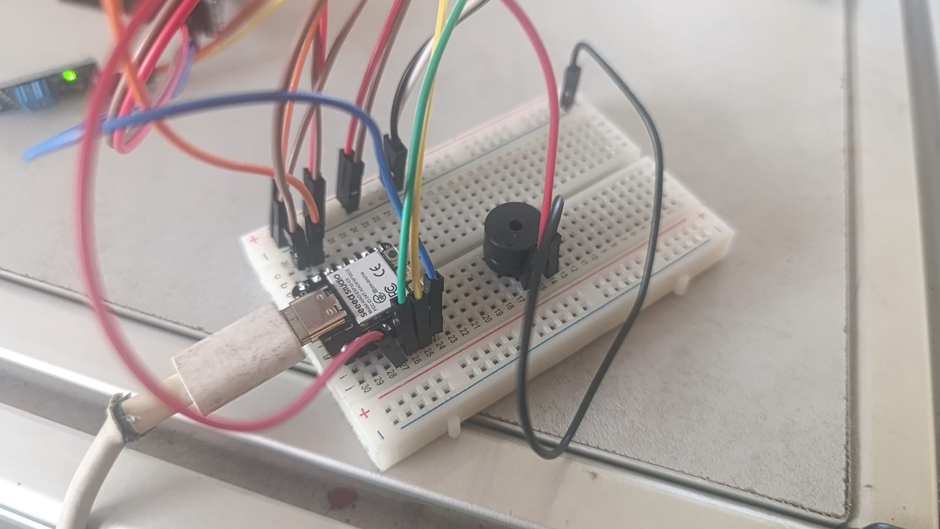
// Using three TCRT5000L reflective optical sensor & buzzer - Center or not
              // Input devices
              // Board: Seeed Studio XIAO ESP 32 C3

              #define sensor1 D6   // cambia al GPIO/pin que uses
              #define sensor2 D5   // cambia al GPIO/pin que uses
              #define sensor3 D4   // cambia al GPIO/pin que uses


              void setup() {
                  Serial.begin(115200);
                  pinMode(sensor1, INPUT);
                  pinMode(sensor2, INPUT);
                  pinMode(sensor3, INPUT);
                  pinMode(D3, OUTPUT);
              }

              void loop() {
                int val1 = digitalRead(sensor1);
                int val2 = digitalRead(sensor2);
                int val3 = digitalRead(sensor3);
                if(val1==1){
                  Serial.println("izquierda");
                    digitalWrite (D3, HIGH);
                    delayMicroseconds (5000);
                    digitalWrite (D3, LOW);
                    delayMicroseconds (100000);
                }
                else if(val2==1){
                  Serial.println("centro");
                }
                else if(val3==1){
                  Serial.println("derecha");
                    digitalWrite (D3, HIGH);
                    delayMicroseconds (5000);
                    digitalWrite (D3, LOW);
                    delayMicroseconds (100000);
                }
                else{
                  Serial.println("error");
                    digitalWrite (D3, HIGH);
                    delayMicroseconds (5000);
                    digitalWrite (D3, LOW);
                    delayMicroseconds (100000);
                }
                delay(100);
              }
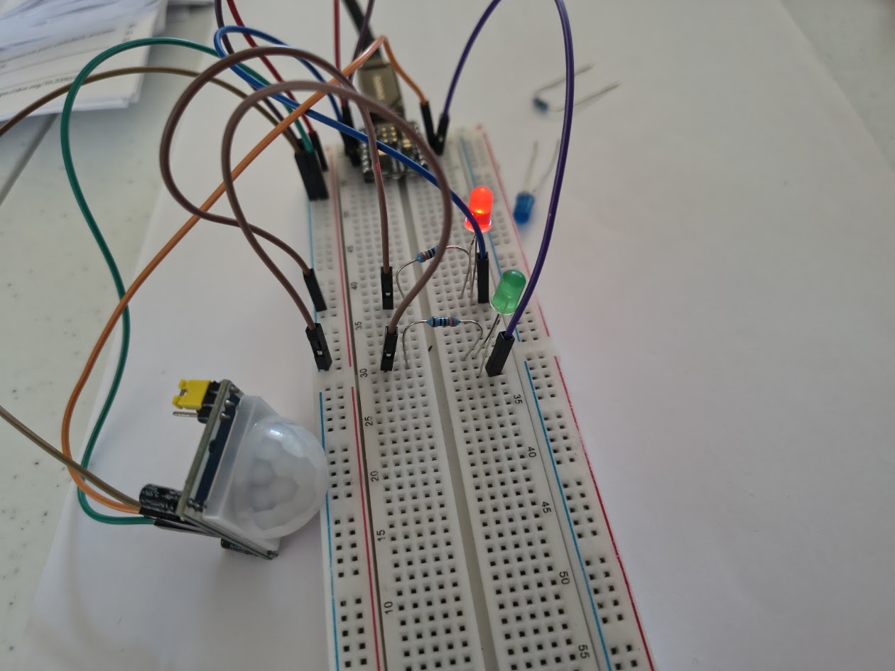
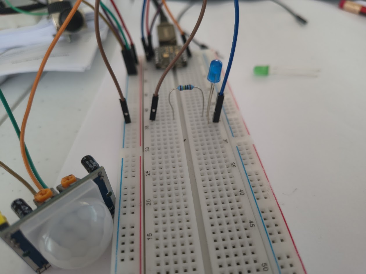
// Using PIR sensor and led for testing
// Input devices
// Board: Seeed Studio XIAO ESP 32 C3
#define PIR_PIN 2
#define LED_PIN 10
#define LED_PIN2 3
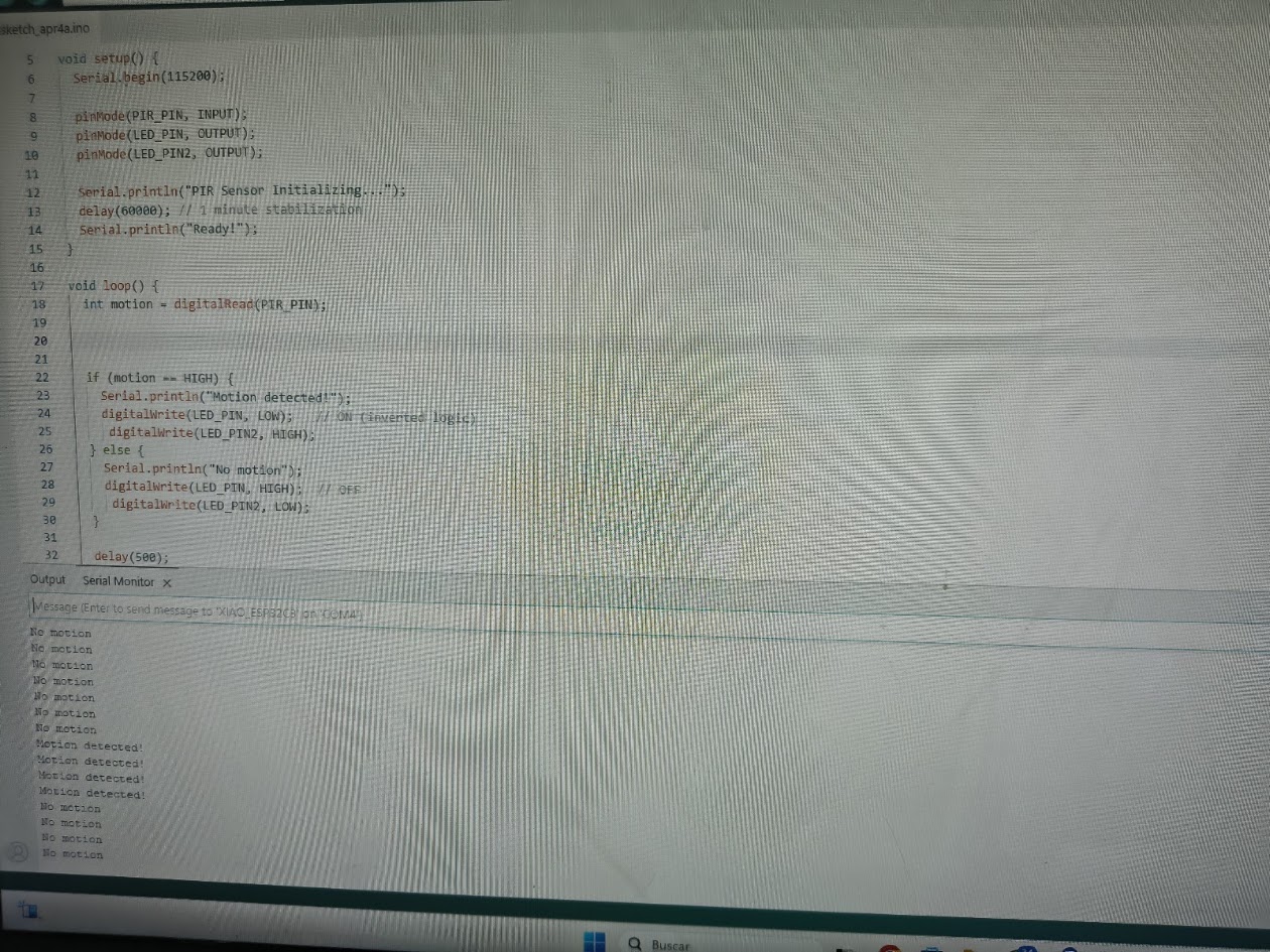
void setup() {
Serial.begin(115200);
pinMode(PIR_PIN, INPUT);
pinMode(LED_PIN, OUTPUT);
pinMode(LED_PIN2, OUTPUT);
Serial.println("PIR Sensor Initializing...");
delay(60000); // 1 minute stabilization
Serial.println("Ready!");
}
void loop() {
int motion = digitalRead(PIR_PIN);
if (motion == HIGH) {
Serial.println("Motion detected!");
digitalWrite(LED_PIN, LOW); // ON (inverted logic)
digitalWrite(LED_PIN2, HIGH);
} else {
Serial.println("No motion");
digitalWrite(LED_PIN, HIGH); // OFF
digitalWrite(LED_PIN2, LOW);
}
delay(500);
}
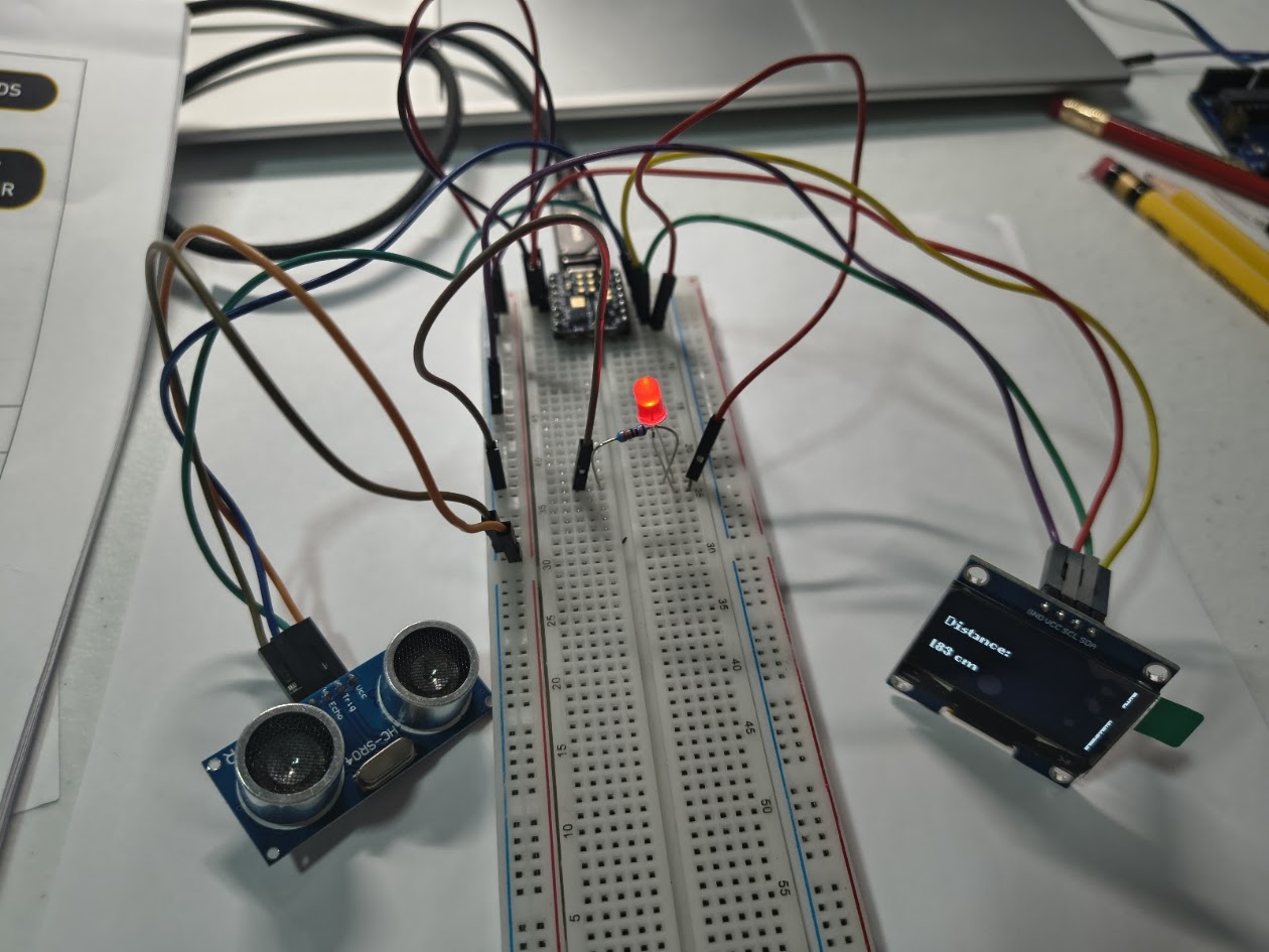
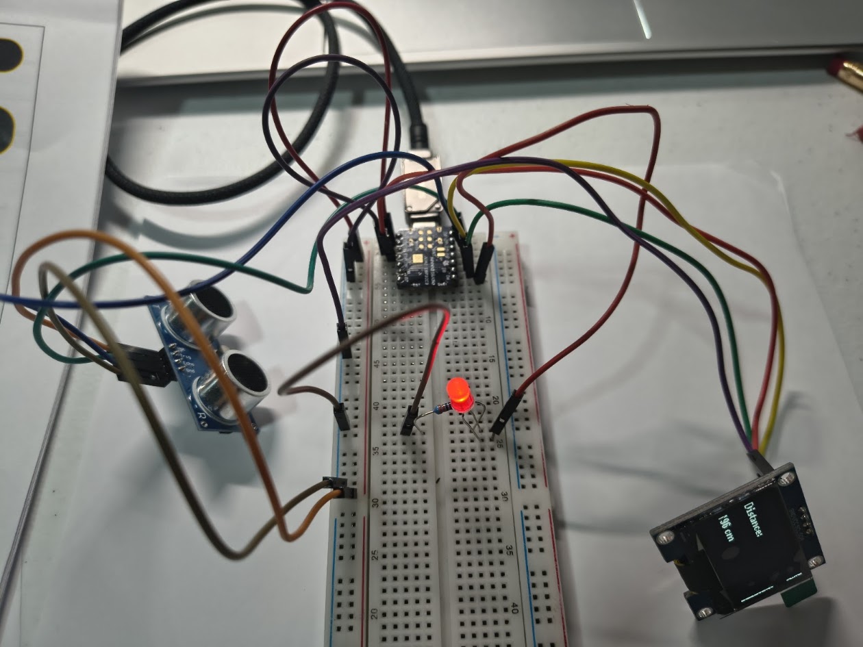
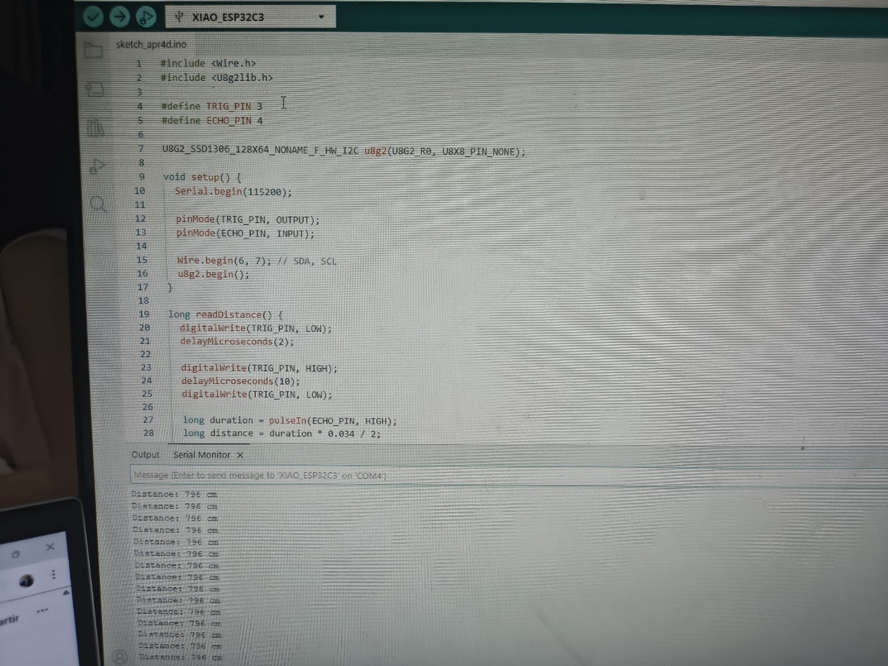
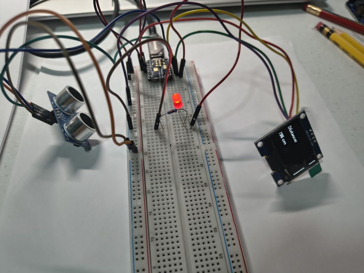
// HC-SR04 sensor & OLED display
              // Input devices
              // Board: Seeed Studio XIAO ESP 32 C3

                  #include
                  #include

                  #define TRIG_PIN 3
                  #define ECHO_PIN 4

                  U8G2_SSD1306_128X64_NONAME_F_HW_I2C u8g2(U8G2_R0, U8X8_PIN_NONE);

                  void setup() {
                    Serial.begin(115200);

                    pinMode(TRIG_PIN, OUTPUT);
                    pinMode(ECHO_PIN, INPUT);

                    Wire.begin(6, 7); // SDA, SCL
                    u8g2.begin();
                  }

                  long readDistance() {
                    digitalWrite(TRIG_PIN, LOW);
                    delayMicroseconds(2);

                    digitalWrite(TRIG_PIN, HIGH);
                    delayMicroseconds(10);
                    digitalWrite(TRIG_PIN, LOW);

                    long duration = pulseIn(ECHO_PIN, HIGH);
                    long distance = duration * 0.034 / 2;

                    return distance;
                  }

                  void loop() {
                    long distance = readDistance();

                    Serial.print("Distance: ");
                    Serial.print(distance);
                    Serial.println(" cm");

                    u8g2.clearBuffer();

                    if (distance < 20) {
                      u8g2.setFont(u8g2_font_logisoso24_tr);
                      u8g2.drawStr(0, 40, "CLOSE!");
                    } else {
                      u8g2.setFont(u8g2_font_ncenB08_tr);
                      u8g2.drawStr(0, 25, "Distance:");

                      char buf[20];
                      sprintf(buf, "%ld cm", distance);
                      u8g2.drawStr(0, 50, buf);
                    }

                    u8g2.sendBuffer();

                    delay(300);
                  }
Video demonstration
3.1) Additional individual assigment
Details
Designed microcontroller board read real
Showed output - serial monitor valuess
Included code
Demostrate that its works
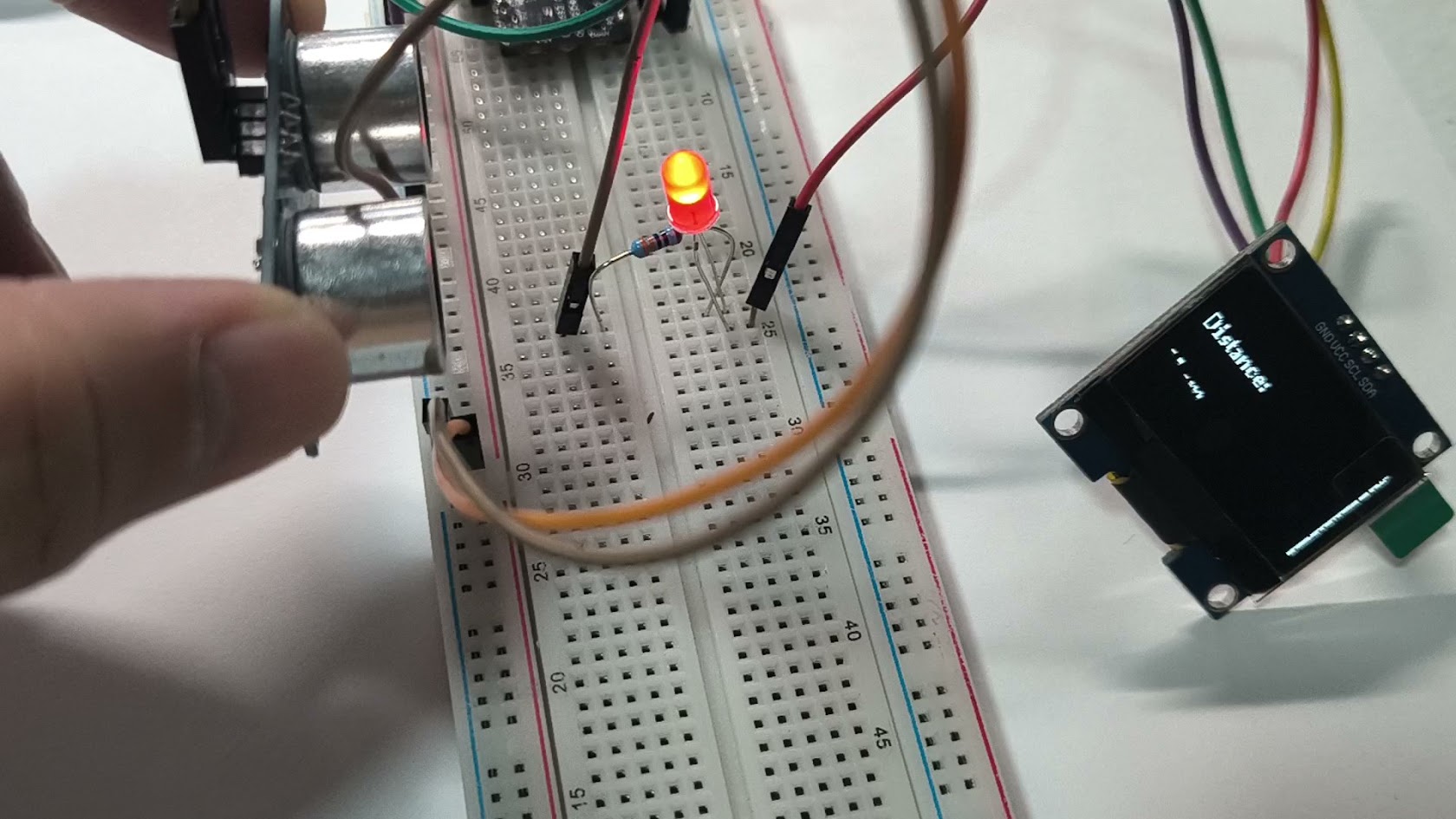
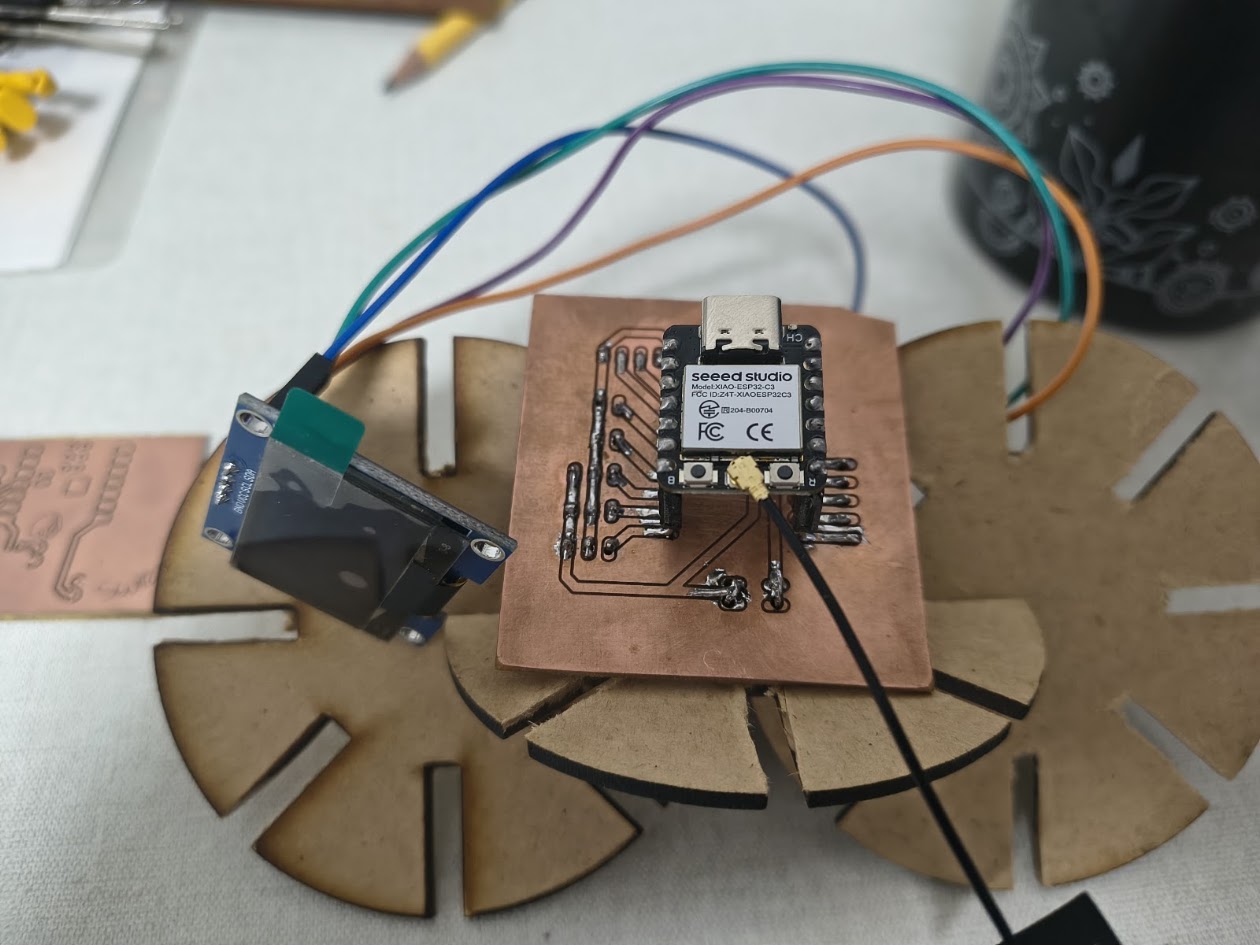
We repeated the demonstration in Week 9. Input/Output devices were connected.
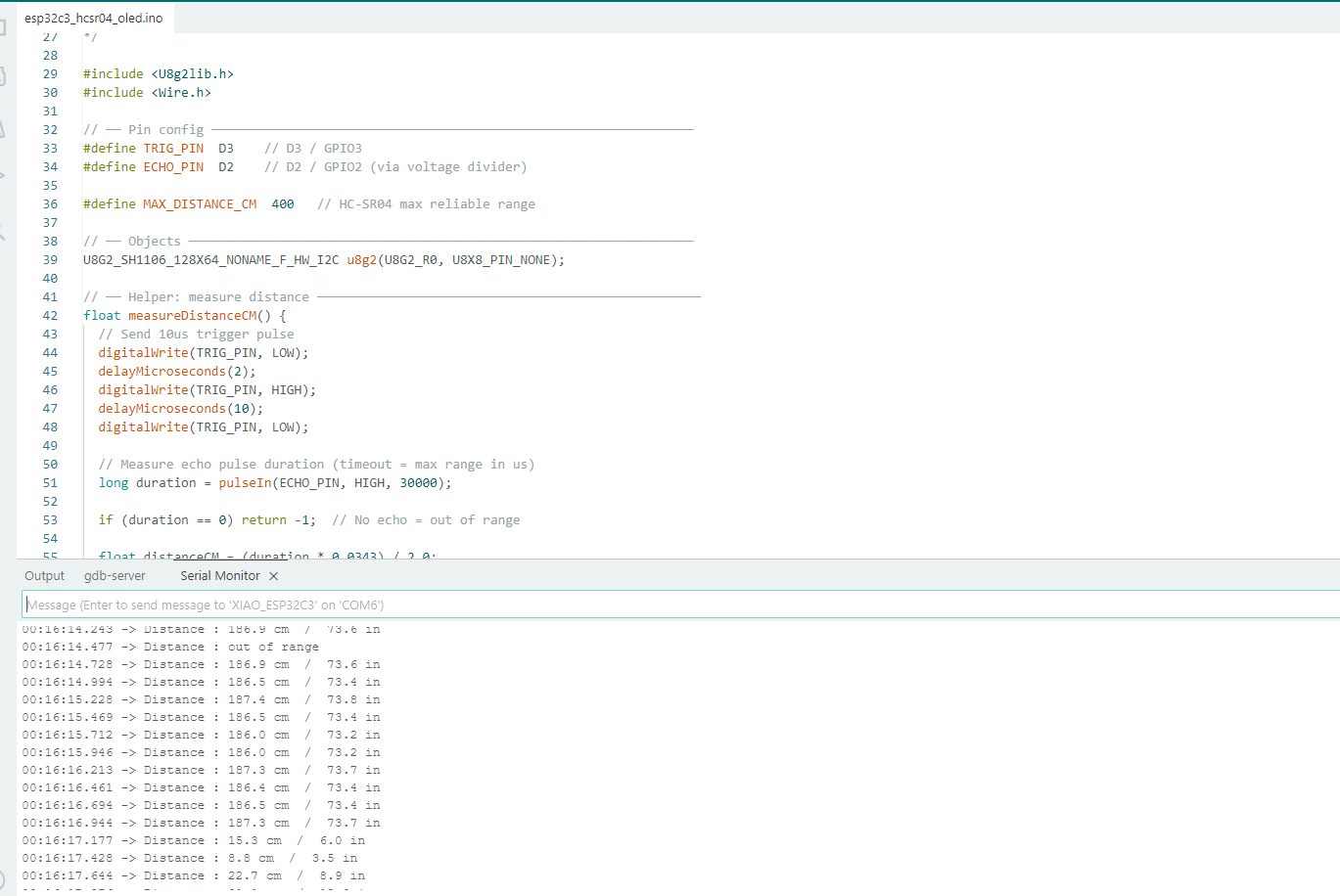
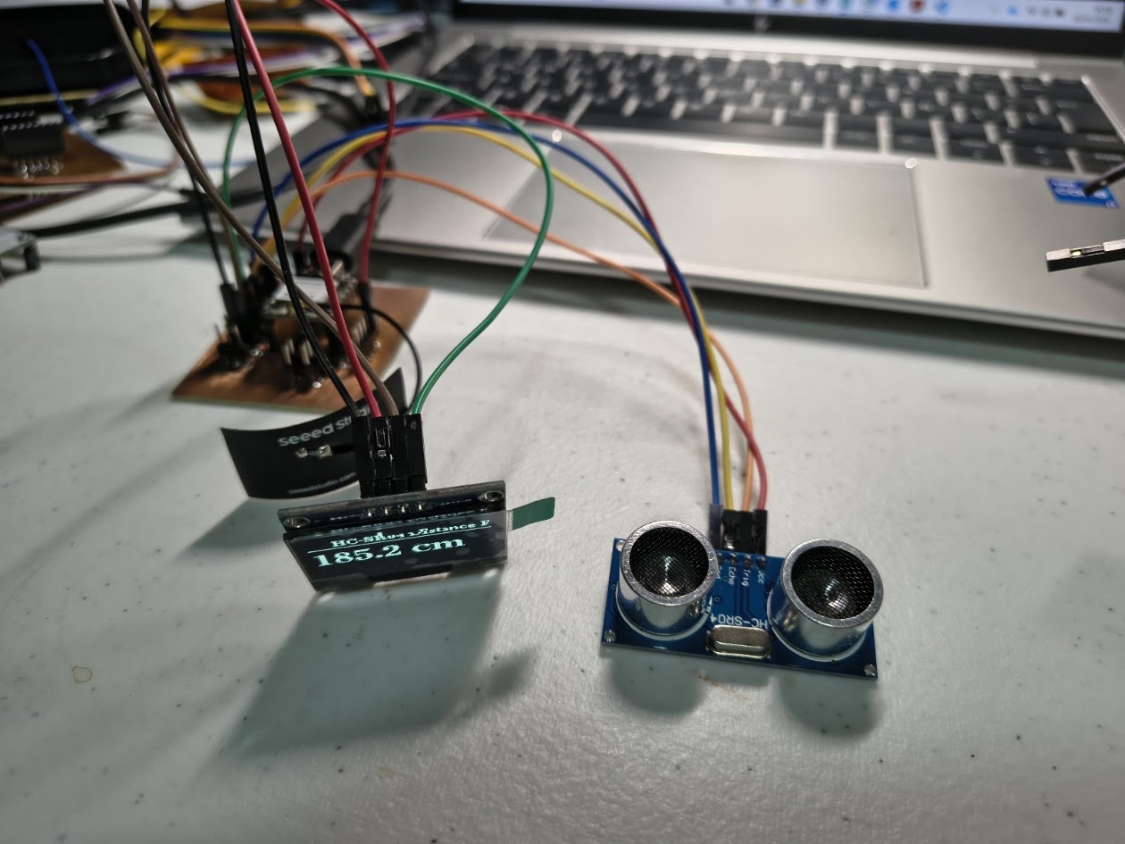
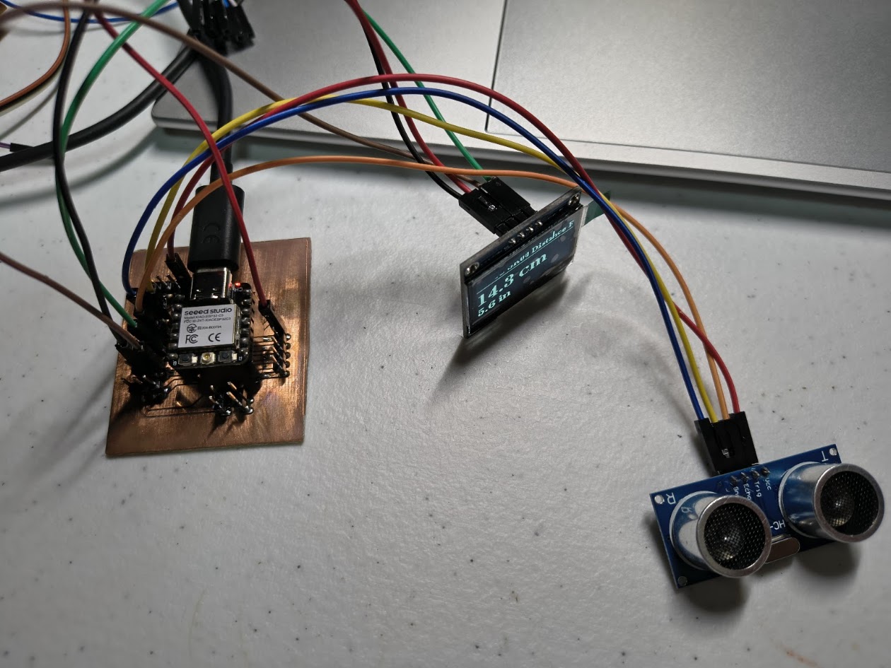
ESP32-C3 (Xiao) + HC-SR04 Ultrasonic + 1.3" OLED I2C
-------------------------------------------------------
Board : Seeed Studio XIAO ESP32-C3
Sensor : HC-SR04 Ultrasonic Distance Sensor
Display : 1.3" OLED SH1106 I2C
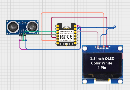
HC-SR04 Wiring:
HC-SR04 VCC → 5V
HC-SR04 GND → GND
HC-SR04 TRIG → D3 (GPIO3)
HC-SR04 ECHO → D2 (GPIO2) via voltage divider (see below!)
!! HC-SR04 ECHO outputs 5V — ESP32-C3 is NOT 5V tolerant !!
!! Use a voltage divider on ECHO pin: !!
!! ECHO → 1kΩ → D2 (GPIO2) !!
!! └── 2kΩ → GND !!
OLED I2C Wiring:
OLED VCC → 3.3V
OLED GND → GND
OLED SDA → D4 (GPIO4)
OLED SCL → D5 (GPIO5)
Libraries needed:
- U8g2 by oliver
*/
#include
#include
// ── Pin config ────────────────────────────────────────────────────────────────
#define TRIG_PIN D3 // D3 / GPIO3
#define ECHO_PIN D2 // D2 / GPIO2 (via voltage divider)
#define MAX_DISTANCE_CM 400 // HC-SR04 max reliable range
// ── Objects ───────────────────────────────────────────────────────────────────
U8G2_SH1106_128X64_NONAME_F_HW_I2C u8g2(U8G2_R0, U8X8_PIN_NONE);
// ── Helper: measure distance ───────────────────────────────────────────────────
float measureDistanceCM() {
// Send 10us trigger pulse
digitalWrite(TRIG_PIN, LOW);
delayMicroseconds(2);
digitalWrite(TRIG_PIN, HIGH);
delayMicroseconds(10);
digitalWrite(TRIG_PIN, LOW);
// Measure echo pulse duration (timeout = max range in us)
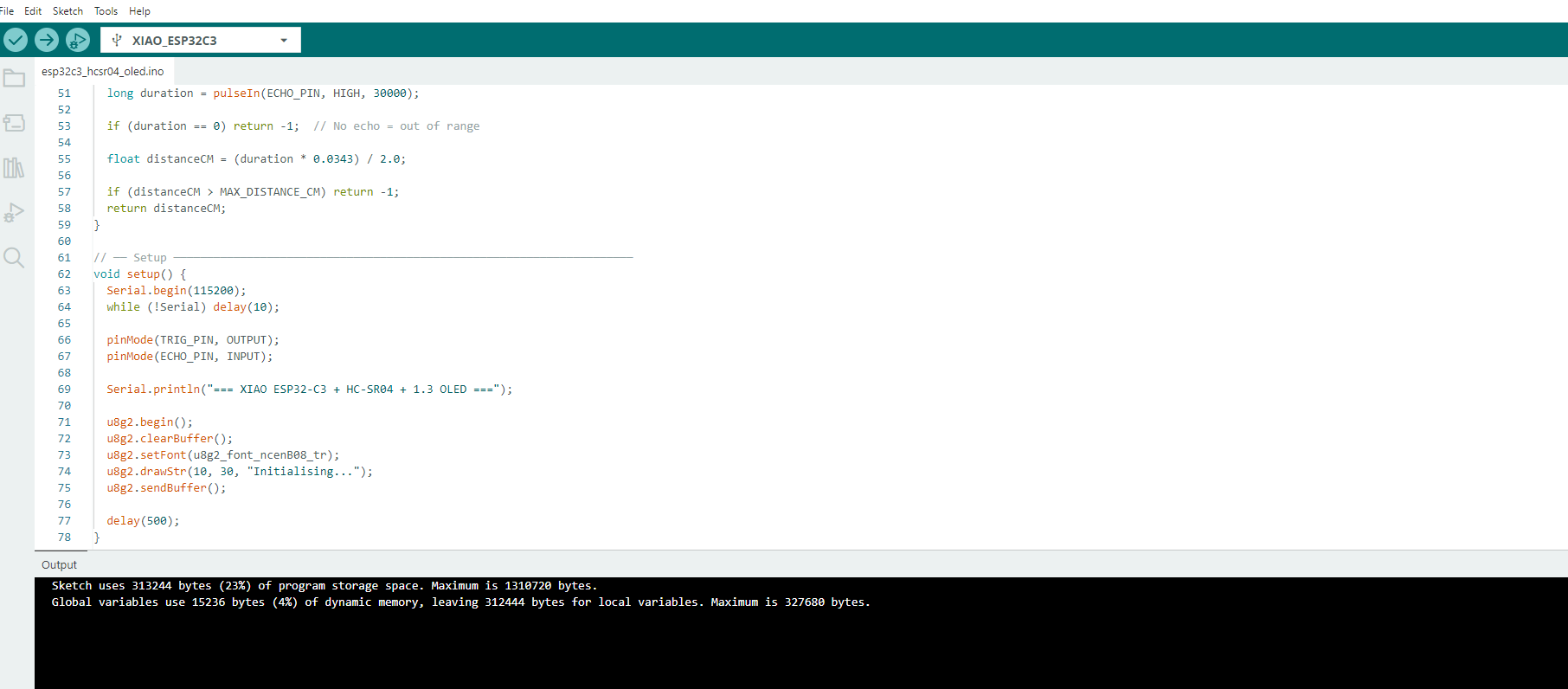
long duration = pulseIn(ECHO_PIN, HIGH, 30000);
if (duration == 0) return -1; // No echo = out of range
float distanceCM = (duration * 0.0343) / 2.0;
if (distanceCM > MAX_DISTANCE_CM) return -1;
return distanceCM;
}
// ── Setup ─────────────────────────────────────────────────────────────────────
void setup() {
Serial.begin(115200);
while (!Serial) delay(10);
pinMode(TRIG_PIN, OUTPUT);
pinMode(ECHO_PIN, INPUT);
Serial.println("=== XIAO ESP32-C3 + HC-SR04 + 1.3 OLED ===");
u8g2.begin();
u8g2.clearBuffer();
u8g2.setFont(u8g2_font_ncenB08_tr);
u8g2.drawStr(10, 30, "Initialising...");
u8g2.sendBuffer();
delay(500);
}
// ── Main Loop ─────────────────────────────────────────────────────────────────
void loop() {
float distCM = measureDistanceCM();
float distIN = distCM / 2.54;
// ── Serial output ──
if (distCM < 0) {
Serial.println("Distance : out of range");
} else {
Serial.print("Distance : ");
Serial.print(distCM, 1);
Serial.print(" cm / ");
Serial.print(distIN, 1);
Serial.println(" in");
}
// ── OLED display ──
u8g2.clearBuffer();
// Title
u8g2.setFont(u8g2_font_ncenB08_tr);
u8g2.drawStr(18, 12, "HC-SR04 Distance Fab");
u8g2.drawHLine(0, 15, 128);
if (distCM < 0) {
u8g2.setFont(u8g2_font_ncenB12_tr);
u8g2.drawStr(10, 42, "Out of range");
} else {
char lineCM[20], lineIN[20];
snprintf(lineCM, sizeof(lineCM), "%.1f cm", distCM);
snprintf(lineIN, sizeof(lineIN), "%.1f in", distIN);
u8g2.setFont(u8g2_font_ncenB18_tr); // big font for cm
u8g2.drawStr(0, 42, lineCM);
u8g2.setFont(u8g2_font_ncenB12_tr); // smaller for inches
u8g2.drawStr(0, 62, lineIN);
}
u8g2.sendBuffer();
delay(200); // update 5x per second for smooth readings
}
Video demonstration
4) Final project advance
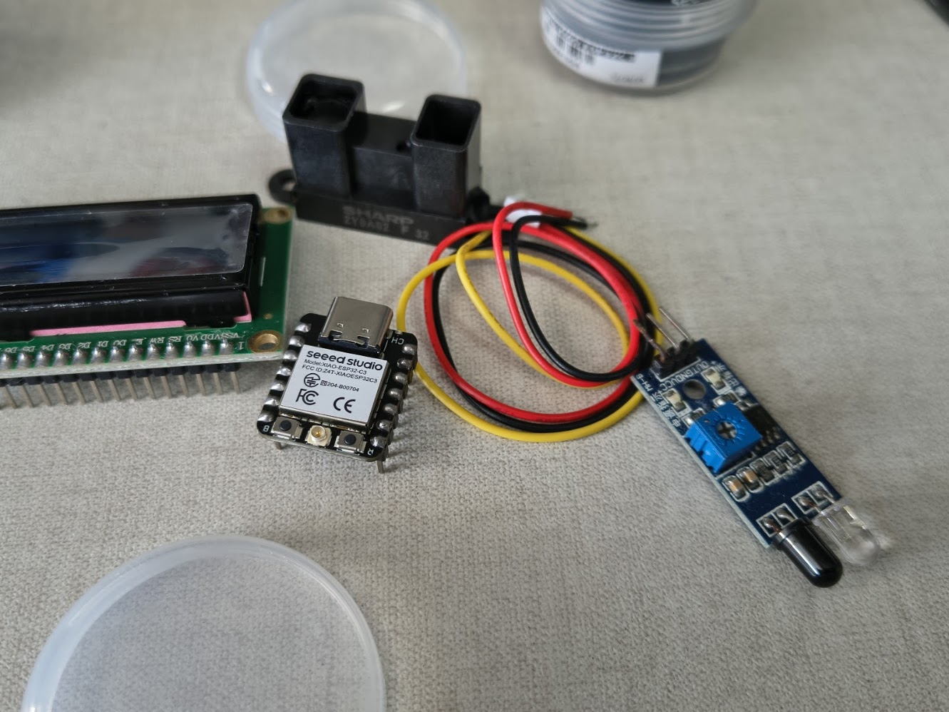
Devices
GP2Y0A21YK0F Sharp, infrared distance sensor, 10-80 cm
GP2Y0A02YK0F Sharp, infrared distance sensor, 20-150 cm
2Y0A710K Sharp, infrared distance sensor, 100 a 550cm
5) Final results
- Linked to the group assignment page
- Documented how you determined power consumption of an output device with your group
- Documented what you learned from interfacing output device(s) to microcontroller and controlling
- Linked to the board you made in a previous assigment or documented your design and fabrication
- Explain how your code works
- Explained any problems you encountered and how you fixed them
- Include original source code and any design files
- Included a 'hero shot' of your board
6) References files
We learn how to design, make and test a PCB with sensor. Files: in each section