Assignment requirements
Group assignment
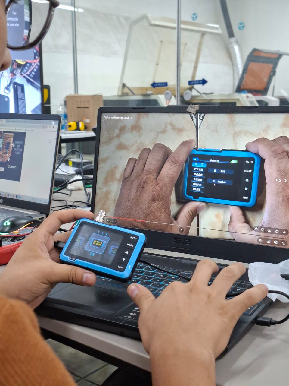
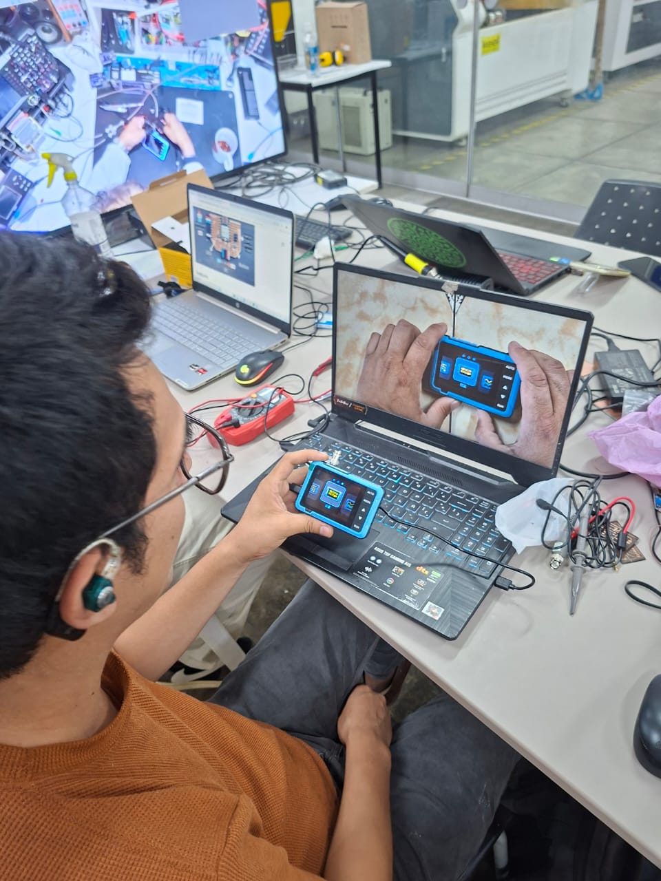
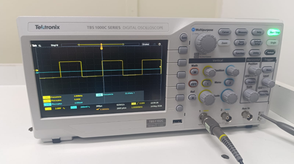
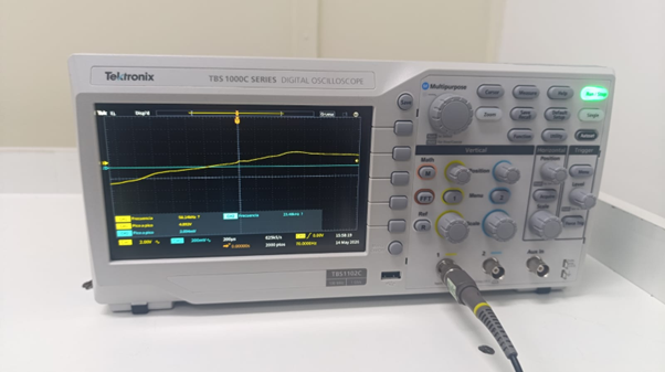
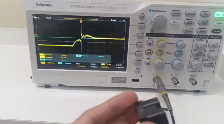
- Test an input device(s)'s analog levels and digital signals (As a minimum, you should demonstrate the use of a multimeter and an oscilloscope
- Document your work on the group work page and reflect on your individual page what you learned
Individual assignment
- Measure something: add a sensor to a microcontroller board that you have designed and read it
Progress status
Test an input device analog levels and digital signals
Add a sensor to a microcontroller board that you have designed and read it
Upload source files.
1) Introduction
Closing gaps
- Learn about input devices
- Interact more with Arduino IDE
- Discuss the group project
- Develop the individual project
2) Group assignment 1 - Test an input devices (analog & digital)
For more details visit Fab Lab Peru Week 9 Group assignment
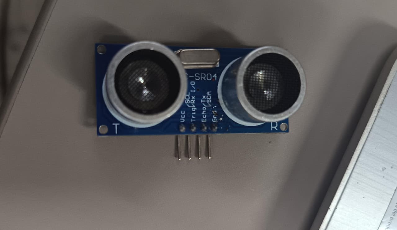
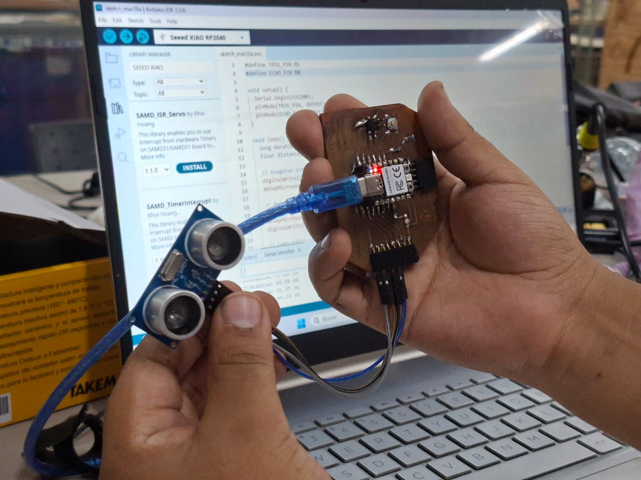
Project idea
- Ultrasonic HC-SR04 sensor module
- Measures distance using sound waves
- Includes transmitter and receiver
- Range: 2 cm to 500 cm
- Pins: Vcc, Trig, Echo, GND

Video demonstration
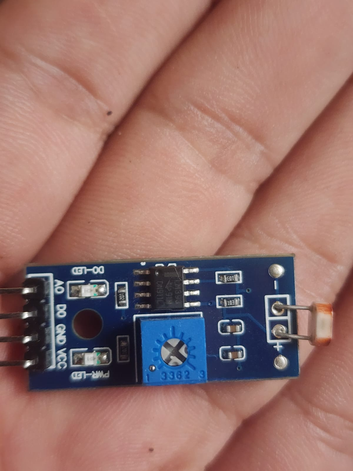
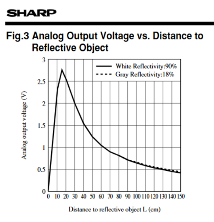
3) Group assignment 2 - Test an input devices (analog & digital)
More information at Fab Lab Peru - Group Assignment: https://fabacademy.org/2026/labs/lima/#page-top
Project idea
- Distance detection
- Driving ability - 15mA with adjustable potentiometer
- Brightness - Adjustable
- Detect - brightness and light intensity
- Analog and digital output
Video demonstration
4) Individual assigment
Problems
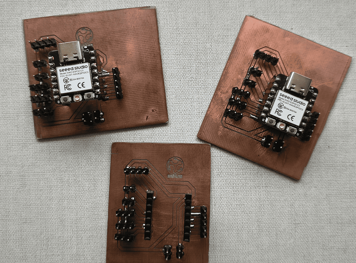
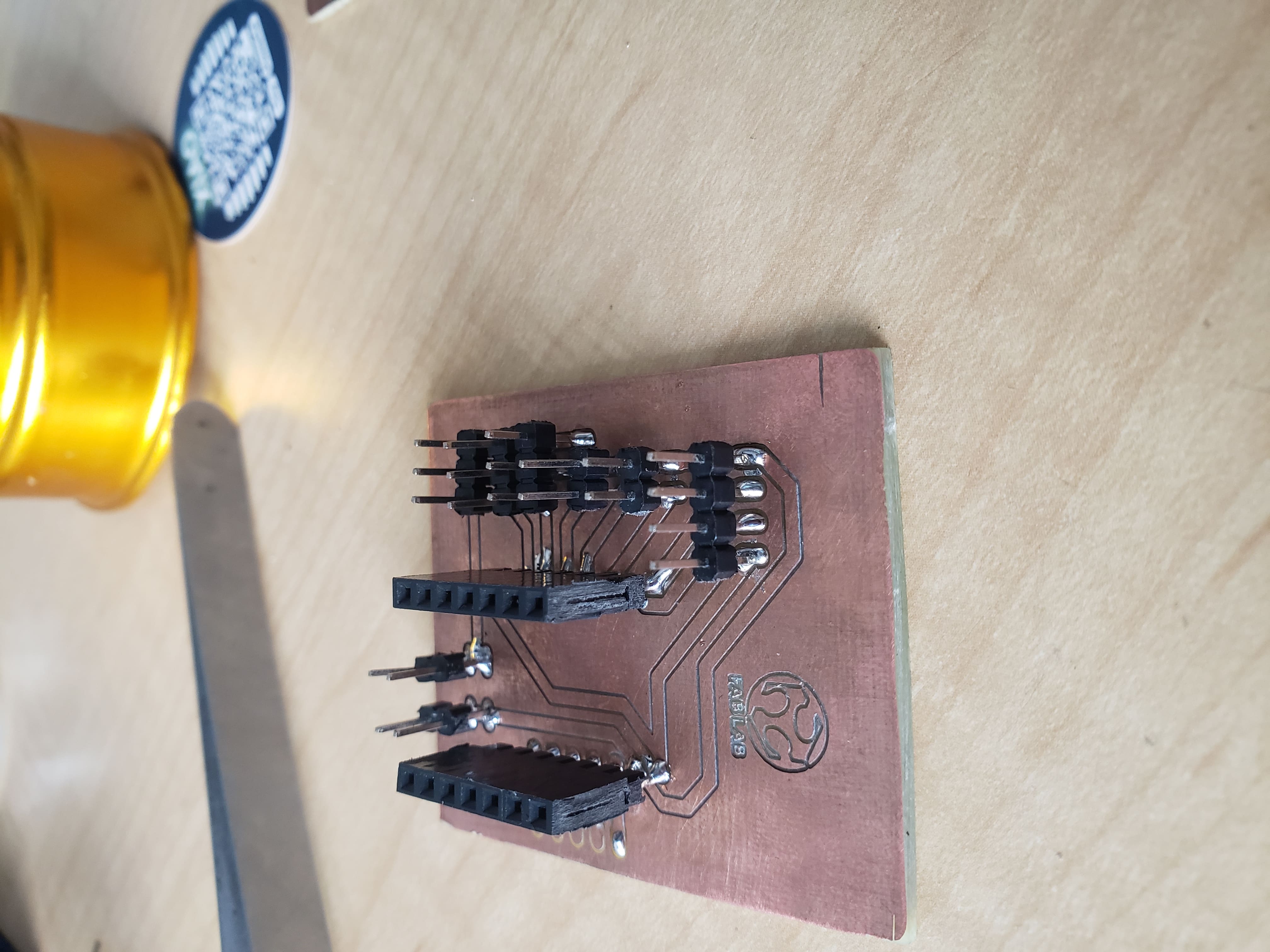
Designed microcontroller board doesn't work
Posible solution - make a new board
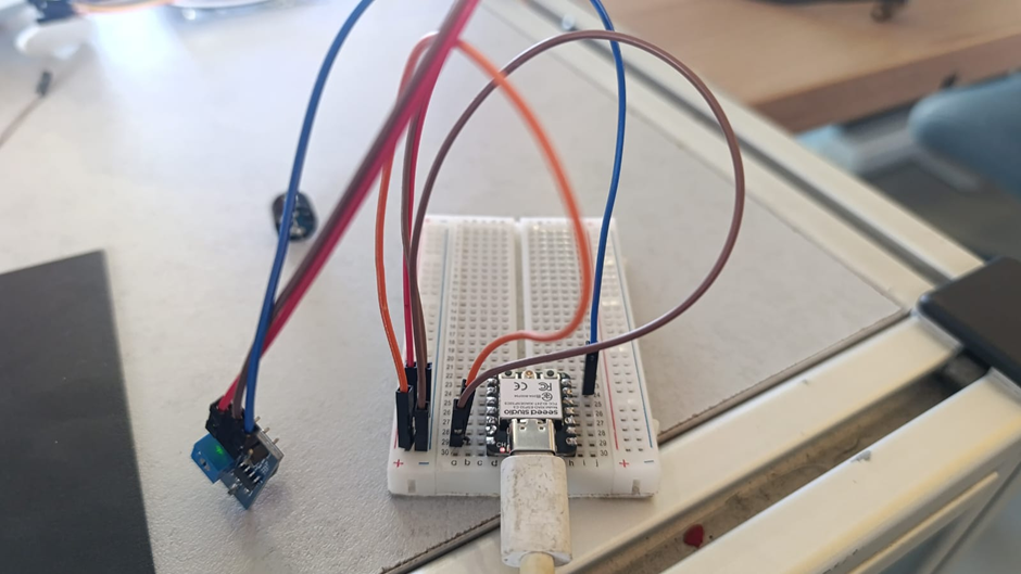
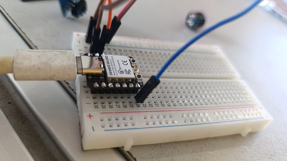
Step 1 - Protoboard
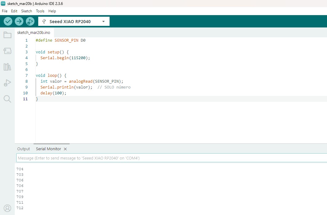
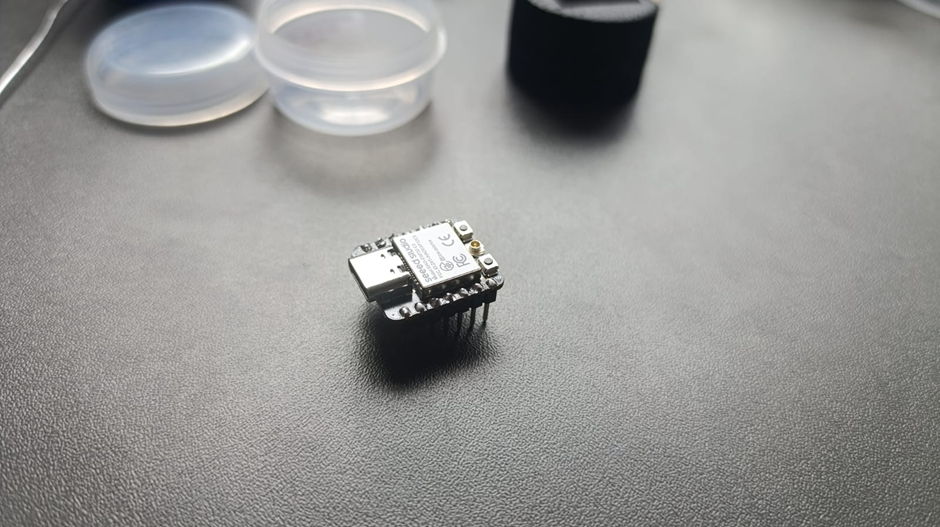
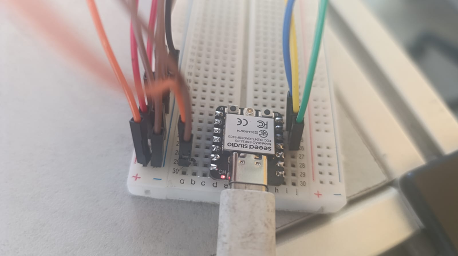
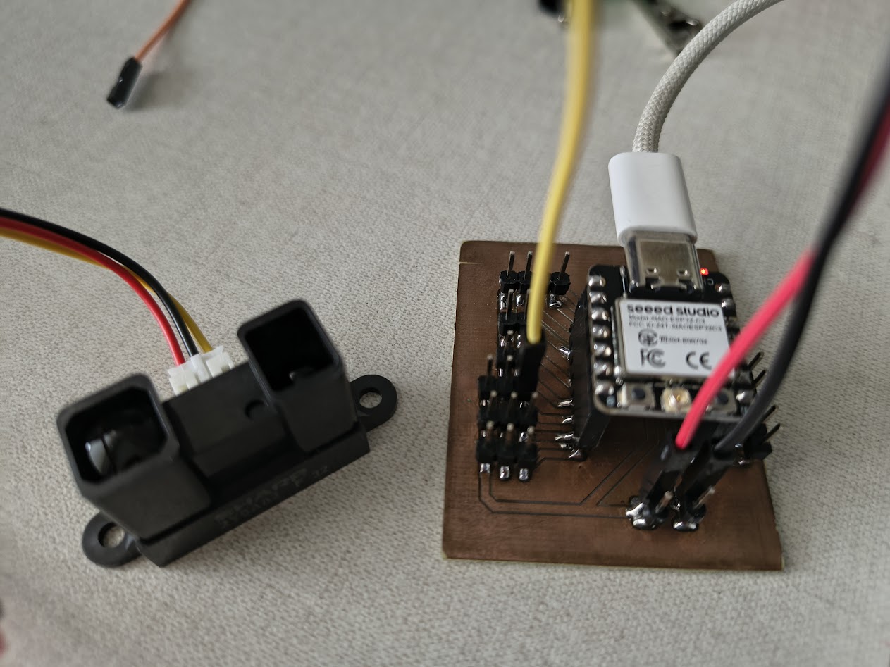
Mesasure something with the microcontroller Xiao ESP32 C3
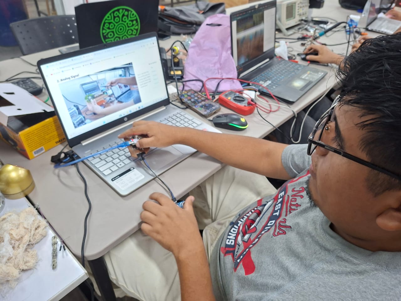
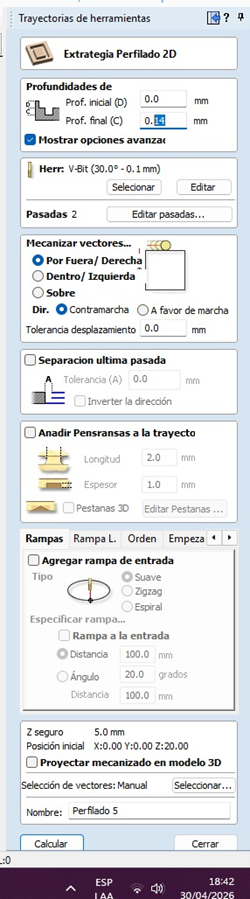
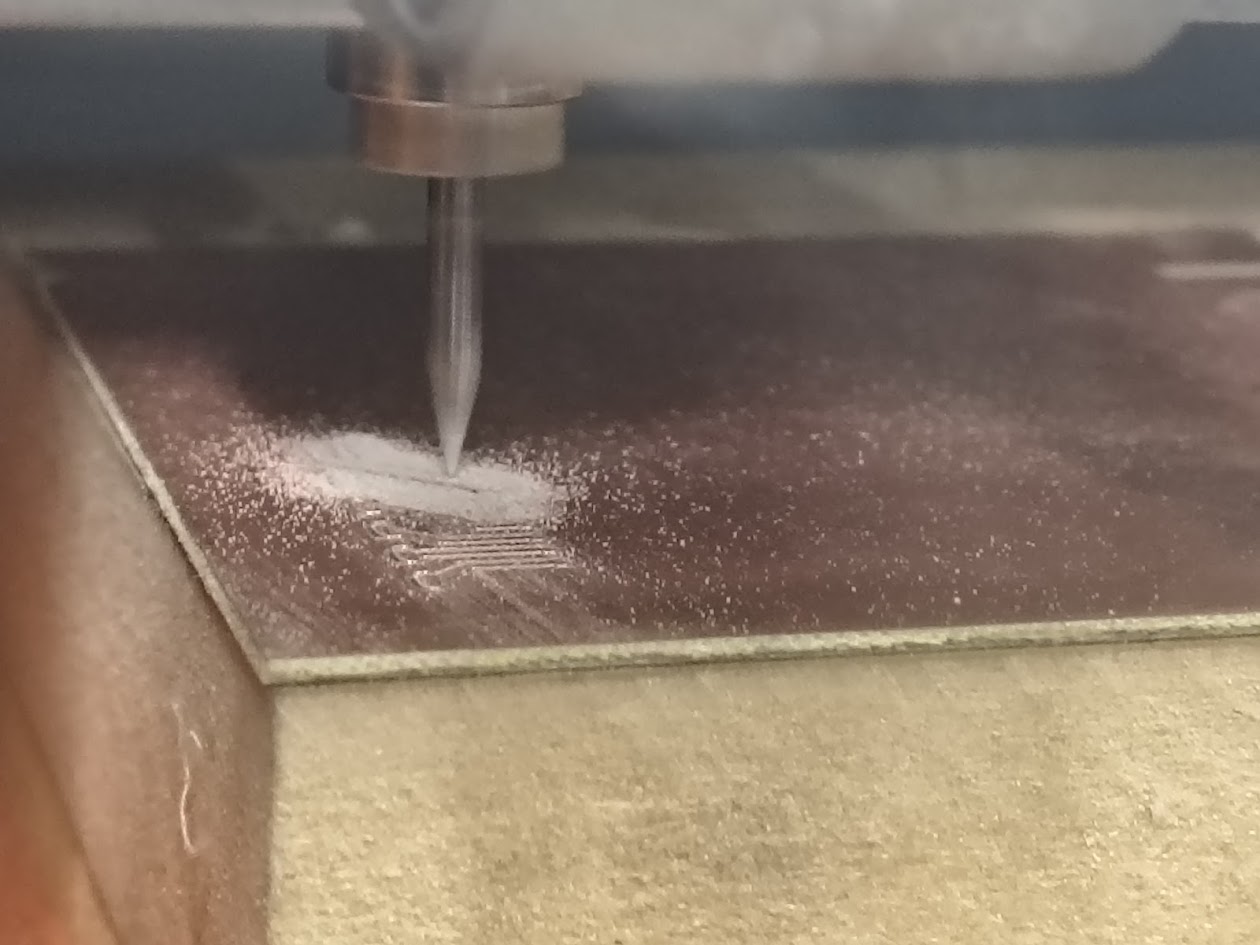
Step 2 - Repeat with a new board
Measure and test devices using a multimeter or an oscilloscope
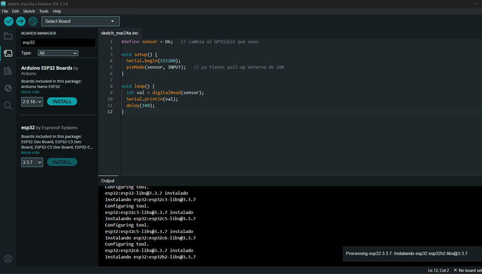
// TCRT5000L reflective optical sensor
// Input devices
// Board: Seeed Studio XIAO ECP 32 C3
#define sensor = D6; // cambia al GPIO/pin que uses
void setup() {
Serial.begin(115200);
pinMode(sensor, INPUT);
}
void loop() {
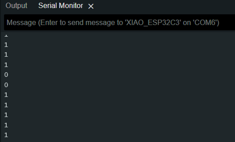
int val = digitalRead(sensor);
Serial.println(val);
delay(100);
}
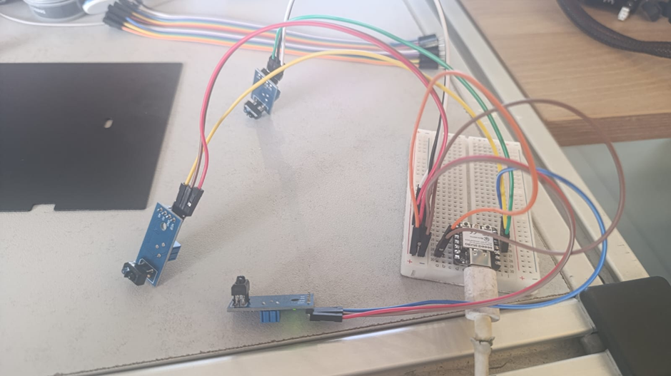
// Using three TCRT5000L reflective optical sensor
// Input devices
// Board: Seeed Studio XIAO ESP 32 C3
#define sensor1 D6 // cambia al GPIO/pin que uses
#define sensor2 D5 // cambia al GPIO/pin que uses
#define sensor3 D4 // cambia al GPIO/pin que uses
void setup() {
Serial.begin(115200);
pinMode(sensor1, INPUT);
pinMode(sensor2, INPUT);
pinMode(sensor3, INPUT);
}
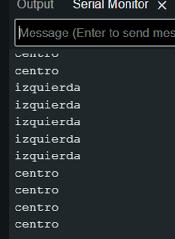
void loop() {
int val1 = digitalRead(sensor1);
int val2 = digitalRead(sensor2);
int val3 = digitalRead(sensor3);
if(val1==1){
Serial.println("izquierda");
}
else if(val2==1){
Serial.println("centro");
}
else if(val3==1){
Serial.println("derecha");
}
else{
Serial.println("error");
}
delay(100);
}
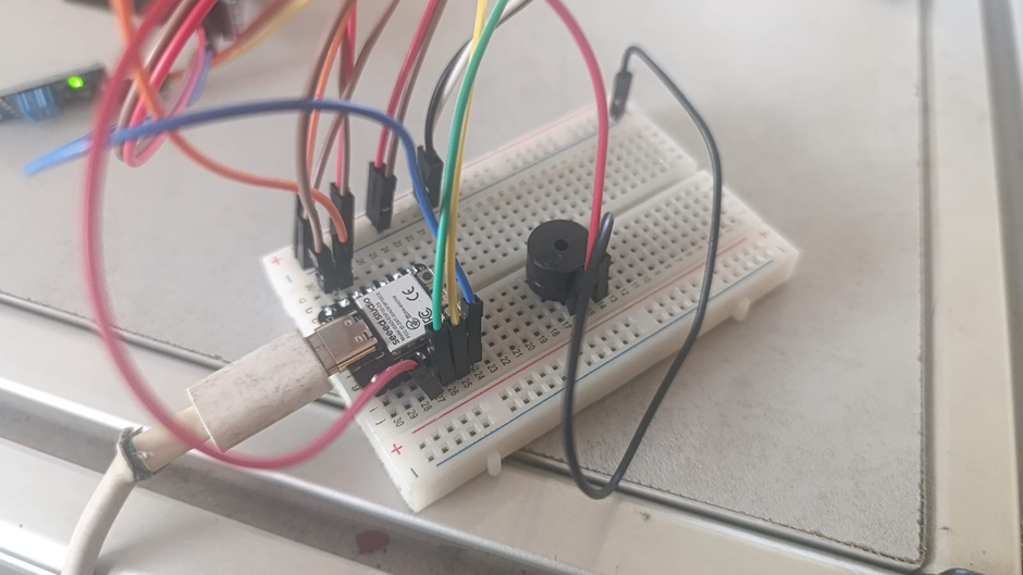
// Using three TCRT5000L reflective optical sensor & buzzer - Center or not
              // Input devices
              // Board: Seeed Studio XIAO ESP 32 C3

              #define sensor1 D6   // cambia al GPIO/pin que uses
              #define sensor2 D5   // cambia al GPIO/pin que uses
              #define sensor3 D4   // cambia al GPIO/pin que uses


              void setup() {
                  Serial.begin(115200);
                  pinMode(sensor1, INPUT);
                  pinMode(sensor2, INPUT);
                  pinMode(sensor3, INPUT);
                  pinMode(D3, OUTPUT);
              }

              void loop() {
                int val1 = digitalRead(sensor1);
                int val2 = digitalRead(sensor2);
                int val3 = digitalRead(sensor3);
                if(val1==1){
                  Serial.println("izquierda");
                    digitalWrite (D3, HIGH);
                    delayMicroseconds (5000);
                    digitalWrite (D3, LOW);
                    delayMicroseconds (100000);
                }
                else if(val2==1){
                  Serial.println("centro");
                }
                else if(val3==1){
                  Serial.println("derecha");
                    digitalWrite (D3, HIGH);
                    delayMicroseconds (5000);
                    digitalWrite (D3, LOW);
                    delayMicroseconds (100000);
                }
                else{
                  Serial.println("error");
                    digitalWrite (D3, HIGH);
                    delayMicroseconds (5000);
                    digitalWrite (D3, LOW);
                    delayMicroseconds (100000);
                }
                delay(100);
              }
4.1) Additional individual assigment
Details
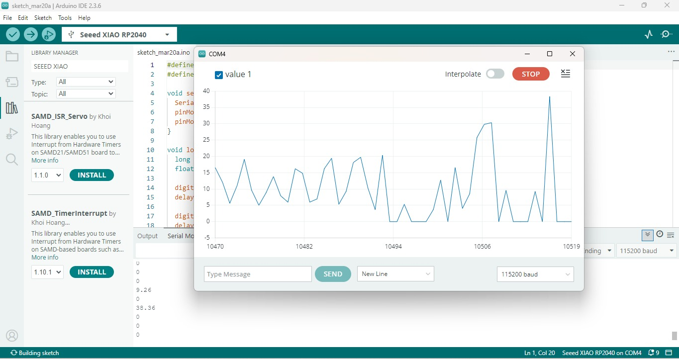
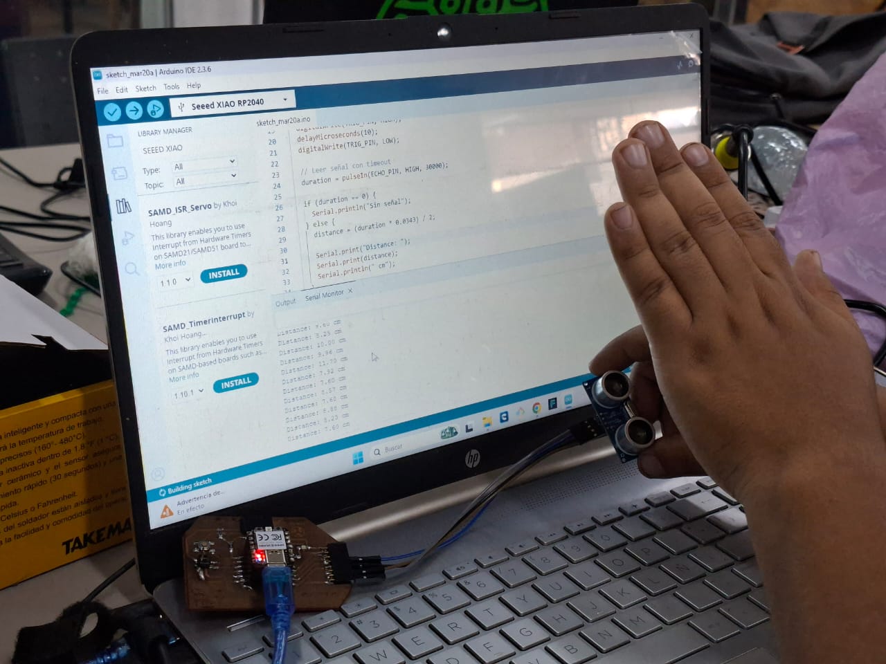
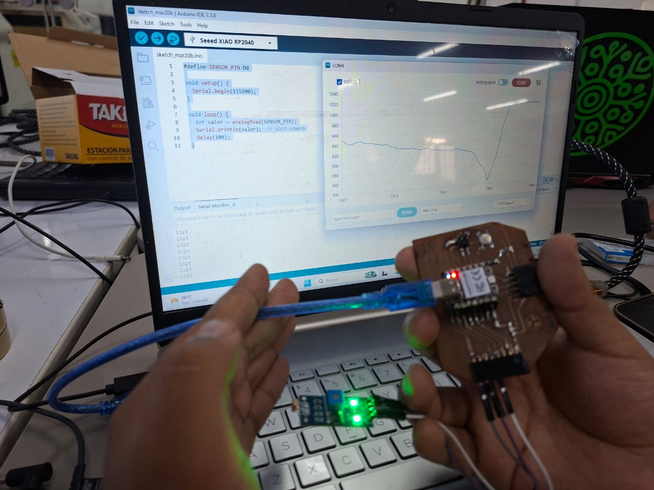
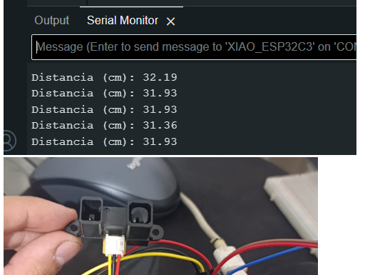
Designed microcontroller board read real
Showed output - serial monitor valuess
Included code
Demostrate that its works
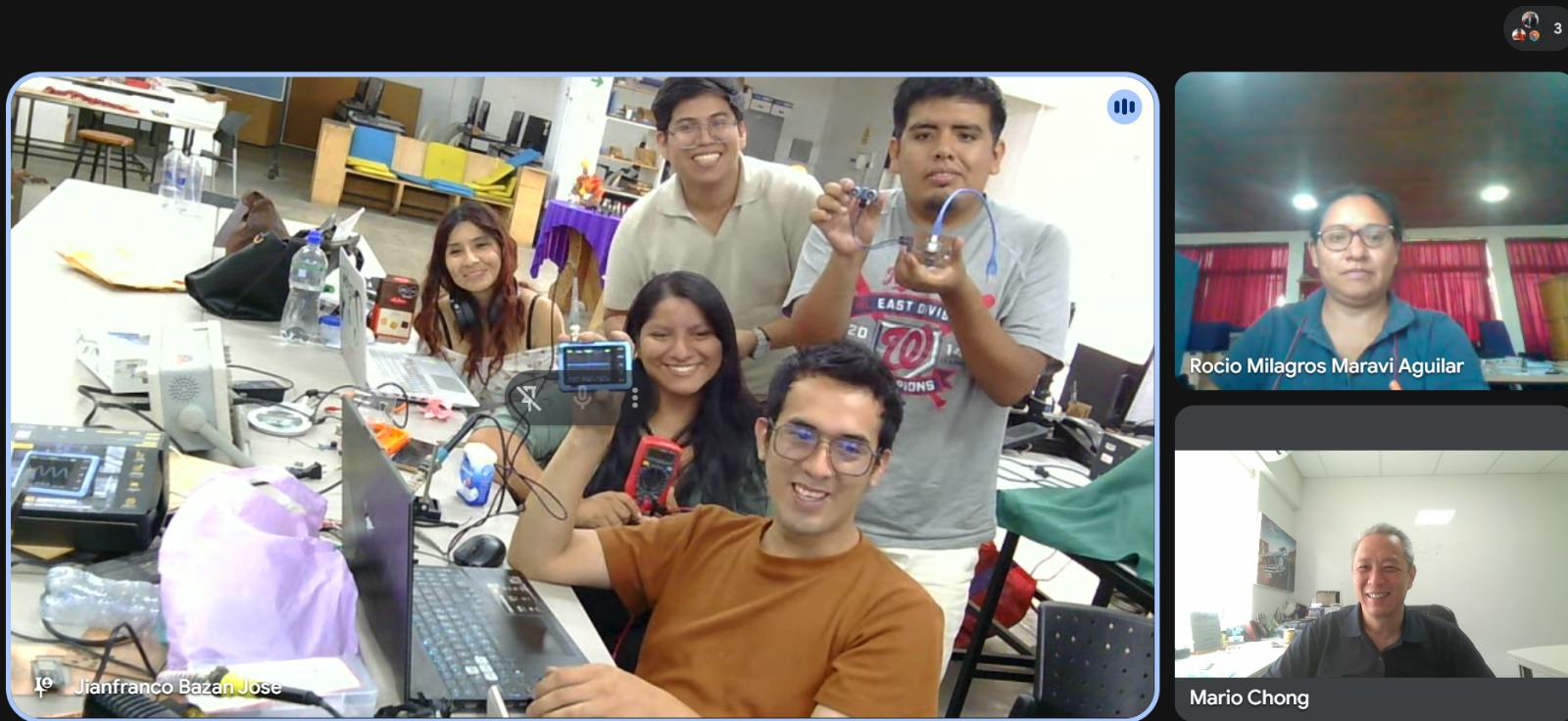
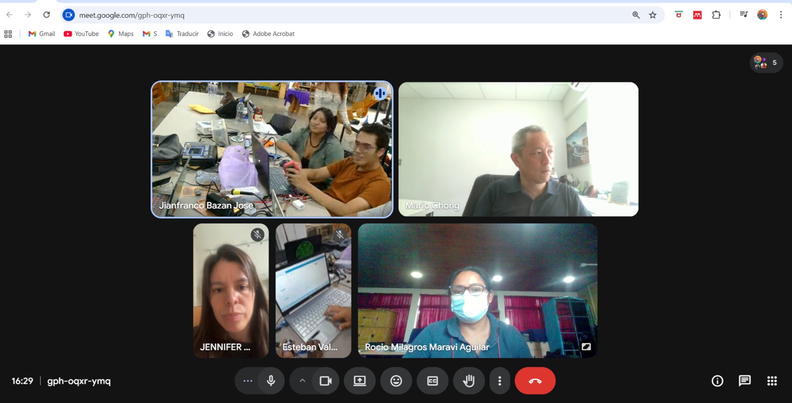
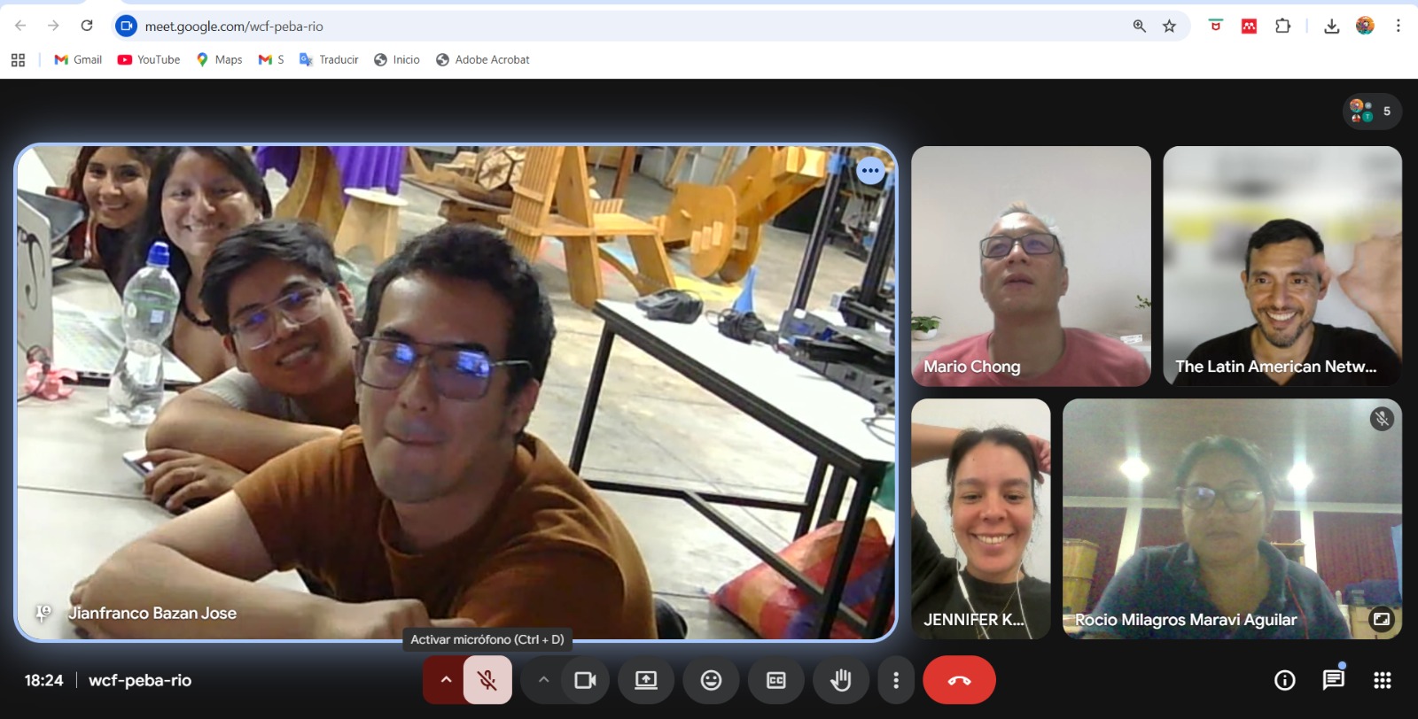
We repeated the demonstration in Week 10. Input/Output devices were connected.
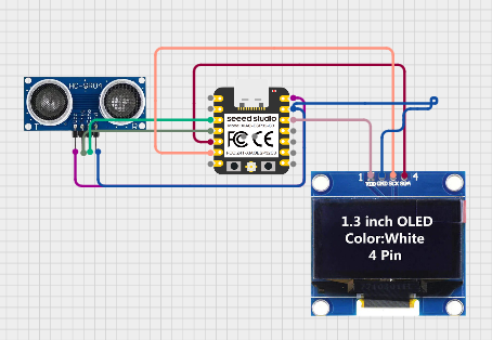
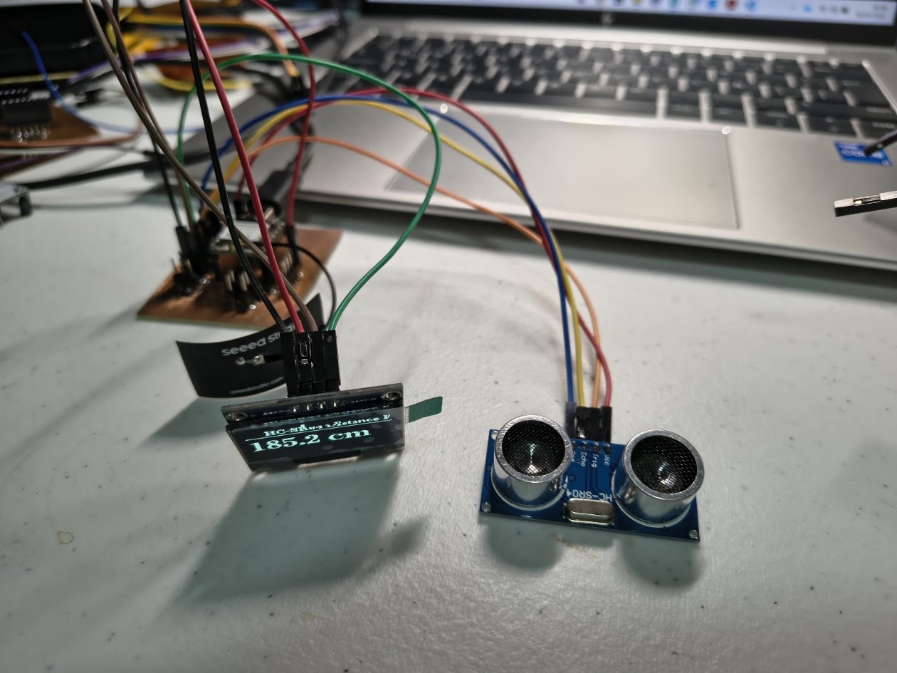
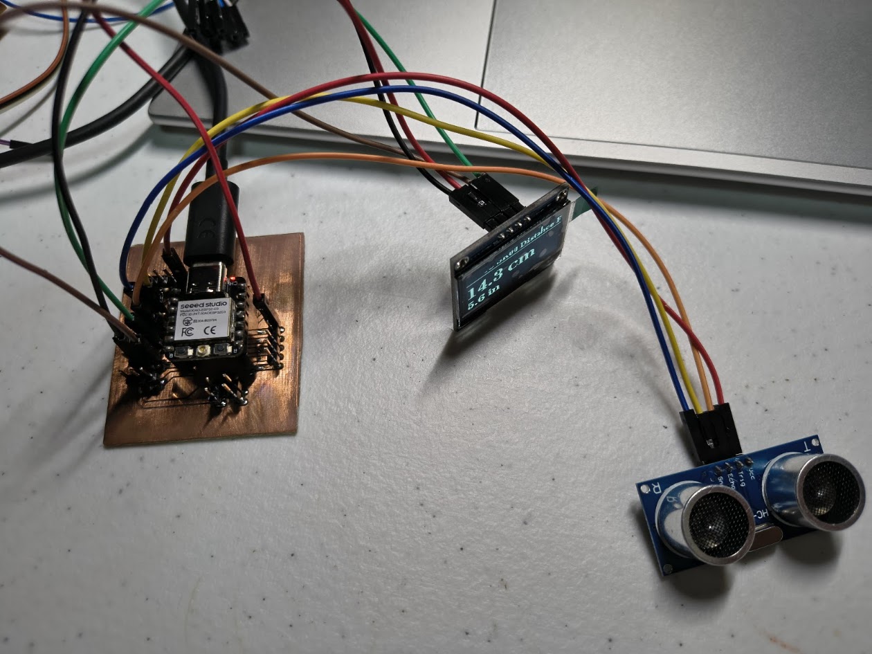
ESP32-C3 (Xiao) + HC-SR04 Ultrasonic + 1.3" OLED I2C
-------------------------------------------------------
Board : Seeed Studio XIAO ESP32-C3
Sensor : HC-SR04 Ultrasonic Distance Sensor
Display : 1.3" OLED SH1106 I2C
HC-SR04 Wiring:
HC-SR04 VCC → 5V
HC-SR04 GND → GND
HC-SR04 TRIG → D3 (GPIO3)
HC-SR04 ECHO → D2 (GPIO2) via voltage divider (see below!)
!! HC-SR04 ECHO outputs 5V — ESP32-C3 is NOT 5V tolerant !!
!! Use a voltage divider on ECHO pin: !!
!! ECHO → 1kΩ → D2 (GPIO2) !!
!! └── 2kΩ → GND !!
OLED I2C Wiring:
OLED VCC → 3.3V
OLED GND → GND
OLED SDA → D4 (GPIO4)
OLED SCL → D5 (GPIO5)
Libraries needed:
- U8g2 by oliver
*/
#include
#include
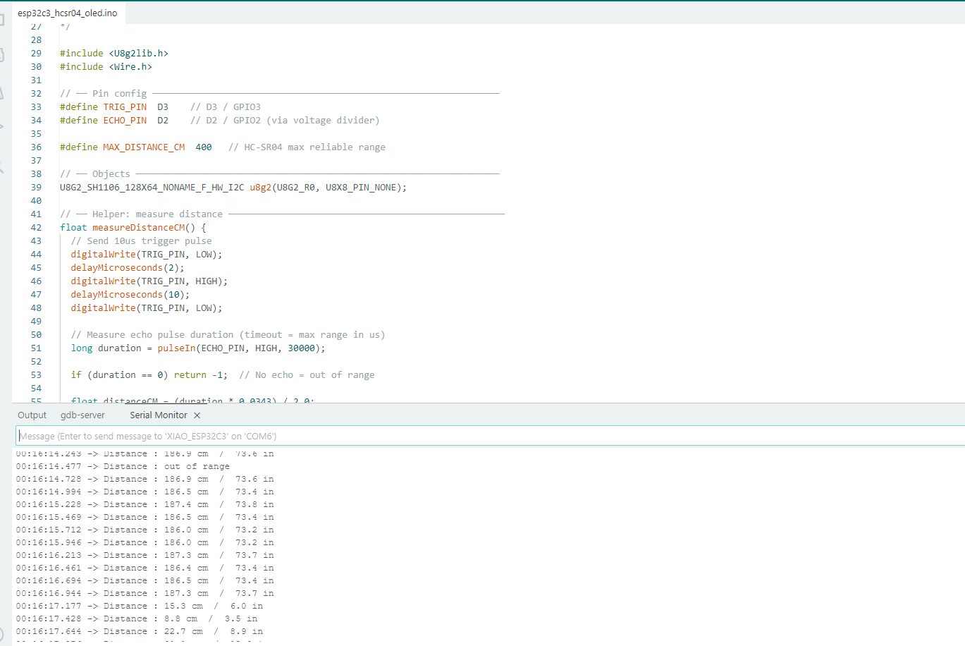
// ── Pin config ────────────────────────────────────────────────────────────────
#define TRIG_PIN D3 // D3 / GPIO3
#define ECHO_PIN D2 // D2 / GPIO2 (via voltage divider)
#define MAX_DISTANCE_CM 400 // HC-SR04 max reliable range
// ── Objects ───────────────────────────────────────────────────────────────────
U8G2_SH1106_128X64_NONAME_F_HW_I2C u8g2(U8G2_R0, U8X8_PIN_NONE);
// ── Helper: measure distance ───────────────────────────────────────────────────
float measureDistanceCM() {
// Send 10us trigger pulse
digitalWrite(TRIG_PIN, LOW);
delayMicroseconds(2);
digitalWrite(TRIG_PIN, HIGH);
delayMicroseconds(10);
digitalWrite(TRIG_PIN, LOW);
// Measure echo pulse duration (timeout = max range in us)
long duration = pulseIn(ECHO_PIN, HIGH, 30000);
if (duration == 0) return -1; // No echo = out of range
float distanceCM = (duration * 0.0343) / 2.0;
if (distanceCM > MAX_DISTANCE_CM) return -1;
return distanceCM;
}
// ── Setup ─────────────────────────────────────────────────────────────────────
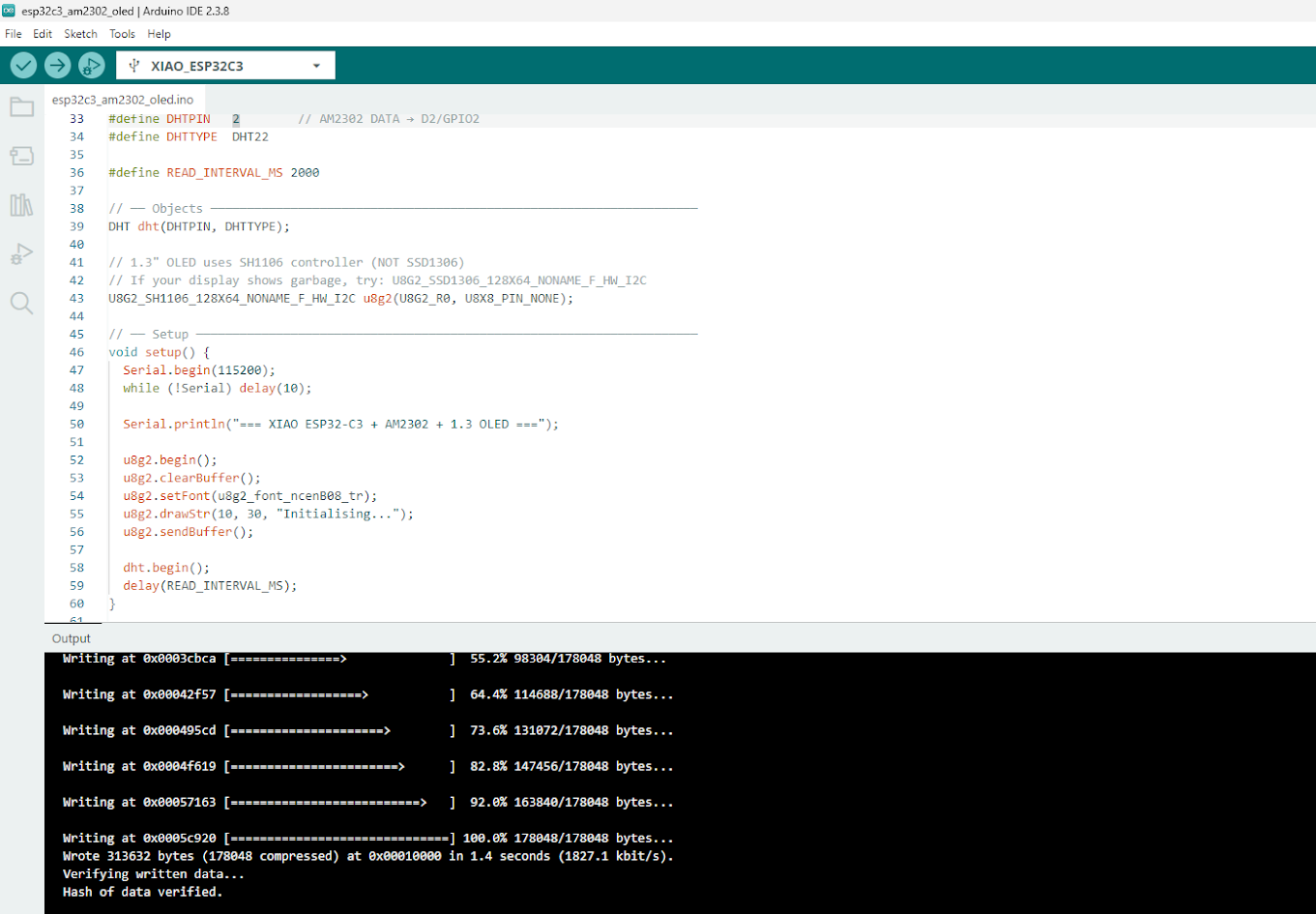
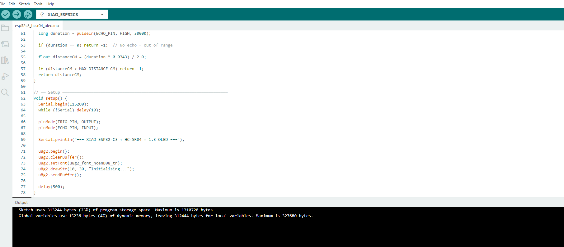
void setup() {
Serial.begin(115200);
while (!Serial) delay(10);
pinMode(TRIG_PIN, OUTPUT);
pinMode(ECHO_PIN, INPUT);
Serial.println("=== XIAO ESP32-C3 + HC-SR04 + 1.3 OLED ===");
u8g2.begin();
u8g2.clearBuffer();
u8g2.setFont(u8g2_font_ncenB08_tr);
u8g2.drawStr(10, 30, "Initialising...");
u8g2.sendBuffer();
delay(500);
}
// ── Main Loop ─────────────────────────────────────────────────────────────────
void loop() {
float distCM = measureDistanceCM();
float distIN = distCM / 2.54;
// ── Serial output ──
if (distCM < 0) {
Serial.println("Distance : out of range");
} else {
Serial.print("Distance : ");
Serial.print(distCM, 1);
Serial.print(" cm / ");
Serial.print(distIN, 1);
Serial.println(" in");
}
// ── OLED display ──
u8g2.clearBuffer();
// Title
u8g2.setFont(u8g2_font_ncenB08_tr);
u8g2.drawStr(18, 12, "HC-SR04 Distance Fab");
u8g2.drawHLine(0, 15, 128);
if (distCM < 0) {
u8g2.setFont(u8g2_font_ncenB12_tr);
u8g2.drawStr(10, 42, "Out of range");
} else {
char lineCM[20], lineIN[20];
snprintf(lineCM, sizeof(lineCM), "%.1f cm", distCM);
snprintf(lineIN, sizeof(lineIN), "%.1f in", distIN);
u8g2.setFont(u8g2_font_ncenB18_tr); // big font for cm
u8g2.drawStr(0, 42, lineCM);
u8g2.setFont(u8g2_font_ncenB12_tr); // smaller for inches
u8g2.drawStr(0, 62, lineIN);
}
u8g2.sendBuffer();
delay(200); // update 5x per second for smooth readings
}
Video demonstration
4.2) Additional individual assignment 2
Details
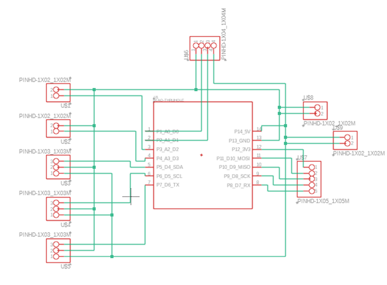
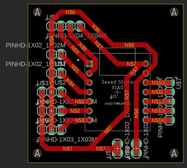
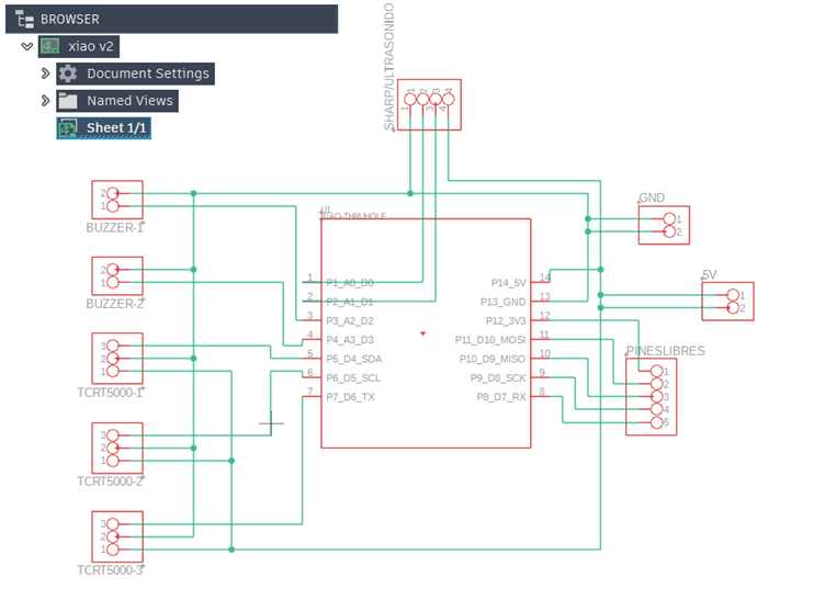
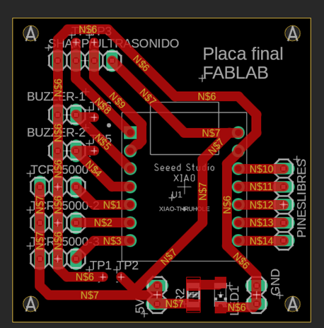
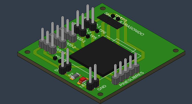
Use your own PCB, show: schematic, working with sensor
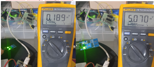
Add mesasure reading - voltaje value
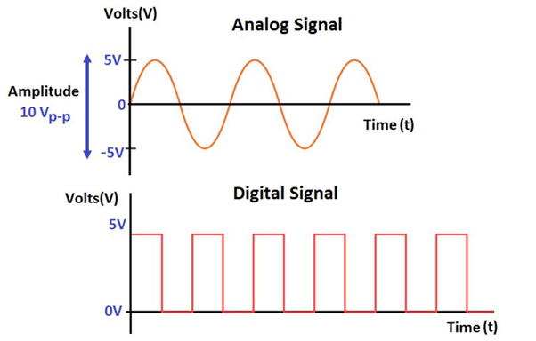
Explain analog & digital signals
Add circuit diagram
5) Final project advance
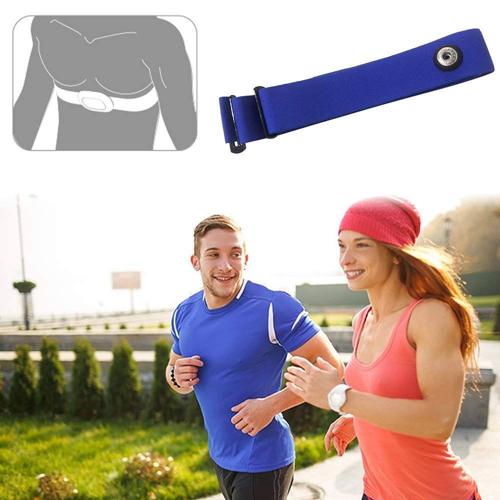
Running
Explore devices
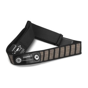
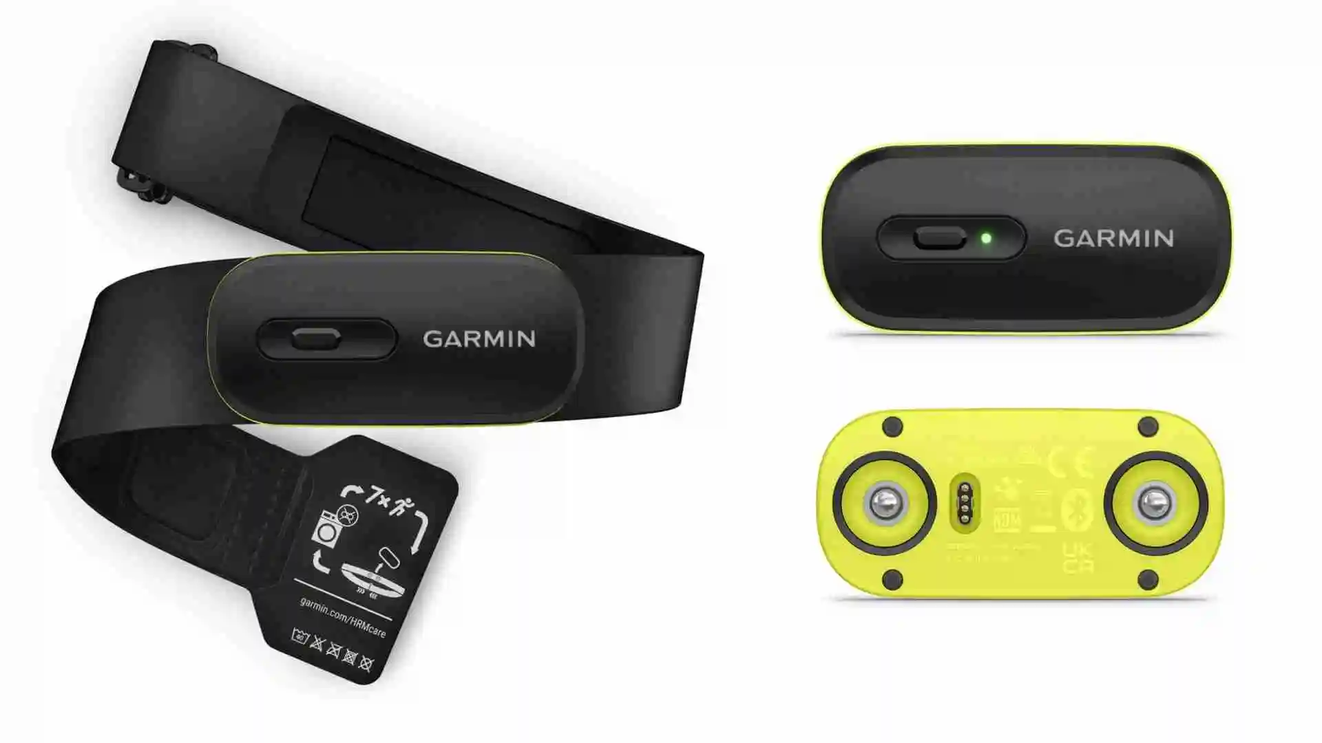
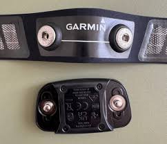
Found more band for runners
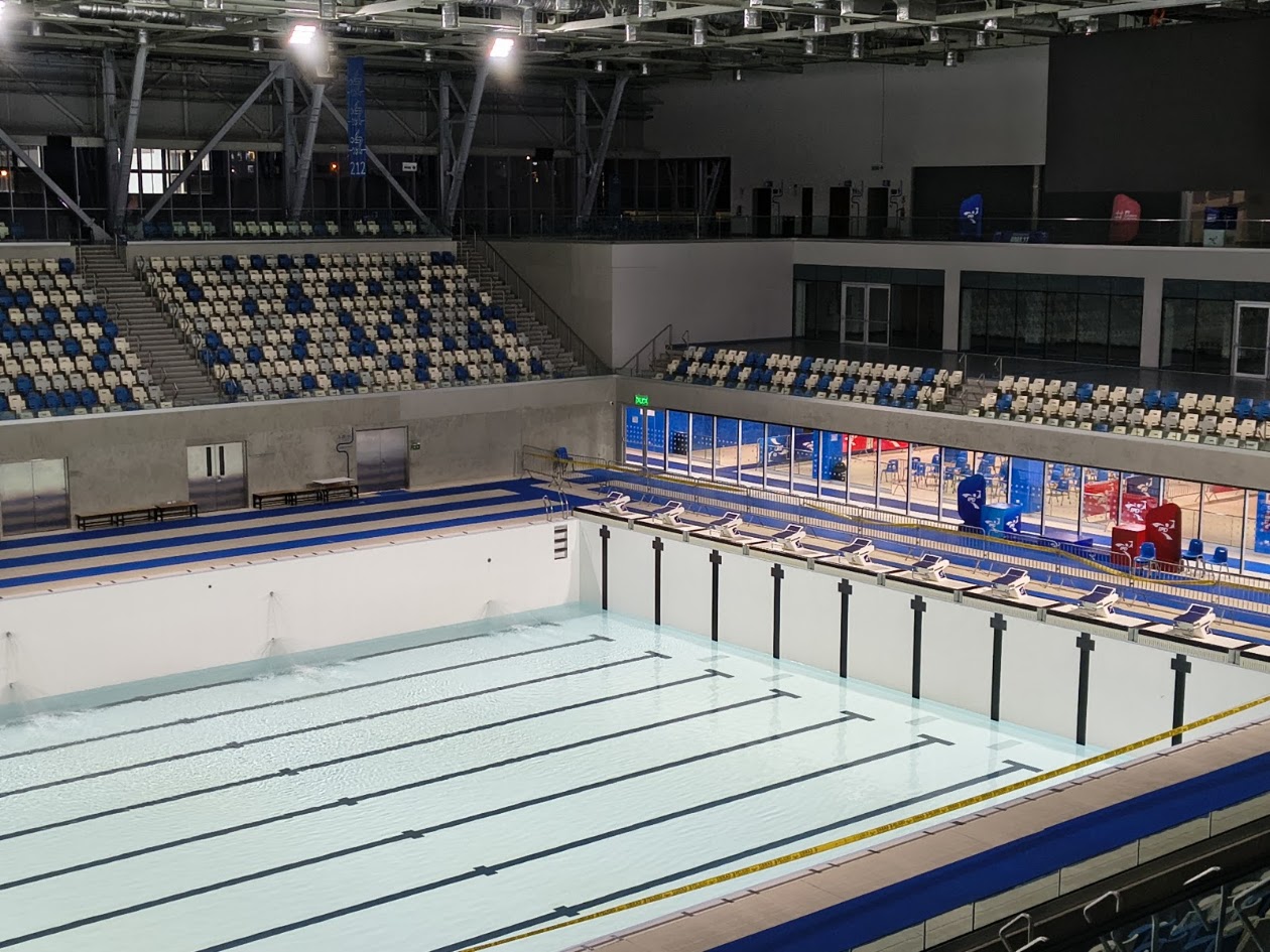
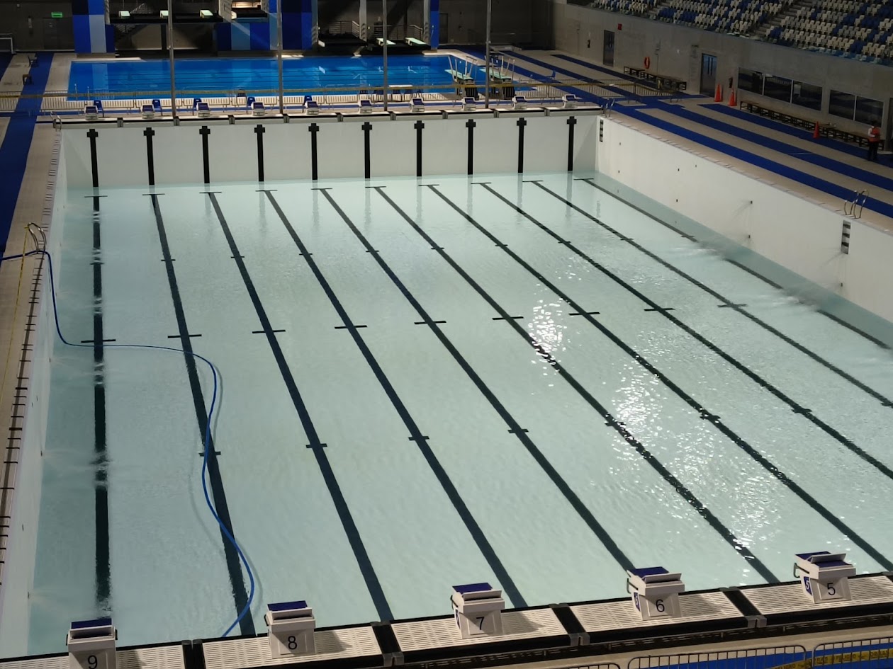
Swimming
Explore an olympic pool
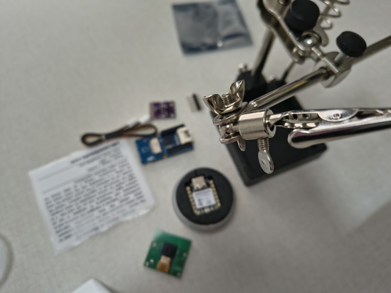
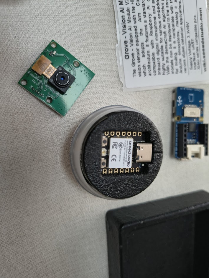
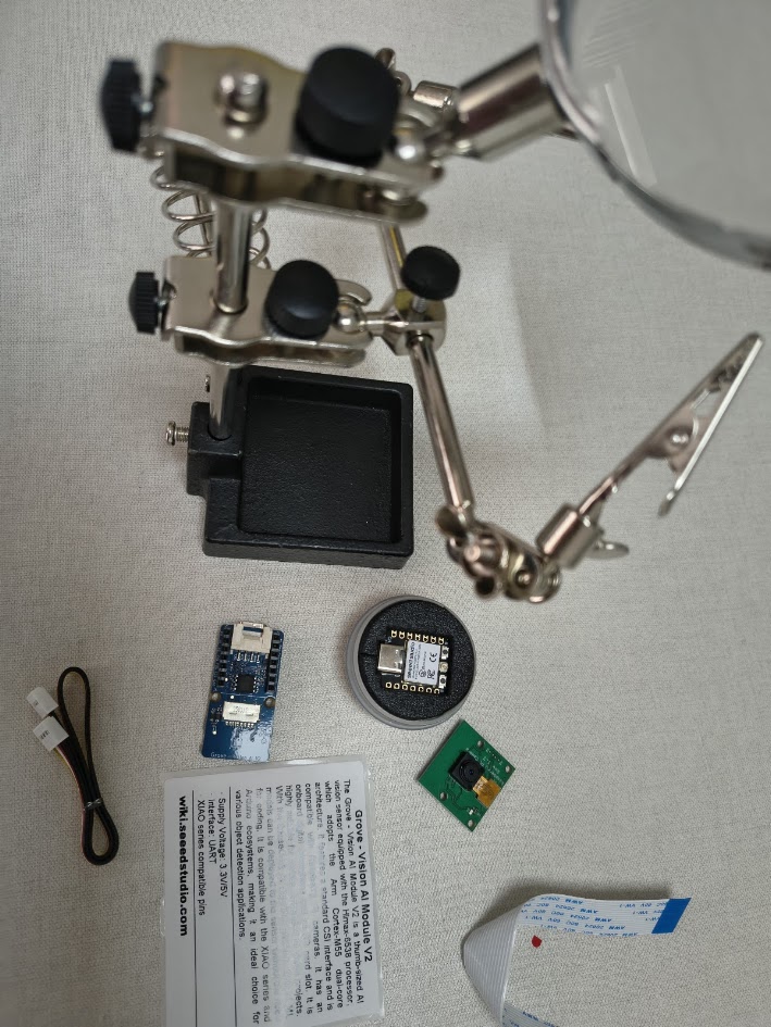
Devices
Grove Vision AI V2-HX6538 Processor
Camera CSI OV5647
Color and gesture sensor - RGB GY-9960-3.3 APDS-9960
6) Final results
- Linked to the group assignment page
- Documented what you learned
- Documented your design and fabrication process
- Explain how your code works
- Explained any problems and how you fixed them
- Include original design filess and source code
- Included a 'hero shot' of your board
7) References files
We learn how to design, make and test a PCB with sensor. Files: in each section