Assignment requirements
Group assignment
- Use the test equipment in your lab to observe the operation of a microcontroller circuit board (as a minimum, you should demonstrate the use of a logic analyzer)
- Document your work on the group work page and reflect what you learned on your individual page
Individual assignment
- Use an EDA tool to design a development board that uses parts from the inventory to interact and communicate with an embedded microcontroller
Progress status
Test equipment
Use EDA tool
Upload .zip with source files.
1) Introduction
My main goal: survive
2) Equipments and materials
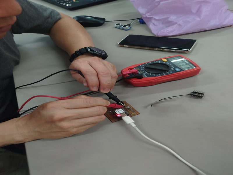
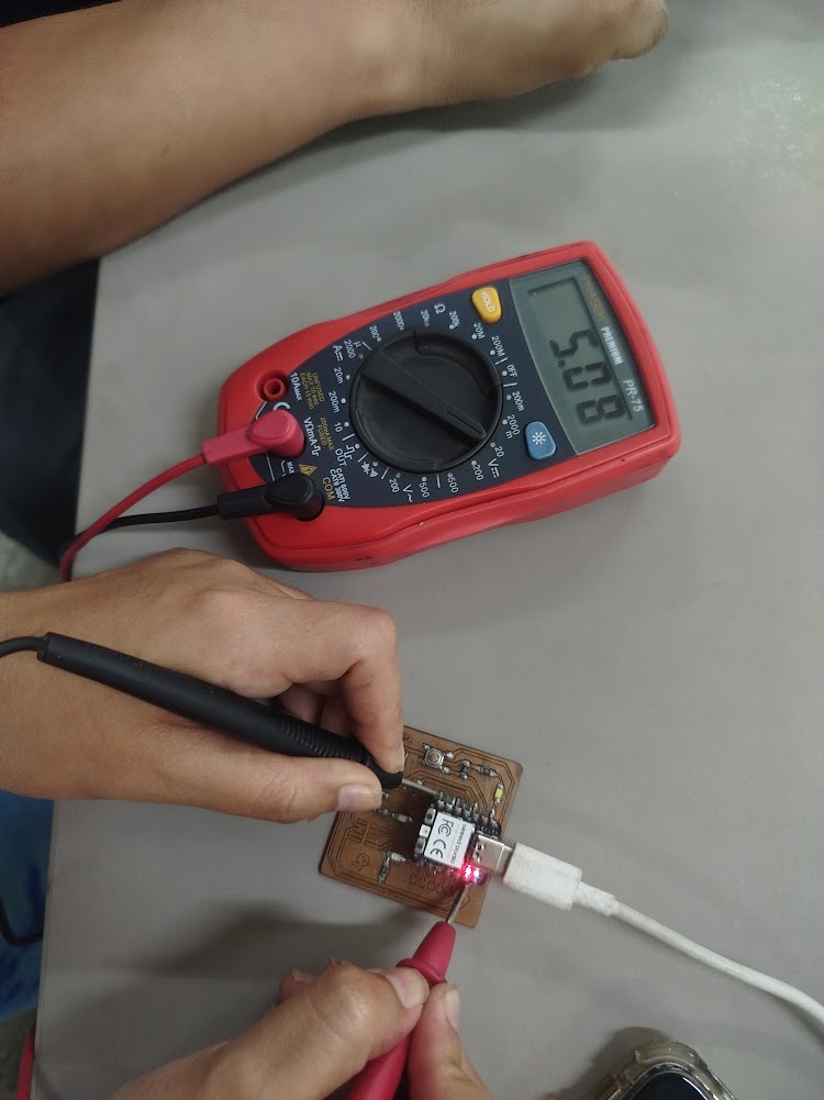
Digital multimeter PR-75
Type: Portable digital multimeter. The PR-75 is a general-purpose handheld digital multimeter designed for basic electrical measurement tasks in electronics and electrical work
Main features:
DC / AC Voltage Measurement up to 600V, Resistance Measurement (Ω), Continuity Test with Buzzer, Diode Test, Current Measurement (mA and 10A), Digital LCD Display, Manual Range Selector
Practical use:
Verify power supply (3.3V and 5V), check continuity between traces, and rule out short circuits before taking measurements with an oscilloscope
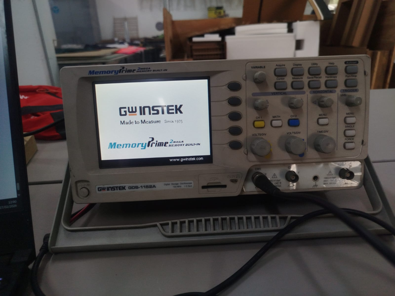
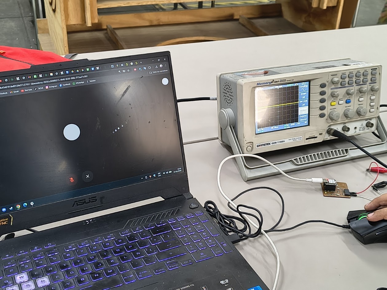
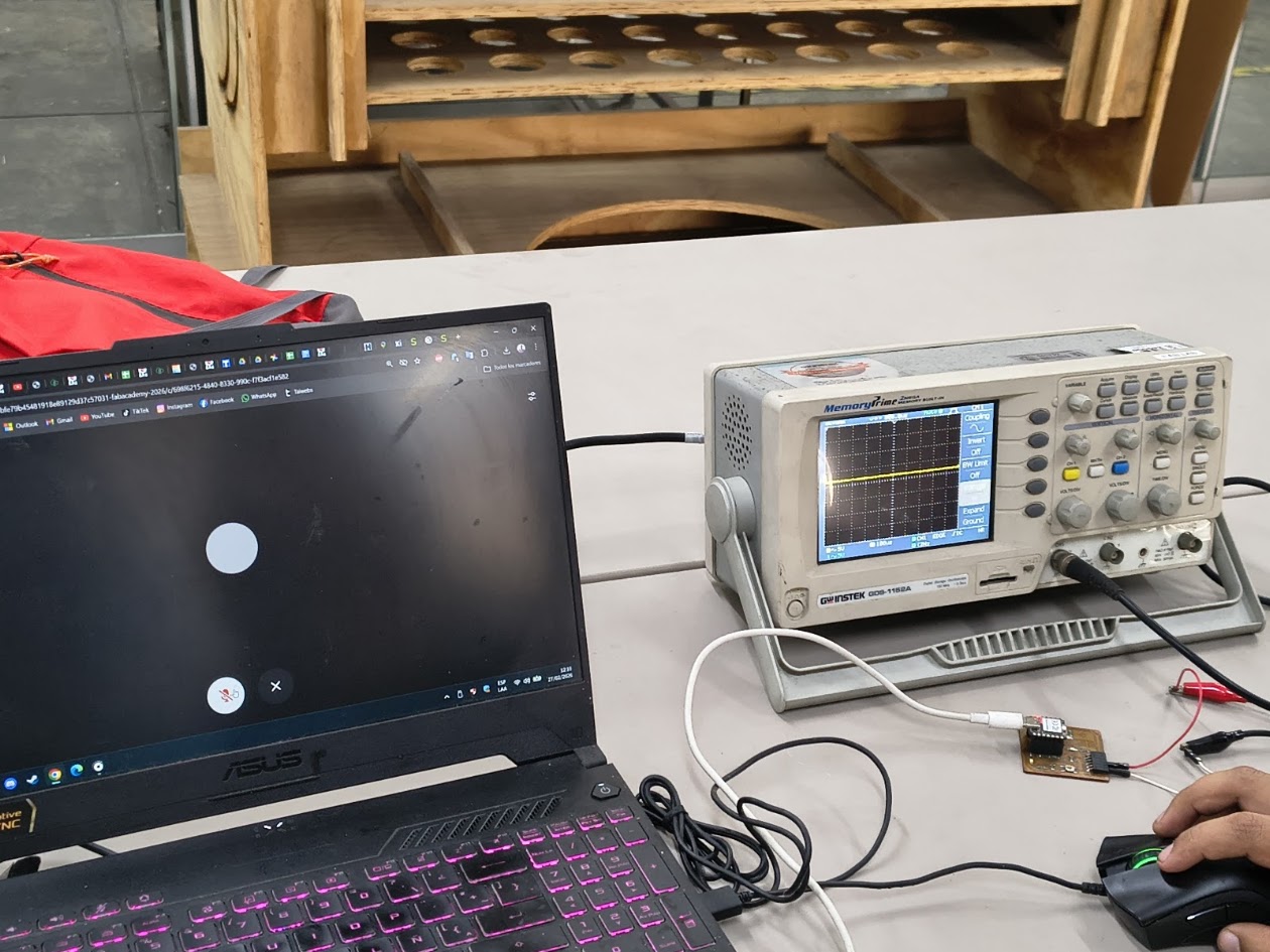
Digital oscilloscope (GW Instek GDS-1152A)
Type: Two-channel digital oscilloscope (150 MHz, 2-channel model) for electronics labs. It captures and stores waveform data, letting you view, measure, and analyze electronic signals visually
Main features:
2 channels (CH1 and CH2), autoset function (for quick signal adjustment), VOLTS/DIV and TIME/DIV controls, trigger system (for signal stabilization), waveforms and measuring values such as voltage and frequency
Practical use:
Verify signals over time (for example, a square wave or a PWM signal), test: microcontroller's output pin, digital signal (square wave), microcontroller code and pins
Materials
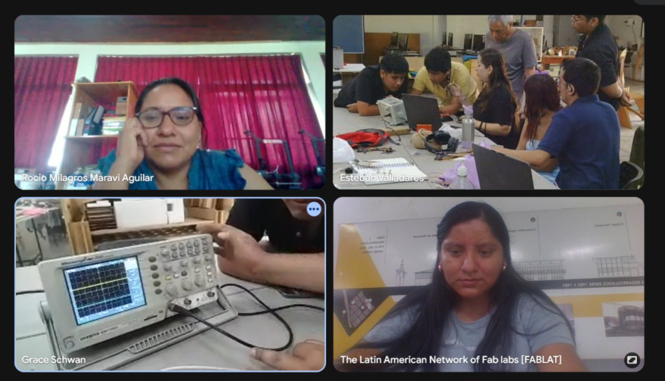
4) Group assignment results
For more details visit Fab Lab Peru Week 6 Group assignment
Review references
Multimeter, oscilloscope, Xiao ESP 32 C32 and others
Multimeter
Multimeter with Xiao ESP 32 C32 Seeed Studio Mini, leds, board, usb C charger
Multimeter
Group tests and results
Oscilloscope
Results display
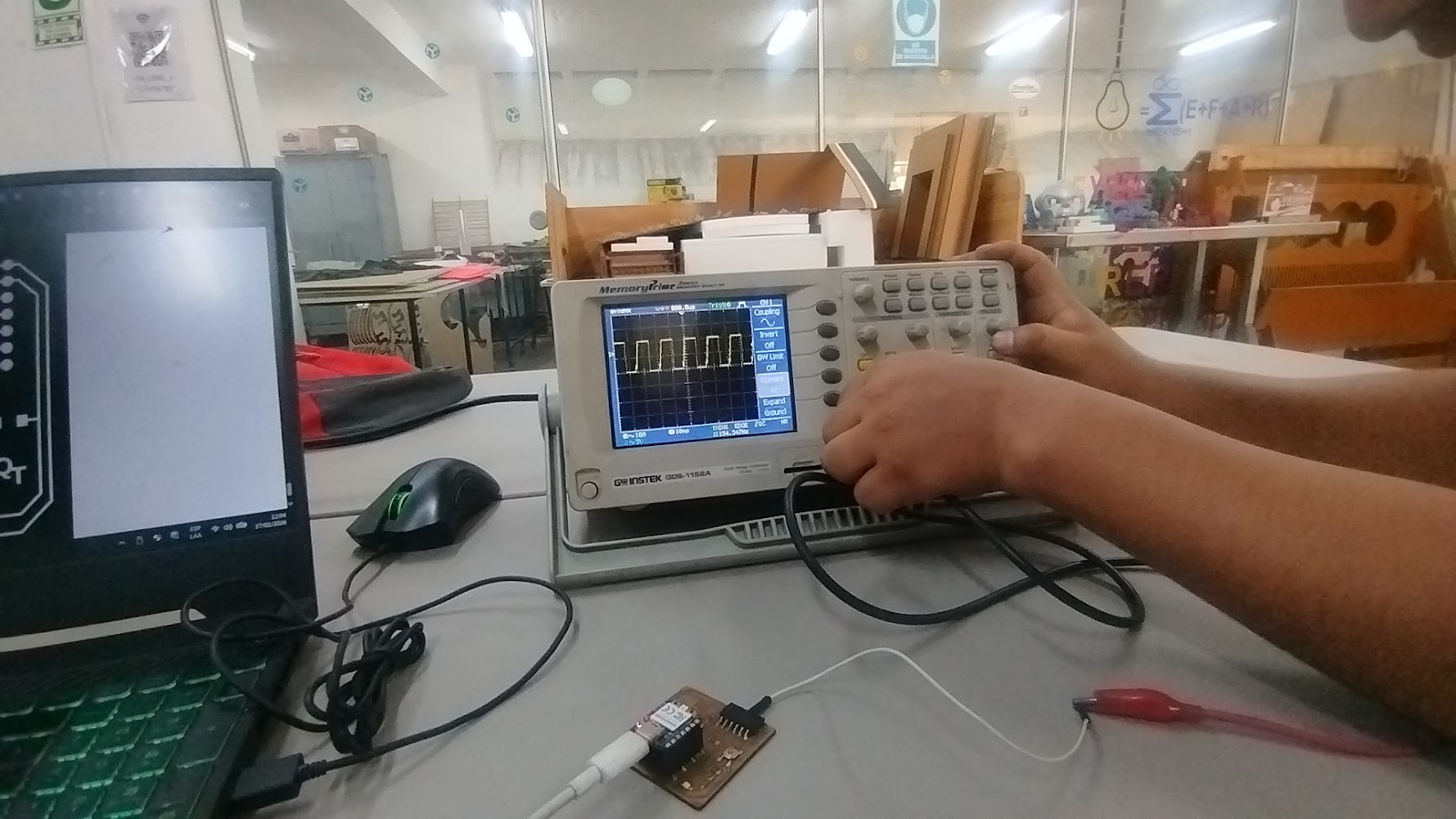
Oscilloscope
Review waves
Oscilloscope
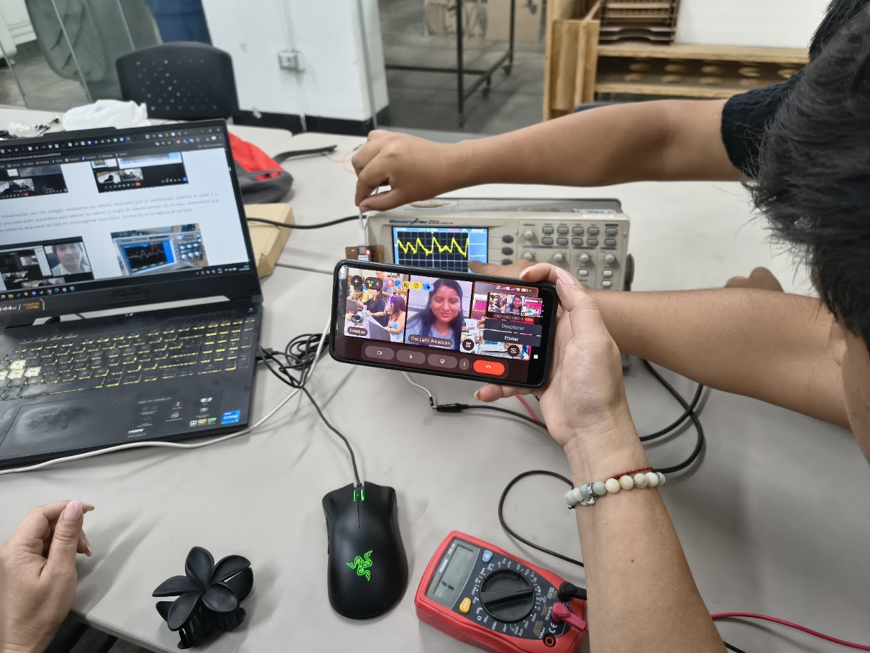
Group results and signals display
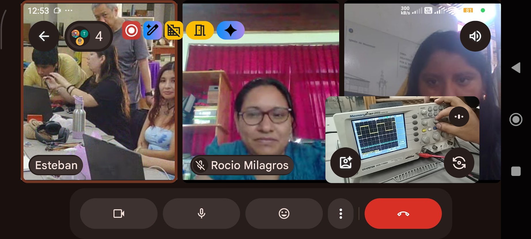
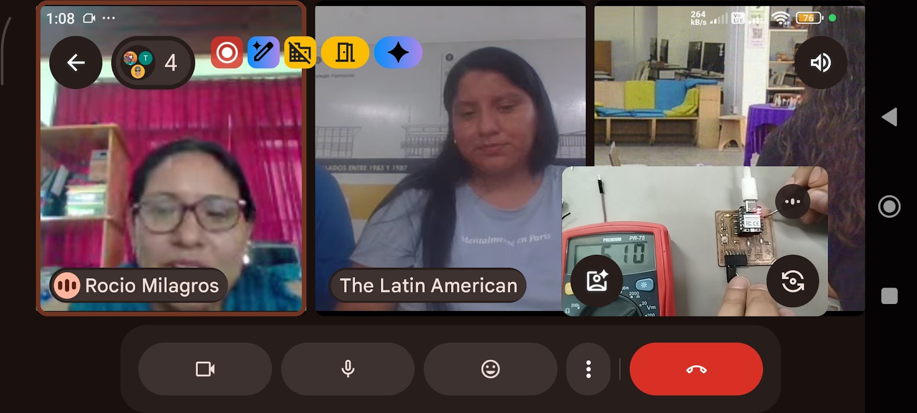
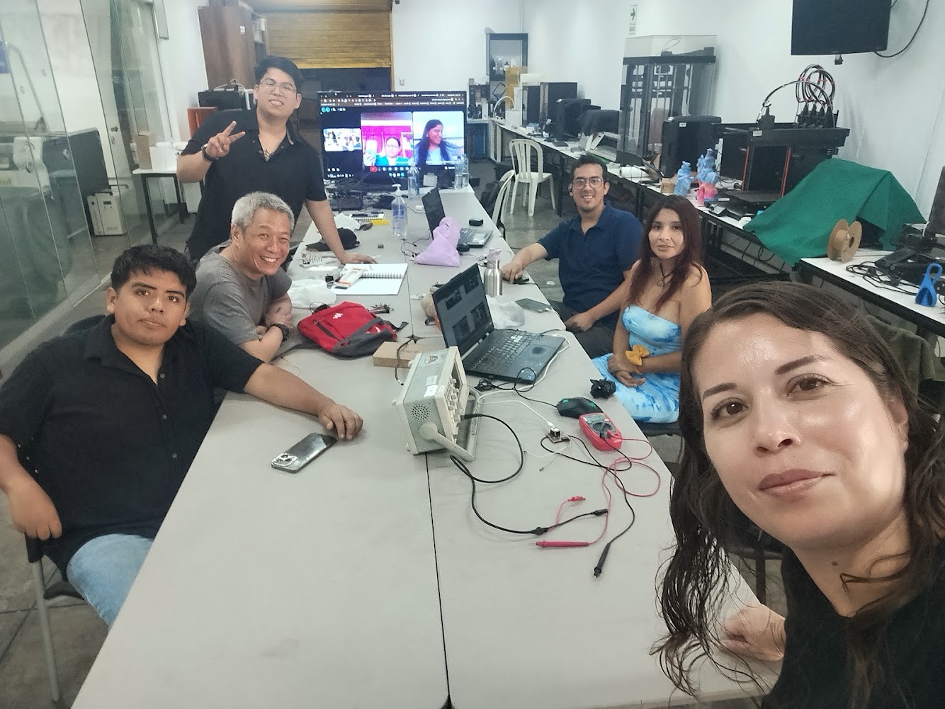
Group at Fab Lab UNI
Group discussion and wrap up
5) Individual assignment
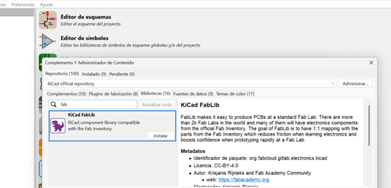
Installing KiCad
Main program and FabLib
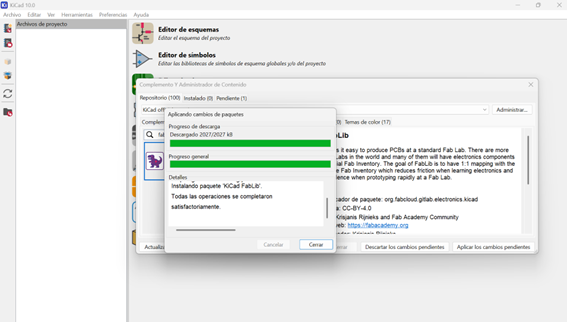
Installing KiCad
Problems with versions
Version 8.0 doesn't work with FabLib
Version 10.0 does not include an update option
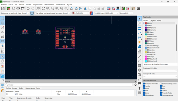
Layout editor
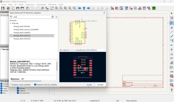
XIAO ESP32-C3
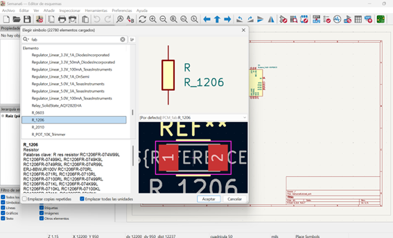
Resistors
LEDs
Components
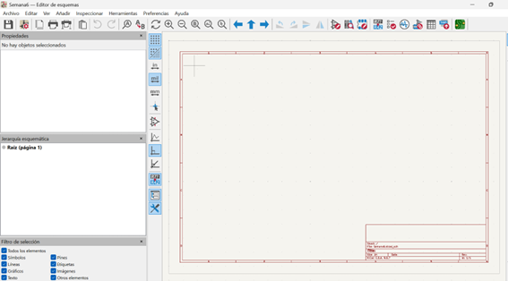
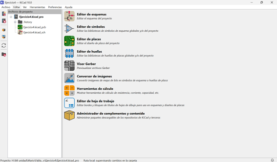
KiCad interface
Initial windows
Main commands
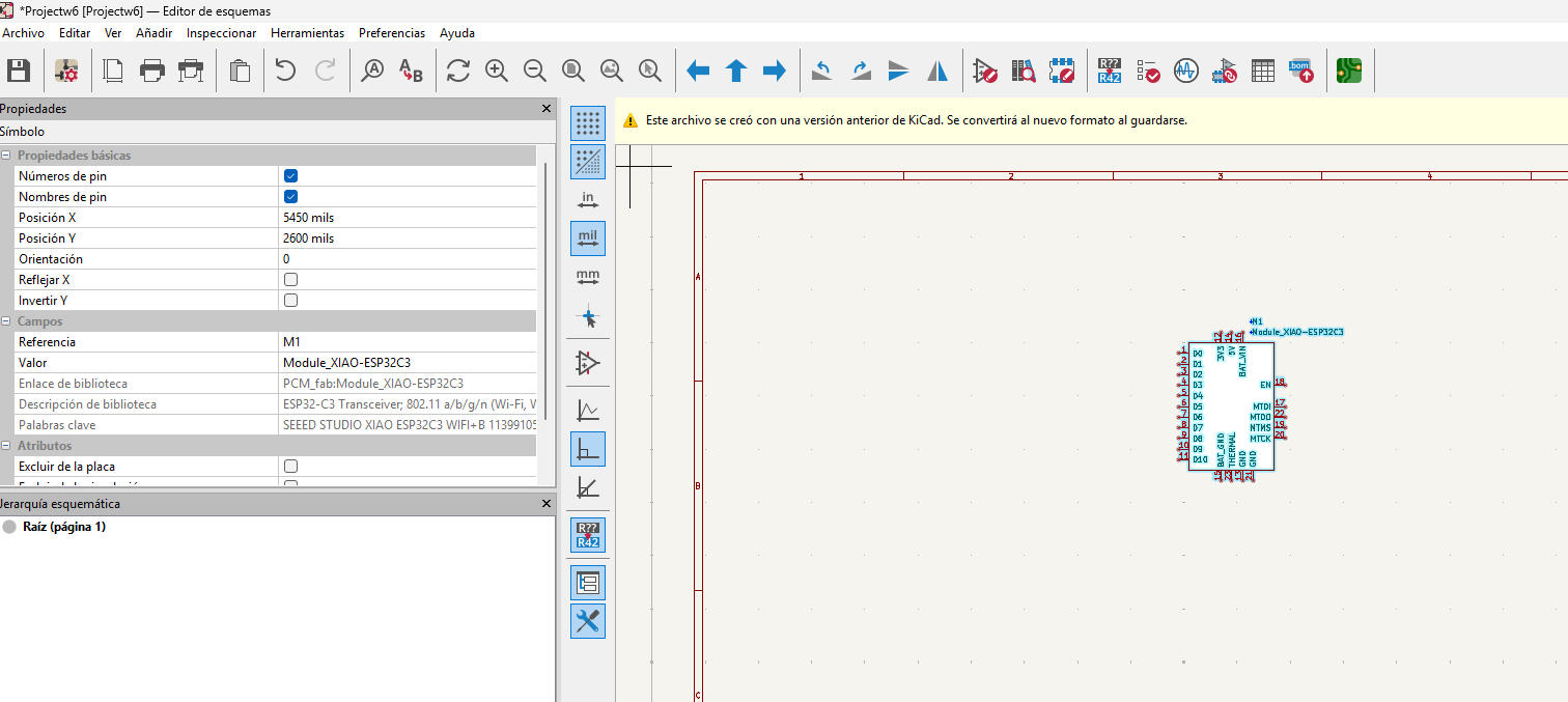
KiCad
XIAO ESP32-C3
KiCad
Resistor - FabLab library R1206
KiCad
LED 1206
KiCad
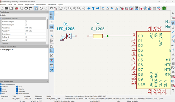
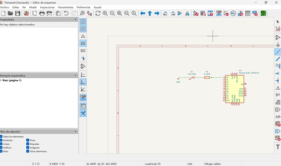
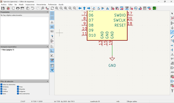
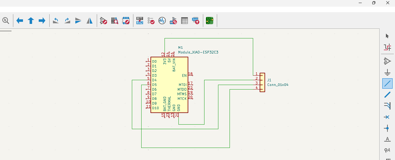
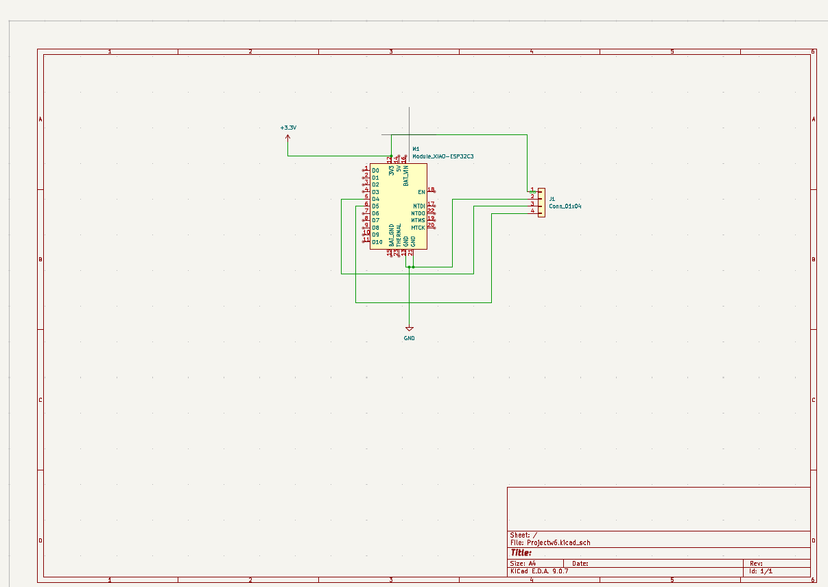
Connecting components

PCB
Main window
PCB
Components placement
Layout
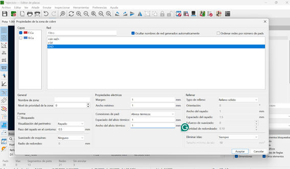
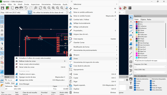
Adding ground
PCB
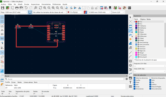
Routing connections
PCB
Cutting the board
PCB
Cutting process
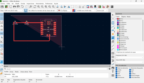
Final PCB Layout
Board, wires, LEDs, buttons, resistors
PCB
Zoom view
PCB
Zoom view
6) Final project progress
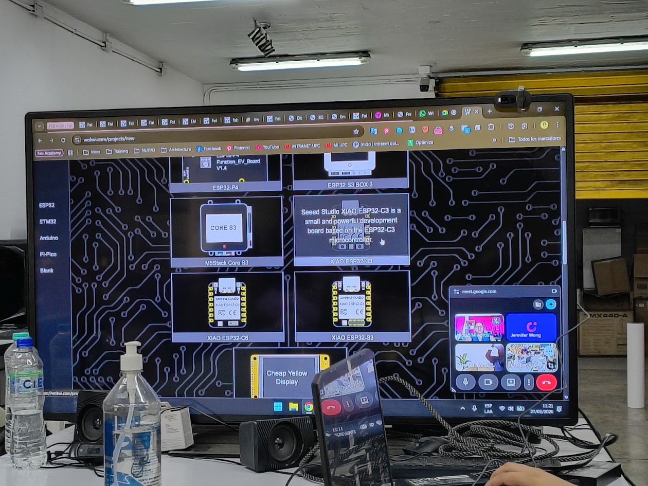
Reviewing uses of Xiao Seeed ESP32-C3
Finding the light
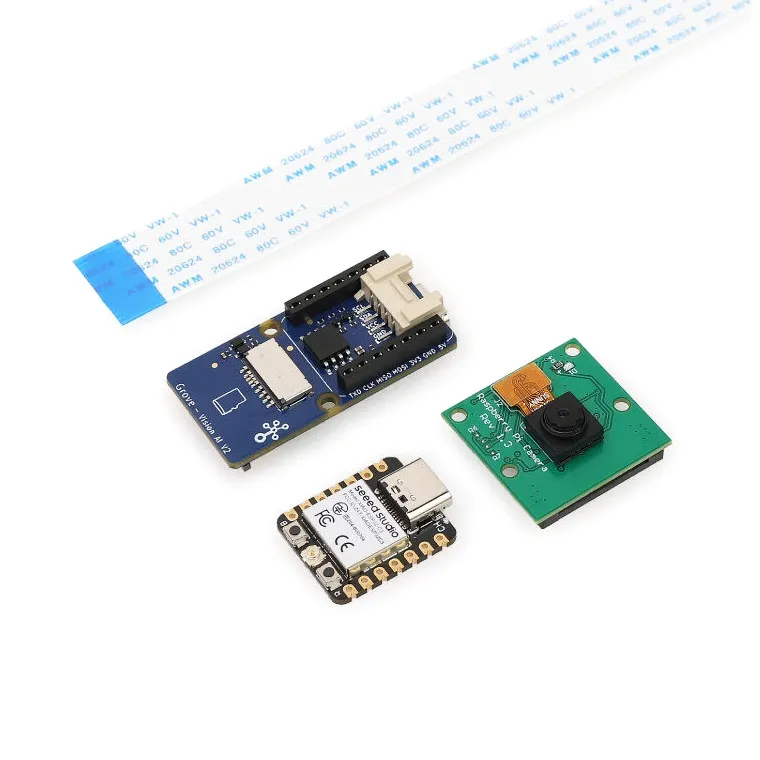
Finding components
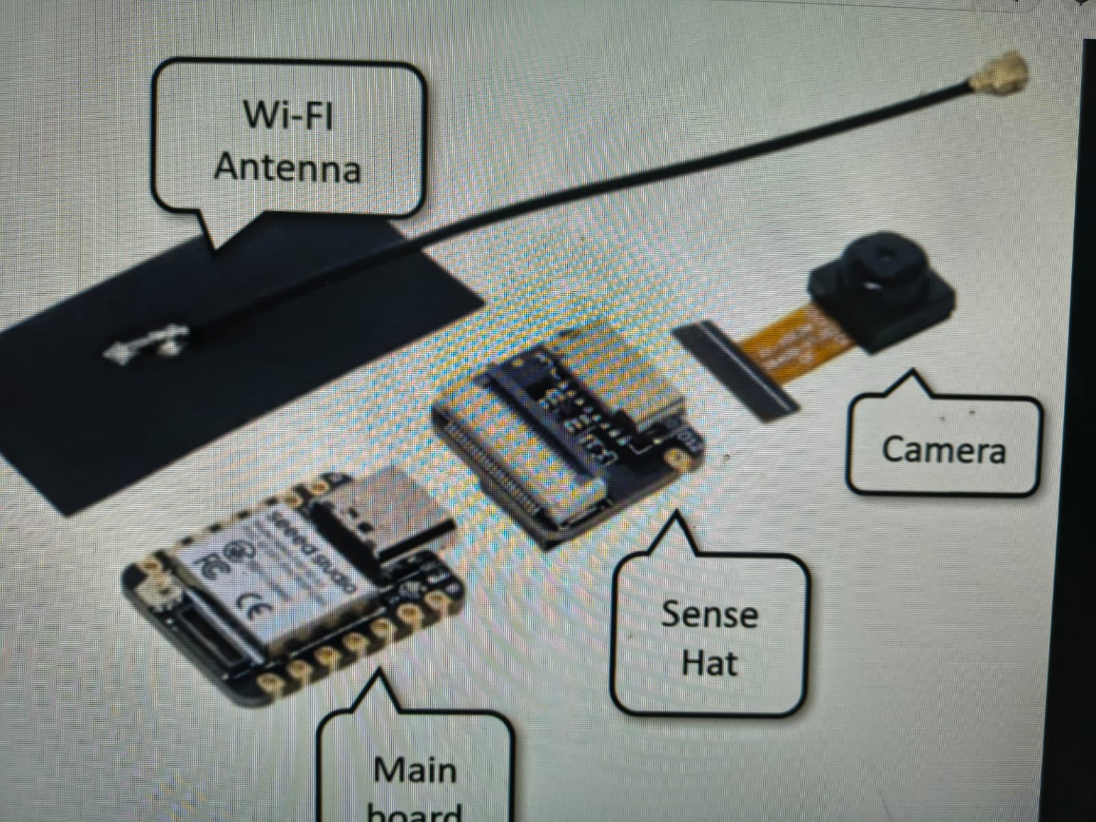
Mainboard: Xiao Seeed ESP32-C3
Sense HAT
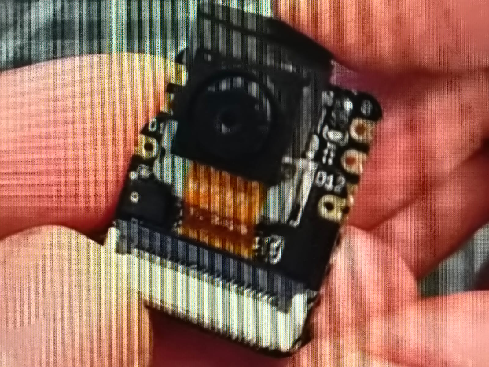
Camera
Finding suppliers
Xiao ESP32-C3 board
Board
Wires
LEDs
Buttons
Resistors
KiCad
After studying KiCad materials
Xiao ESP32-C3
KiCad
Xiao ESP32-C3 board
Camera

KiCad
Xiao ESP32-C3 board
Modelling
Materials
Xiao ESP32-C3 board
Board
Wires
LEDs
Buttons
Resistors
7) Final results
- Linked to the group assignment page
- Documented what you learned in electronic design
- Checked you board be fabricated
- Explain problems and how you fixed them
- Included original files (Eagle, KiCad,...)
- Included a shot hero