Assignment requirements
Group assignment
- Test the design rules for your 3D printer(s)
- Document your work on the group work page and reflect on your individual page what you learned about characteristics of your printer(s)
Individual assignment
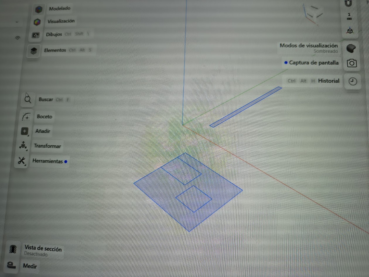
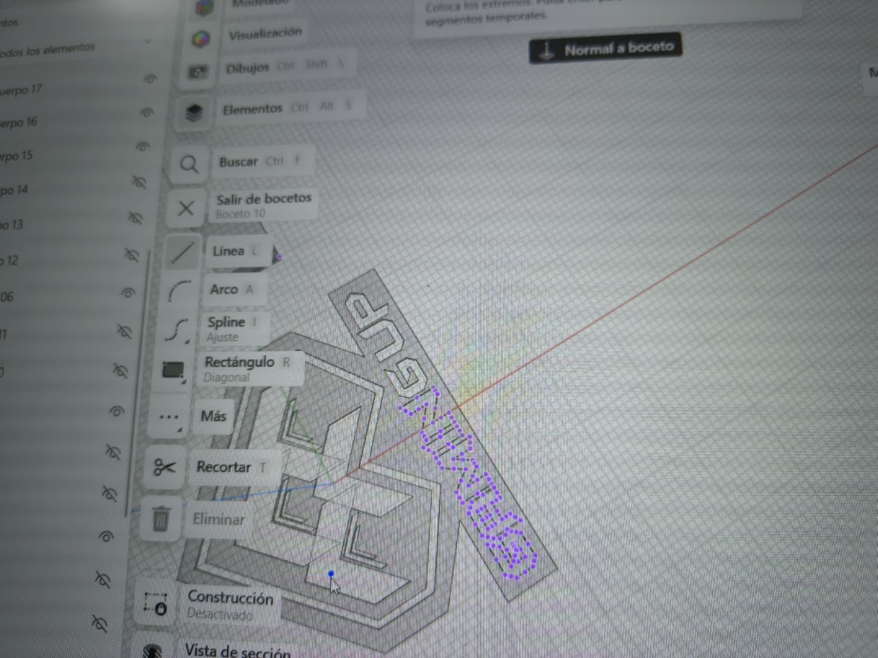
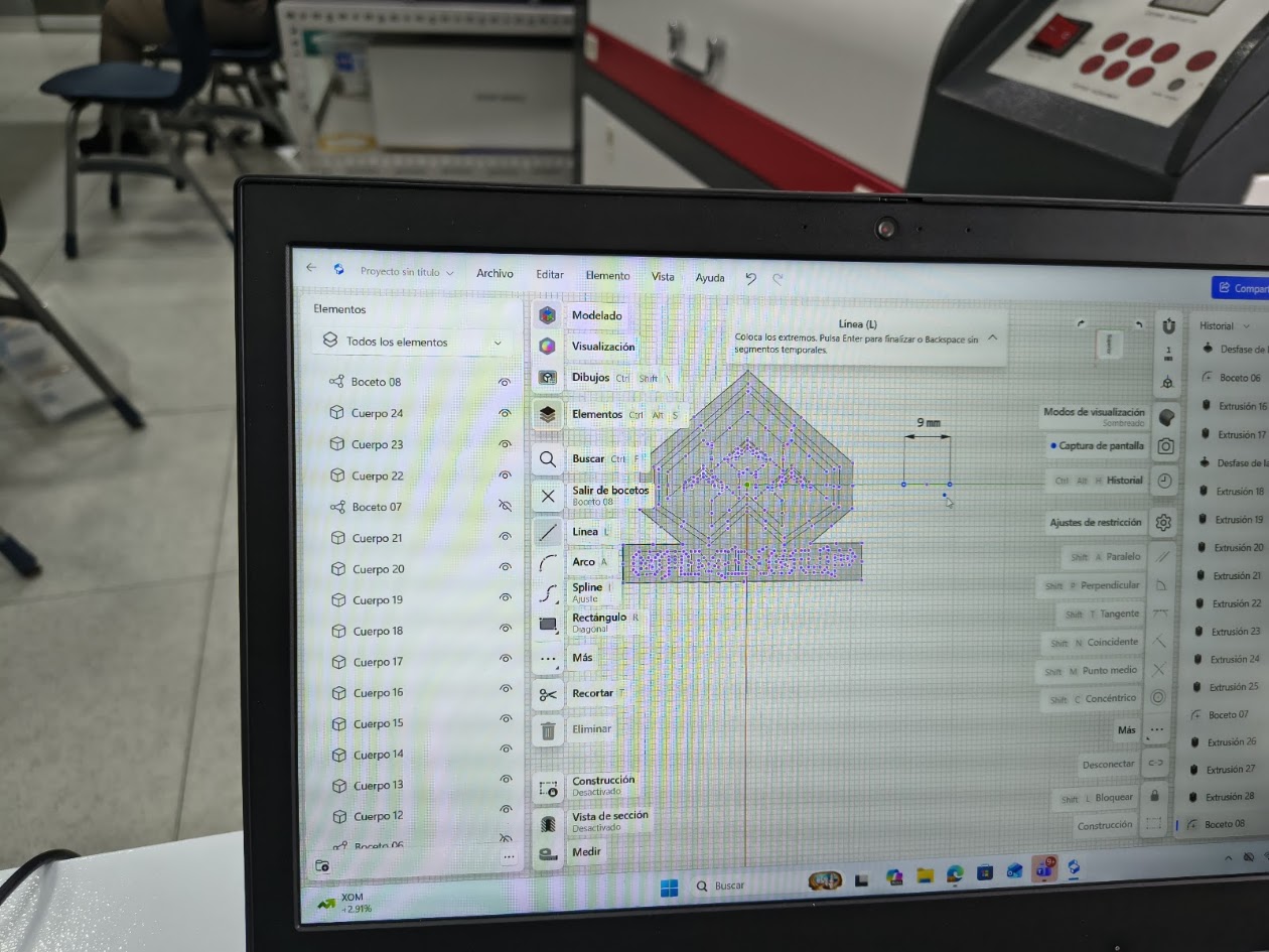
- Design, document and 3D print an object (small, few cm3, limited by printer time) that could not be easily made subtractively
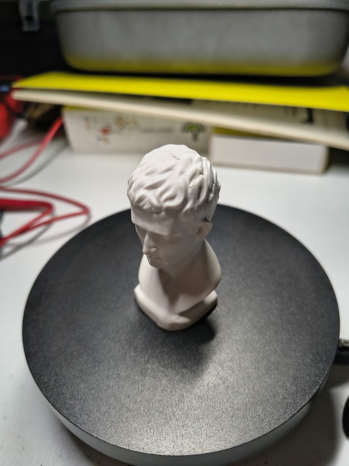
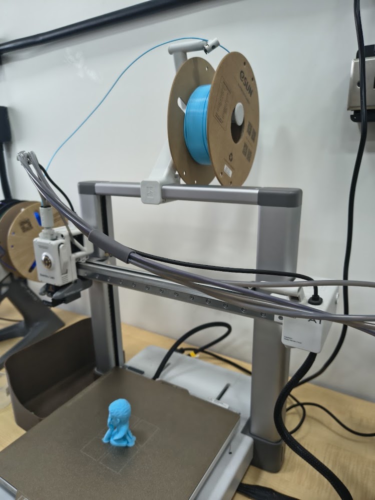
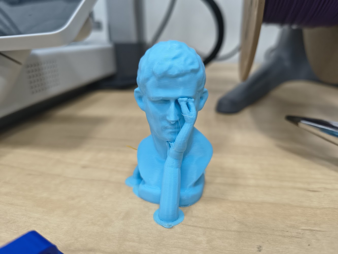
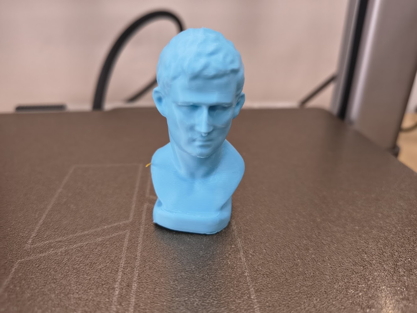
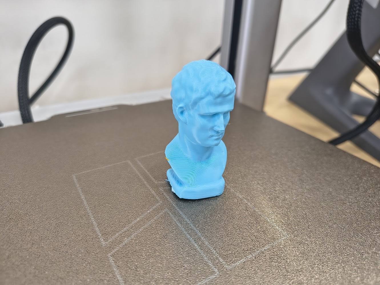
- 3D scan an object (and optionally print it)
Progress status
Design rules for 3D printers
Design, document and 3D print an object
3D Scan an object (optional print it)
Upload source files
1) Introduction
Learn, learn and learn
- Learn 3D printer characteristics
- Interact with the 3D printer
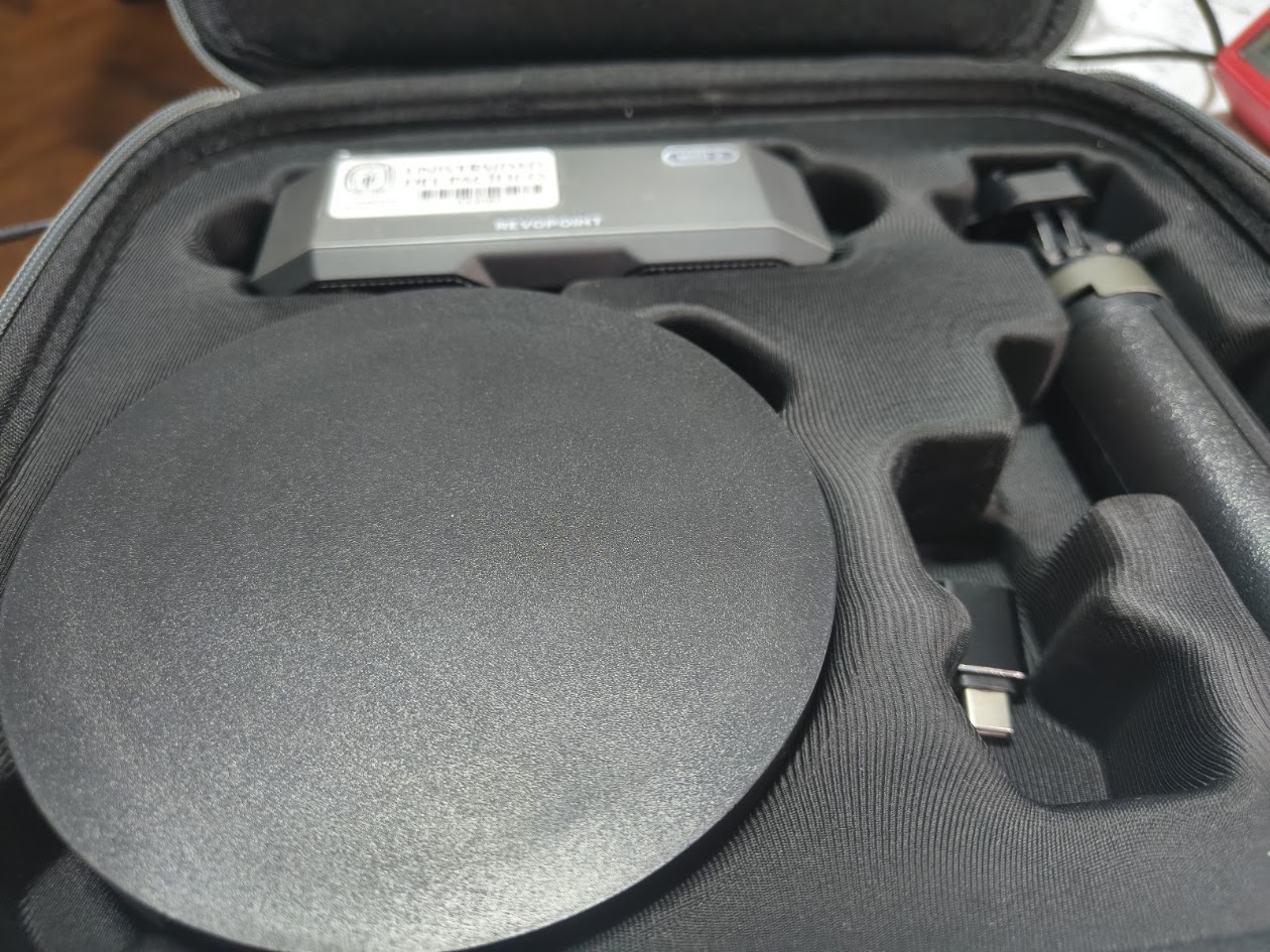
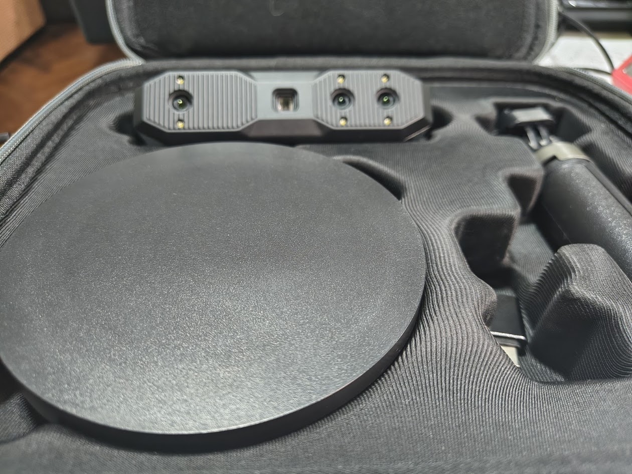
- Learn how to use the scanner
2) Group assignment - 3D Printer characterizarion
For more details visit Fab Lab Peru Week 5 Group assignment
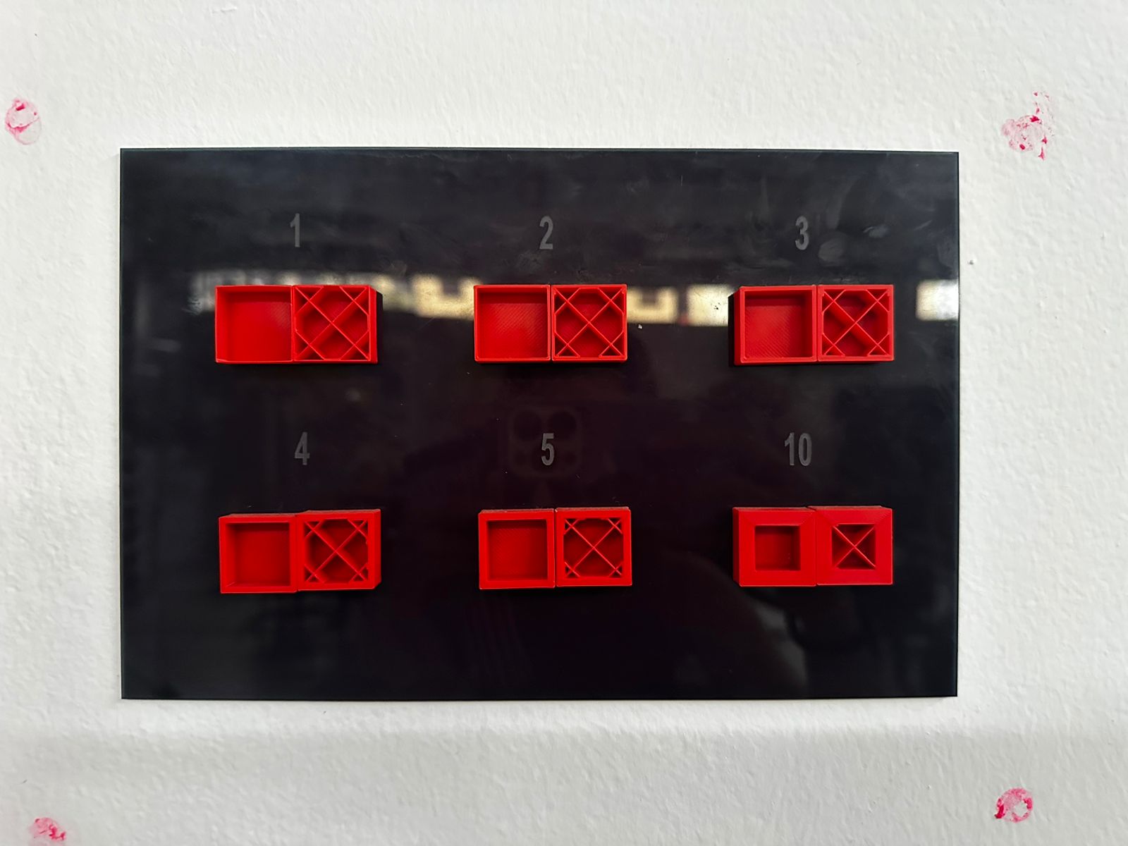
The objective of this group activity was to evaluate and characterize the printing capabilities of the 3D printer available in the laboratory. For this purpose, a calibration test model designed to evaluate multiple characteristics of the printing process was used
The model used was the All-in-One 3D Printer Test, which allows the analysis of different printing parameters such as overhangs, bridging, assembly tolerances, dimensional accuracy, and fine detail reproduction
These tests help to understand the fabrication limits of the printer and establish appropriate design criteria for future digital fabrication projects
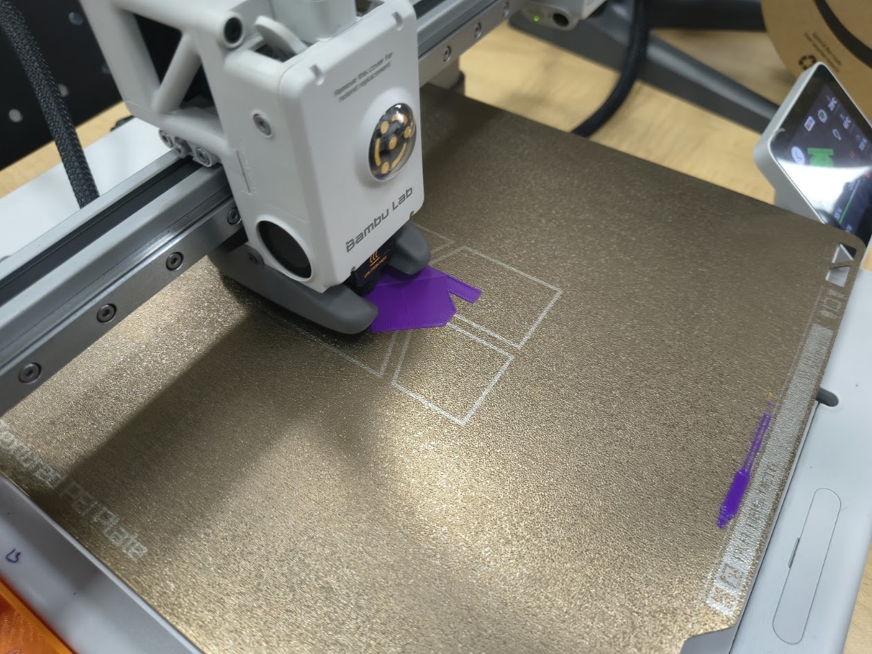
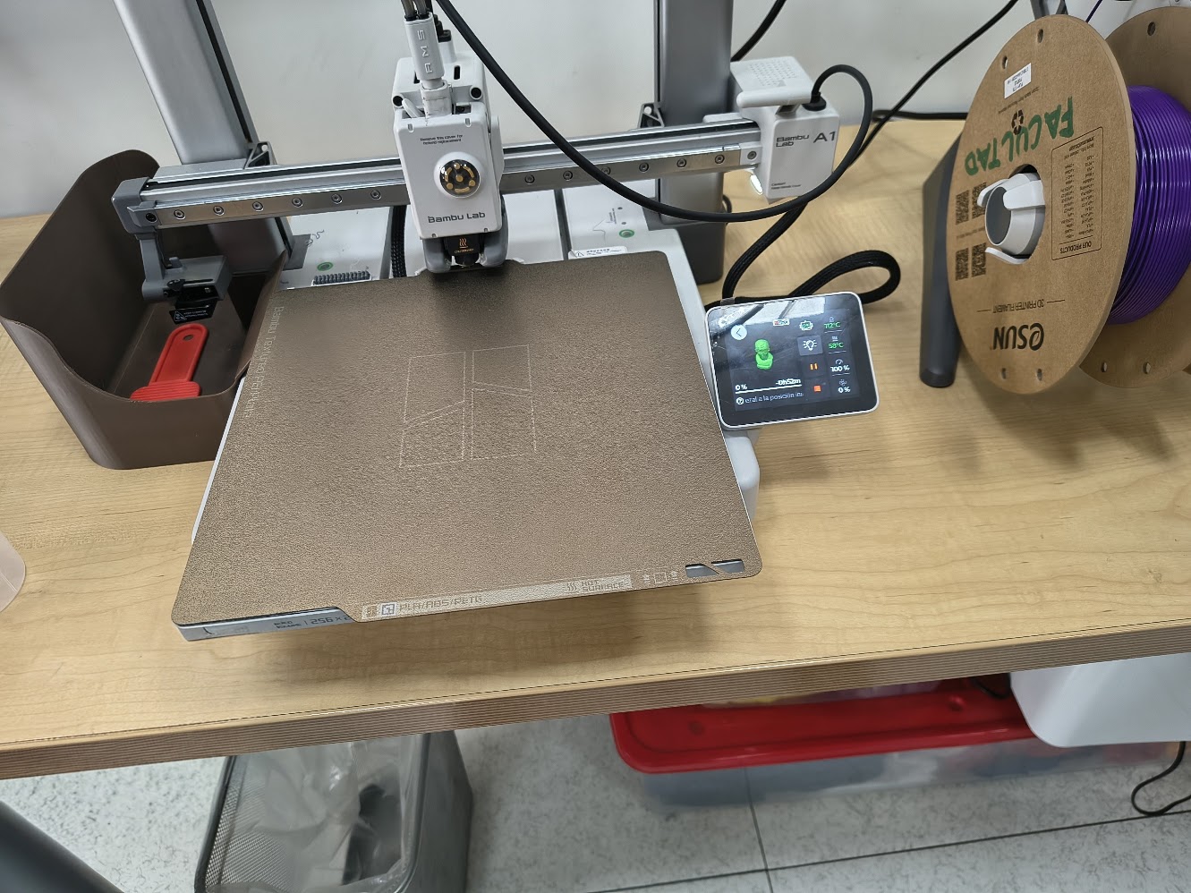
Printer used
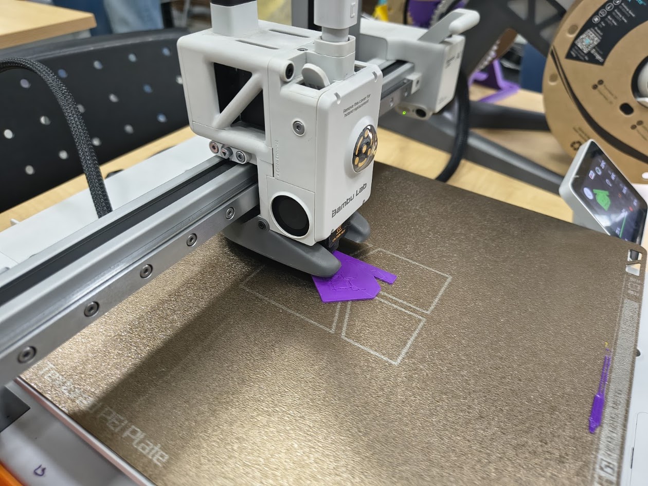
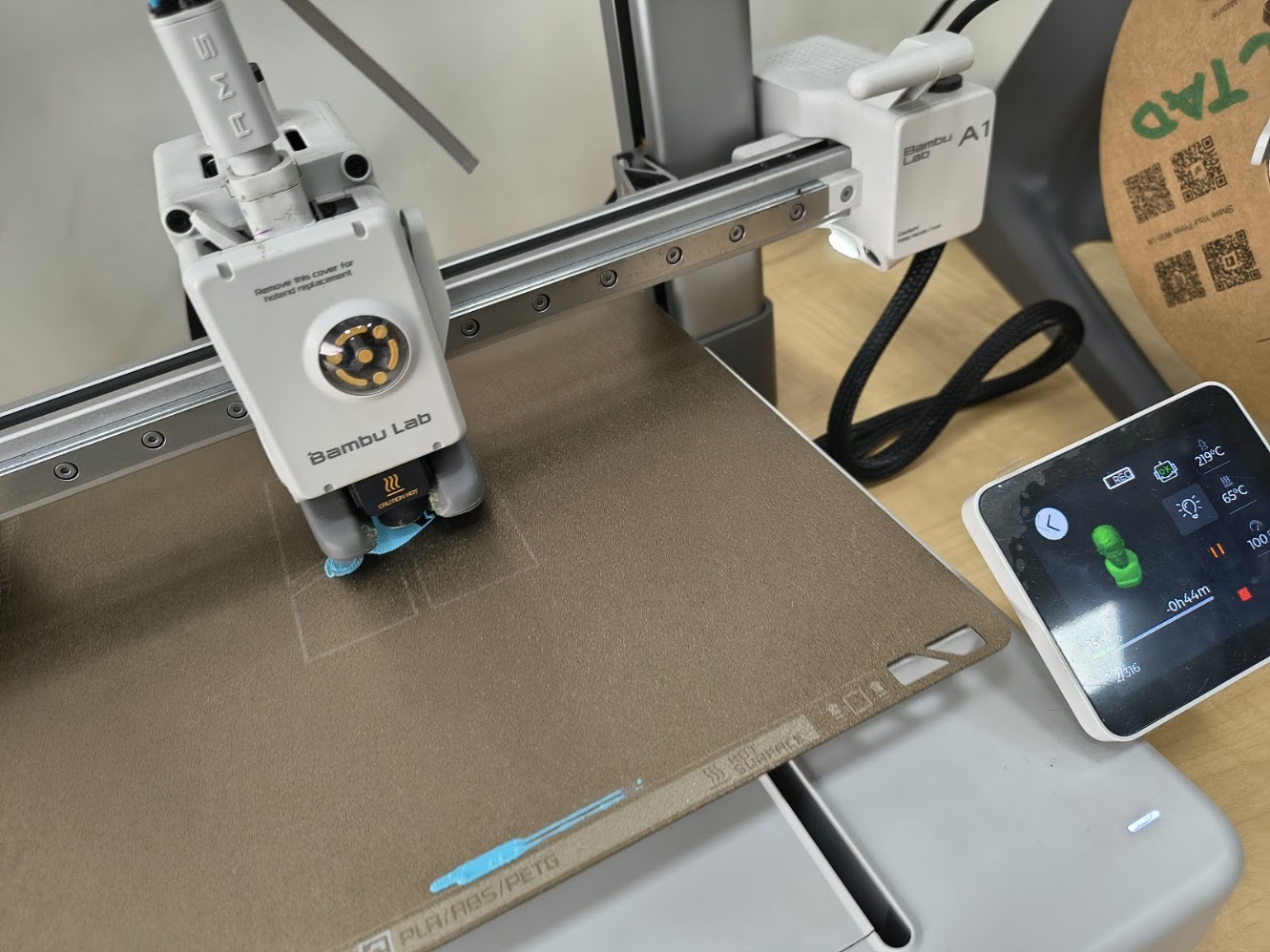
During the activity we used a Bambu Lab A1, a 3D printer based on FDM (Fused Deposition Modeling) technology
In this process the thermoplastic material is melted and deposited layer by layer until the object is formed
The main characteristics of the printer are:
- Technology: FDM
- Direct drive extrusion system
- Automatic bed leveling
- Optimized flow and speed control
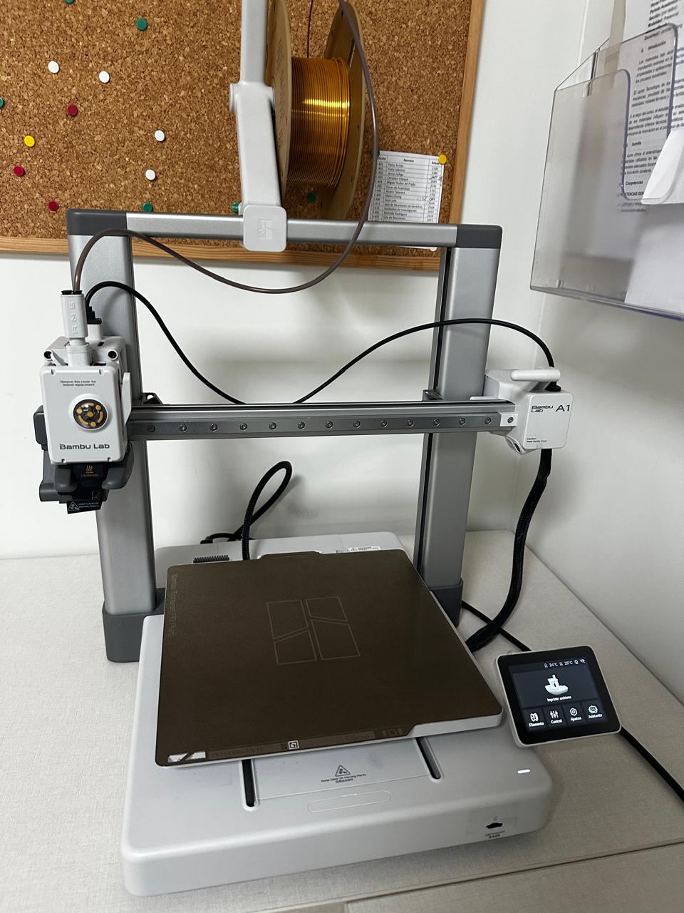
The material used for the test was PLA due to its ease of printing and dimensional stability
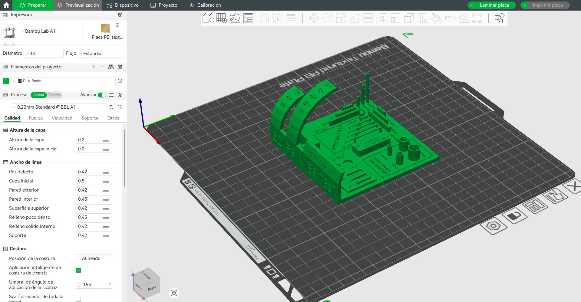
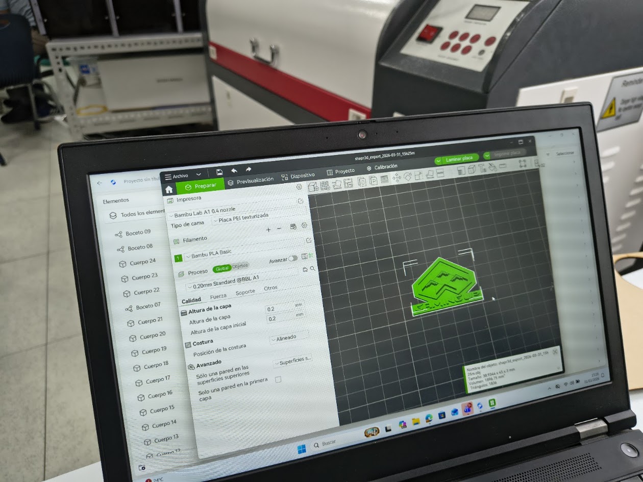
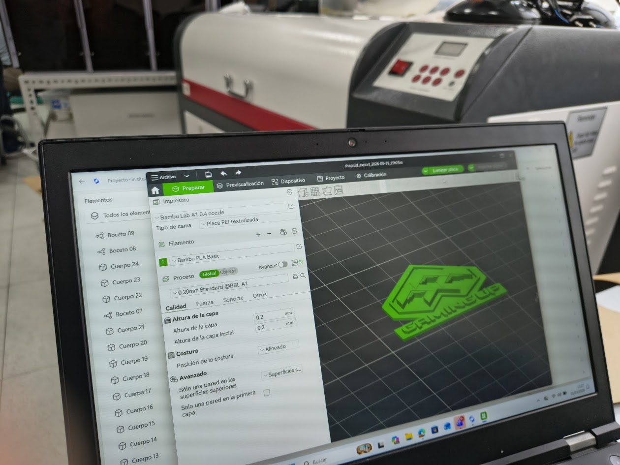
Printing configuration
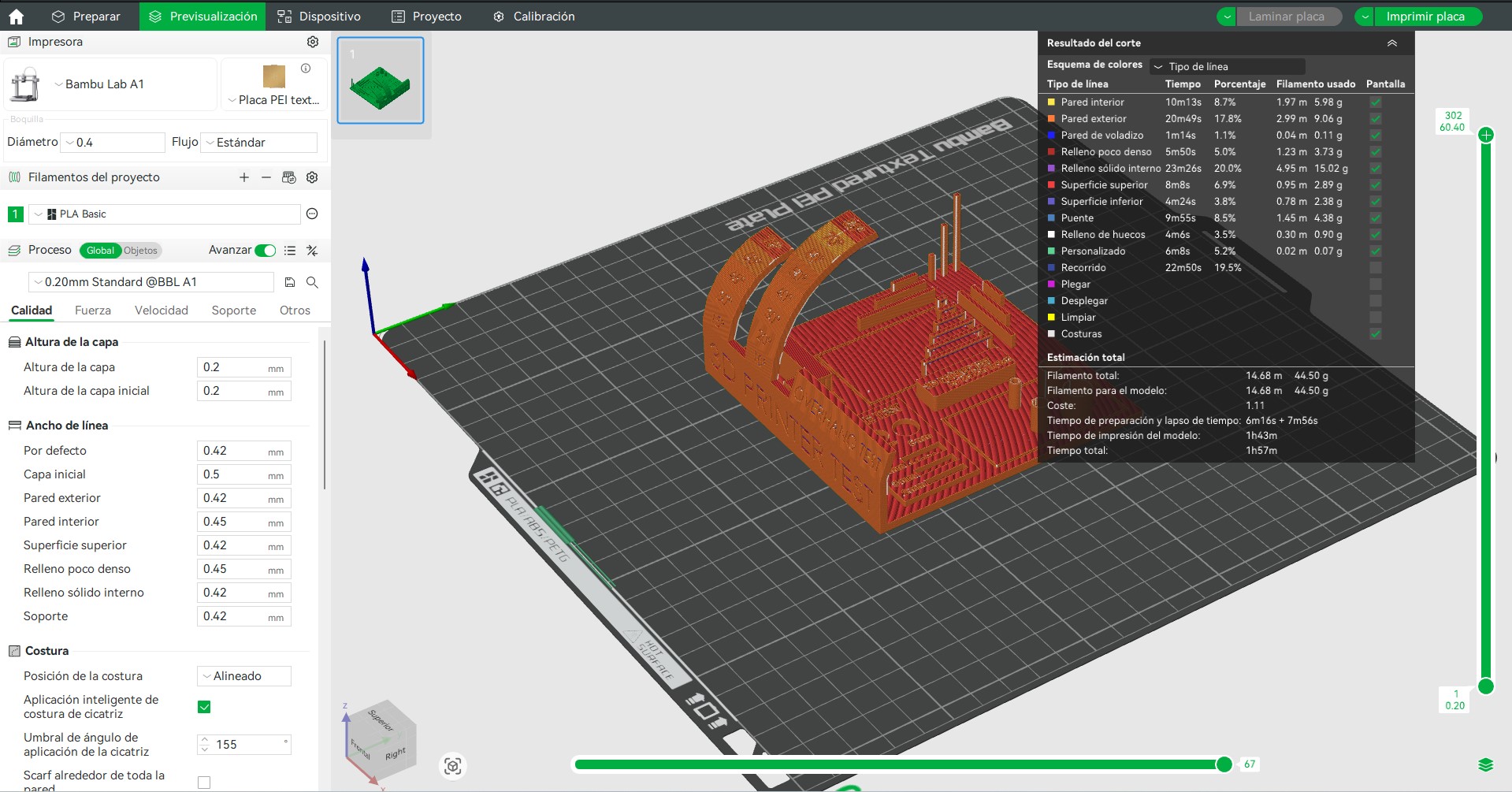
To maintain consistent conditions during the test, standard printing parameters were used on the Bambu Lab A1
Parameters used:
- Material: PLA
- Layer height: 0.2 mm
- Nozzle temperature: 200 °C
- Bed temperature: 60 °C
- Print speed: 60 mm/s
- Supports: disabled
- Infill: 15 %
These parameters allow the evaluation of the printer capabilities without applying specific optimizations for each test.
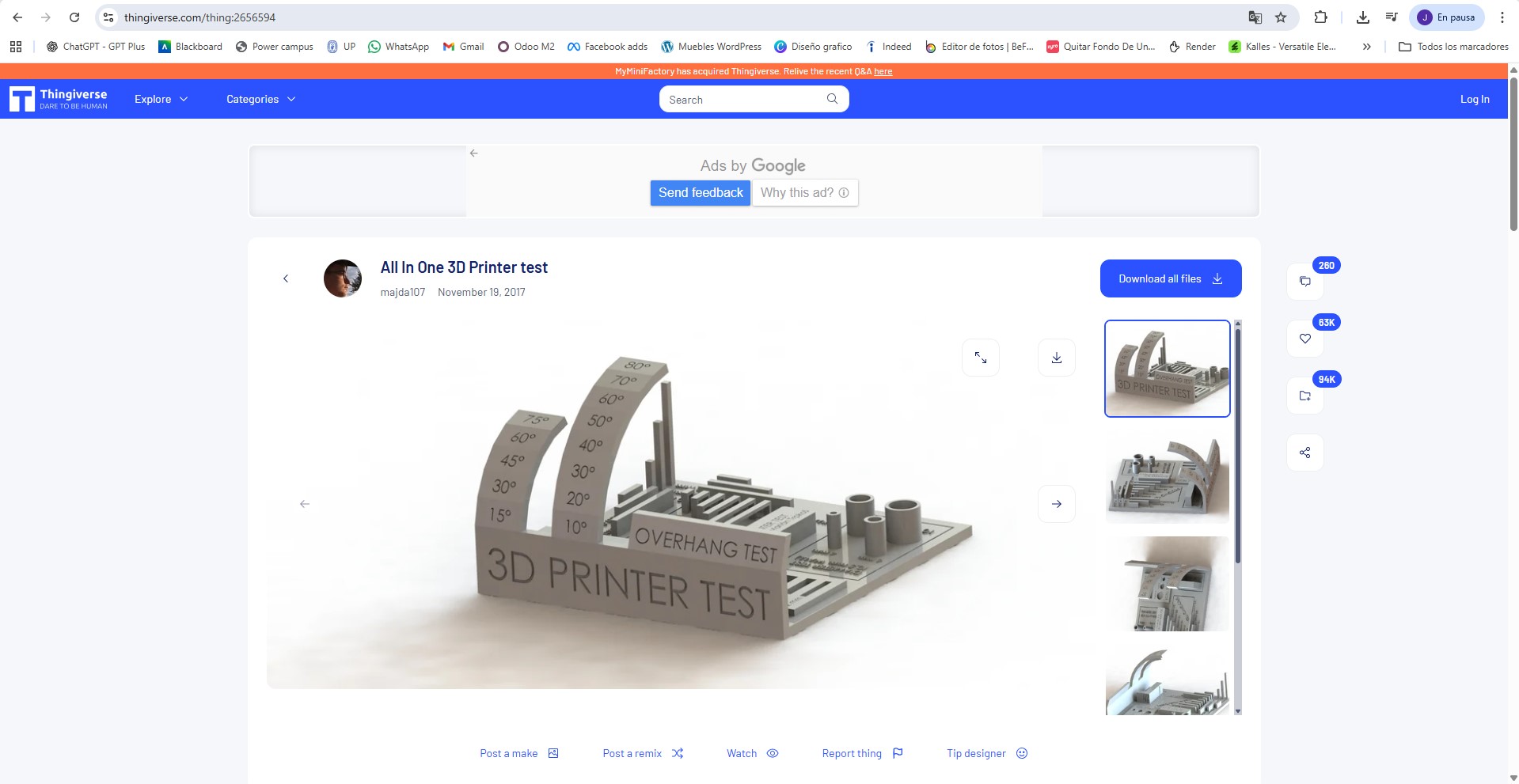
Test model
To characterize the printer we used the All-in-One 3D printer test model
This model is designed to evaluate multiple printing characteristics within a single piece, allowing a quick analysis of the printer performance
The model includes:
- overhang tests
- bridging tests
- assembly tolerances
- fine detail tests
- dimensional accuracy
Tests performed
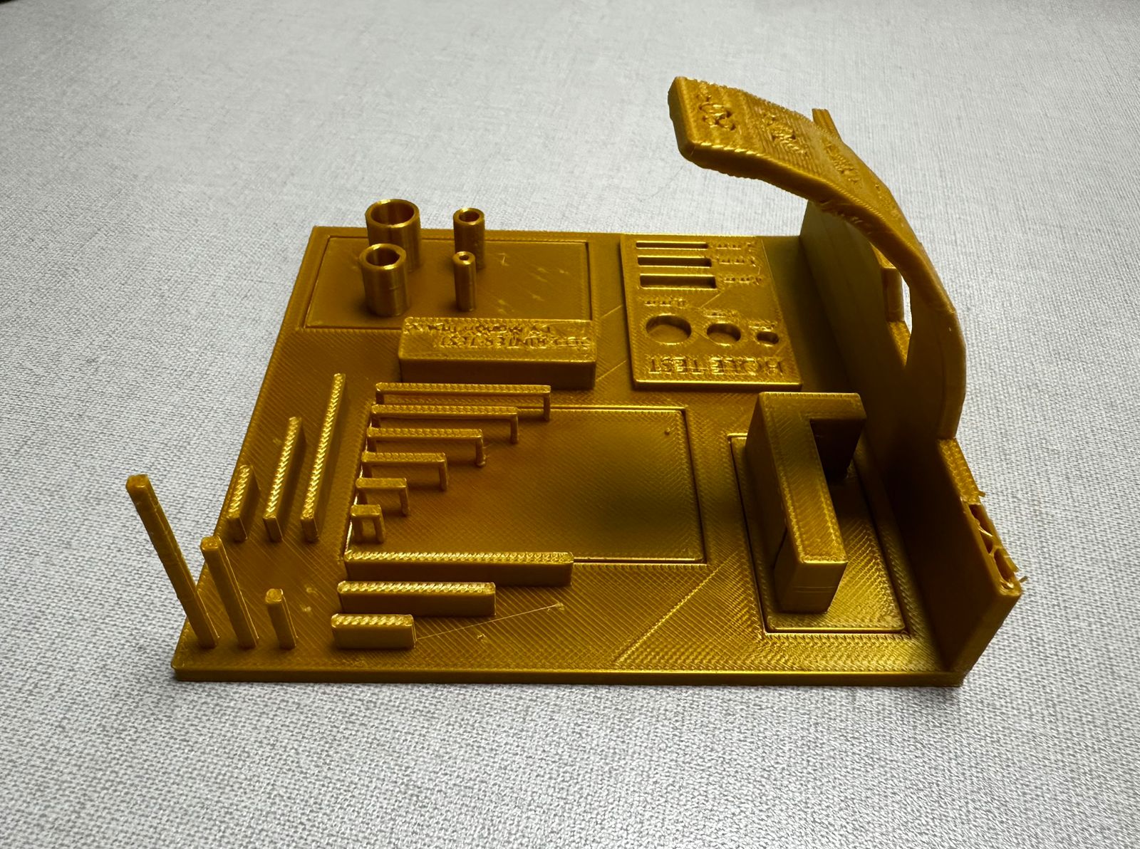
Observations from the printed test piece
The printed test model was used to evaluate several capabilities of the 3D printer, including dimensional accuracy, hole tolerance, overhang performance, bridging behavior, and fine detail reproduction
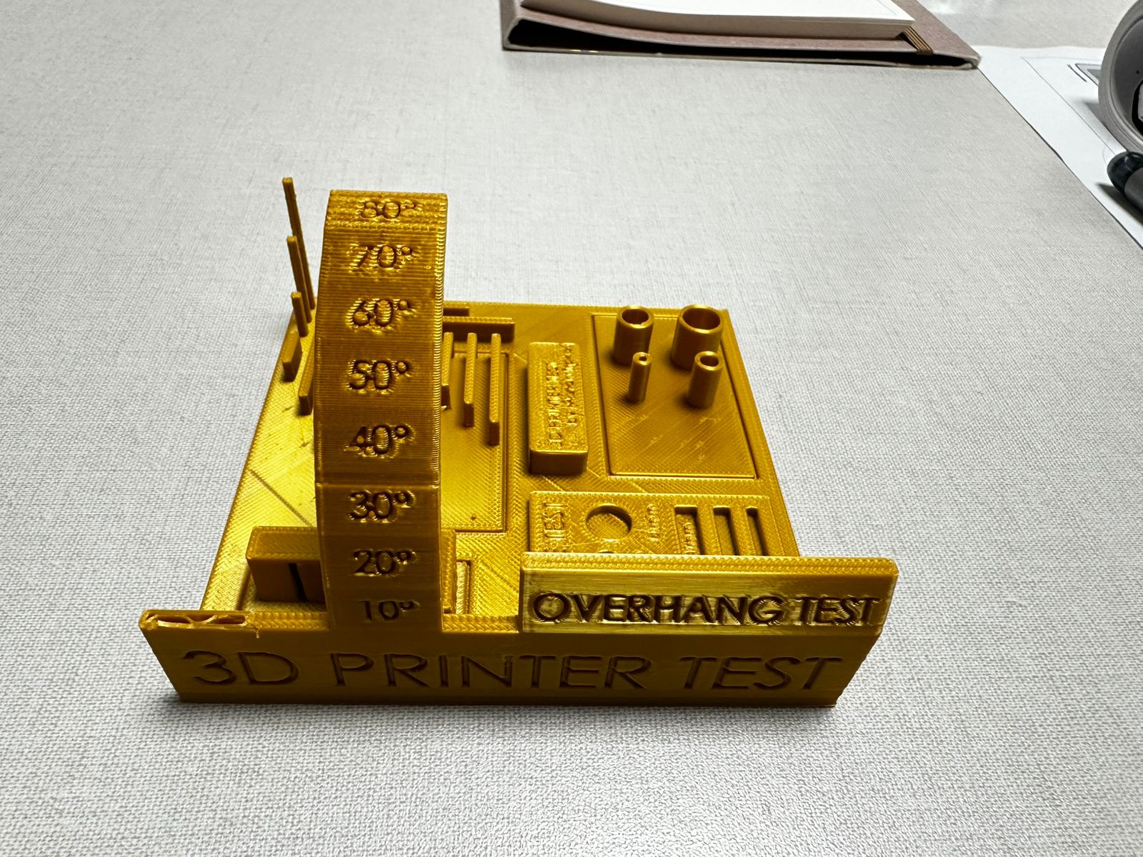
Overall print quality
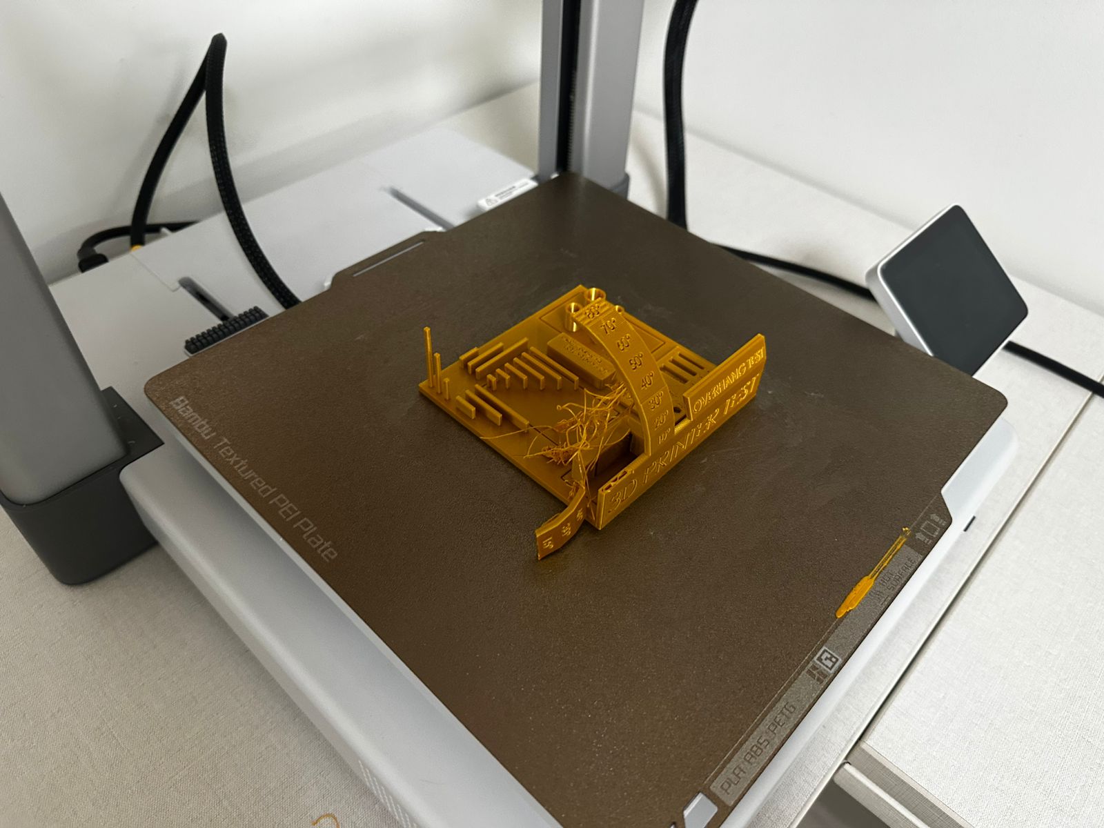
The general print quality is acceptable, and most of the base geometry was printed successfully. The first layers adhered well to the build plate and the main body of the part remained stable during printing. Surface finish is relatively uniform, although visible layer lines can be observed across the model
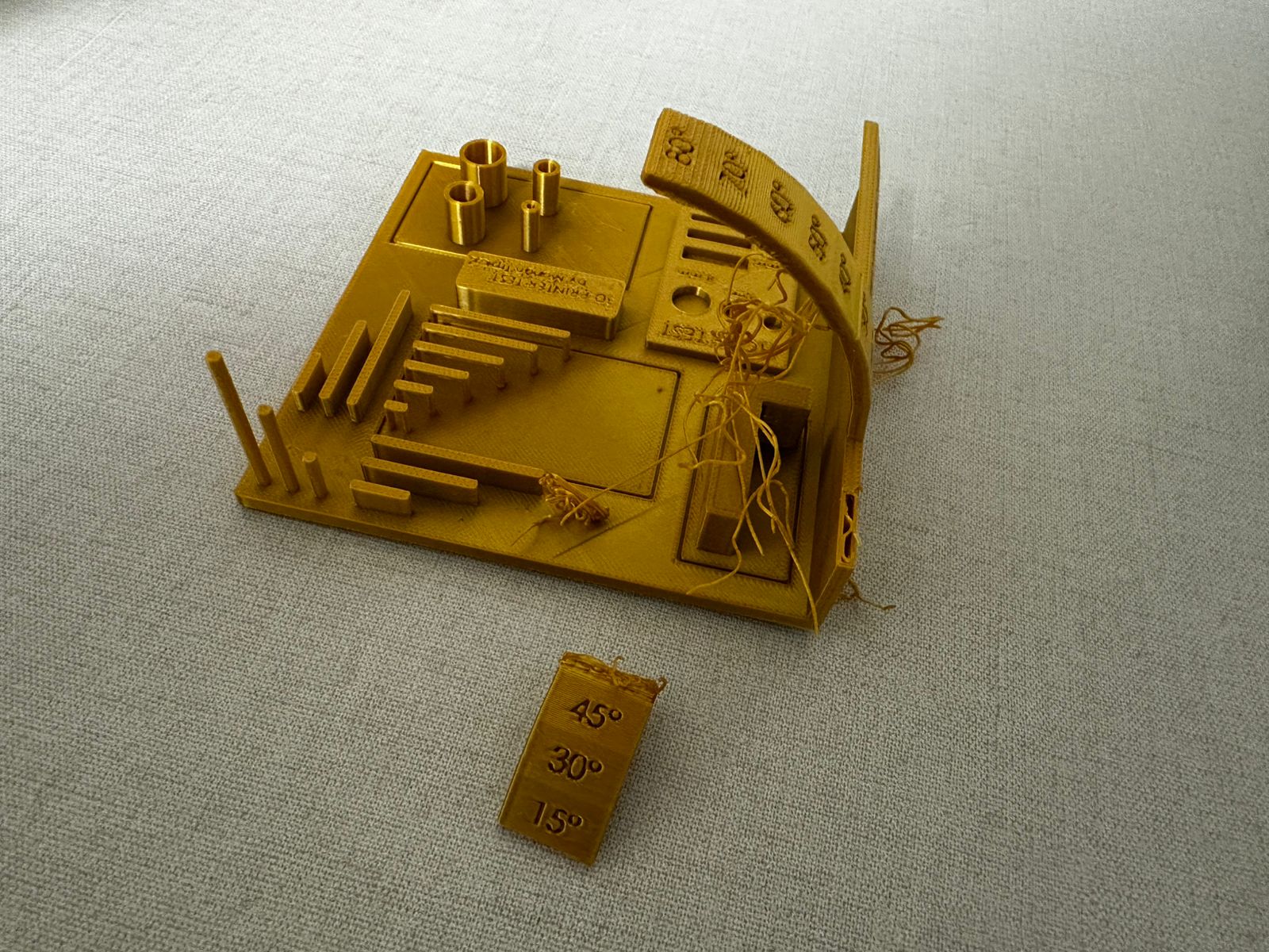
However, the print was not completely successful. One section of the test piece became detached, which indicates that some features were too weak or unstable to be printed reliably under the selected parameters. This affects the interpretation of the test and shows that not all geometries were printed with the same level of stability
Some stringing is also visible, especially around the curved overhang section, suggesting that the retraction settings or travel behavior could still be improved
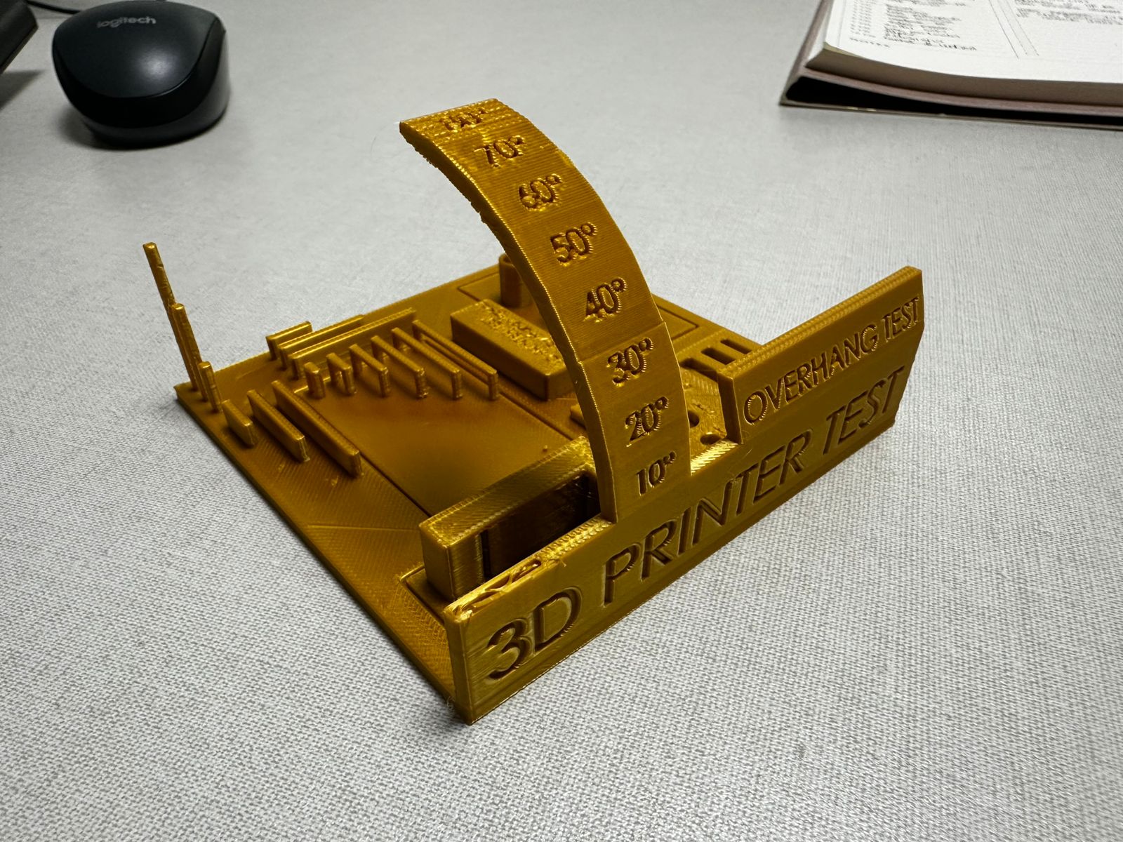
Overhang test
The overhang test ranges from 10° to 80°
From the printed results, the printer handled lower and medium overhang angles reasonably well. Overhangs up to approximately 50°–60° remained mostly stable and preserved their shape
At higher angles, the geometry becomes less reliable. In addition, one of the elements associated with this test detached from the main model, which suggests that the printer had difficulty maintaining stability in unsupported or highly inclined features. This indicates that the machine can manage moderate overhangs, but more extreme angles may require support structures or better tuning of cooling and print speed
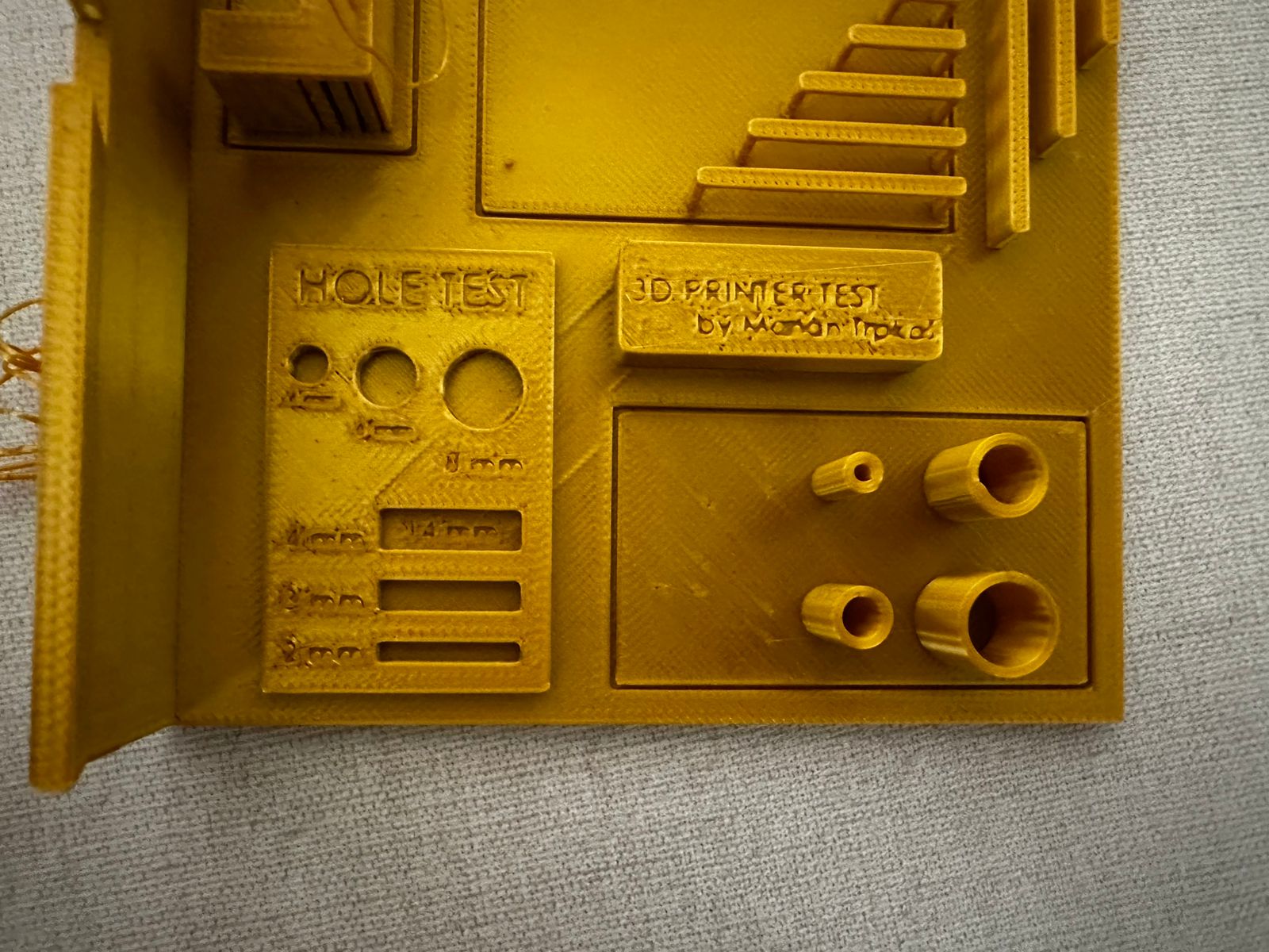
Hole accuracy test
The hole test evaluates dimensional accuracy for circular features
The printed holes appear slightly smaller than their intended dimensions, which is common in FDM printing due to material expansion and extrusion width. Smaller holes are less precise and may require post-processing, while larger holes preserve their geometry more accurately
This suggests that for functional parts requiring precise fits, tolerance compensation should be considered during the design stage
Bridge test
The bridging features show mixed results. Some short spans were printed successfully, but more demanding unsupported features were less stable. Since one part of the model detached, it is clear that the printer struggled when the geometry required sustained printing in areas with limited support
This indicates that bridge performance is acceptable for short distances, but longer spans or more complex suspended geometries would benefit from improved cooling or adjusted print settings
Fine detail and small features
The model includes several fine details such as thin vertical pins, small geometric features, and embossed text labels. While most of the vertical pins printed successfully, the smallest text elements did not reproduce clearly
Some of the engraved and embossed labels (such as the hole and print test markings) appear blurred or partially filled, making them difficult to read. This indicates that the printer has limitations when reproducing very small text features with the current nozzle size and printing parameters
This behavior is common in FDM printing, where very small details may lose definition due to extrusion width and layer height. To improve text readability, larger font sizes, deeper engravings, or a smaller nozzle could be used
Conclusion
The calibration print shows that the printer is capable of producing stable results in many areas of the model, especially in the base, vertical features, and medium-difficulty geometries. However, the test also revealed important limitations. One part of the model detached, indicating that highly unsupported or weak features were not fully reliable under the selected settings
Overall, the printer performs well for standard geometries, moderate overhangs, and basic dimensional tests, but more challenging features would require better tuning of retraction, cooling, speed, and possibly the use of supports
Additional 3D printing tests observed
During the group work session we also analyzed several reference tests available in the PUCP digital fabrication laboratory. These demonstrations help visualize how different printing parameters affect the internal structure and mechanical behavior of 3D printed parts
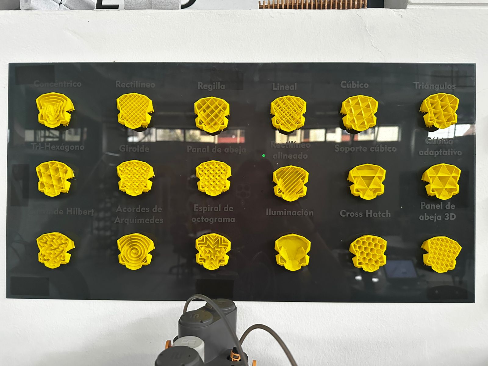
Infill pattern comparison
One of the demonstrations showed a comparison between different infill patterns used in FDM 3D printing. Infill structures determine how the internal volume of a printed object is filled and directly influence strength, weight, material consumption, and printing time
Among the patterns displayed were concentric, grid, linear, cubic, triangular, gyroid, honeycomb, and cross-hatch structures. Each of these geometries distributes internal forces differently and may be selected depending on the functional requirements of the printed part.
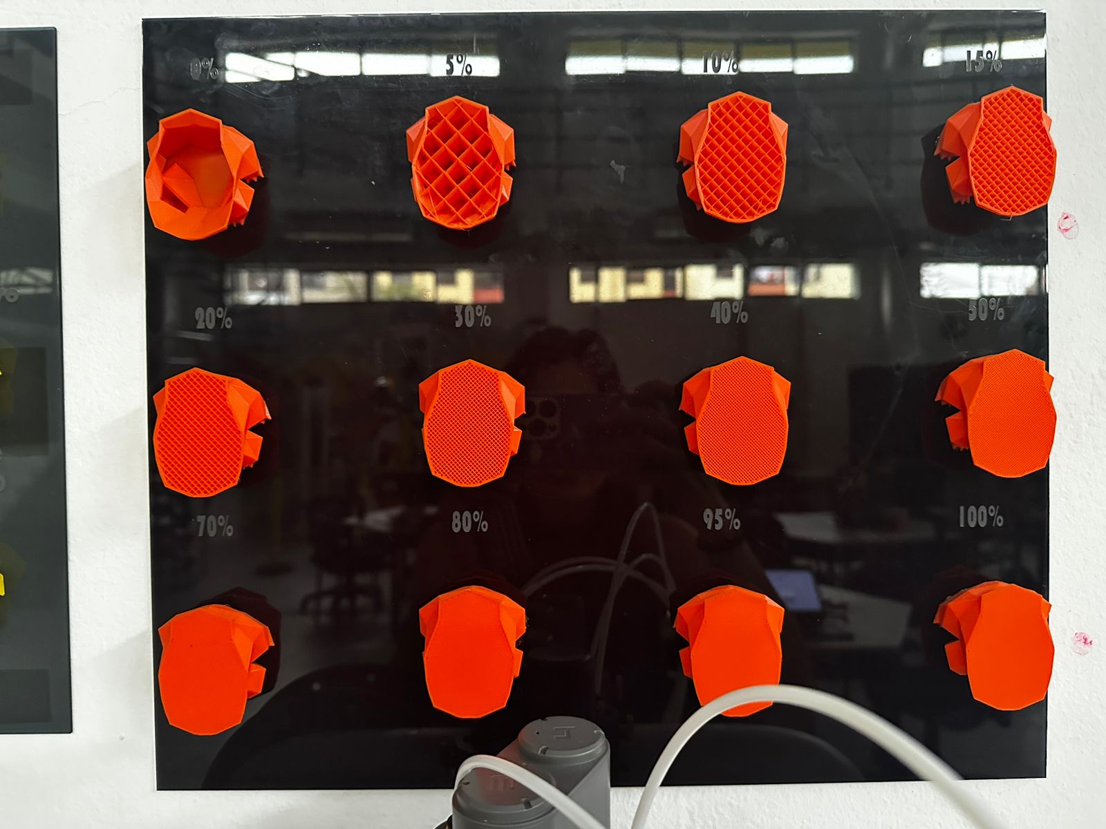
Infill density comparison
Another reference board demonstrated how infill density affects the internal structure of a printed object. Samples were printed with densities ranging from 0% to 100%
Lower densities produce lighter parts with reduced material usage and faster printing times, while higher densities increase strength and rigidity but also increase material consumption and printing duration.
Wall thickness test
A third test compared different wall thickness configurations. Wall thickness plays an important role in the structural stability of the printed object. Increasing the number of walls improves strength and durability, while thinner walls reduce material usage and print time
These visual demonstrations help better understand how slicing parameters influence the internal geometry and mechanical performance of 3D printed parts.
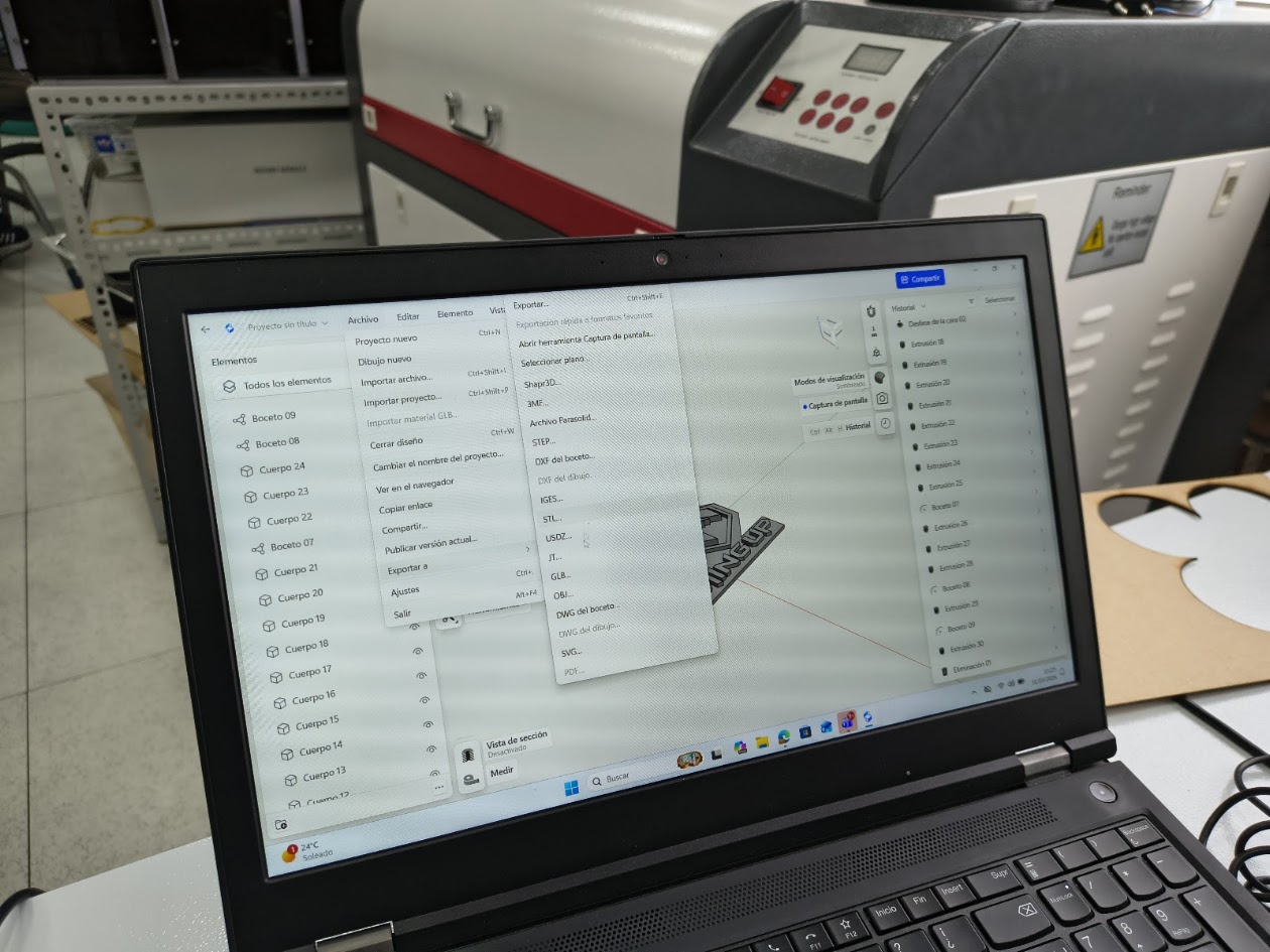
Download files
The design files used in this assignment can be downloaded below.
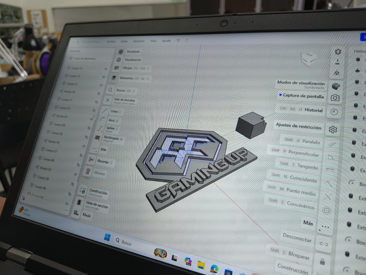
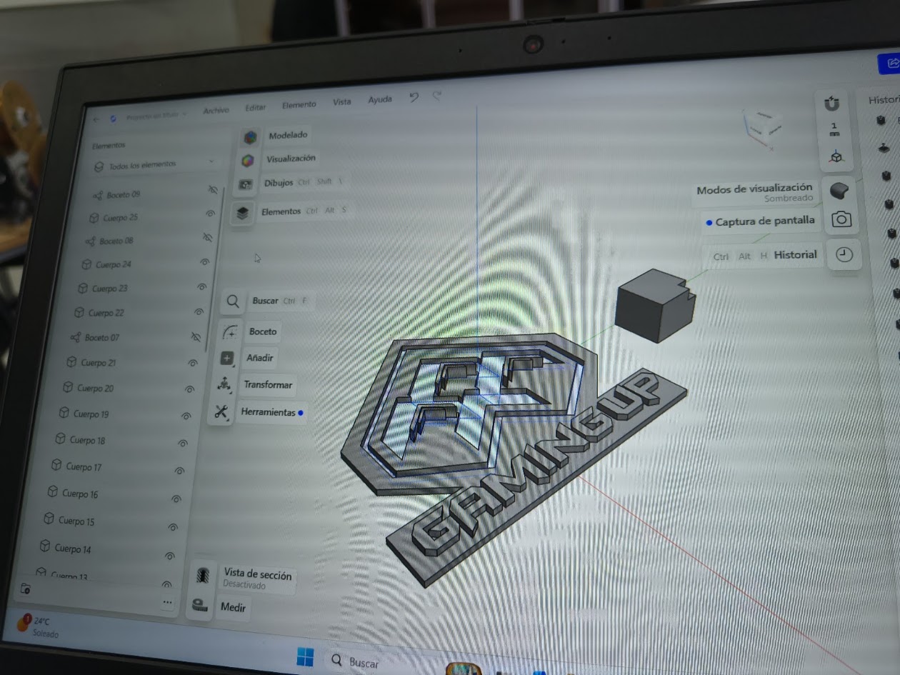
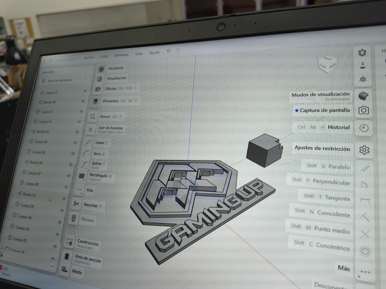
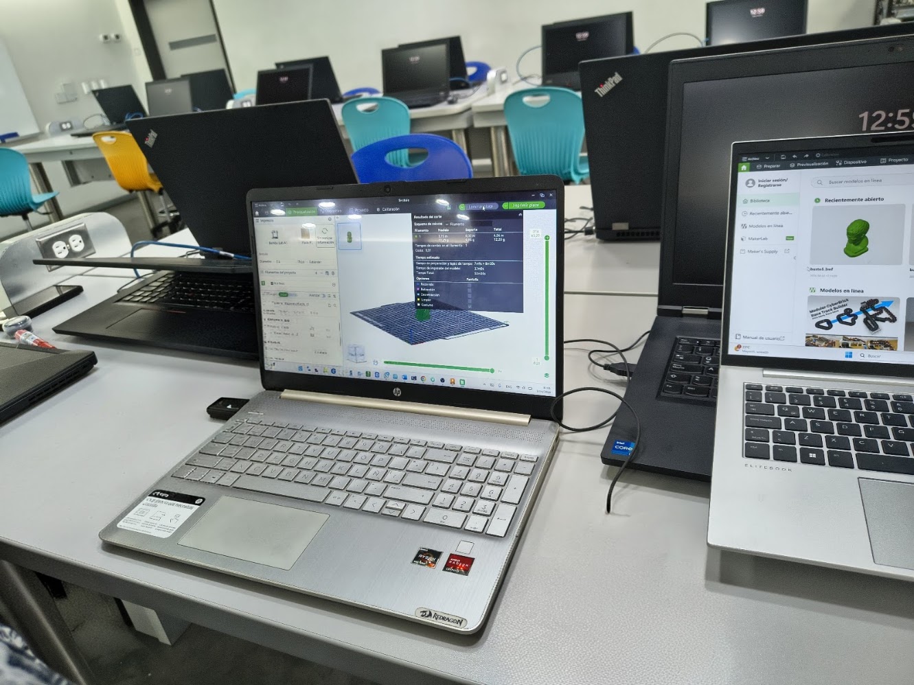
4) Individual assigment - 1. 3D Printer
Problems
How to design a 3D piece
How to use the 3D printer and phases
Solutions
Learn how to use the devices
Ask for help
Review tutorials


Video demonstration
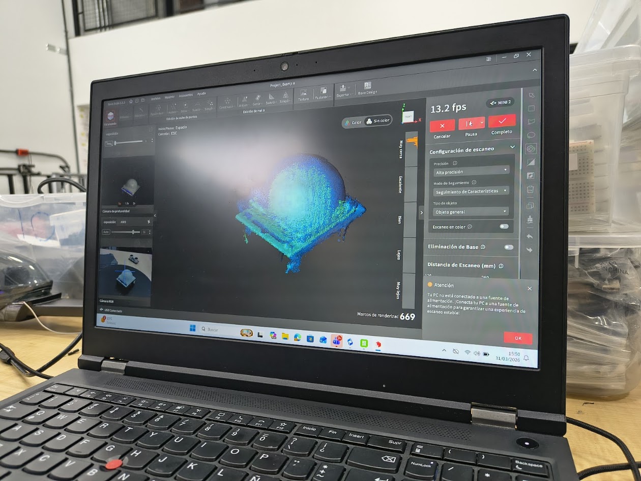
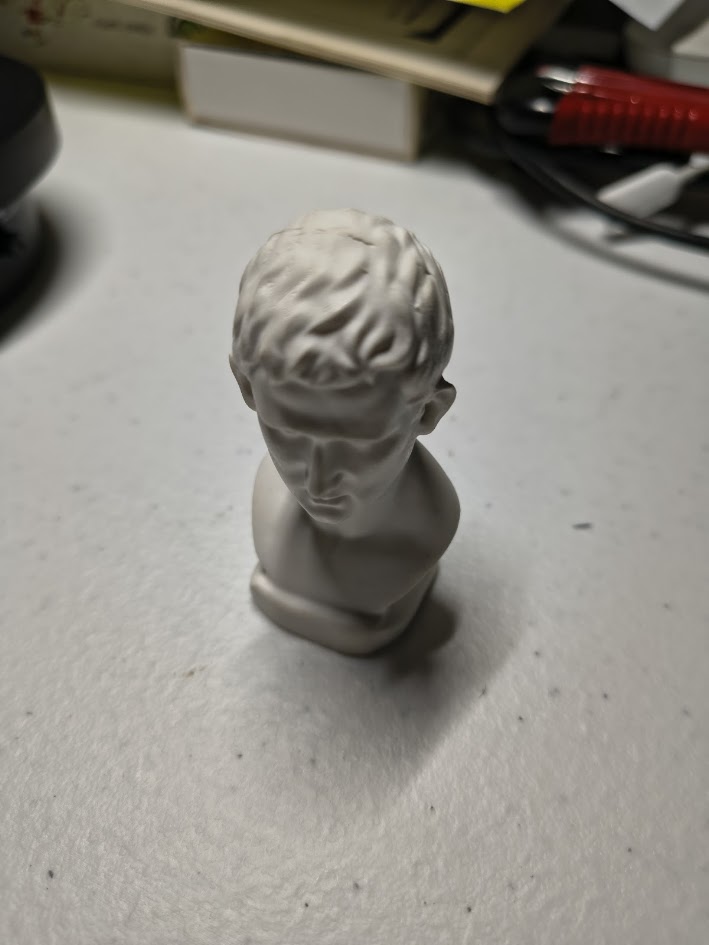
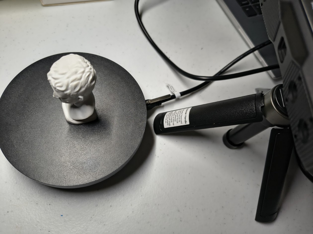
4) Individual assigment - 2. Scanner
Problems
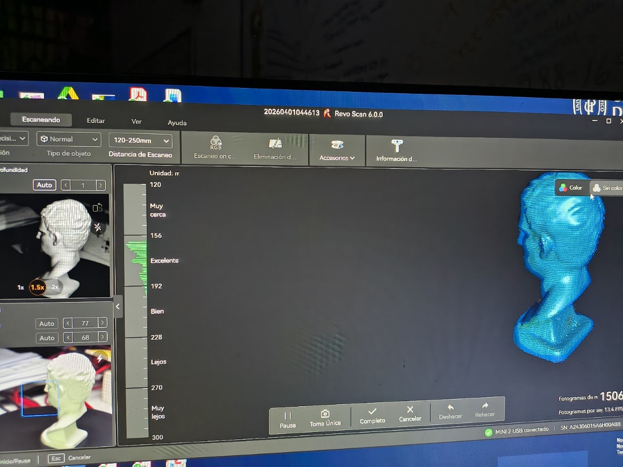
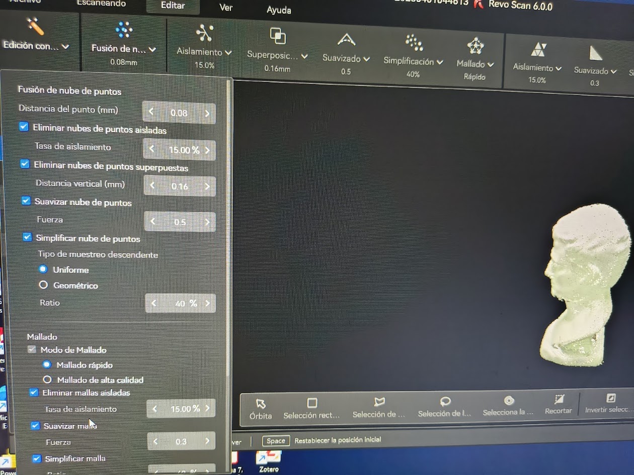
How to use the scanner
Adjusting the scanner settings: distance, light, movement, other
Solutions
Interact, interact and interact with the scanner
Step by step: ask for help
Review tutorials
Video demonstration
5) Final results
- Linked to the group assignment page
- Explained what you learned from testing the 3D printers
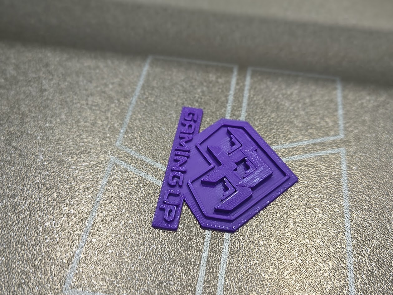
- Documented your design and 3D printed your object and explained why it could not be easy made subtractively
- Documented how you scanned an object
- Include your original design files for 3D printing
- Included a 'hero shot' of your board
6) References files
We learn how to design, make and test a 3D printer and Scanner