Assignment requirements
Group assignment
- Do your lab's safety training
- Characterize your lasercutter's focus, power, speed, rate, kerf, joint clearance and types
- Document your work to the group work page and reflect on your individual page what you learned
Individual assignment
- Design, lasercut, and document a parametric construction kit, accounting for the lasercutter kerf
- Cut something on the vinyl cutter
Progress Status
Test equipment
Use EDA tool
Upload source files
1) Introduction
My main goal: learn EDA tools, parametric construction, and domain the technology of laser and vinil cutting
2) Equipments and materials
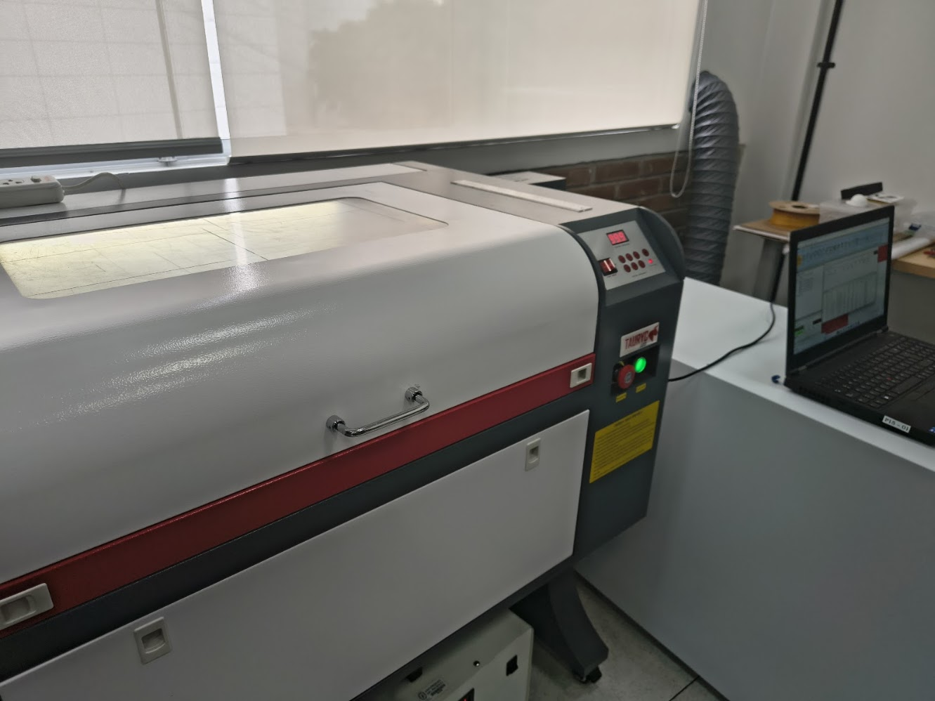
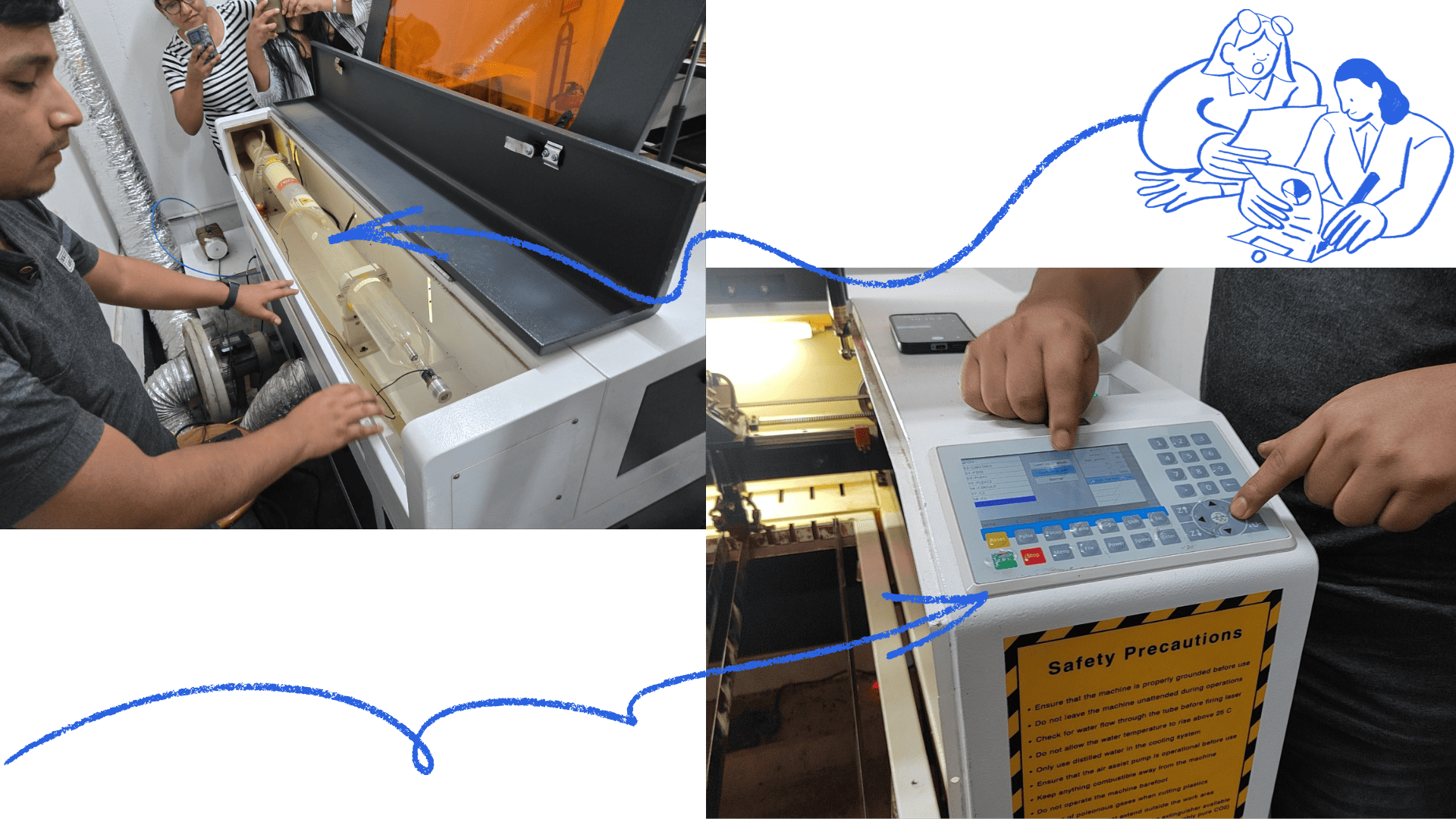
Tauryc Laser Machine
- Emergency stop (red button)
- Power / Laser (green button)
- Control panel
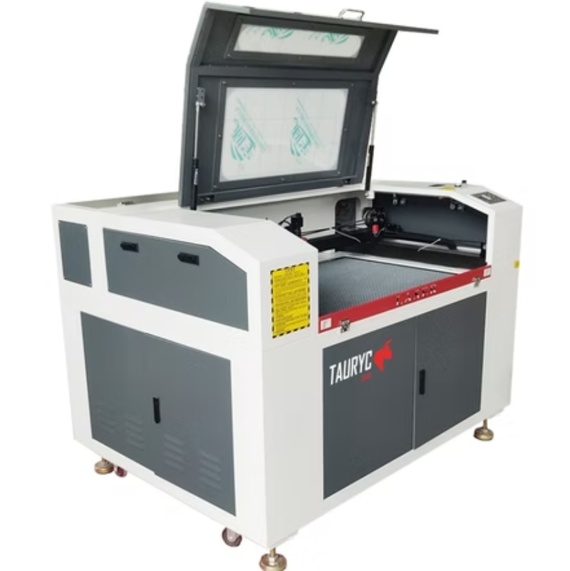
Tauryc 9600 Laser Machine
- Controller: RUIDA 6445G
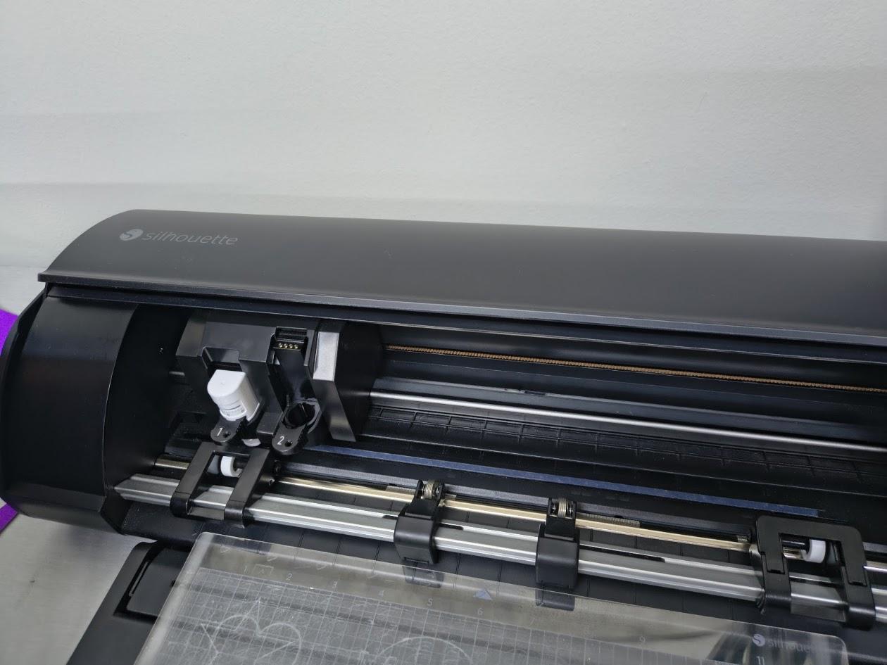
Silhouette Cameo 5
- Maximum Cutting Length: 16 ft (487.7 cm)
- Maximum Material Thickness: 3 mm (118.11 mils)
- Maximum Cutting Speed: 1–10 mm/s (1 mm/s step), 10–300 mm/s (10 mm/s step)
- Mechanical Resolution: 0.00625 mm
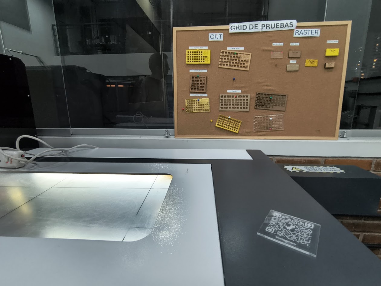
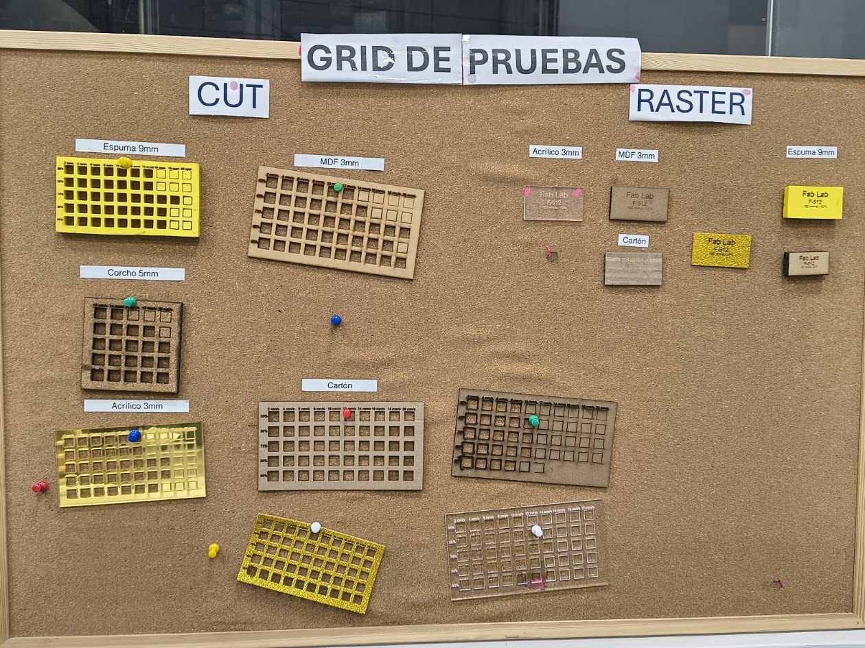
3) Group assignment results
For more details visit Fab Lab Peru Week 3 Group assignment
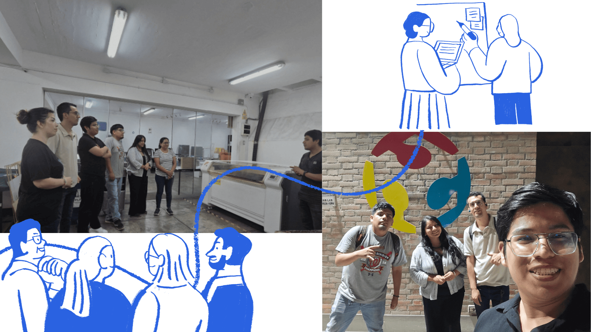
We are part of the Fab Academy network of nodes. It was developed between 2010 and 2011 and officially inaugurated during the FAB7 World Congress. Fab Lab Peru is a node with presence in various regions: Lima, Junín, and Loreto. For this group assignment, we meet to coordinate ideas, objectives, and responsibilities.
The meeting allowed us to explore and evaluate different materials and their applications for digital fabrication. During this session, we worked on the group assignment.
We were guided by Evelyn Cuadrado as instructor and Grace Schwan as academic support.
Laboratory safety training
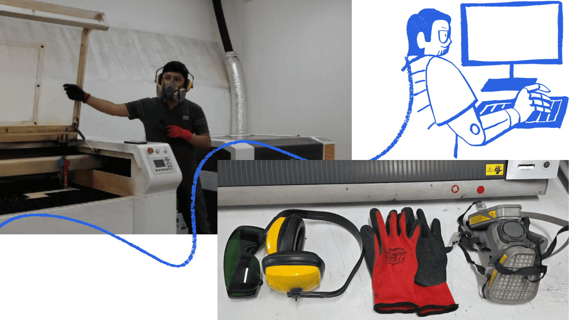
🦺 Safety training
We received safety training by instructor Jheferson Lados Villegas. He explained the importance of personal safety and the correct use of protective equipment such as glasses, gloves, masks, and ear protection. These elements are essential to prevent accidents and protect against risks like laser radiation, noise, and particle emissions.
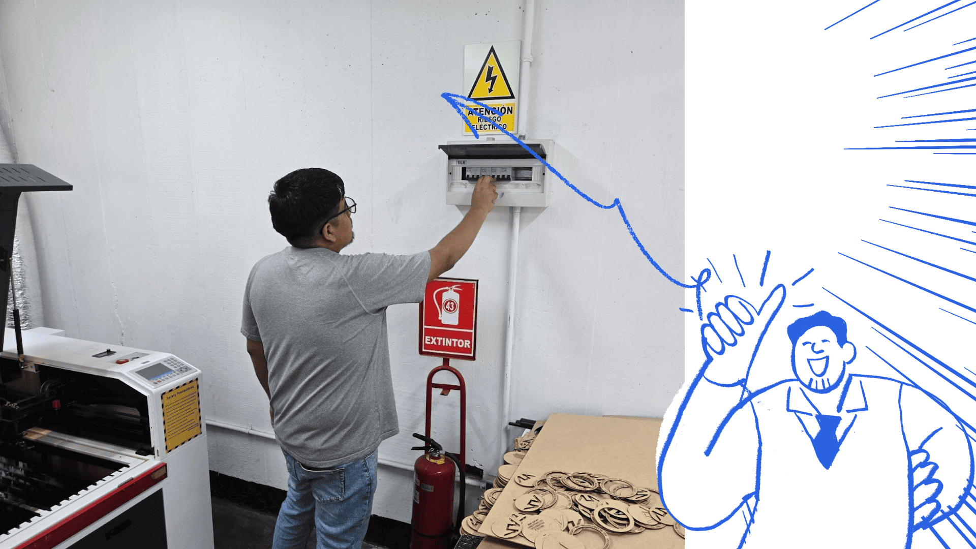
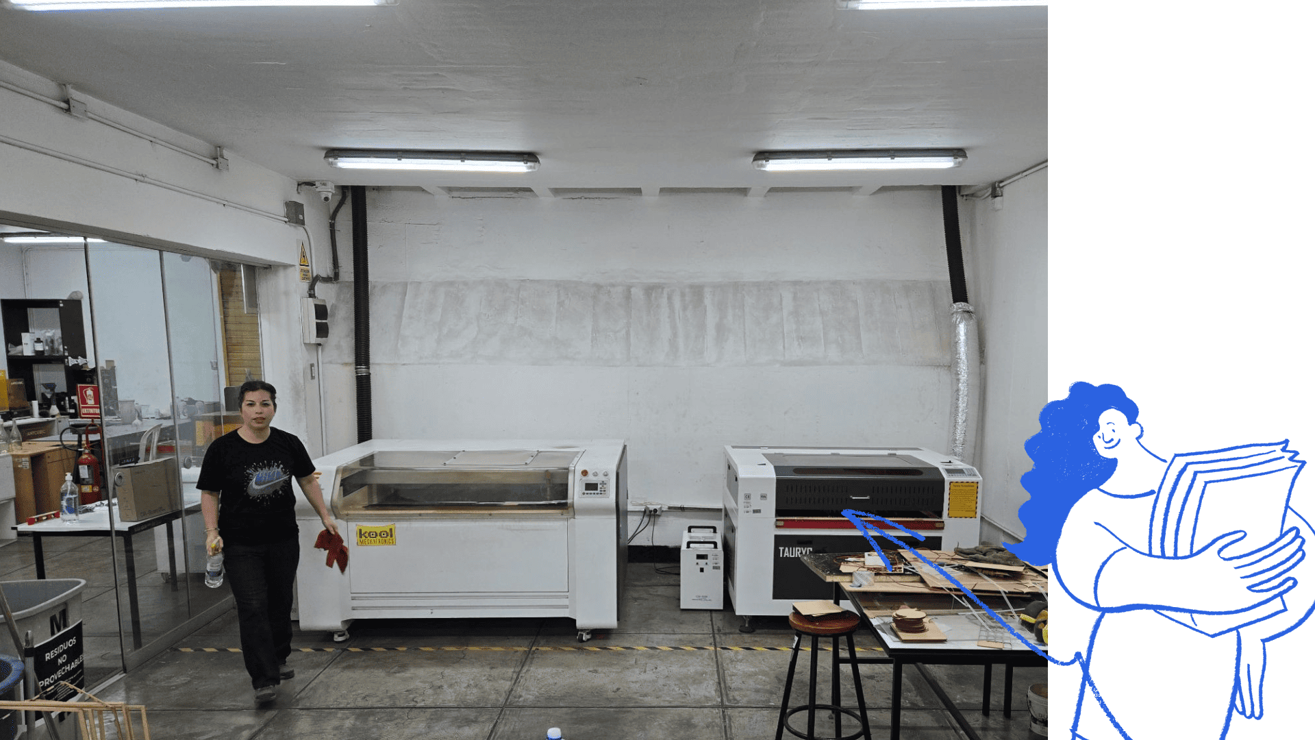
⚡ Laboratory tour
We want to identify safety signage and electrical panels, main panel and individual panels for each laser machine. Rules emhasize to ensure safety operations
🛠️ Laser machines
Laser machines were introduced, explaining their uses and power levels depending on the material. Some machines operate with a closed hood, while others require extra caution and protective eyewear.
⚙️ Machine components
The main parts: laser tube, mirrors, lenses, cutting head, worktable, fume extraction system, control panel, and power supply. Each component ensures precision and efficiency.
✅ Best practices
Key recommendations include checking materials before cutting, adjusting power and speed correctly, never leaving the machine unattended, keeping the workspace clean, and following instructor guidance to ensure safe and efficient operation.

Calibration tests
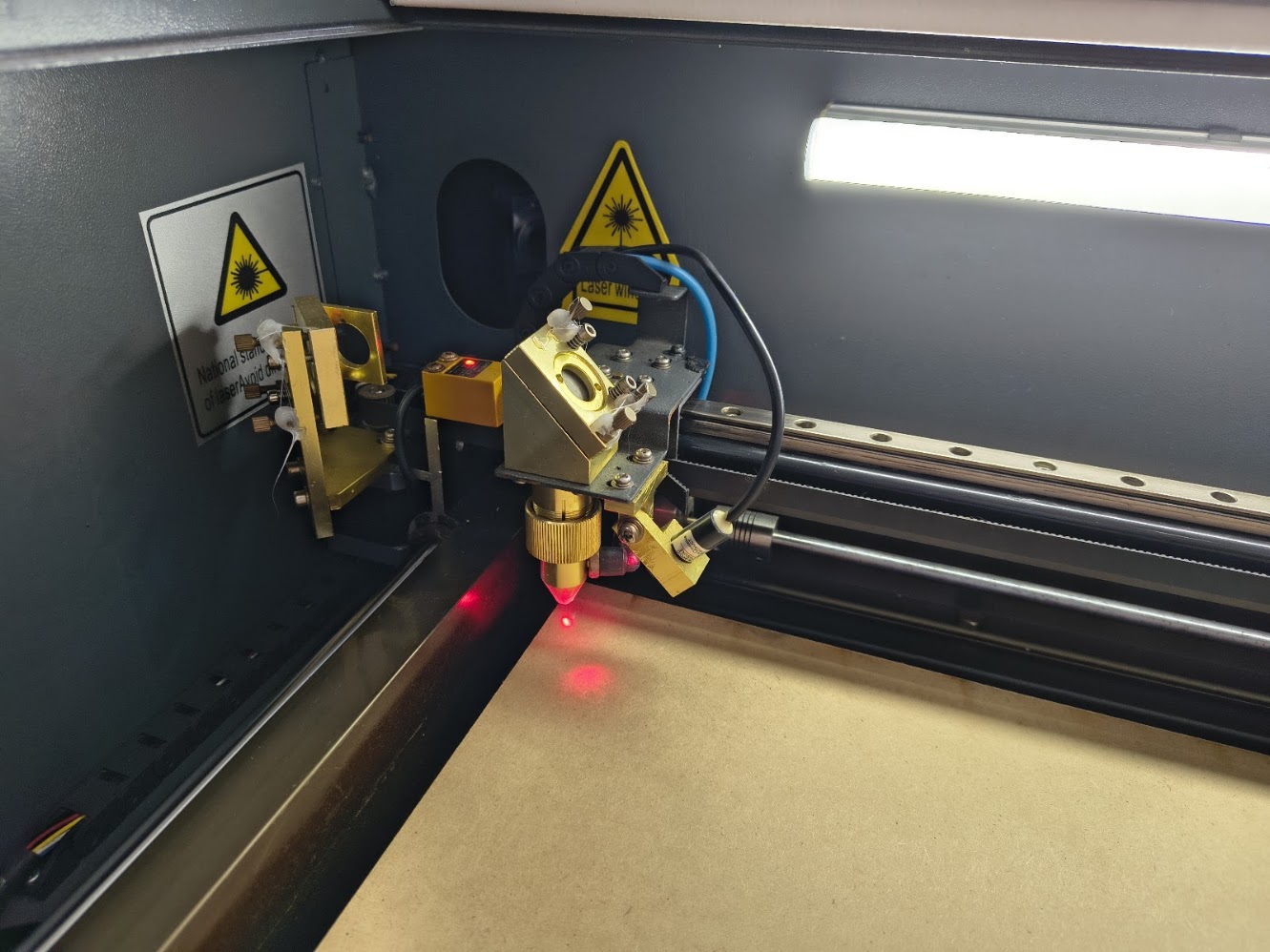
🎯 Machine calibration
Calibrating a laser cutting machine is essential to ensure accuracy, quality, and safety. The first step is leveling the worktable and adjusting the height to achieve optimal laser focus on the material.
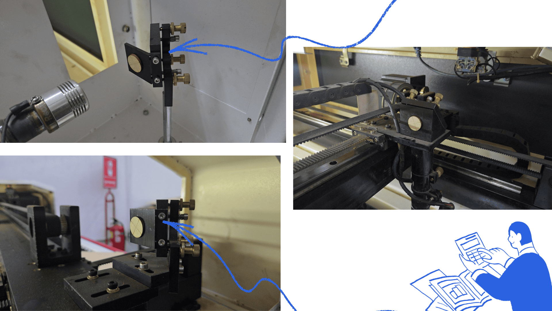
🔍 Mirror alignment
The mirrors must be clean and properly aligned, as misalignment affects the laser beam path. A laser pointer or marker is used to verify that the beam reflects correctly from each mirror to the cutting head.
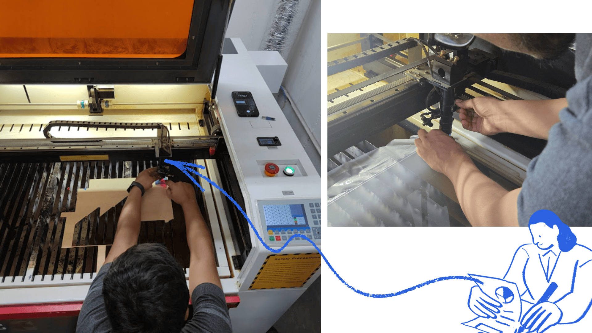
📐 Cutting head alignment
The cutting head must be aligned perpendicular to the work surface. Any deviation can result in irregular cuts or reduced precision, so careful adjustment is required.
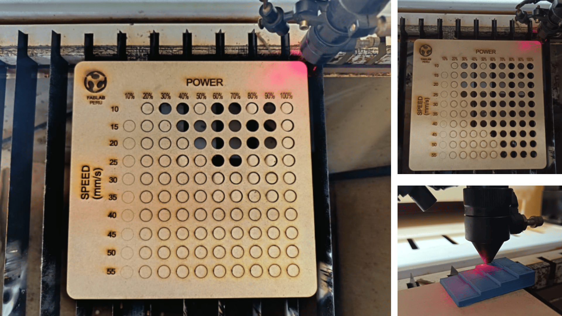
Parameter – MDF 2.6 Tests
🖥️ Template Preparation
We edited our laser cutting and engraving test template using Corel Draw, optimizing it and adding our letterhead. The template includes cutting, marking, and engraving operations in both vector and bitmap formats.
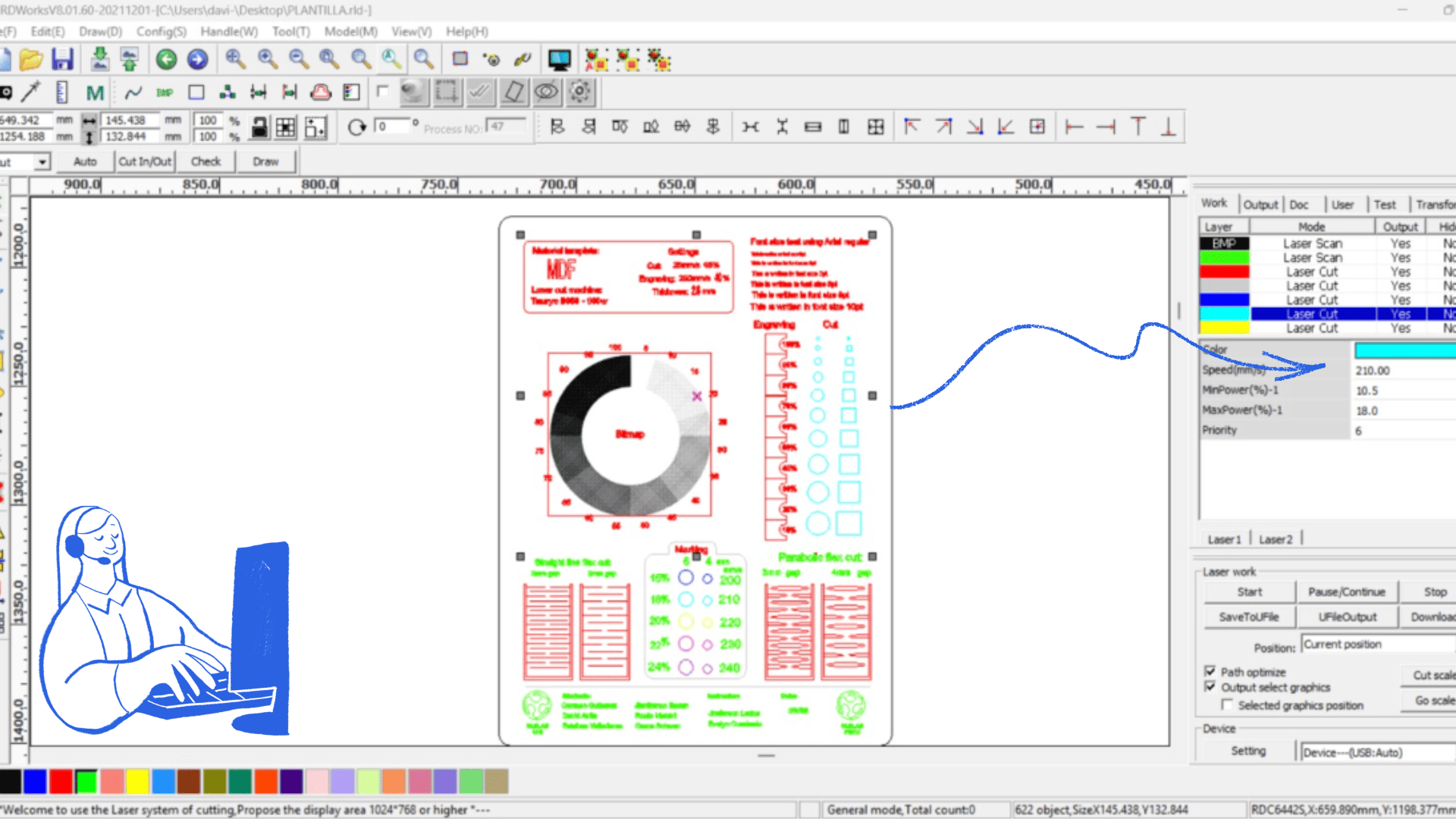
⚙️ RDWorks Setup
The template was exported to the RDWorks laser controller software. We adjusted the grayscale palette in bitmap mode to properly test engraving performance.
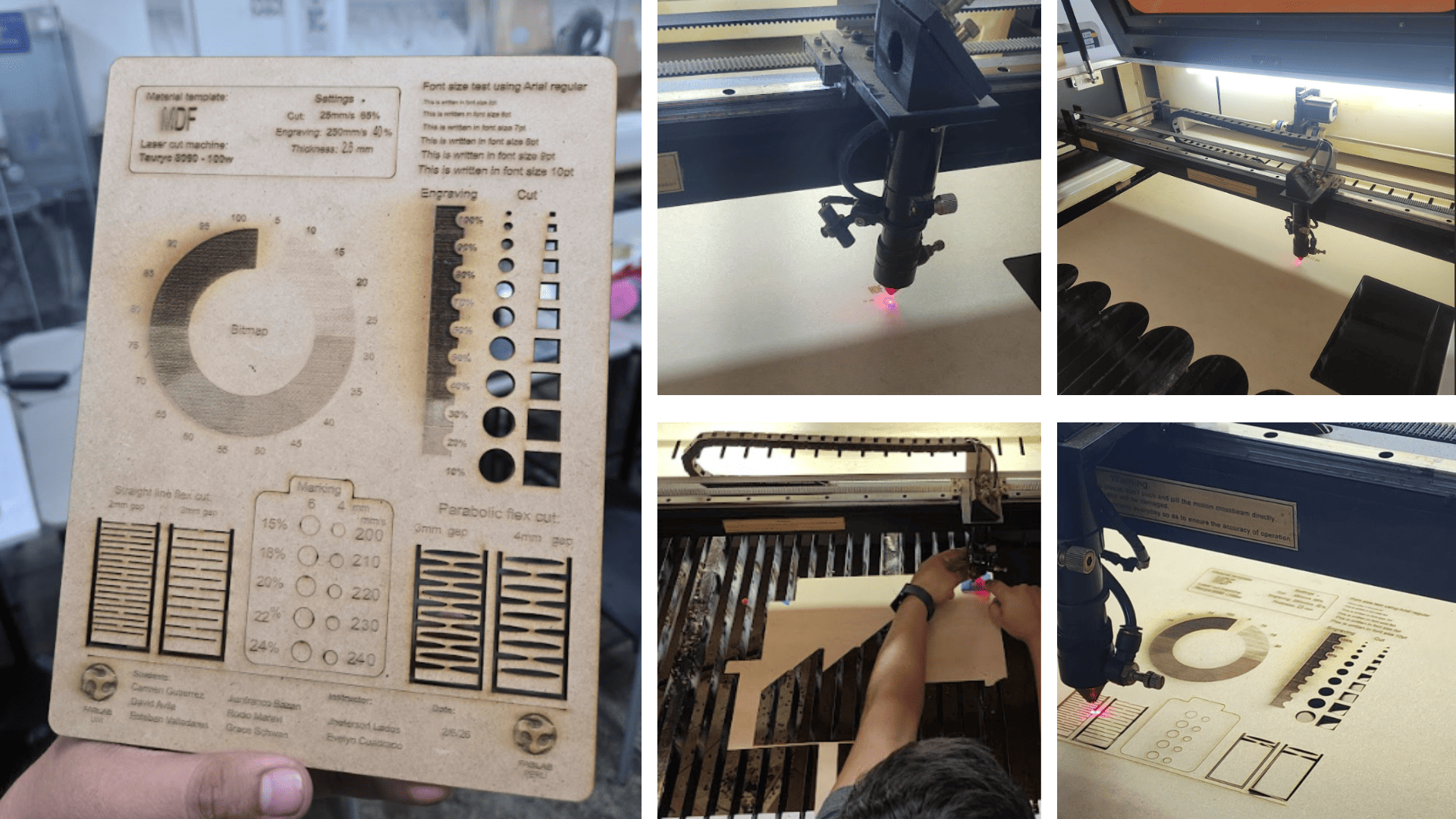
📊 Test results & observations
- The bitmap engraving required a dot grid configuration to correctly display grayscale.
- The engraving power tower did not appear stepped due to the burnt finish of the material.
- Minimum cut sizes were accurately represented in basic shapes.
- Text readability was consistent across different letter sizes.
- Laser marking tests produced clean and optimal results.
- Flexible pattern tests in 3 mm spacing showed increased material flexibility.
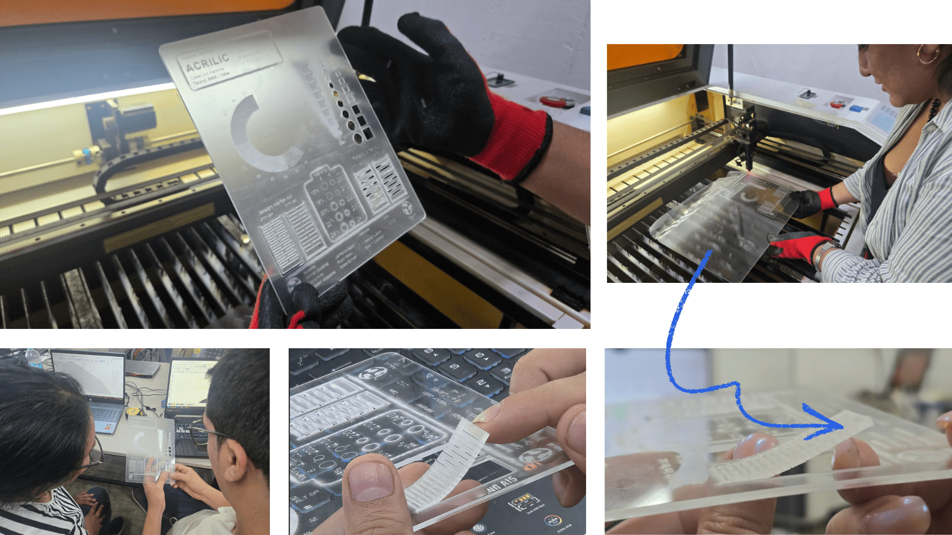
Parameters – Acrylic 2mm
✨ Cutting & Engraving Test
A laser cutting and engraving test was performed on acrylic. Different power and speed parameters were evaluated to achieve a clean and precise finish. The cut produced polished edges typical of CO₂ laser processing, while engraving resulted in a uniform matte surface.
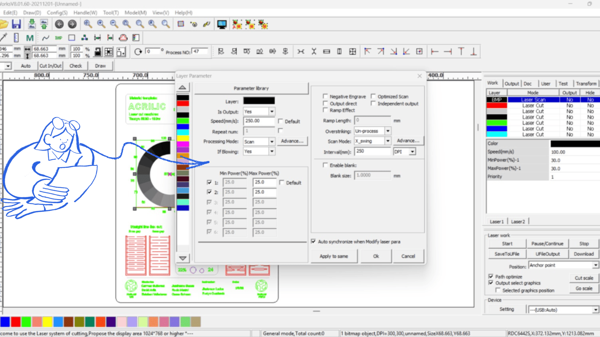
📊 Observations
- Bitmap engraving required a dot grid configuration for grayscale.
- The engraving power tower did not appear stepped due to material finish.
- Minimum cut sizes performed well in basic shapes.
- Text readability was consistent across sizes.
- Laser marking produced clean and defined results.
- Flexible pattern tests showed good material flexibility at 3 mm spacing.
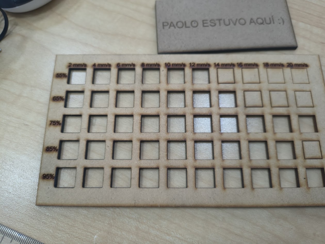
Minimum & Maximum speed and power test
⚡ Parameter evaluation
Tests were conducted using extreme values of speed and power to identify optimal laser settings. At minimum values, cuts were incomplete and engraving was faint. At maximum values, cutting was faster but increased the risk of burning or melting edges. These results helped define a safe and effective parameter range depending on the material and thickness.
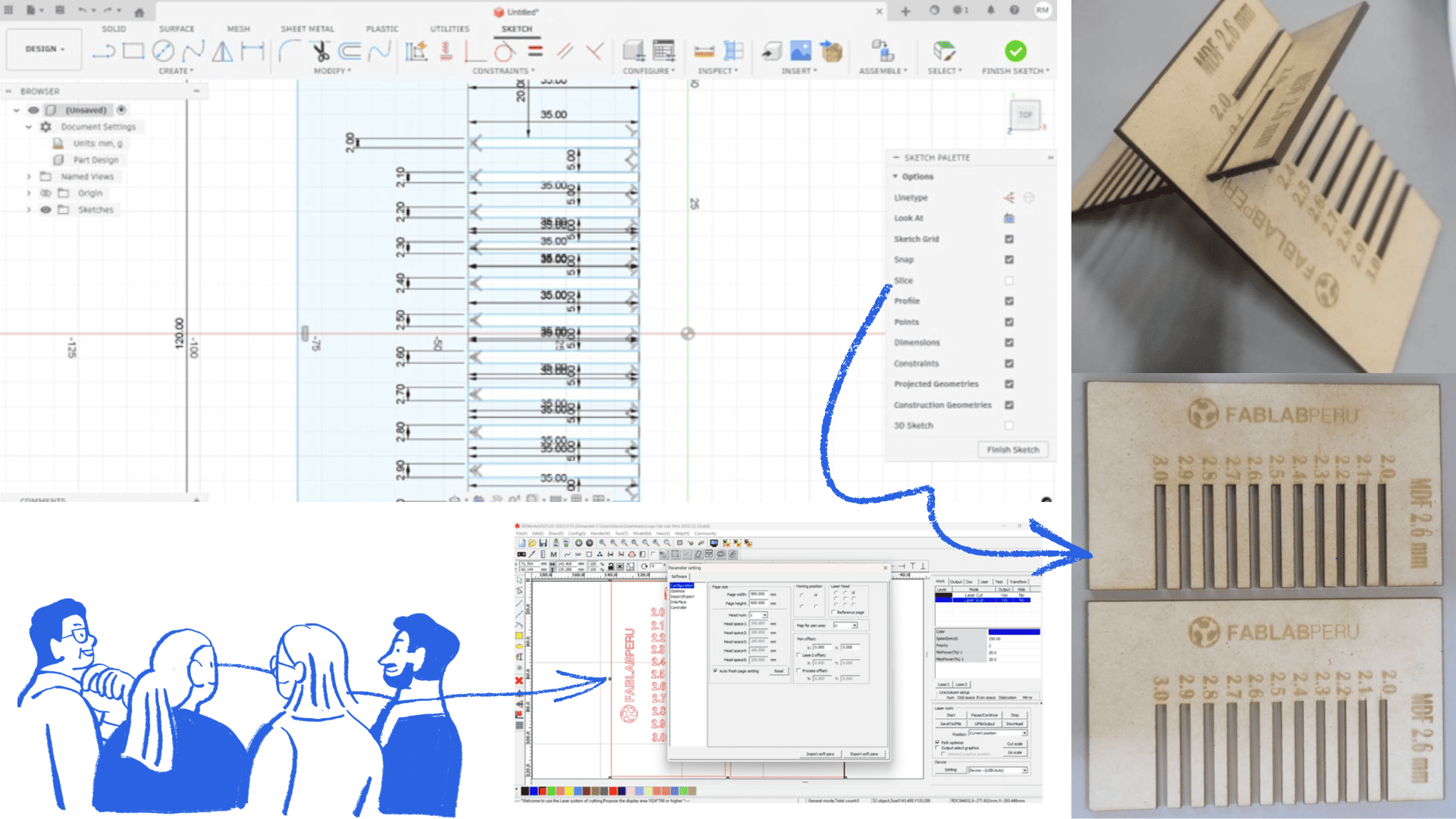
Kerf test
📏 Measurement & Fit
A kerf test was performed to measure the material removed by the laser during cutting. A sample with multiple grooves of varying sizes was designed to evaluate the fit between male and female parts. The results allowed us to calculate material loss and adjust digital designs for precise assembly.
Responsible use
🏫 Workspace responsibility
Fab Lab UNI provided a well-equipped and safe environment for our group work.
This space enabled hands-on learning and collaboration using various tools and machines.
Respect for shared spaces was emphasized. After completing our work, we ensured the laboratory
remained clean and organized, following established rules. Maintaining the workspace ensures safety,
proper equipment function, and availability for future users.
4) Individual assignment 1 - Laser machine
Problems
- Software did'nt work
- Incorrect speed and laser power intensity
Solution with laser machine
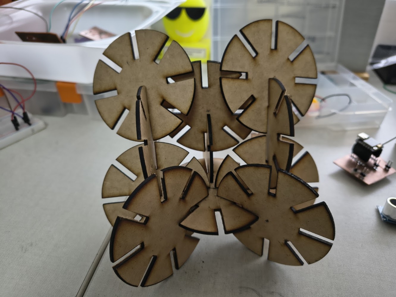
- Parametric design
- Setup up laser power intensity
- Control speed
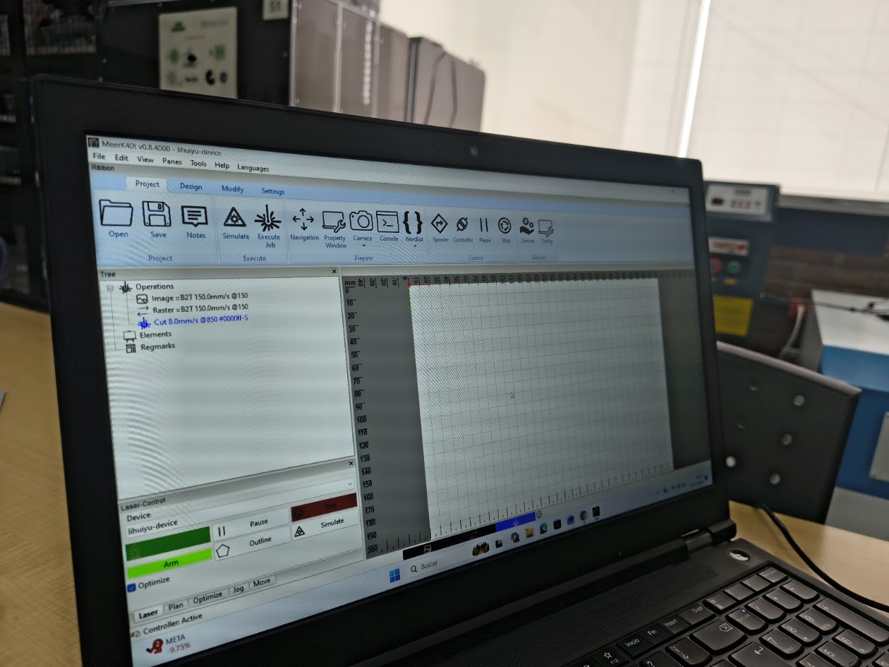
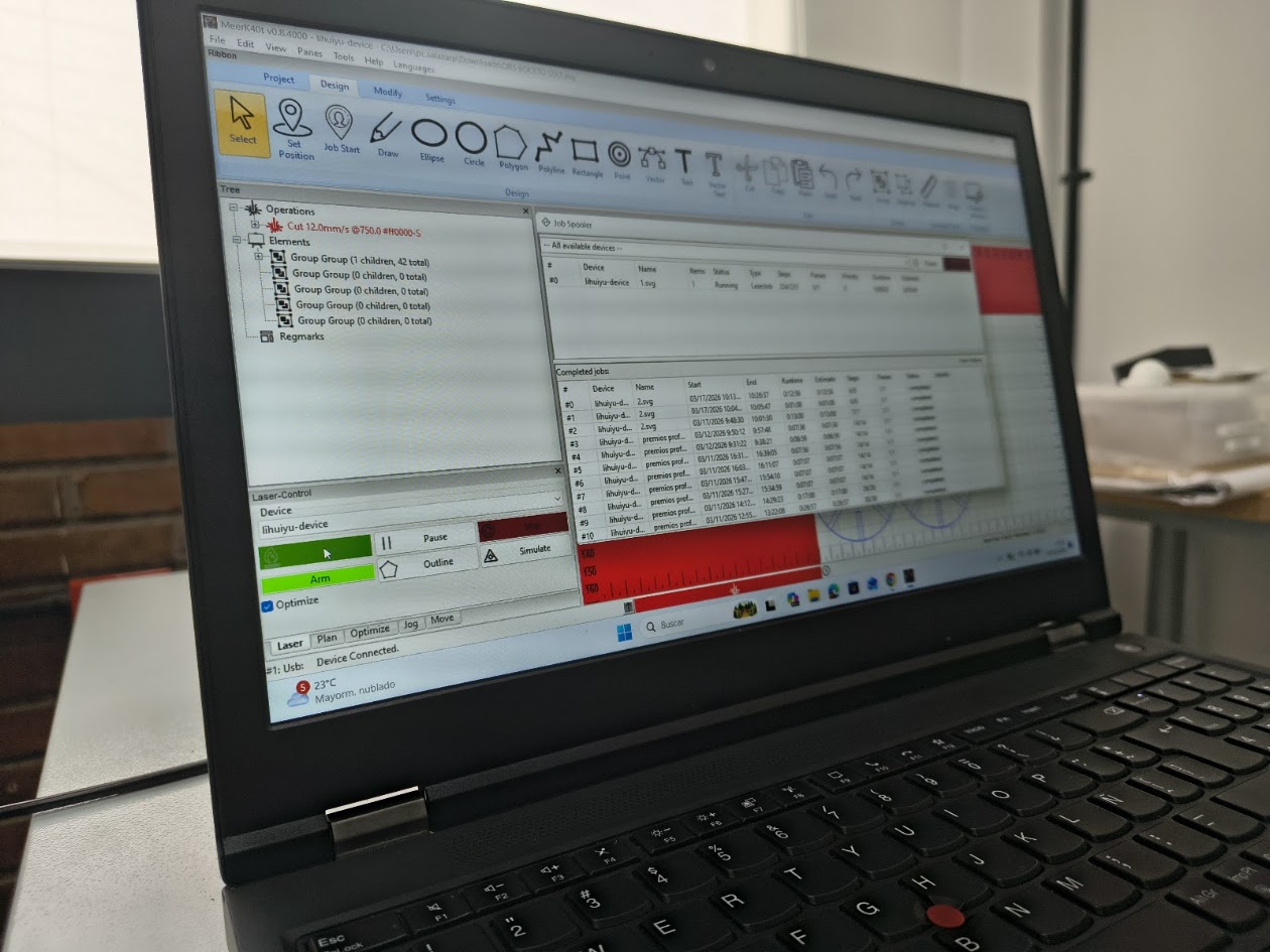
Open a parametric project with Meerk40t software - https://github.com/meerk40t/meerk40t MeerK40t (pronounced MeerKat) is a built-from-the-ground-up MIT licensed open-source laser cutting software.
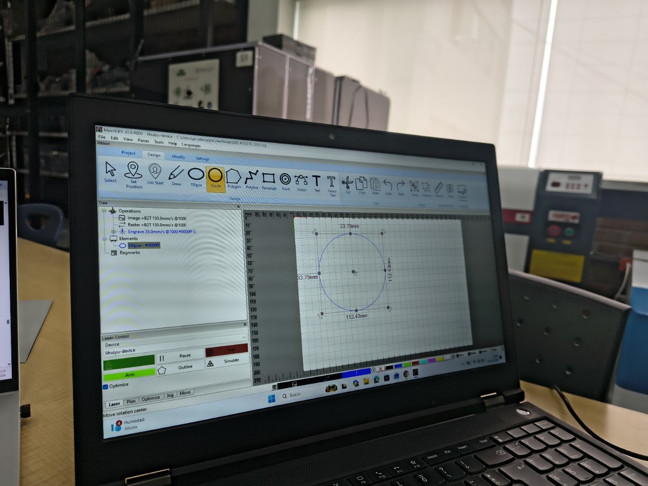
Designing the first piece - The primary goals of this software is simple: 1) Provide users a quality laser control software 2) Provide developers a platform to help further their own ideas, and provide novel work.
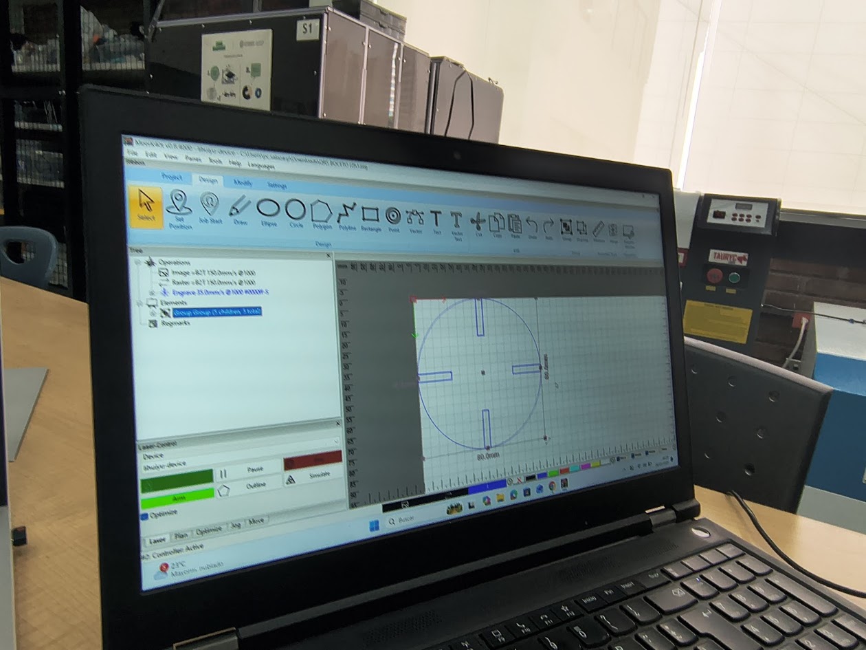
Adding 4 lots in the circle
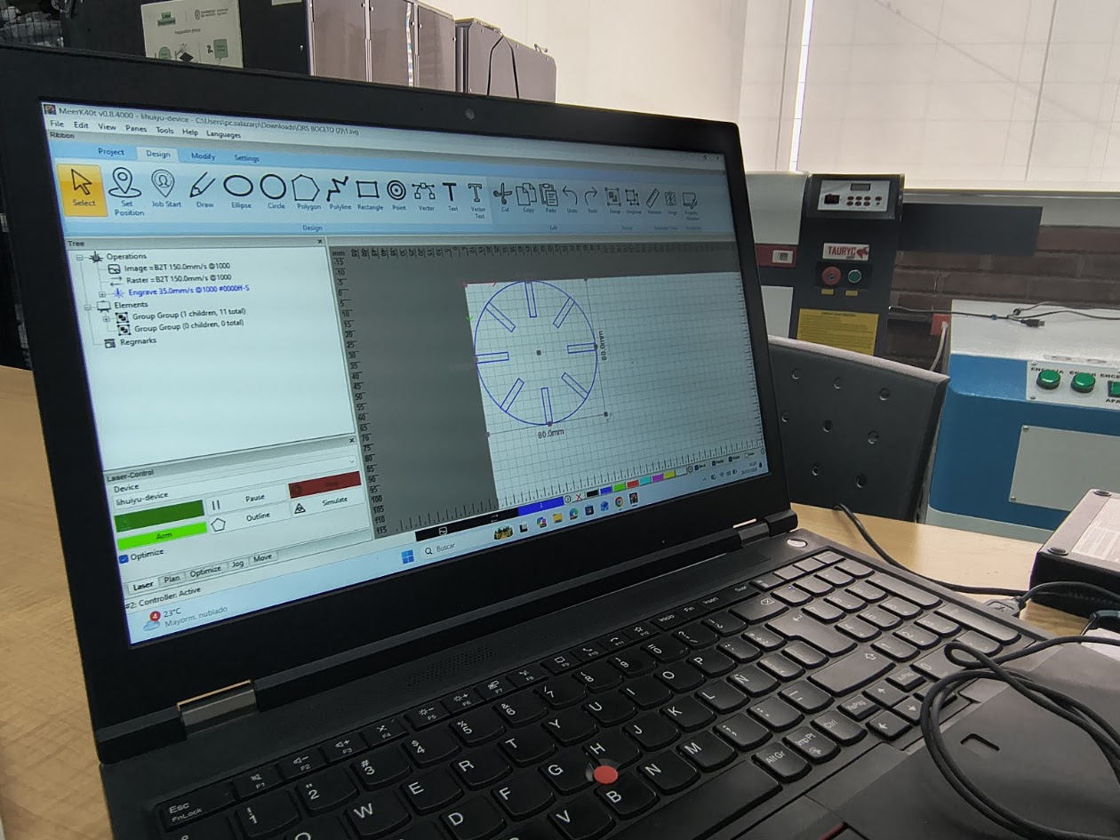
Adding 4 lots in the circle at 45°
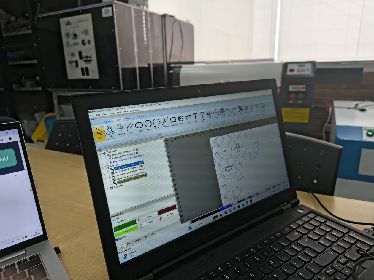
Copy three times
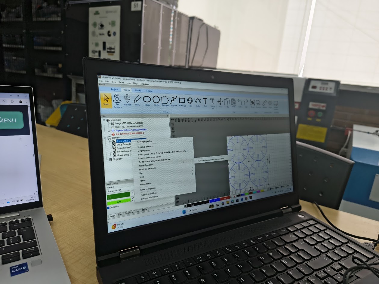
Review the laser cutting speed and power
Review the laser cutting materials, speed and power
Review the laser cutting materials, speed and power
Review the laser cutting speed and power. Depending on the material, the speed and power will be different type of cut.
We used a 2mm MDF
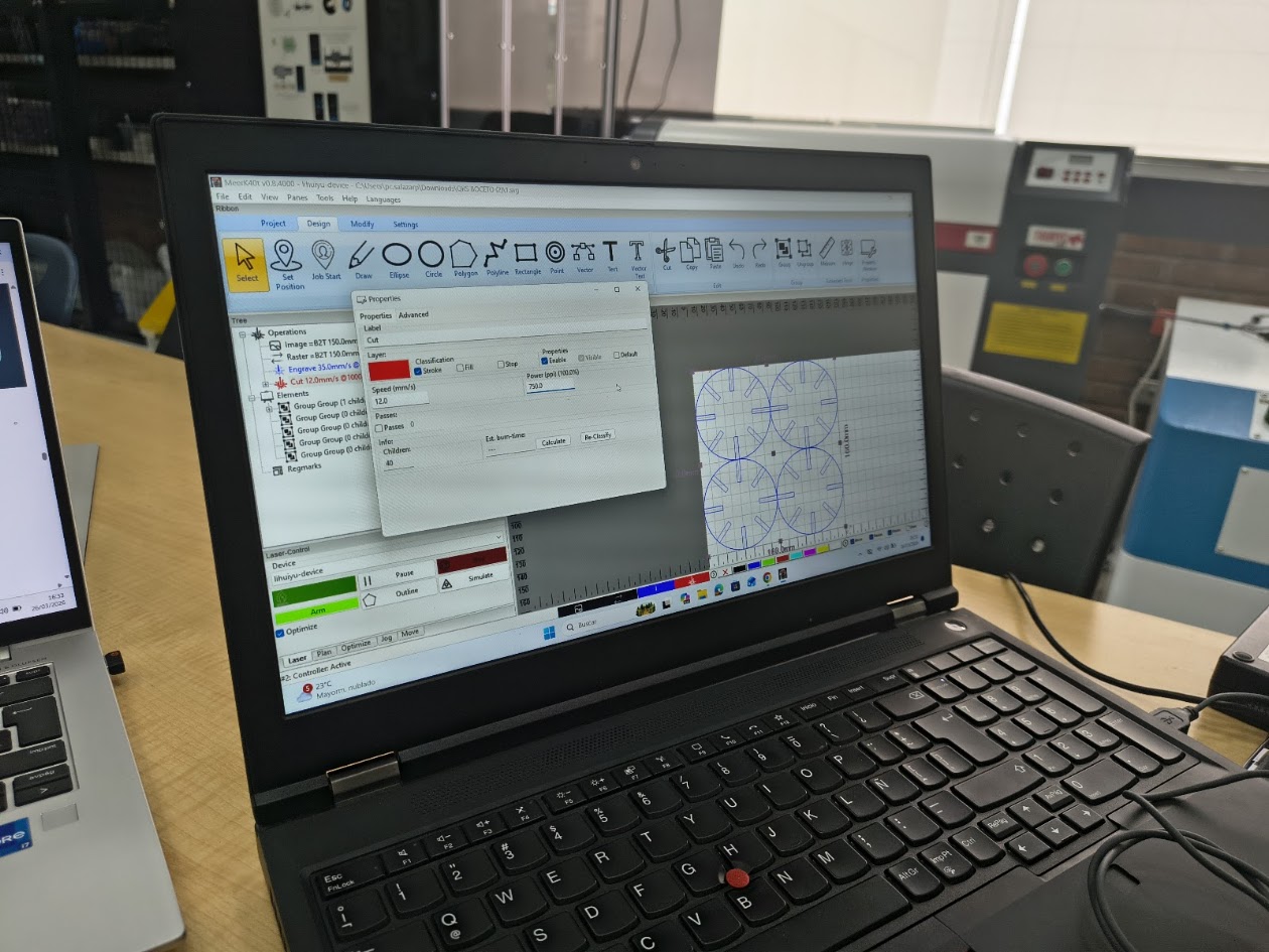
Label=cut; speed=12 mm/s, Power=75%, Classification=Stroke, Engrave 35 mm/s
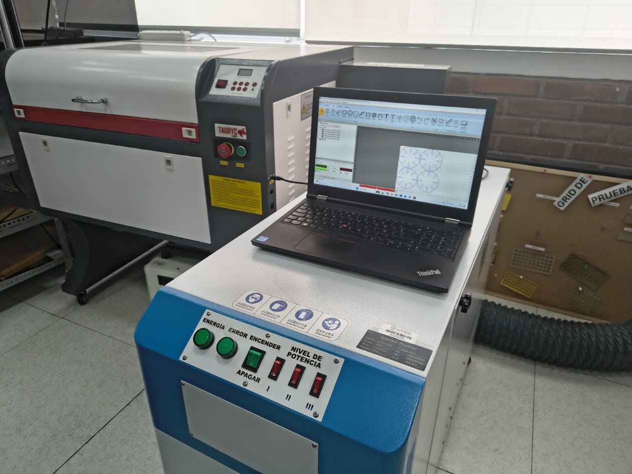
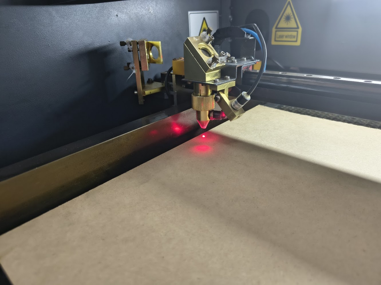
Connecting the computer
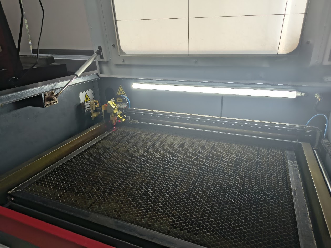
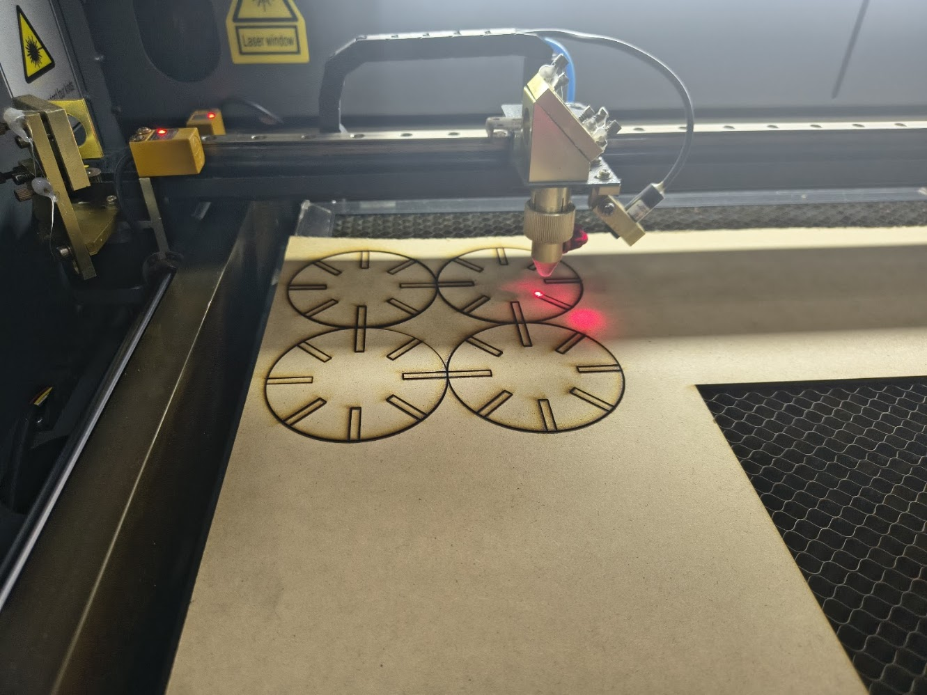
Calibrating the head
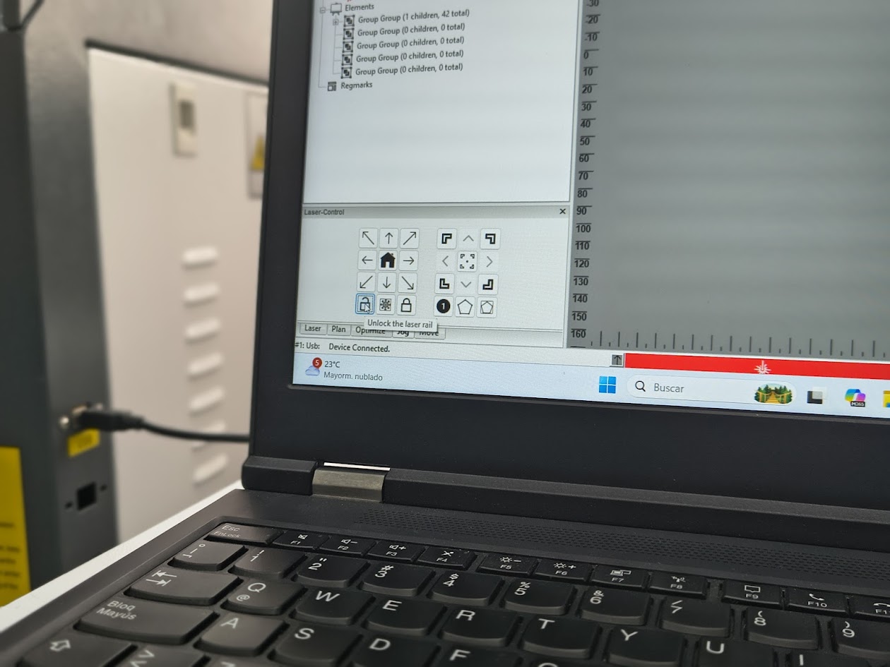
Open laser cutting
Cutting route
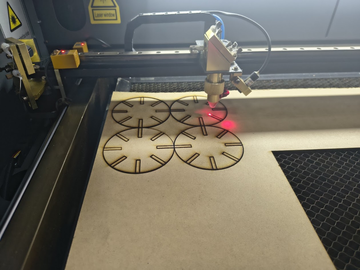
Final cutting
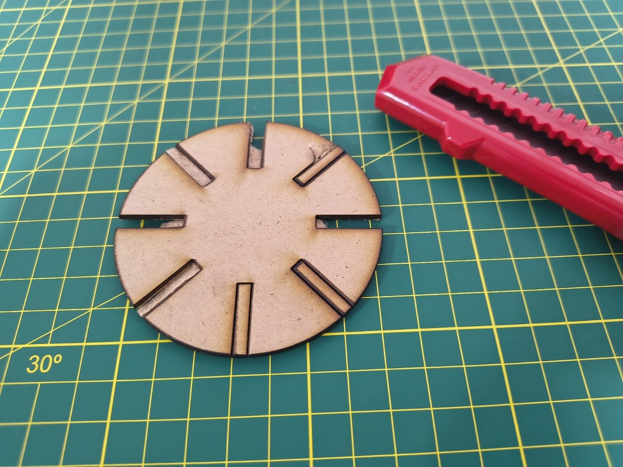
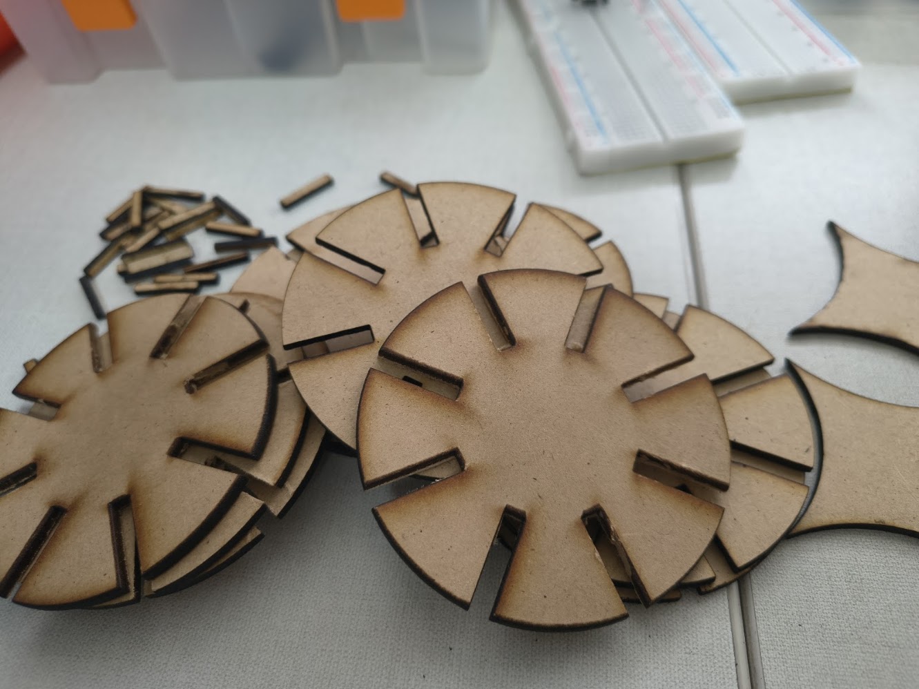
Cleaning the pieces
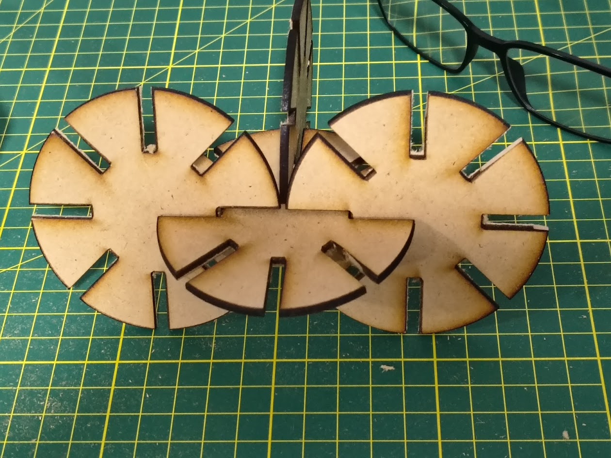
View of the pieces
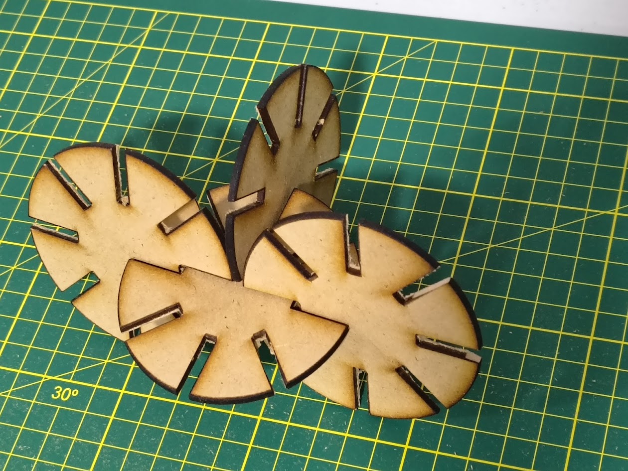
View of the pieces
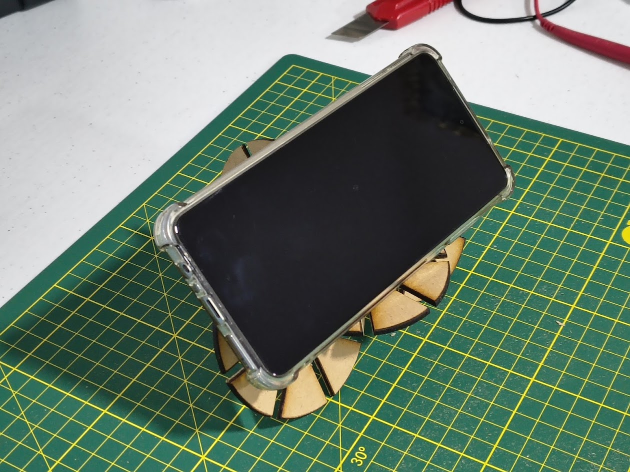
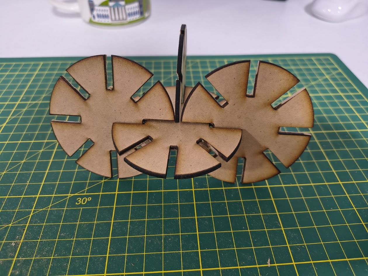
Phone holder
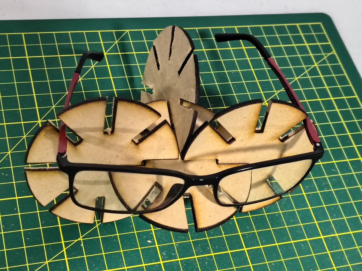
Glasses holder
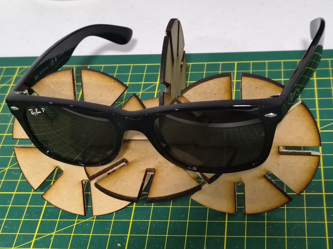
Sunglasses holder
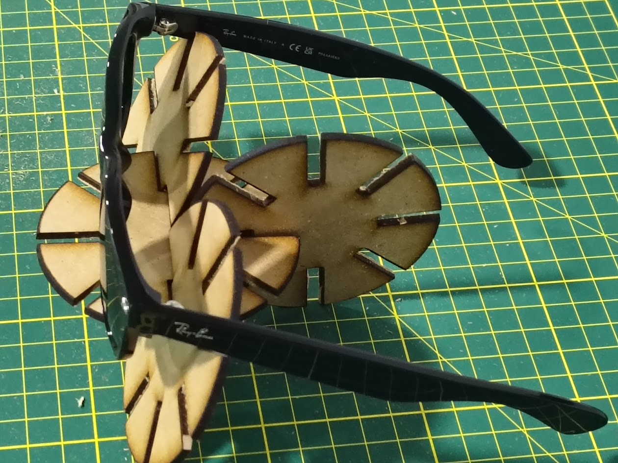
Sunglasses holder
Multifunctional parametric design
Video demonstration
4) Individual assignment 2 -Vinyl cutting
Problems
- Plotter didn't cut
- Incorrect vinyl
- Incorrect cutting mode
Solutions with Vinyl cutter
- Validate materials
- Validate cutting mode
- Domain the software
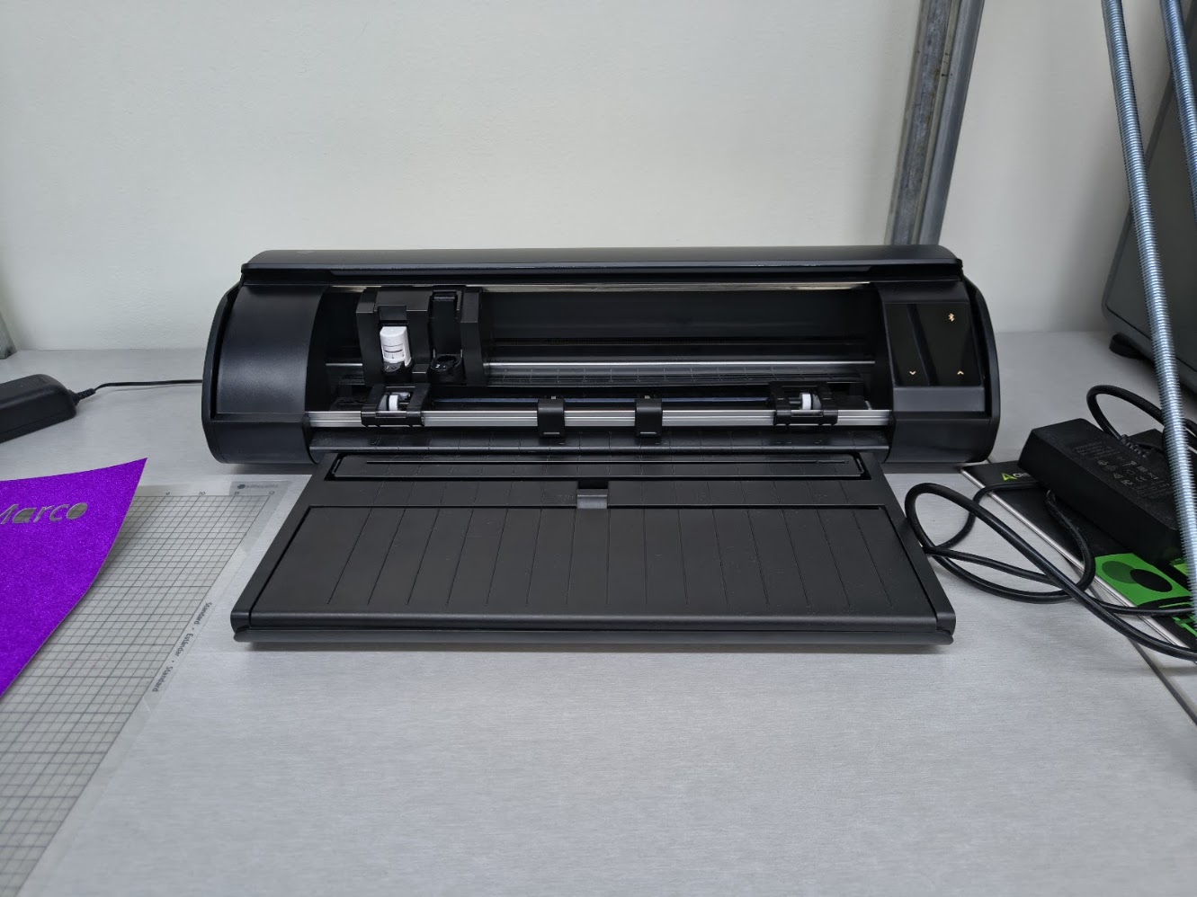
Sihouette Cameo 5 - cutting machine
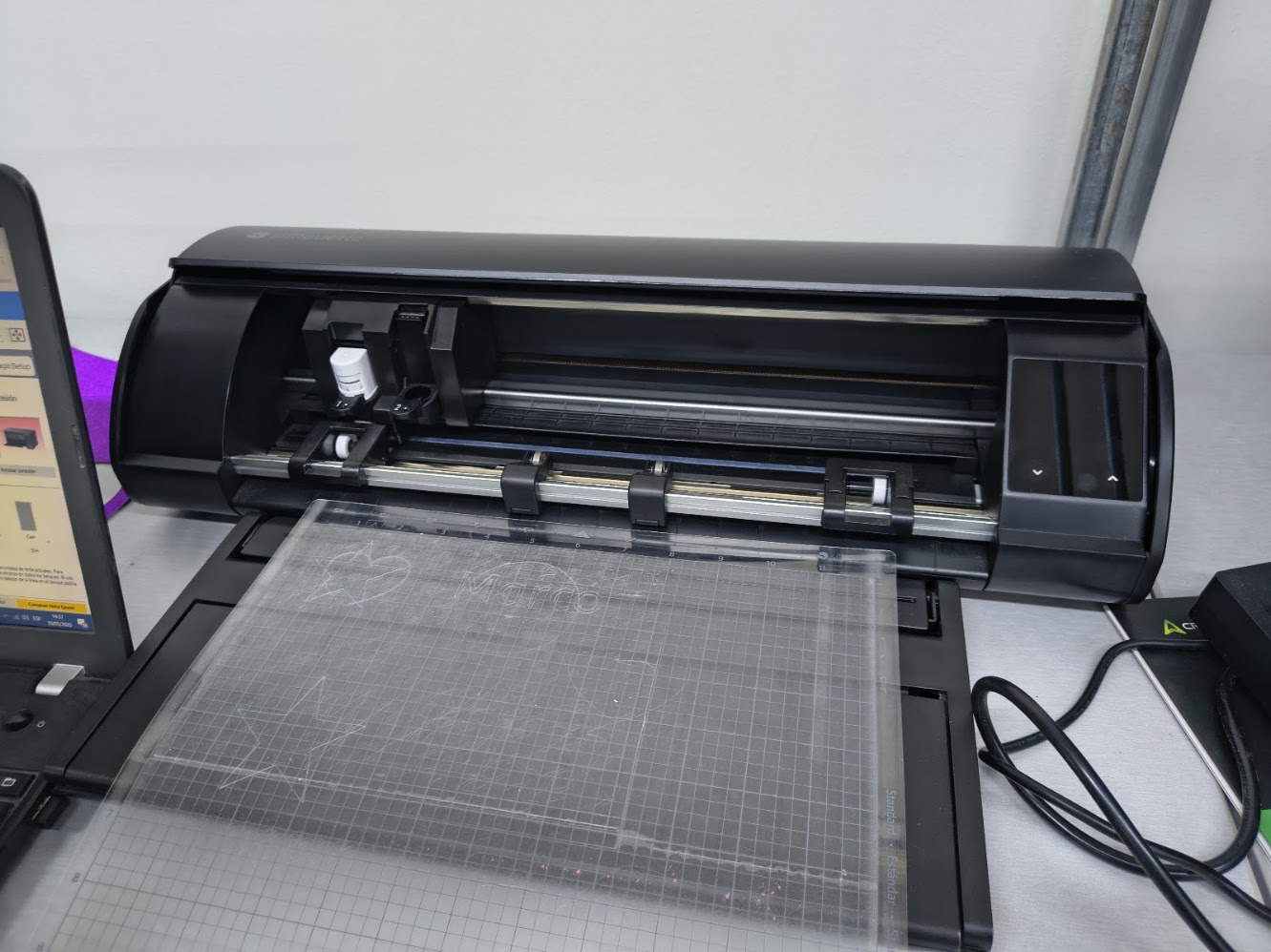
Sihouette Cameo 5 - cutting machine with vinil base
We used a 2mm MDF

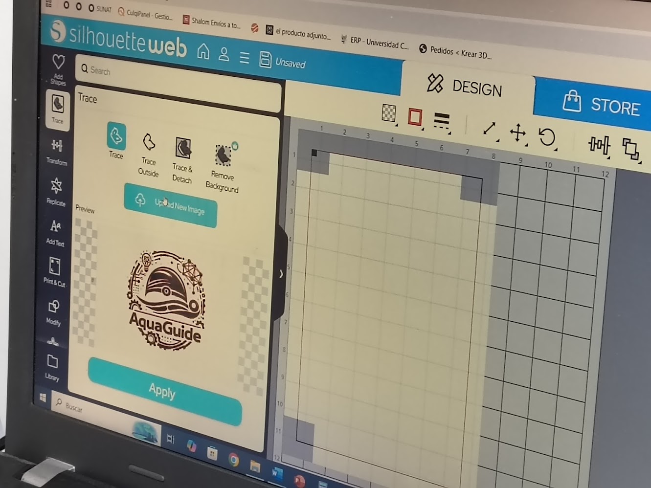
Designing indiviudal project logotype. Using Chat GPT to generate a logotype for my project and then I edited it in the software to cut it
Prompt: generate a logo, for swimmer with disabilities; considering sensors of distance, line detector, and others, and heart rate; the logo should be simple, modern, and easily recognizable
Upload logotype to the software
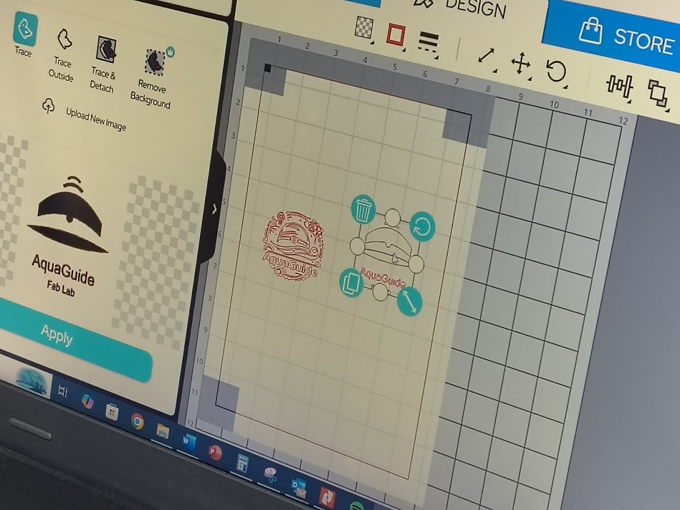
Upload logotype to the software and prepare it for cutting
       File SVG generated for cutting

      <svg viewBox="0 0 500 500" xmlns="http://www.w3.org/2000/svg">

        <!-- CAP -->
        <path d="M120 200 Q250 90 380 200 L380 240 Q250 190 120 240 Z" fill="black"/>

        <!-- SENSOR -->
        <circle cx="250" cy="210" r="12" fill="white"/>
        <circle cx="250" cy="210" r="5" fill="black"/>

        <!-- WAVE -->
        <path d="M100 270 Q250 240 400 270 Q250 300 100 270 Z" fill="black"/>

        <!-- SIGNAL -->
        <path d="M210 140 Q250 110 290 140" stroke="black" stroke-width="10" fill="none"/>
        <path d="M225 115 Q250 95 275 115" stroke="black" stroke-width="8" fill="none"/>

        <!-- TEXT AQUAGUIDE -->
        <text x="250" y="360" font-size="48" text-anchor="middle" font-family="Arial" fill="black">
          AquaGuide
        </text>

        <!-- TEXT FAB LAB -->
        <text x="250" y="400" font-size="28" text-anchor="middle" font-family="Arial" fill="black">
          Fab Lab
        </text>

      </svg>
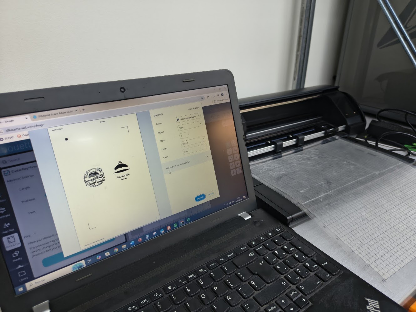
Printer preview and paper configuration
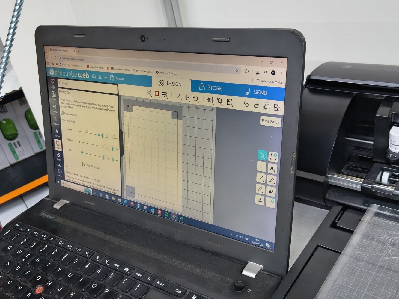
Review logotype dimension
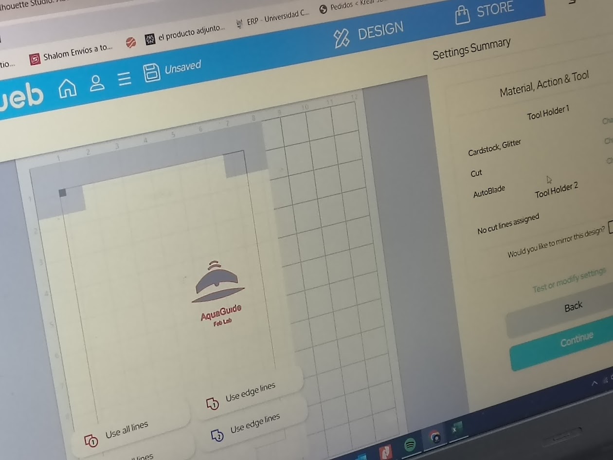
Cutting configuration
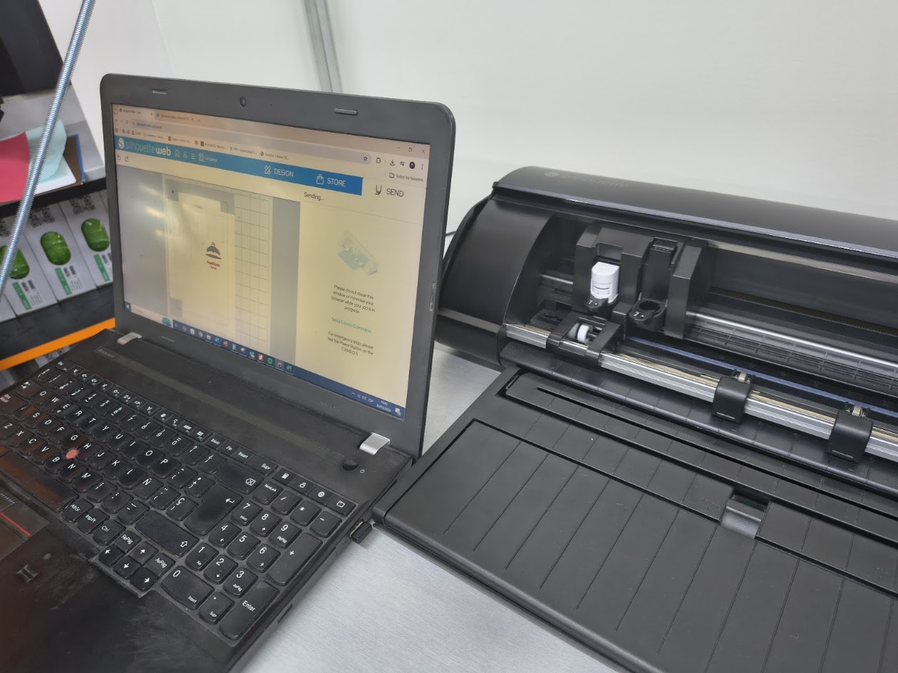
Sending files to the cutter
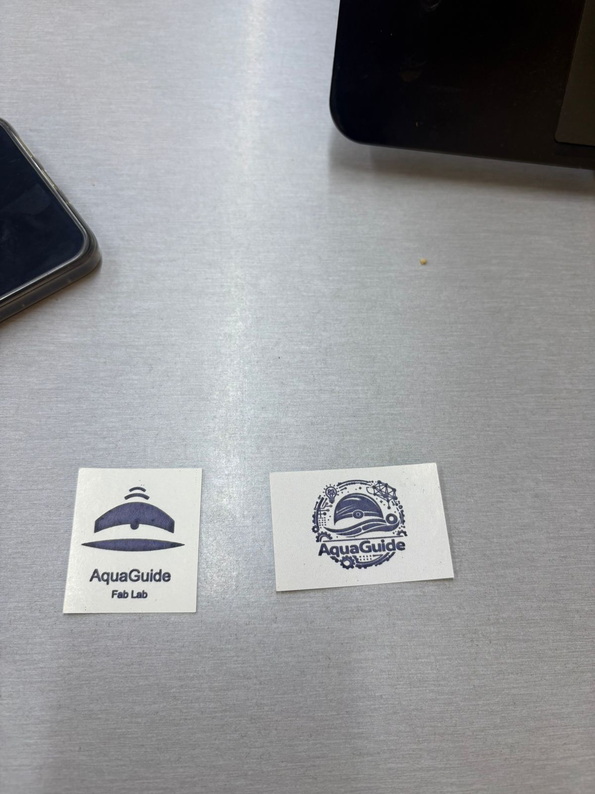
Final logotypes vinyl cutting
Video demonstration
4) Additional individual assignment
Laser cutting
- Multiples assemblies
- Hero shots
Vinyl cutting
- Setting & test cup proof
- Peeling process
- Type of tape
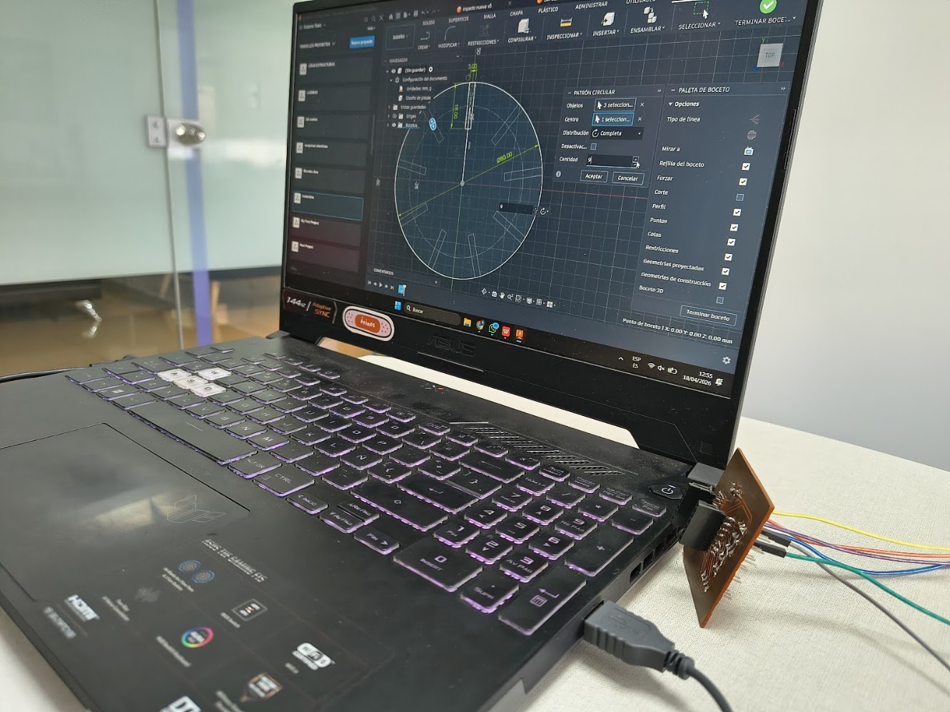
Repeat parametric design with Autodesk Fusion
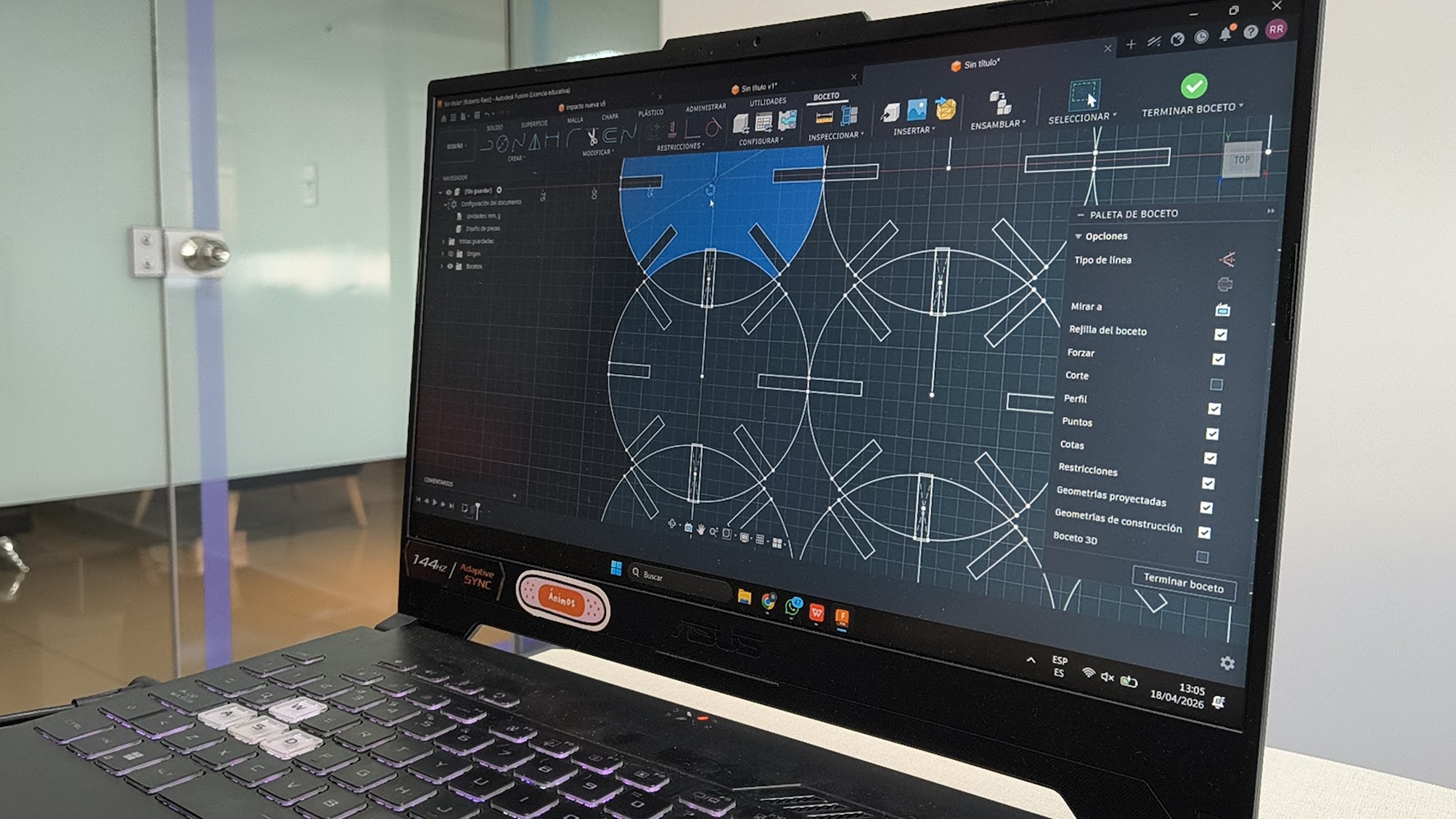
Repeat parametric design with Autodesk Fusion
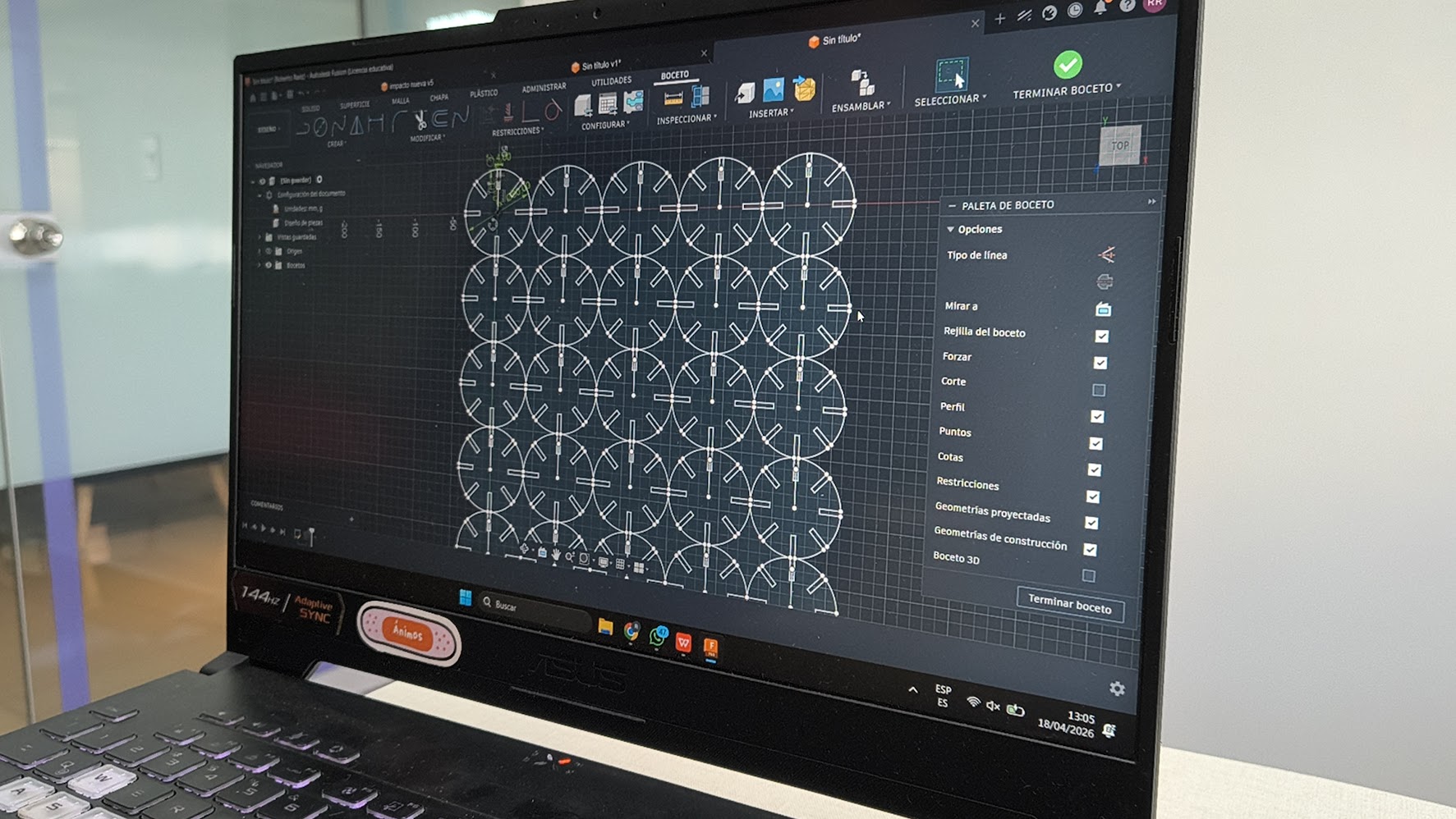
Repeat parametric design with Autodesk Fusion
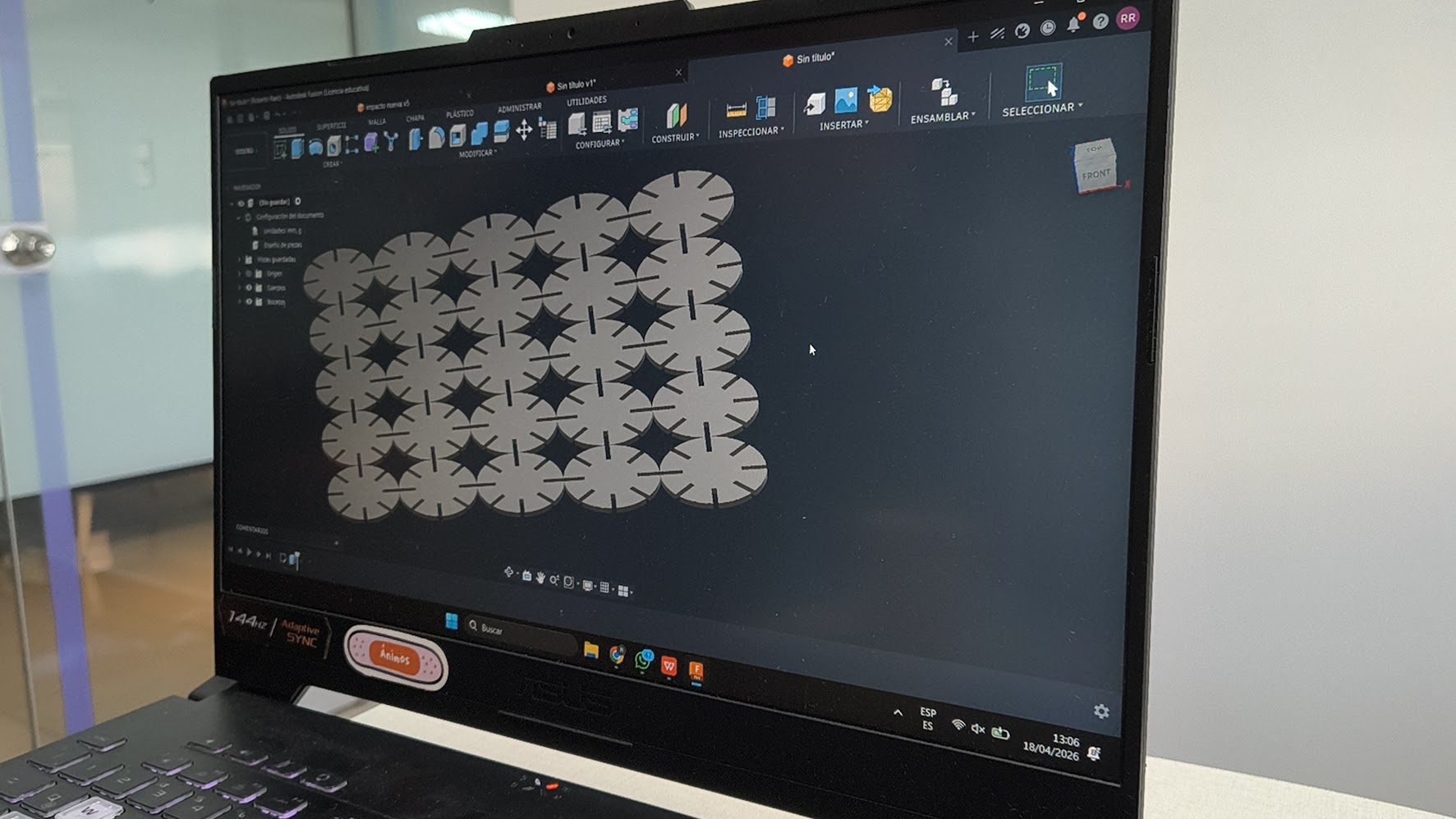
Repeat parametric design with Autodesk Fusion
Setup the Tauric 9600 laser machine
Working the laser machine
More circles
Artistic ornament
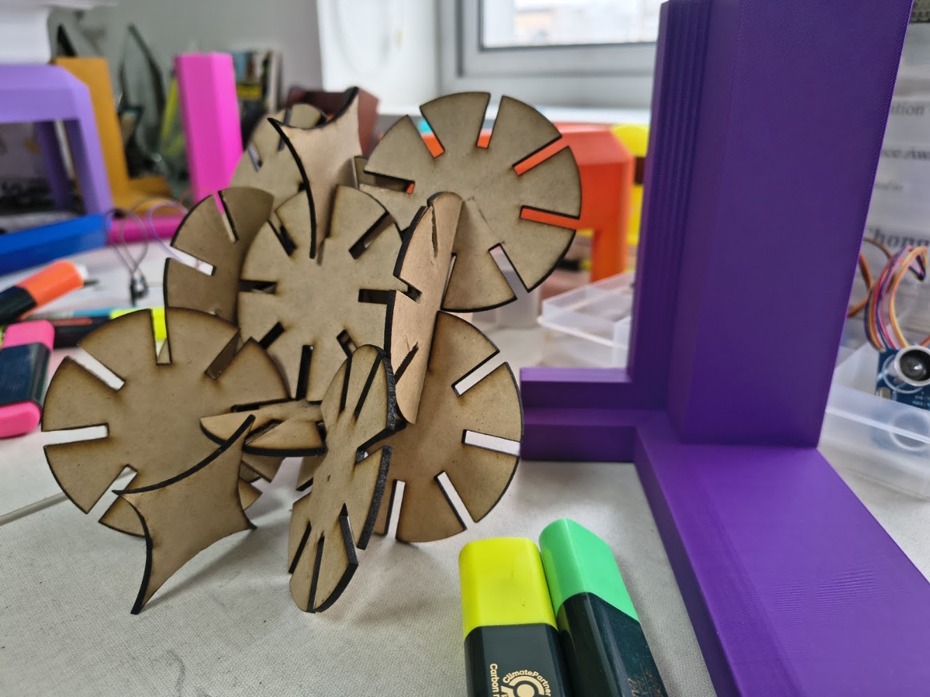
Artistic ornament 2
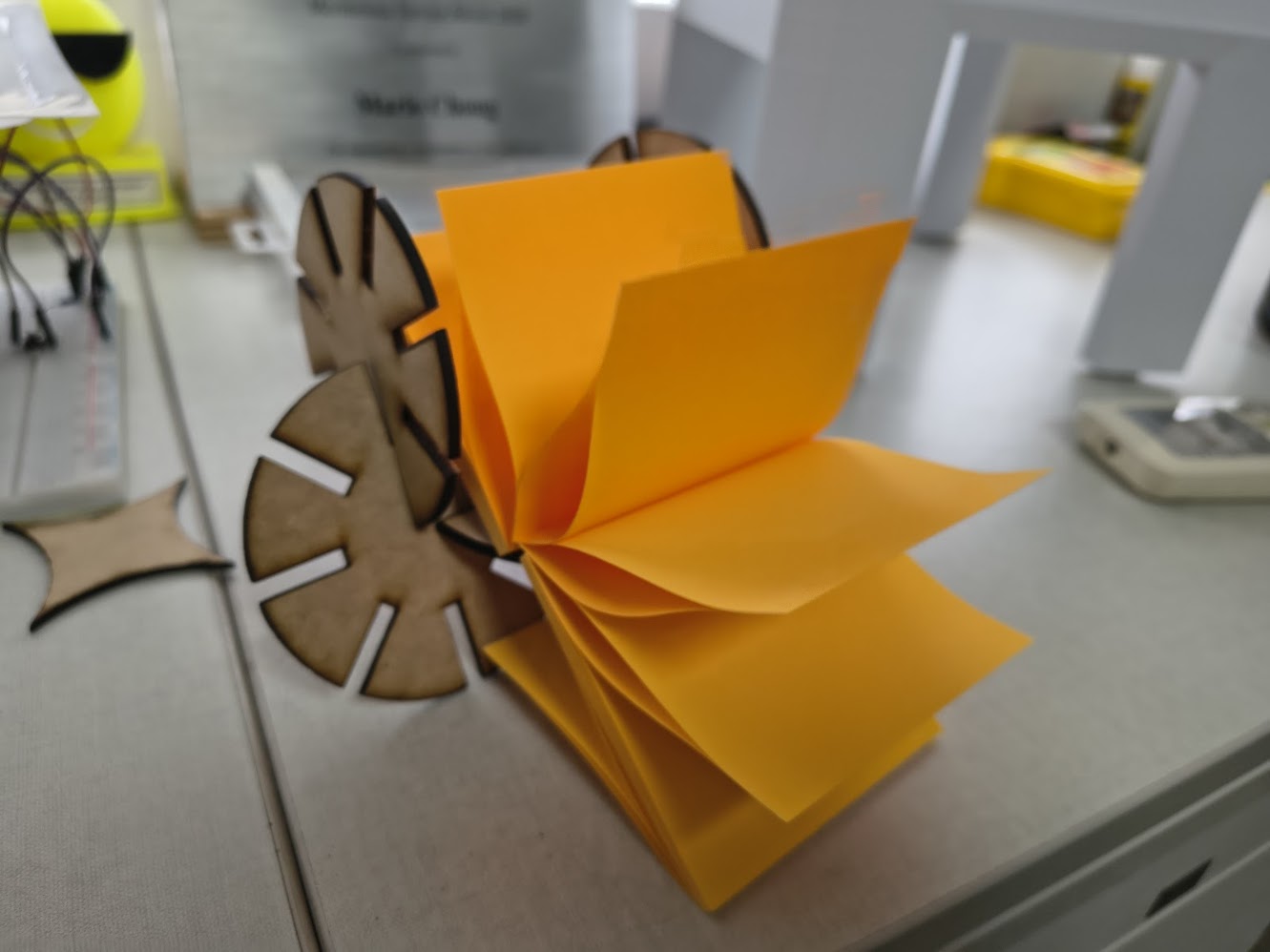
Post it - Good vibres - see video
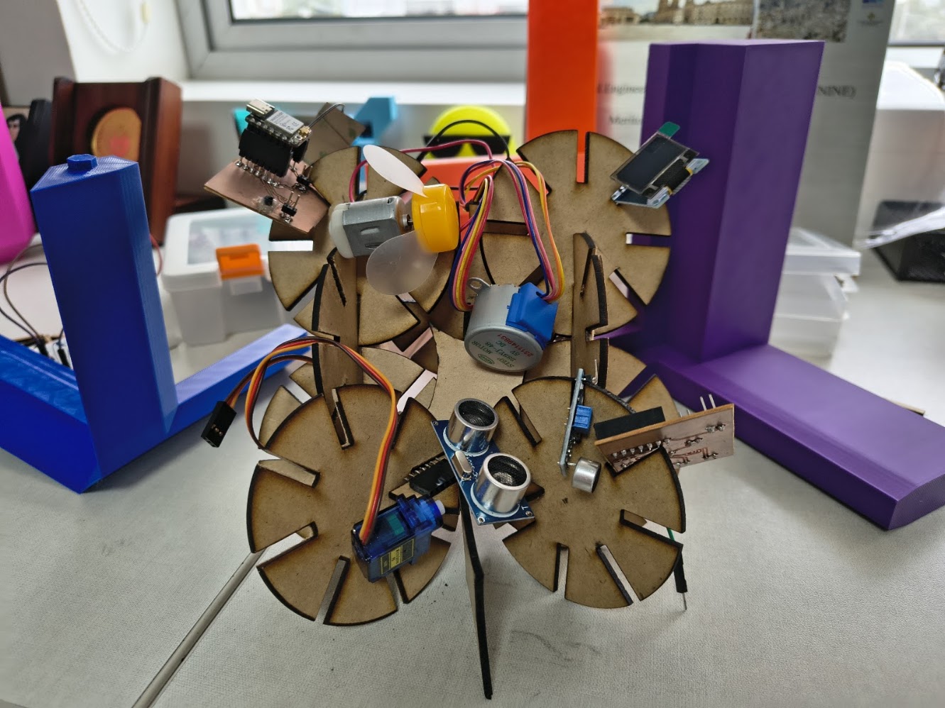
Devices organizer
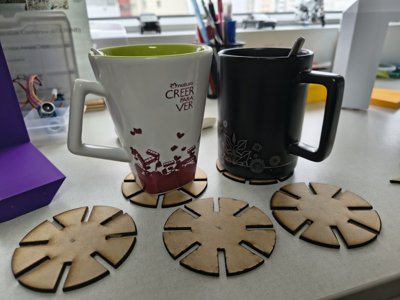
Cup holders

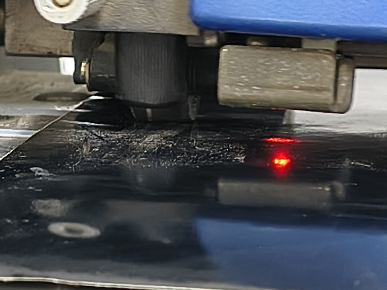
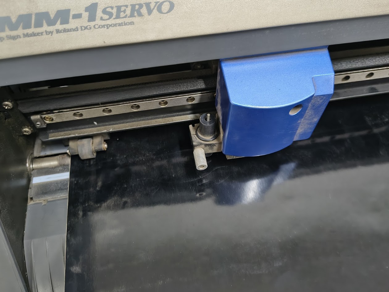
Working with "Rolando" Cutting Machine

Roland CAMM-1 Servo

Setting the machine and vinyl
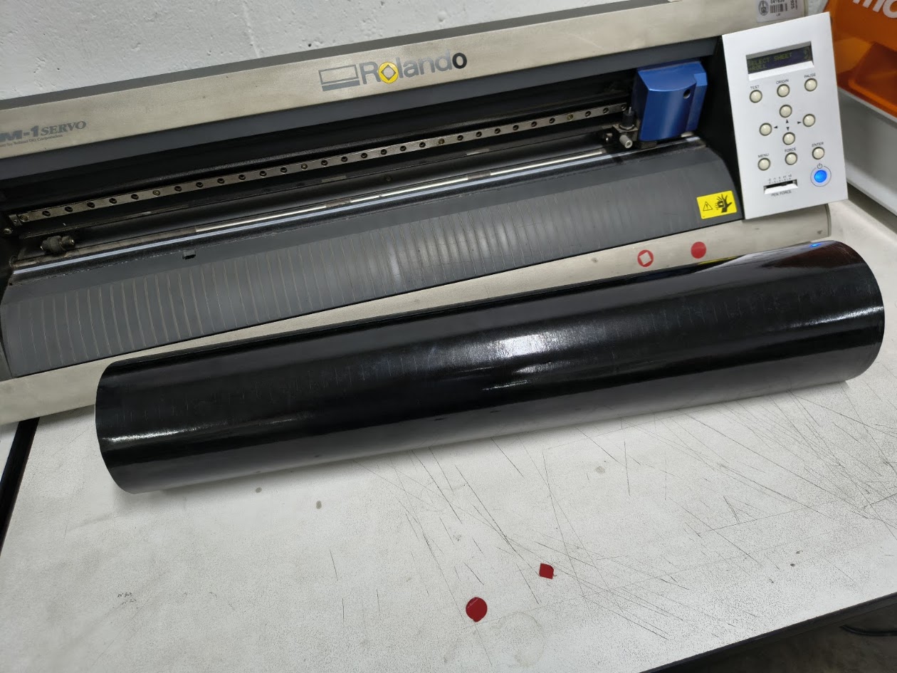
Setting the machine and vinyl
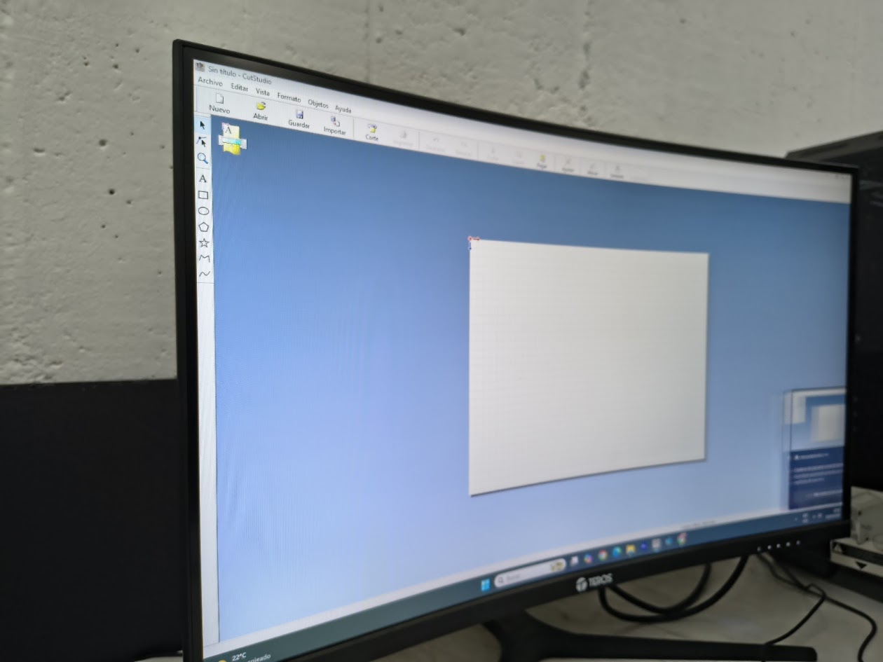
Cut Studio Software
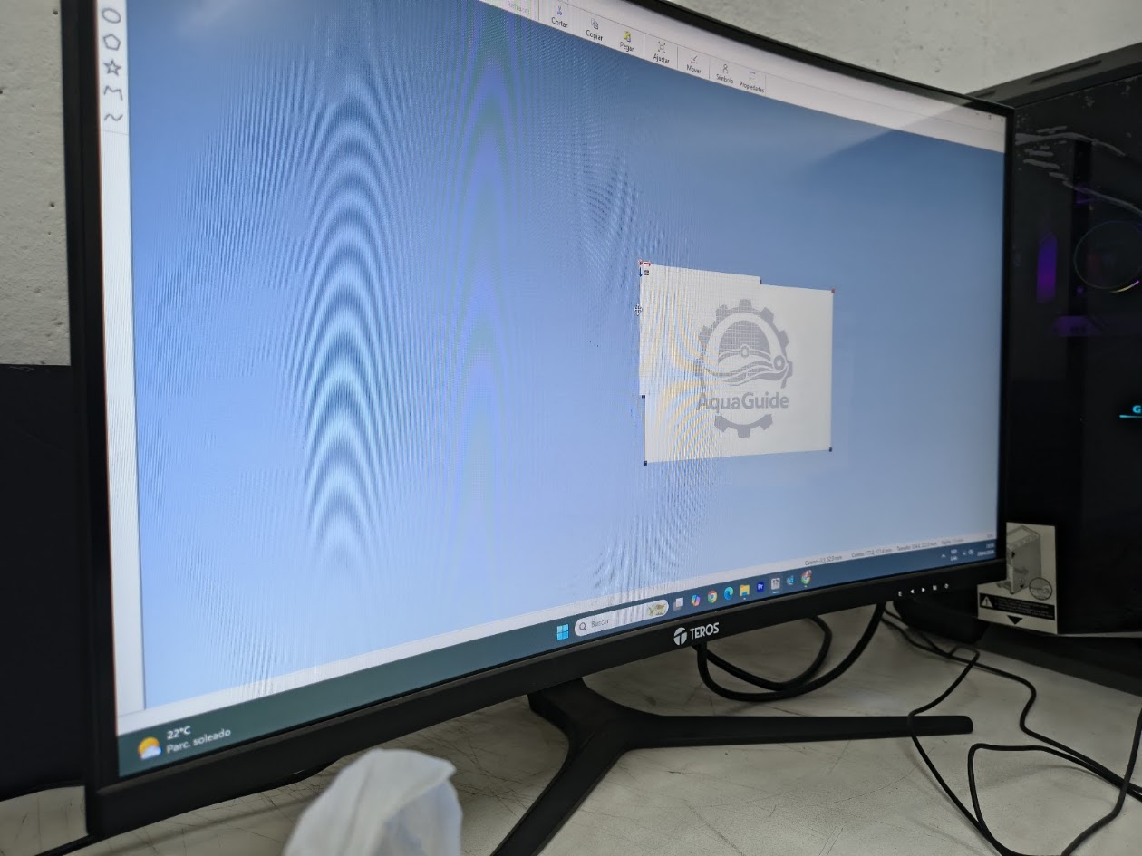
Up load the image
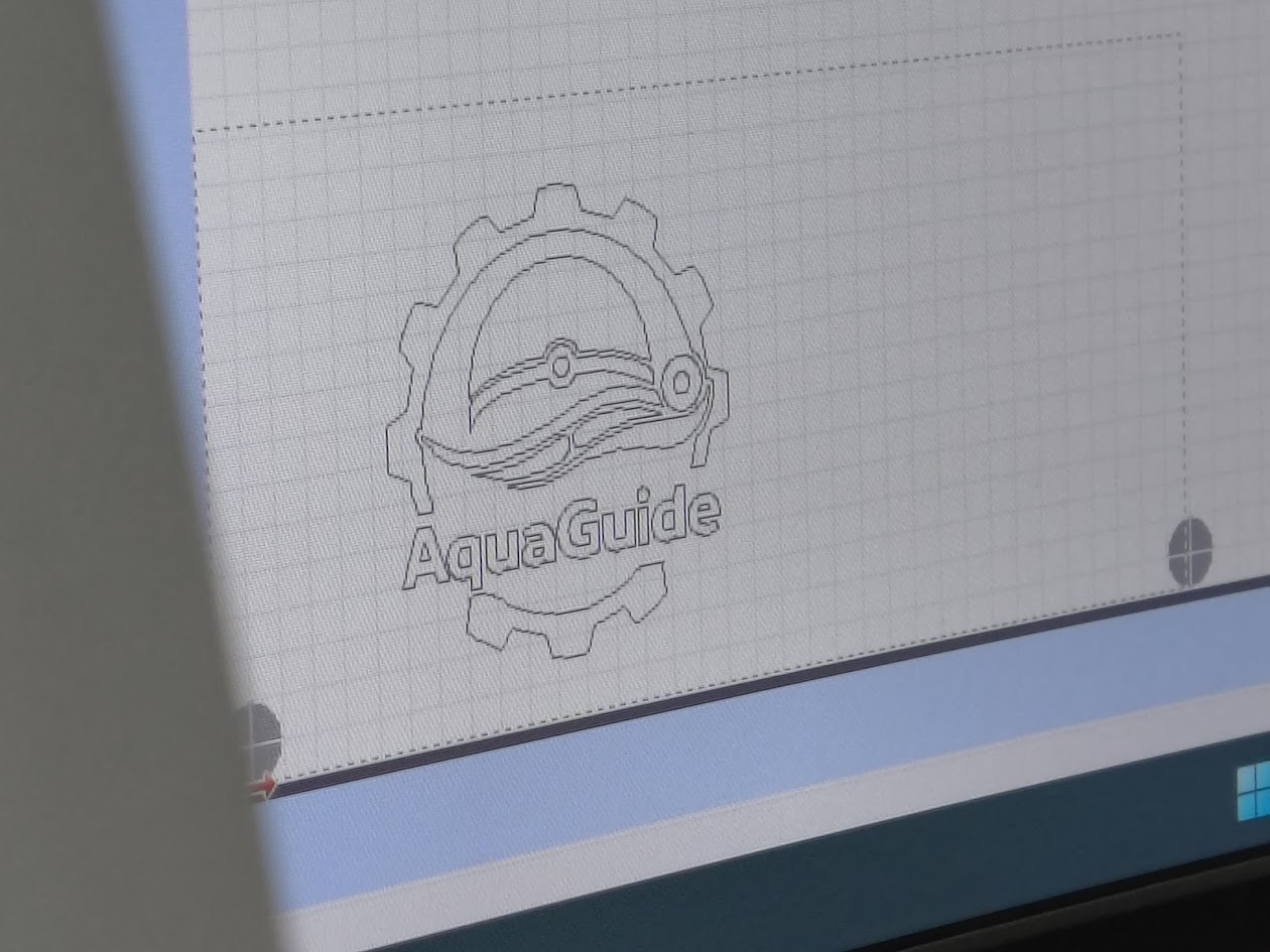
Configure contour
Cutting vinyl
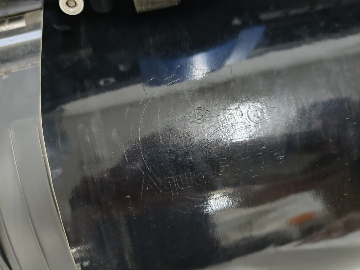
Cutted image
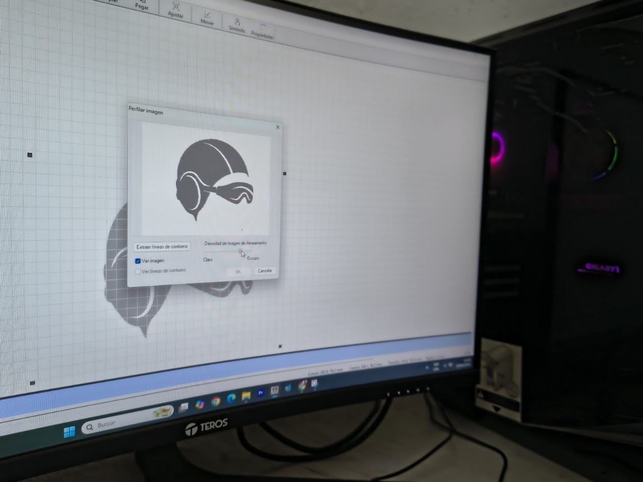
Upload image 2
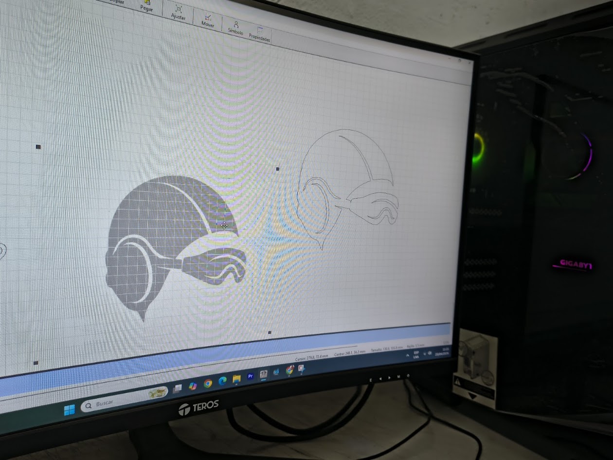
Image and contour
Cutting image 2
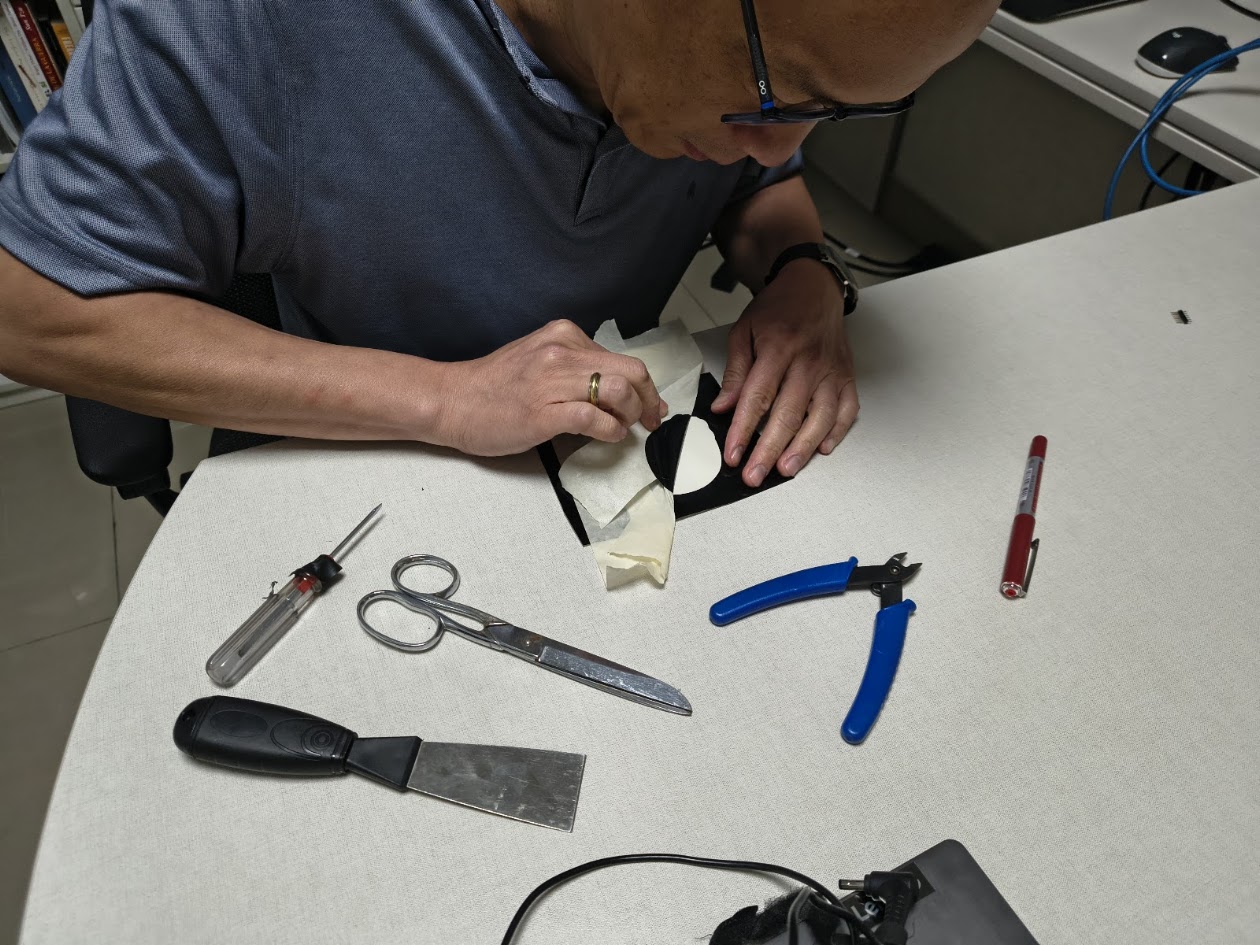
Using masking tape and other tools
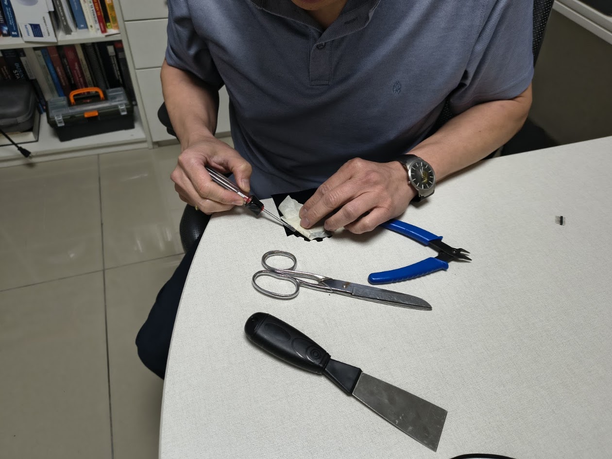
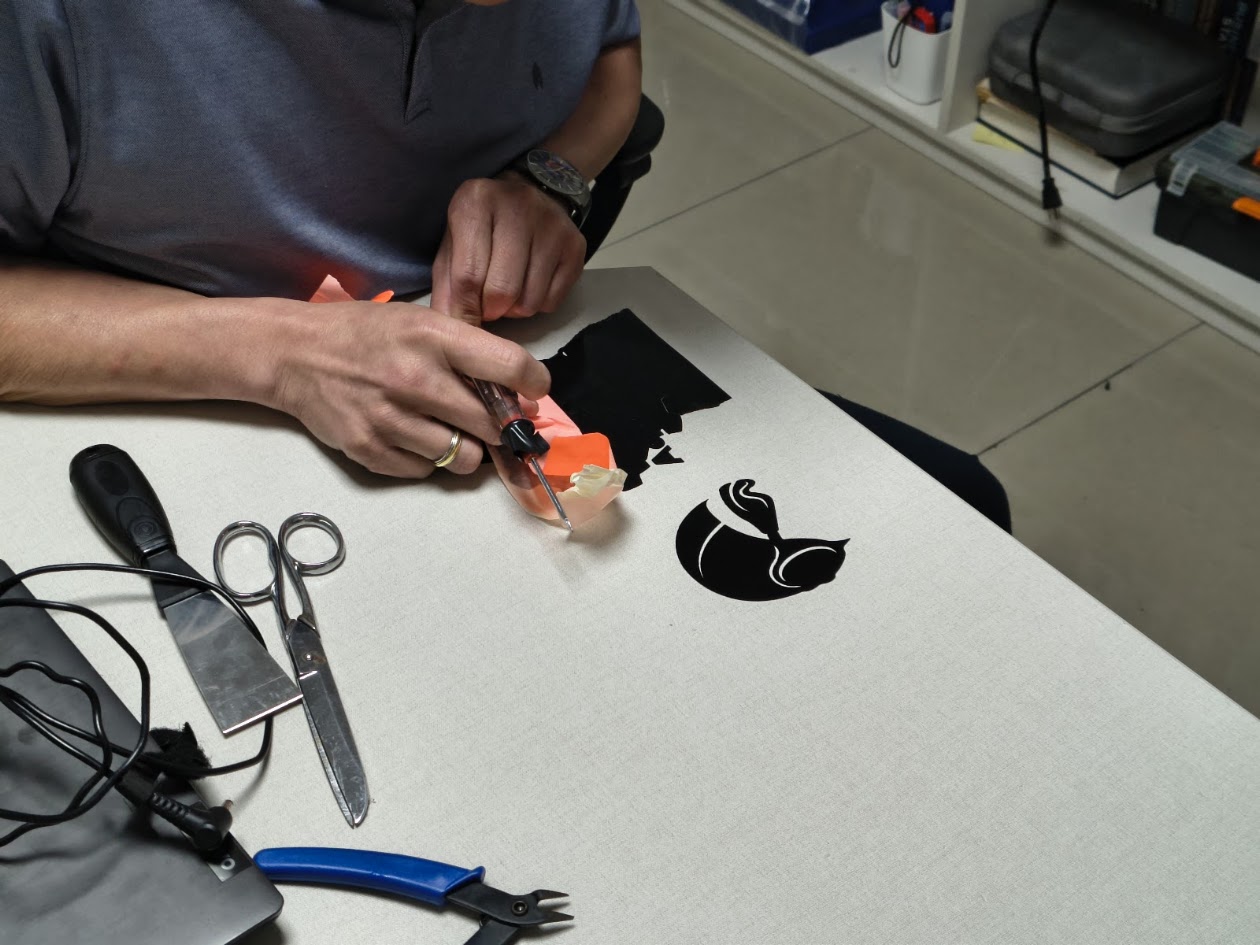
Take off image 2
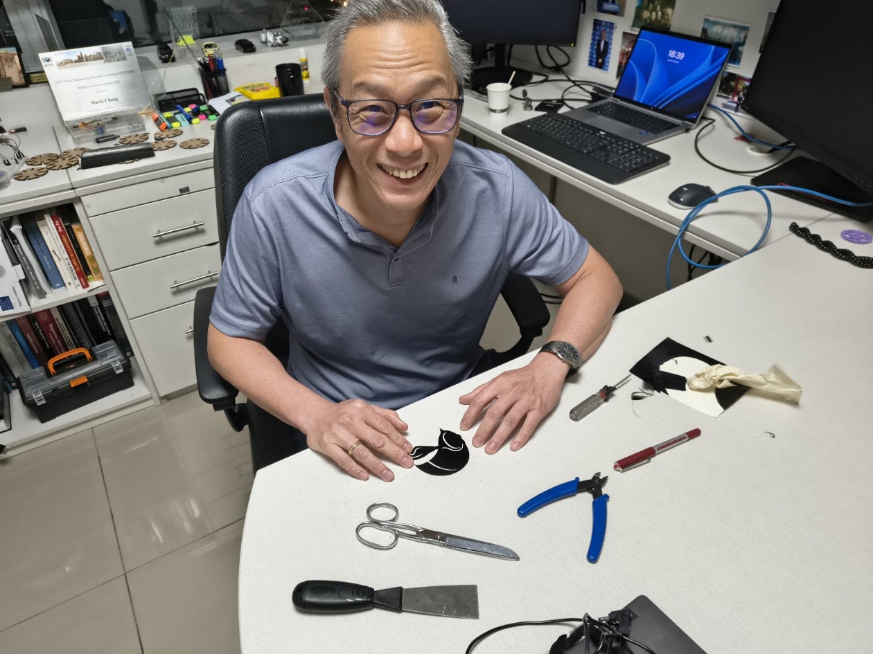
Image 2 ready
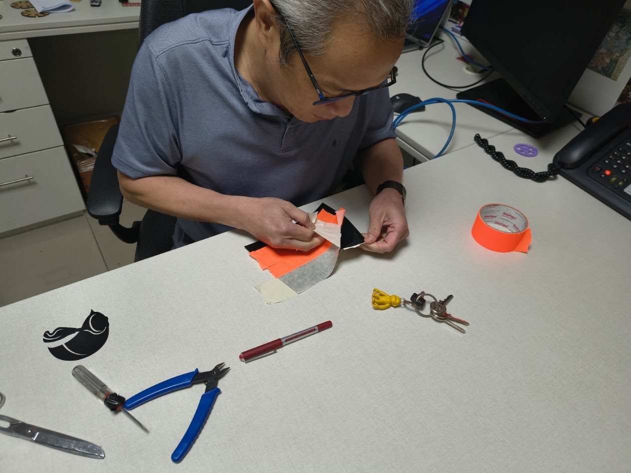
Using masking tape and other tools for image 1
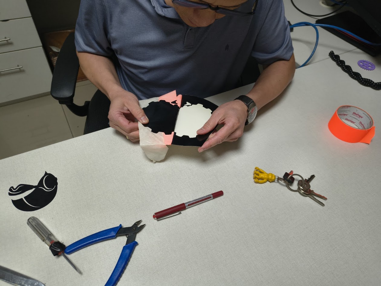
Taking off image 1
Not easy
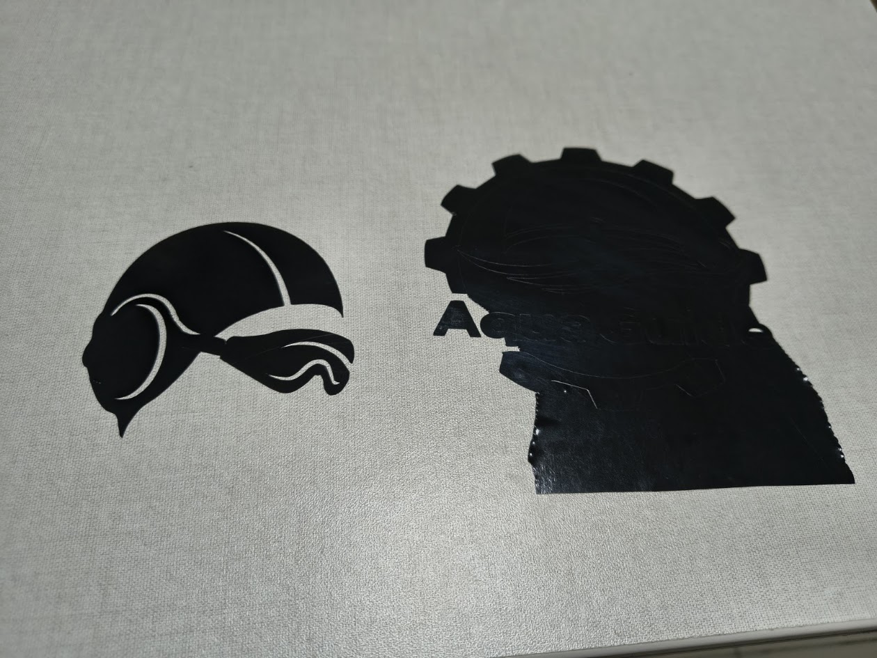
Image 1 and image 2
Both image ready
Video demonstration
5) References files
We learn about parametric design, use the laser cutting and vinil cutting
6) Final results
What did you learn? What would you improve next time?
- Linked to the group assignment page - More information at Fab Lab Peru - Group Assignment: https://fabacademy.org/2026/labs/lima/#page-top
- Reflected on your individual page what you learned of your labs safety training
- Explained how you created your paremetric design - On group and invividual assignments
- Documented how you made your press-fit construction kit - On individual assigments
- Documented how you made something with the vinyl cutter - On individual assignments
- Included your original design files
- Included hero shots of your results - On this web page