Assignment requirements
Assignment
- Model (raster, vector, 2D, 3D, render, animate, simulate, ...) a possible final project
- Compress your images and videos
- Post a description with your design files on your class page
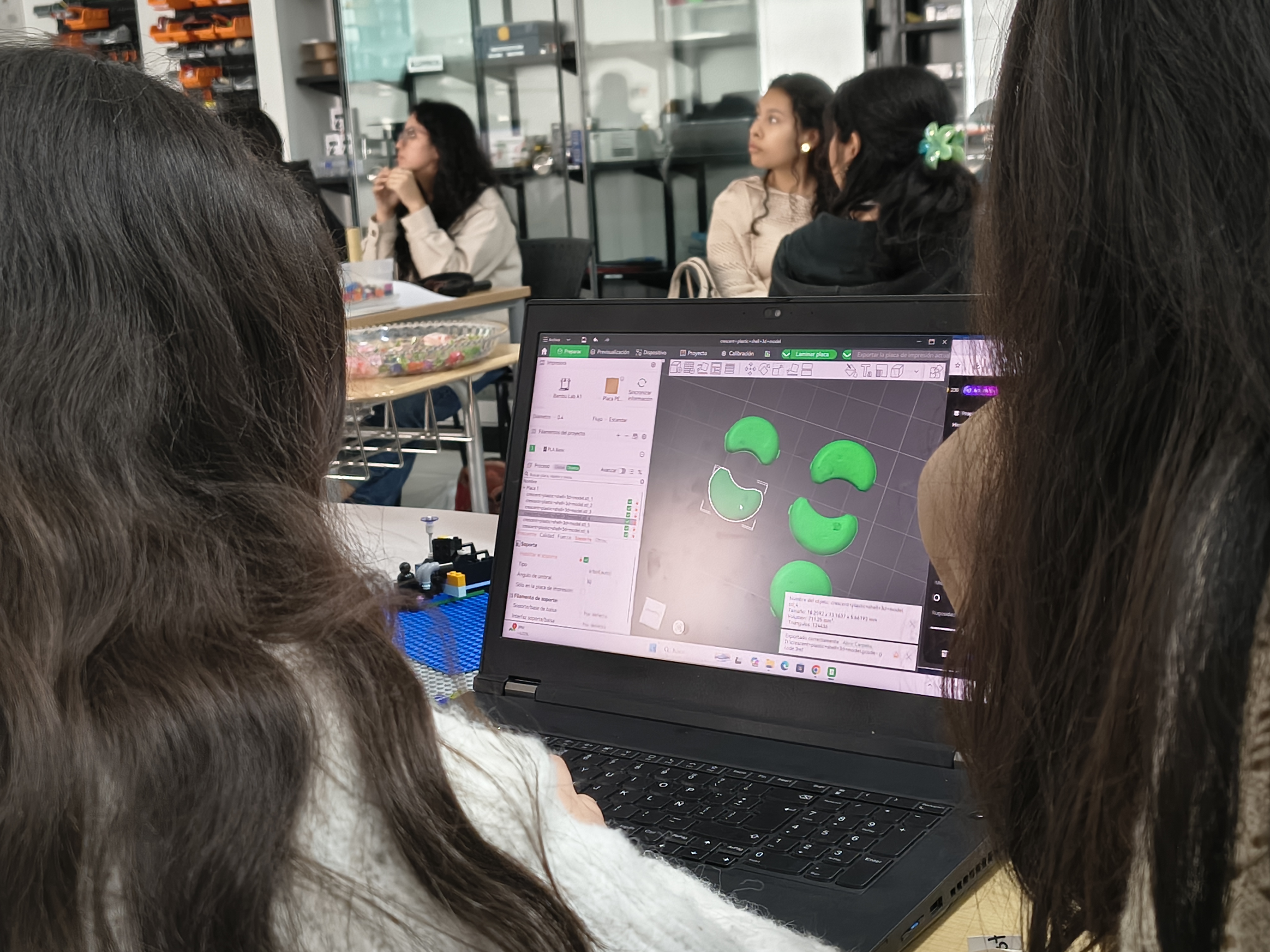
2d and 3D software
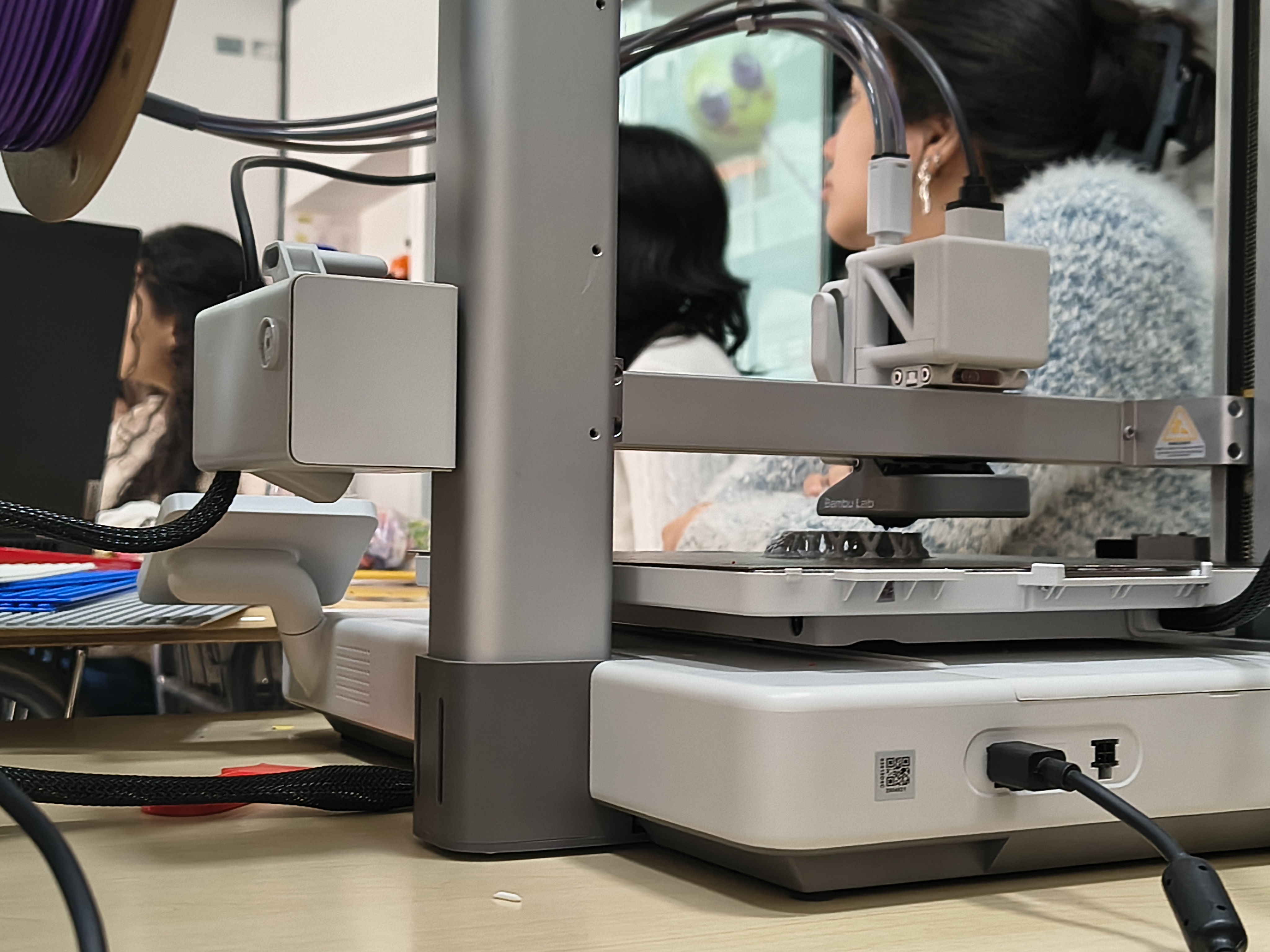
Part of the final model in 2D and 3D
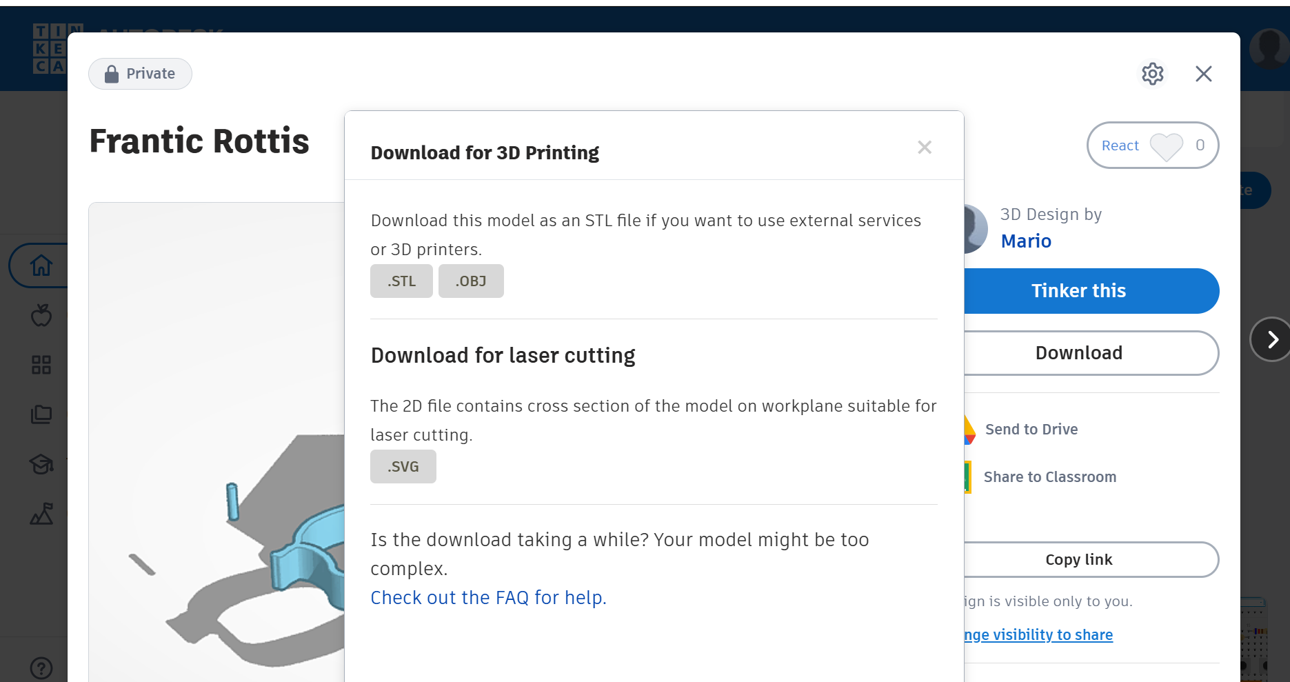
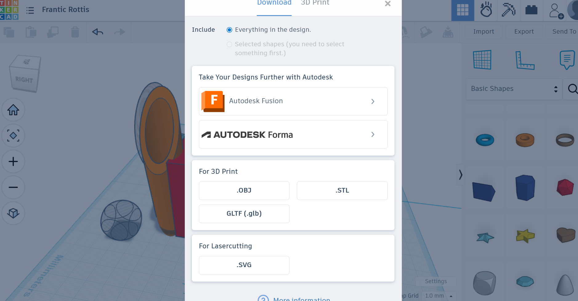
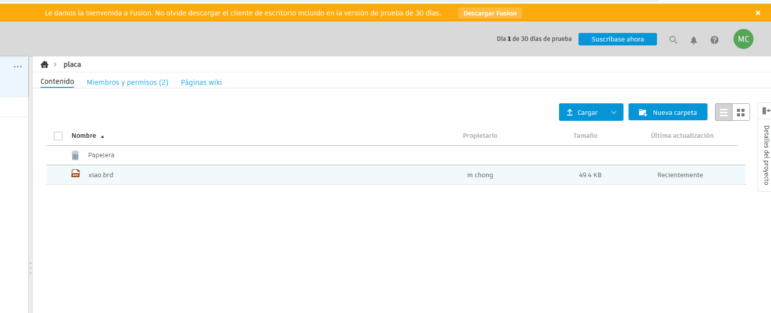
Upload .zip with source files.
1) Introduction
The goal is sketch the final project using 2D and 3D software and compress images and videos
2) 2D Software
For more details visit Fab Lab Peru
1. Manufacturing & Engineering
- AutoCAD / AutoCAD LT: product design, 2D precision
- SolidEdge (2D Drafting): professional-grade 2D drafting tool for free. Mechanical parts and product schematics
- DraftSight: Works with .dwg files. Engineering teams
- LibreCAD: Open-source. Simple 2D technical drawings
2. Visual Mockups & Concept Design
- Vector Graphics: packaging, labels, or flat icons
- Affinity Designer 2: isometric grids (which make 2D look 3D)
- Adobe Illustrator: branding and packaging. Wrap 2D designs onto photos of 3D products
- Figma: websites, flat products
3) 3D Software
1. Manufacturing & Engineering
- SolidWorks:for mechanical engineering and has a robust simulation tools for professional engineers
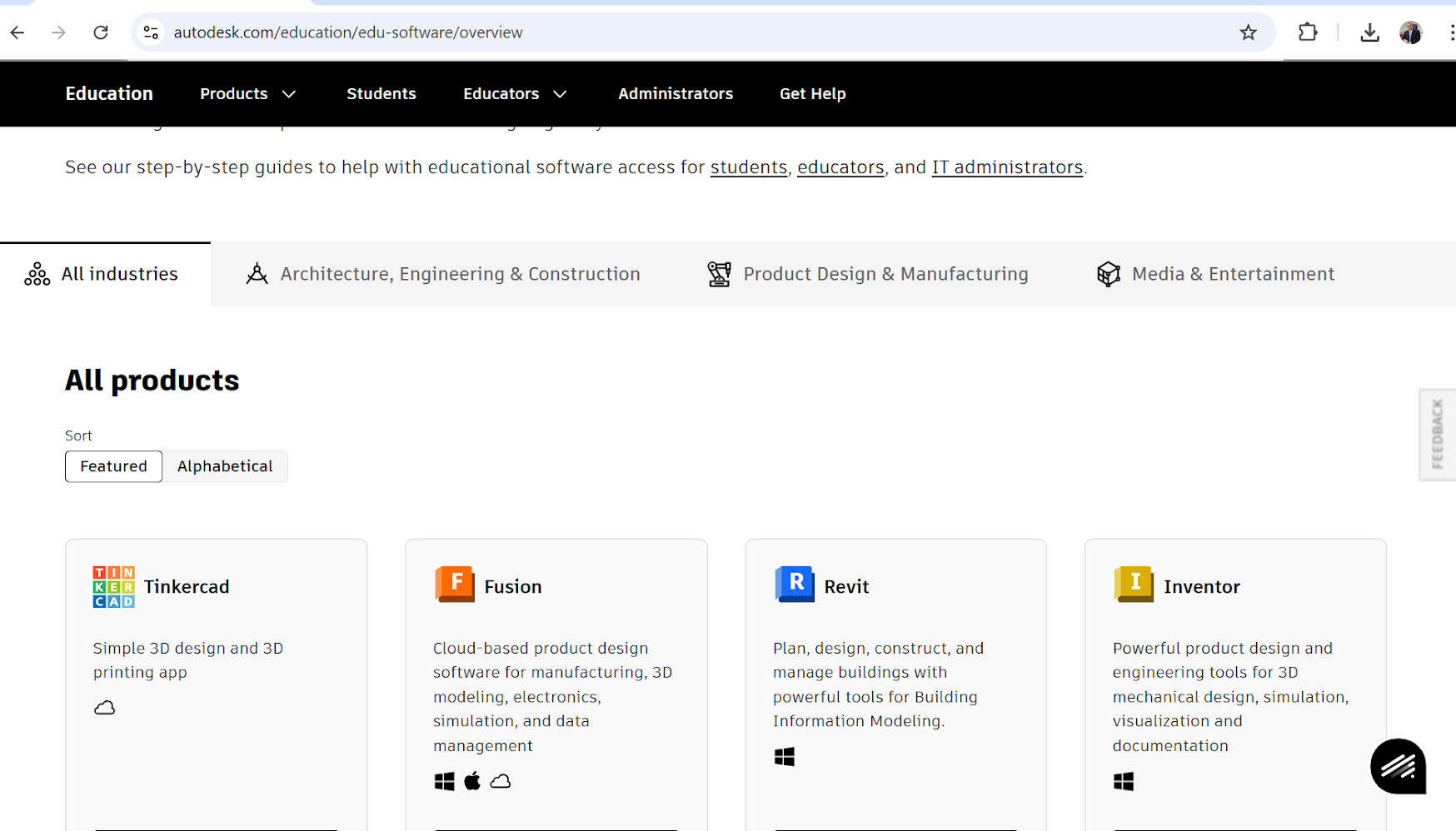
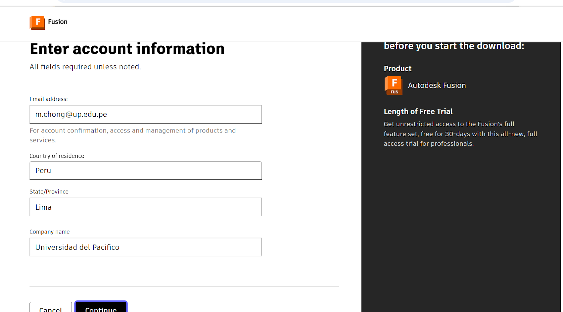
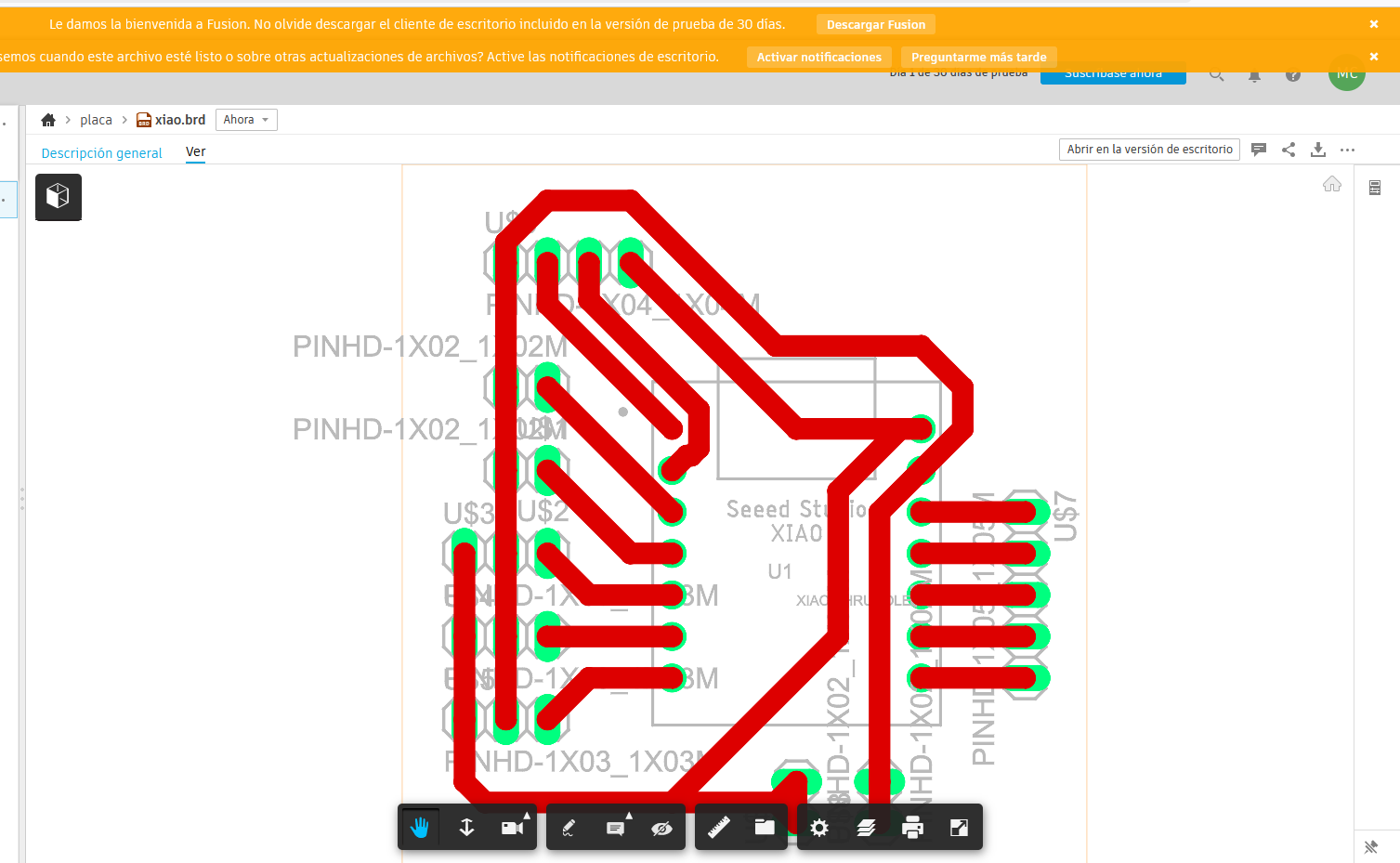
- Autodesk Fusion (formerly Fusion 360): versatile tool: cloud, CAD (Design) with CAM (Manufacturing) and CAE (Testing)
- Shapr3d: intuitive tool and produces professional-grade files
- Onshape: CAD platform, works remotely across different operating systems
2. Visual Mockups & Concept Design
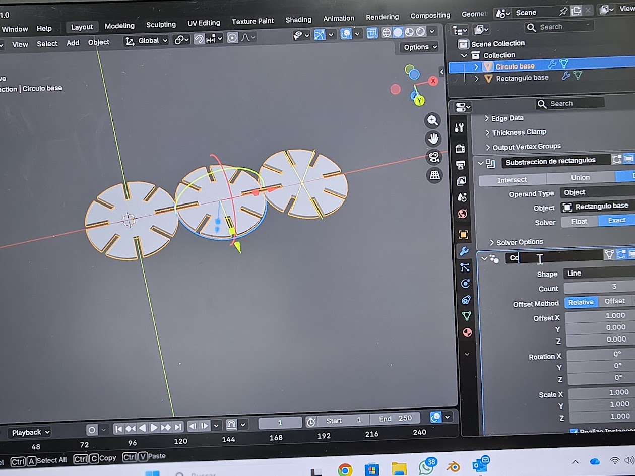
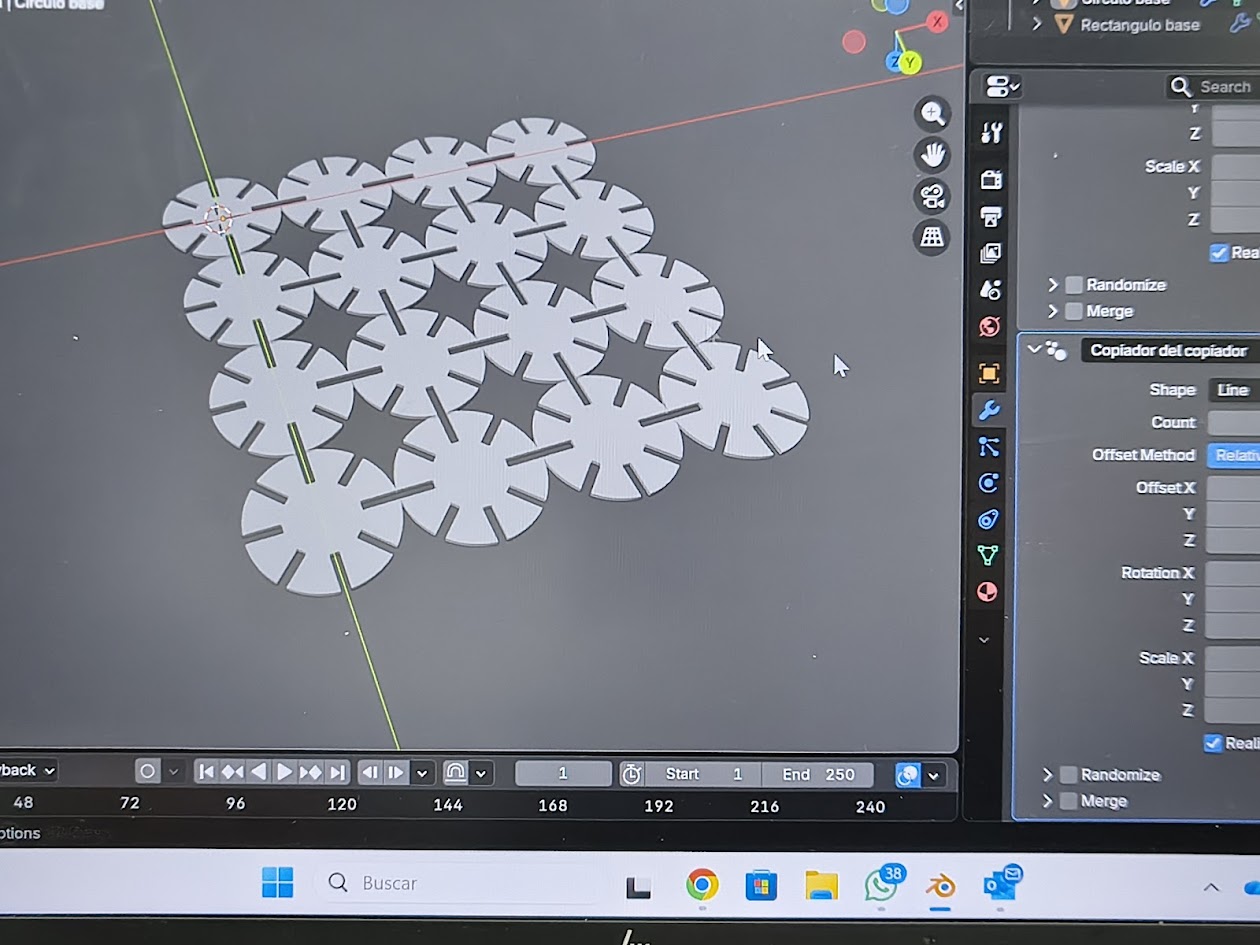
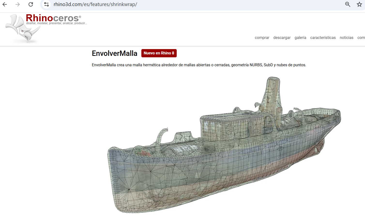
- Rhino 8 + Grasshopper: complex products, organic shapes. Grasshopper allows parametric design, creating patterns.
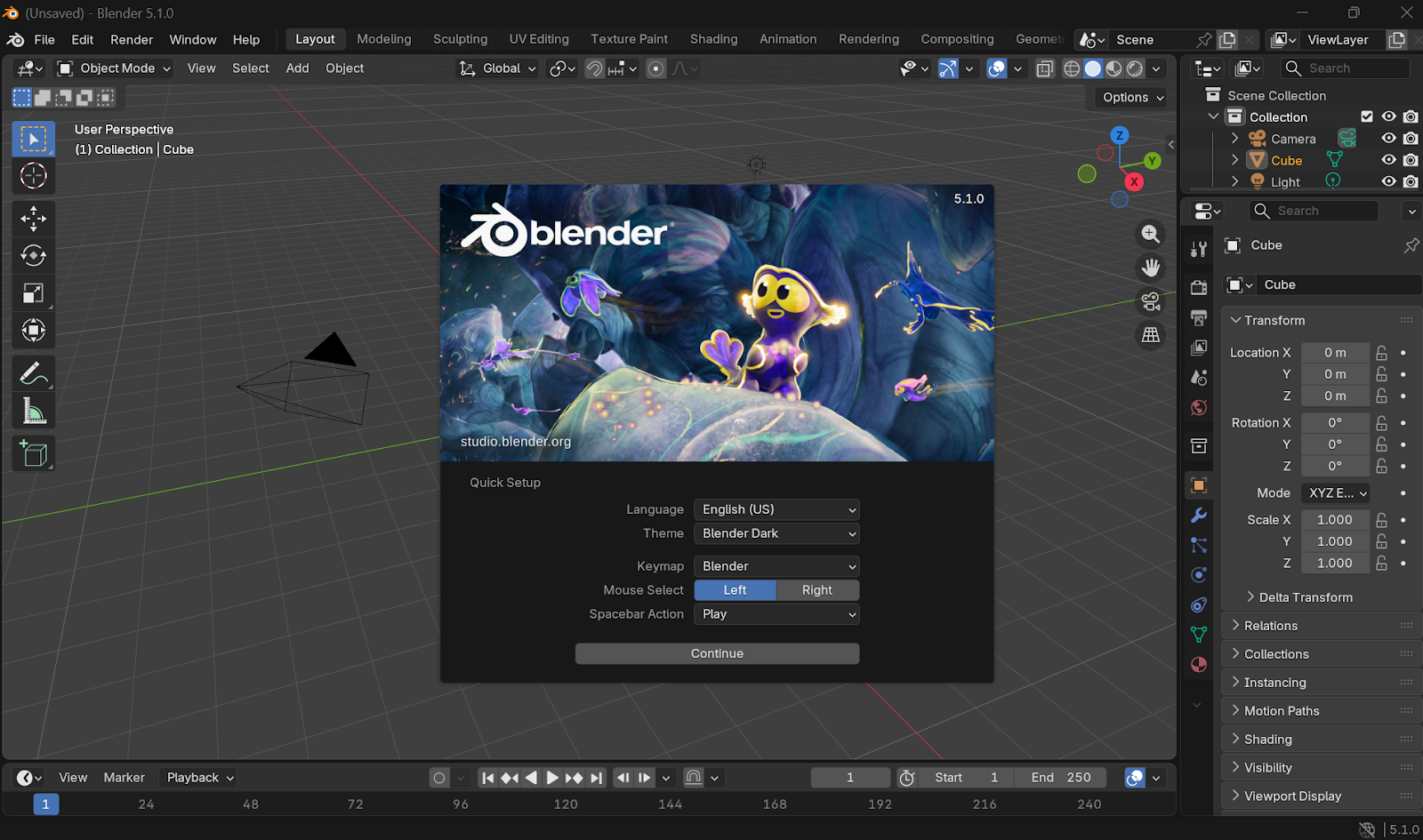
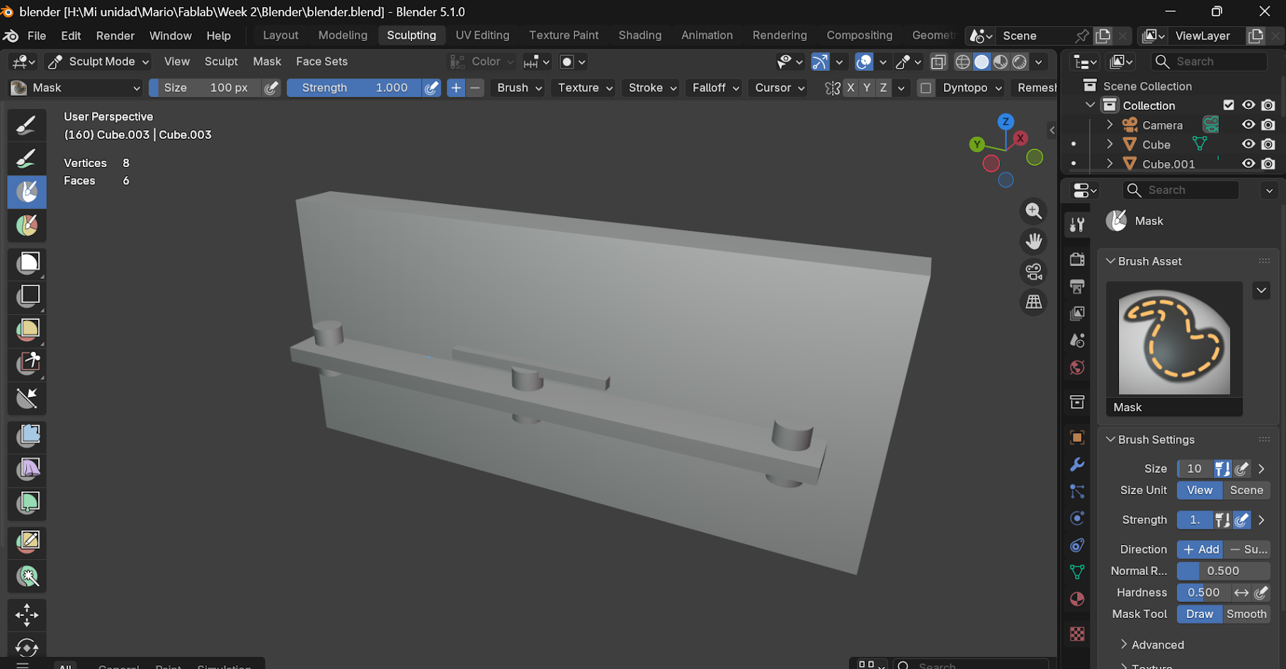
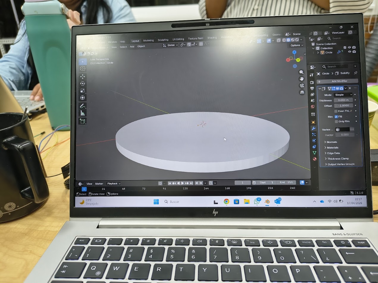
- Blender: CAD model, realistic shot
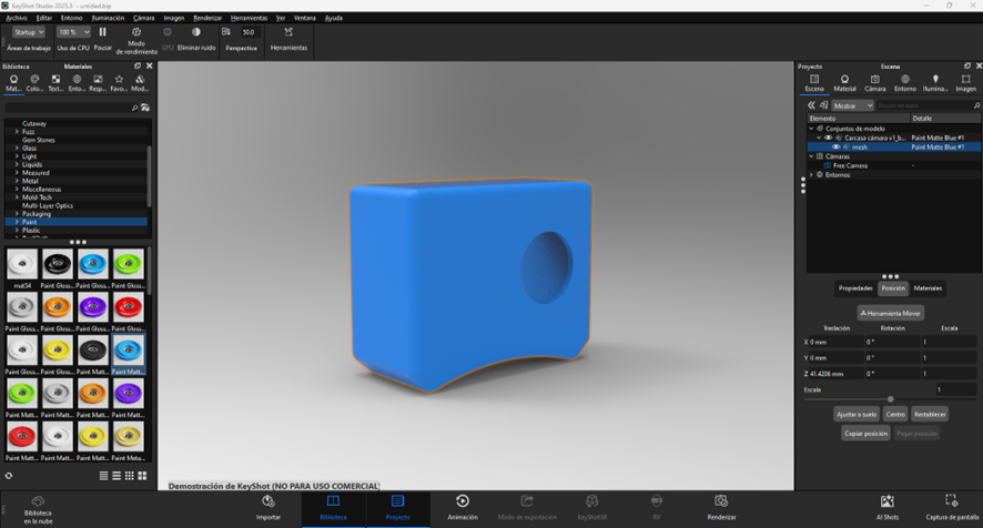
- KeyShot: industrial designers, materials (metal, plastic, glass) and render
4) Software experiences
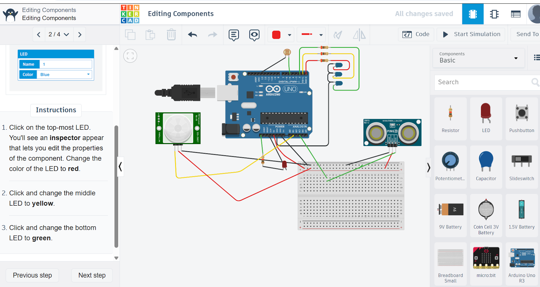
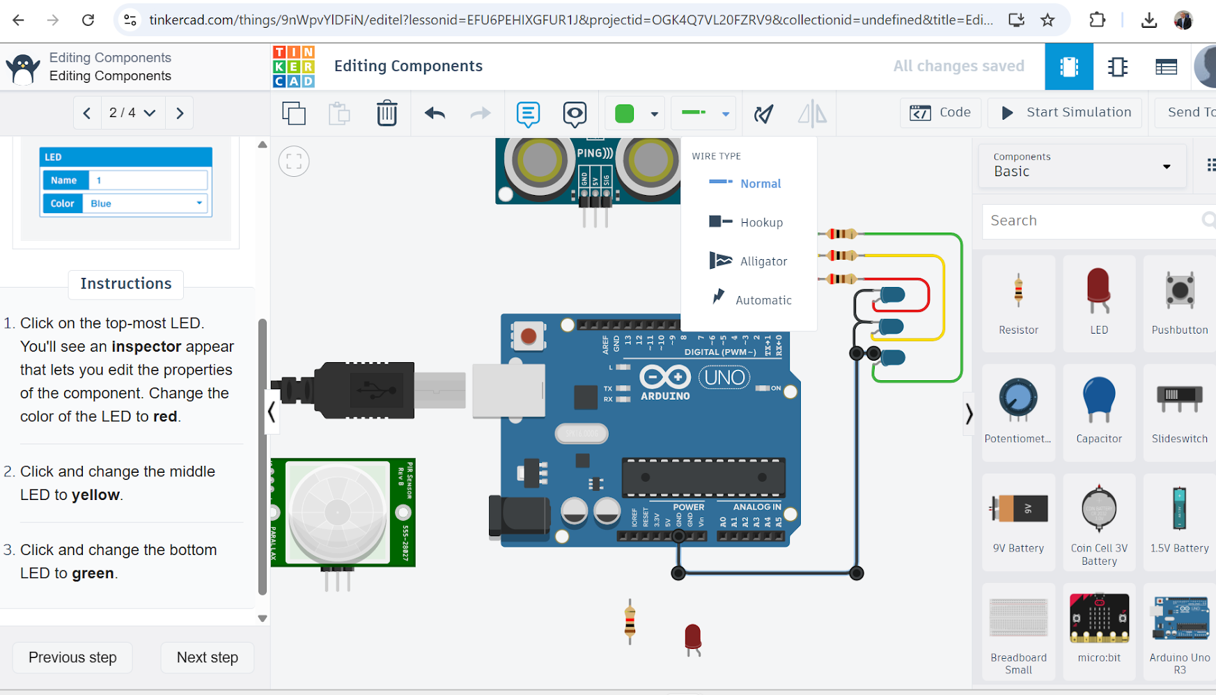
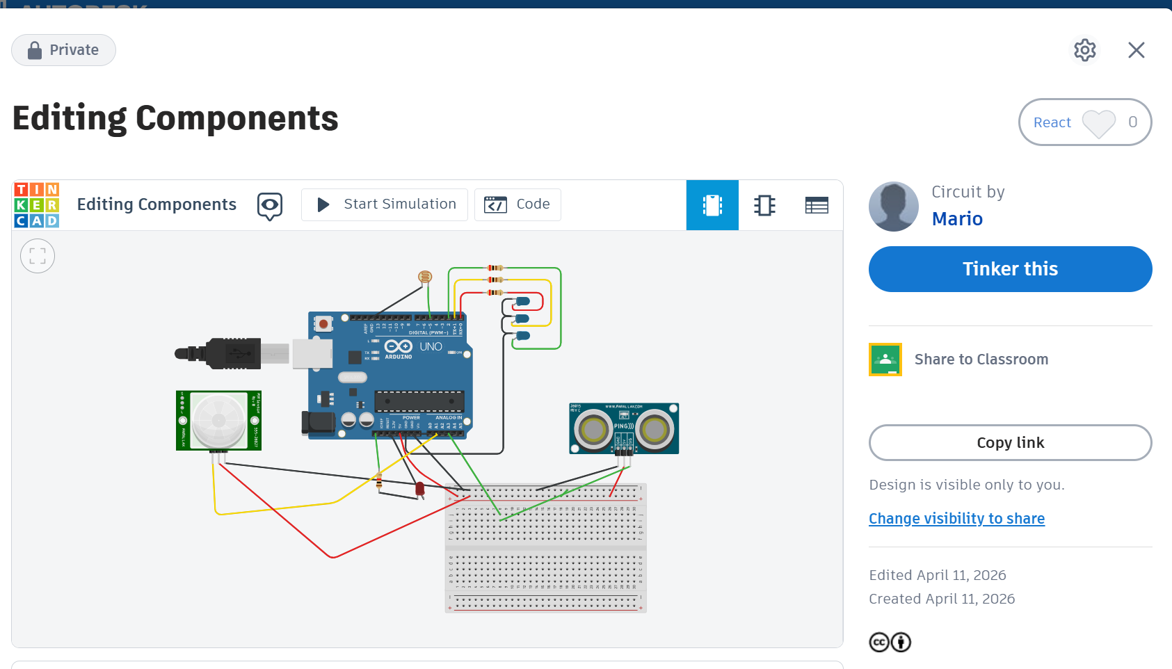
Softwares
- Autodesk suites
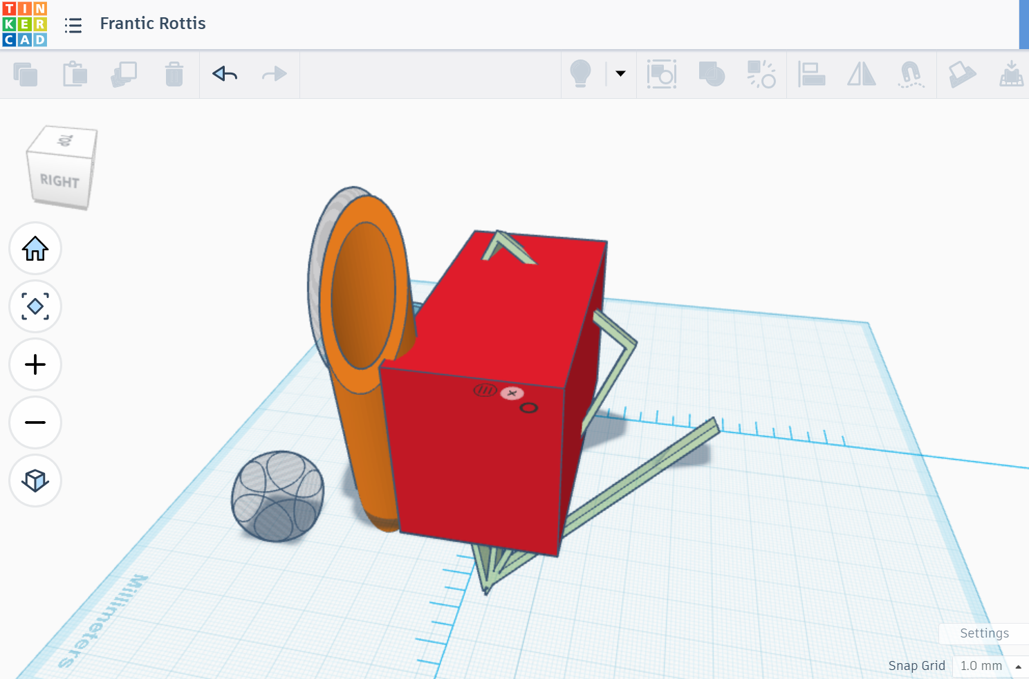
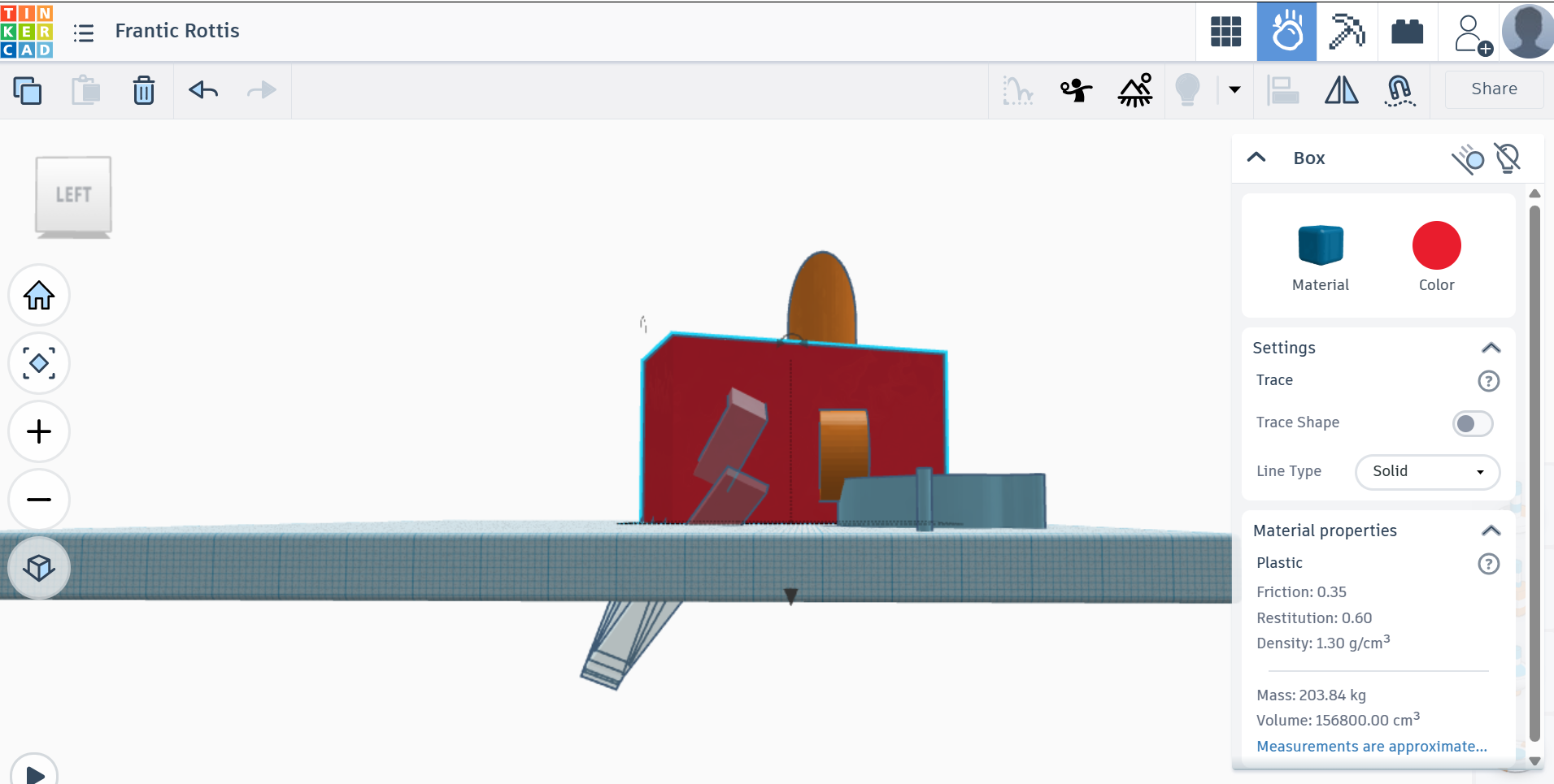
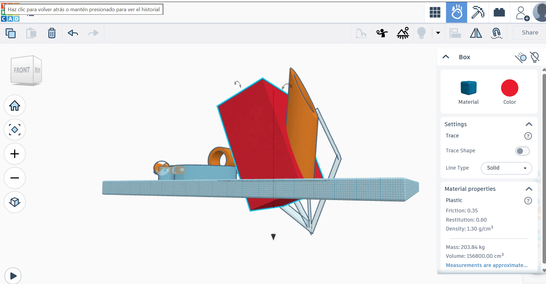
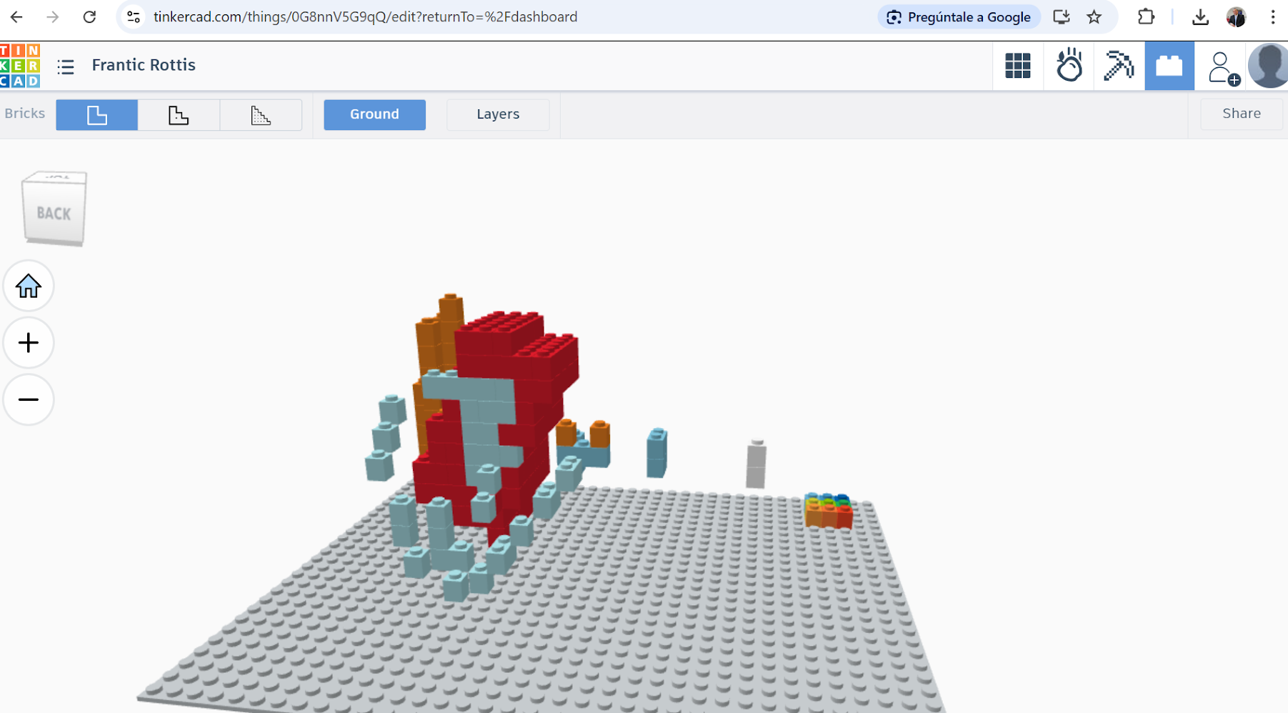
- Thinkercad
- Fusion
- Blended
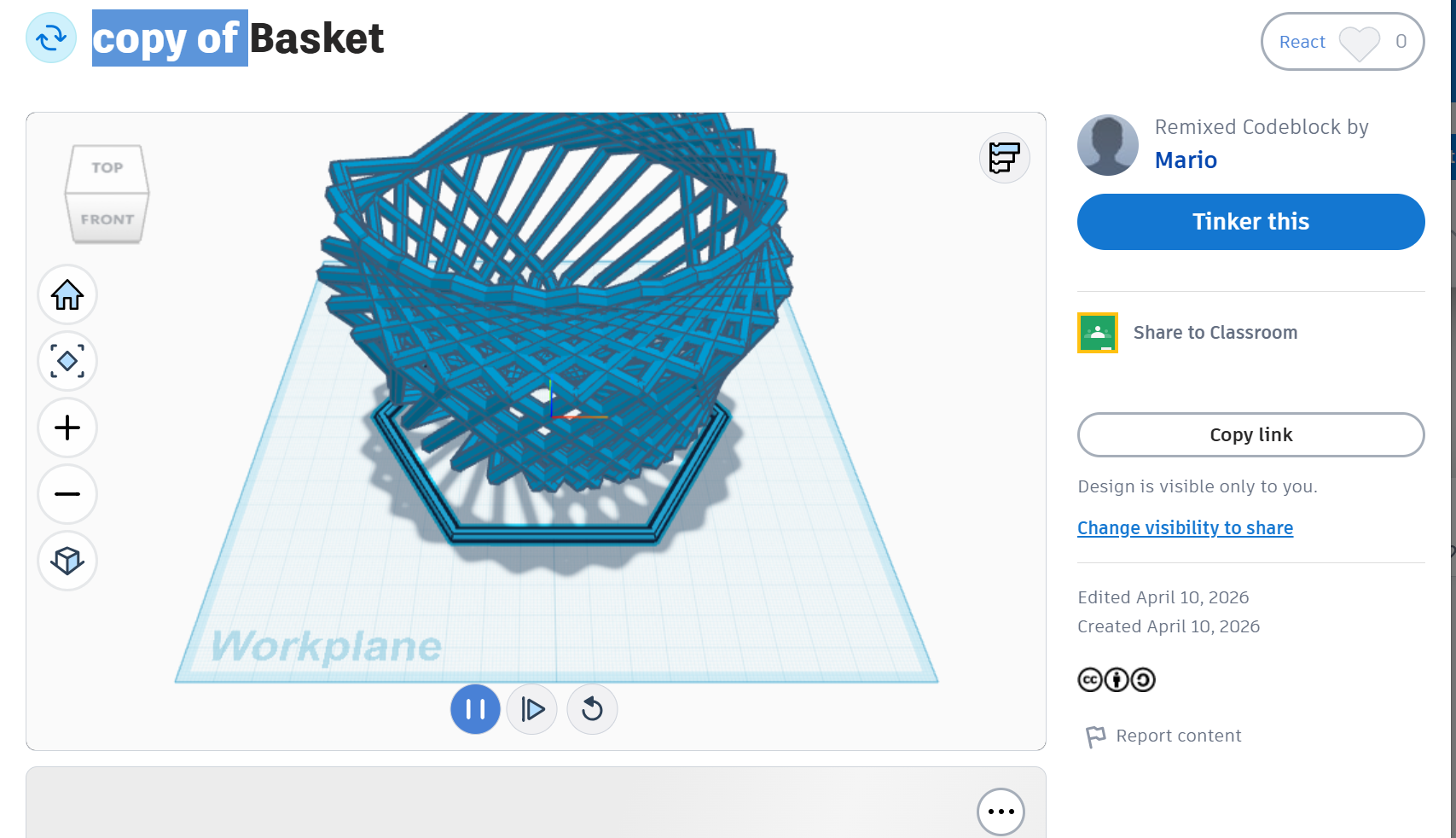
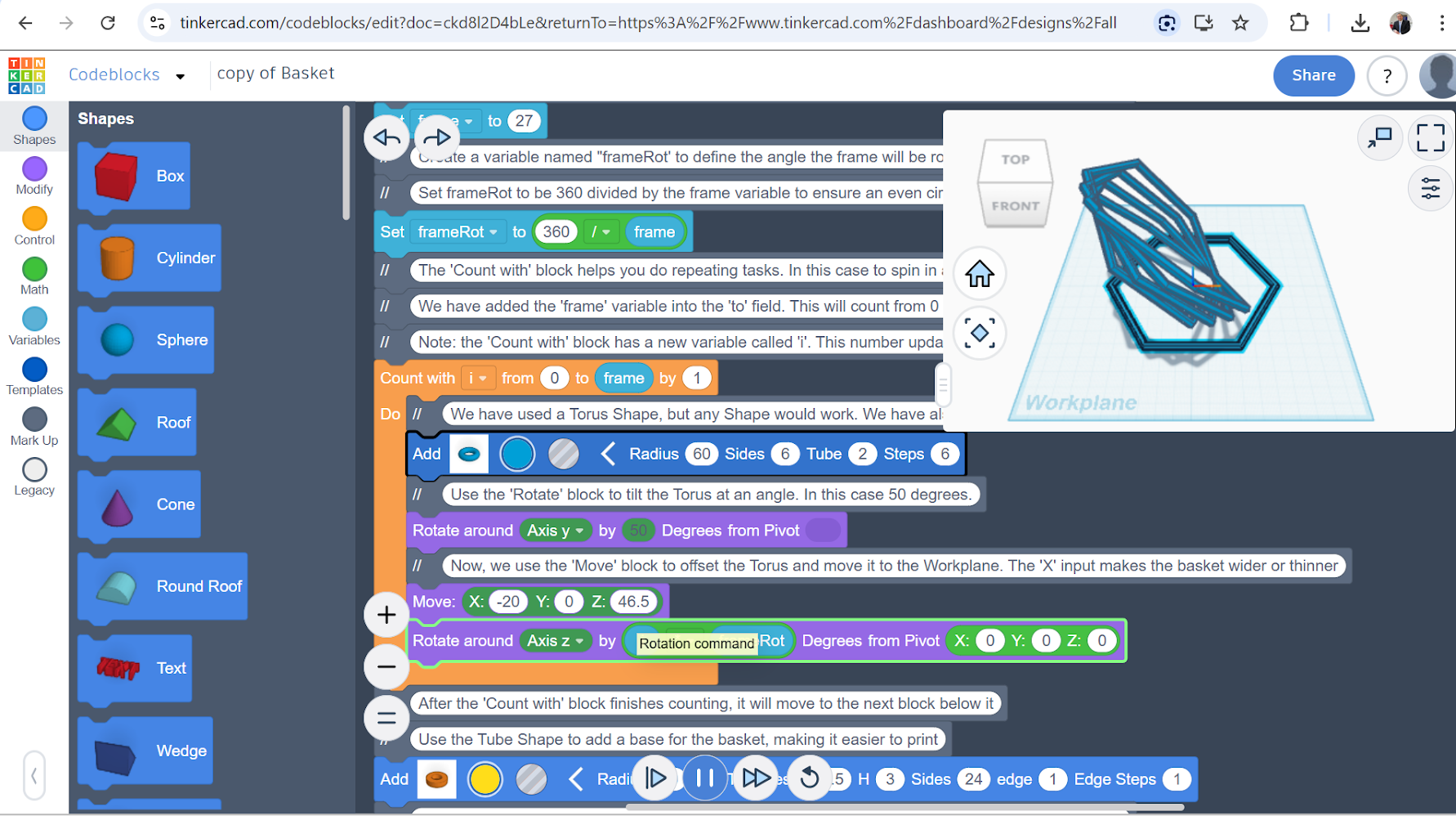
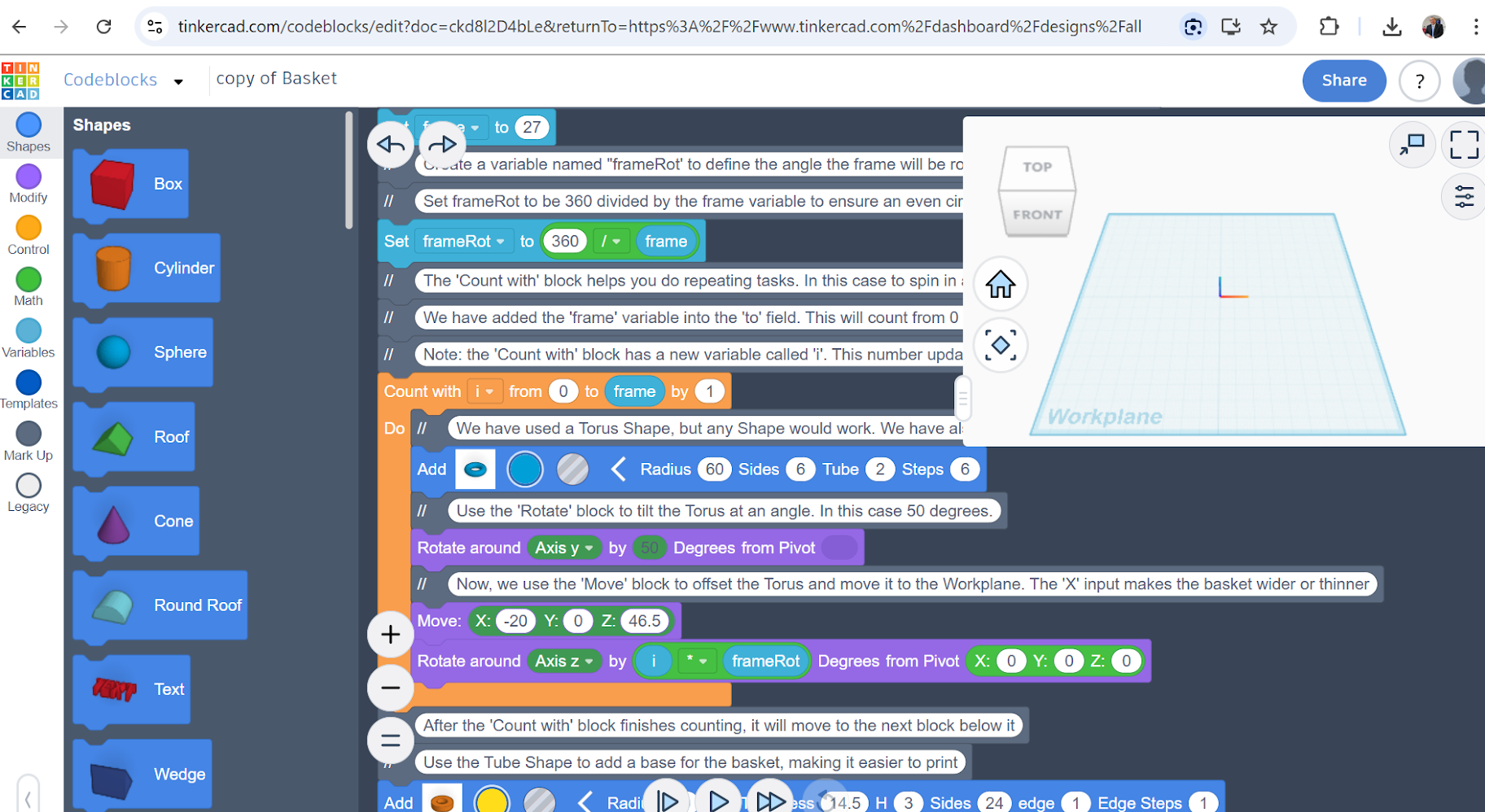
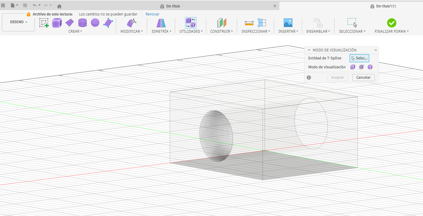
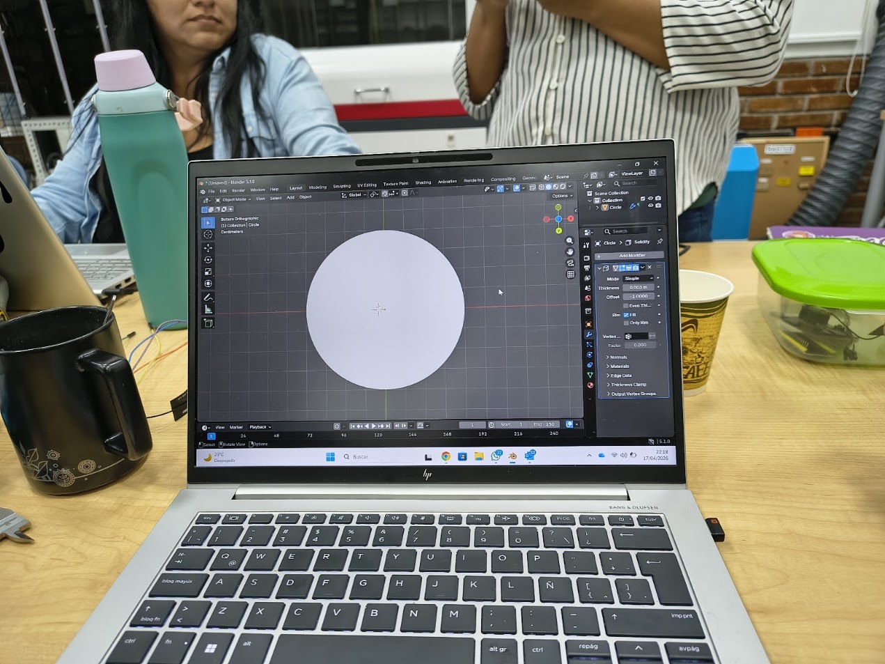
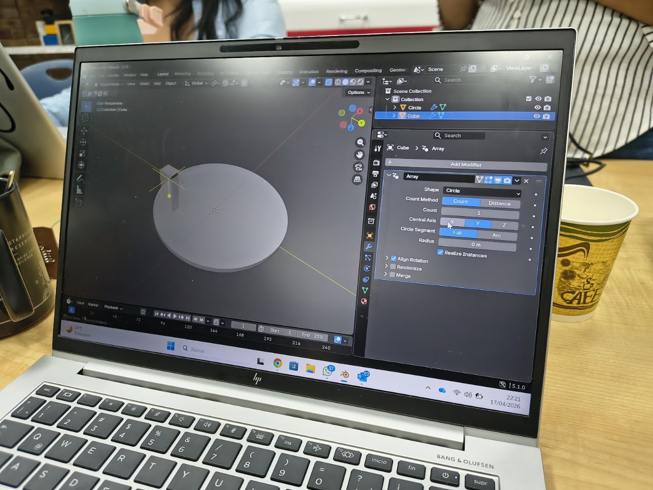
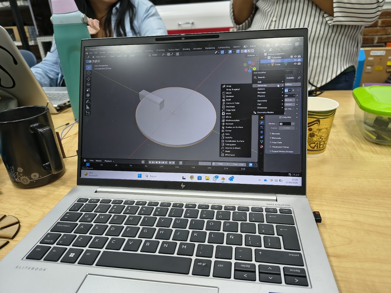
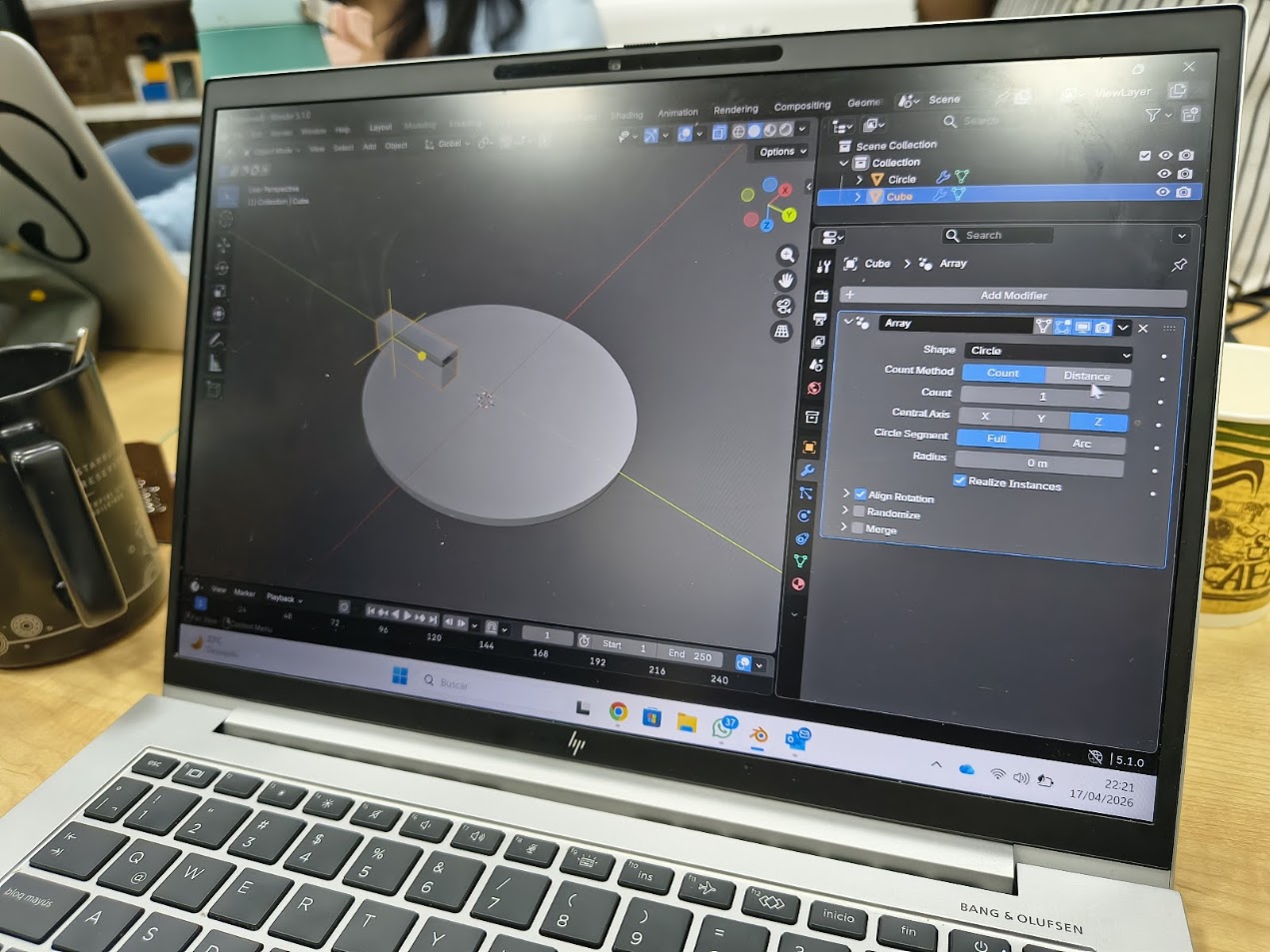
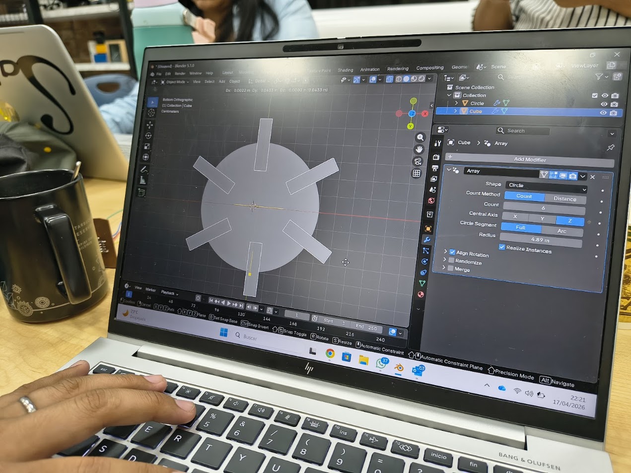
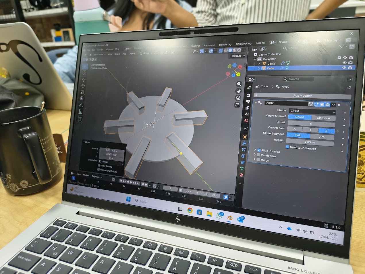
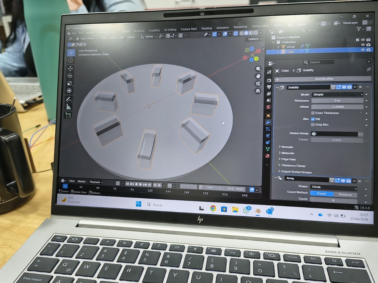
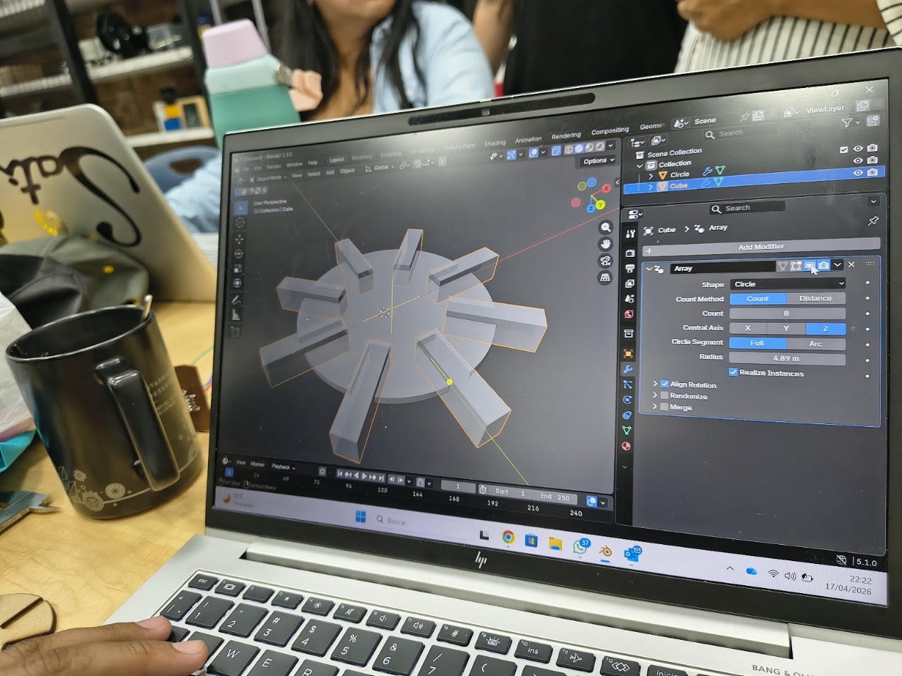
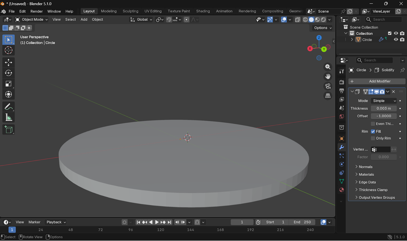
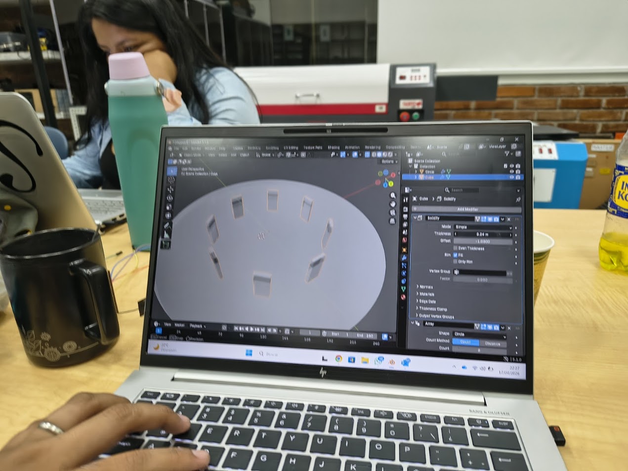
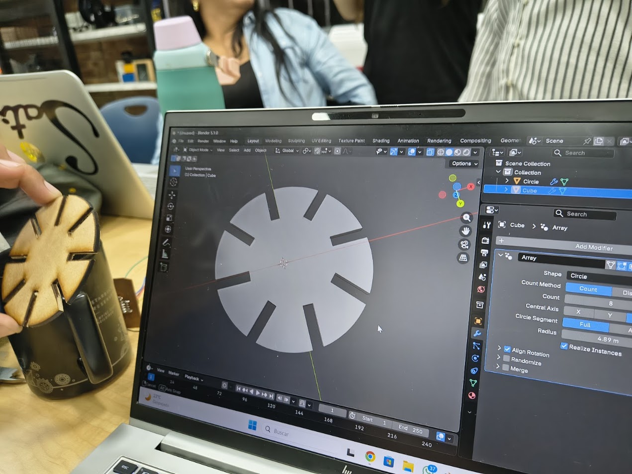
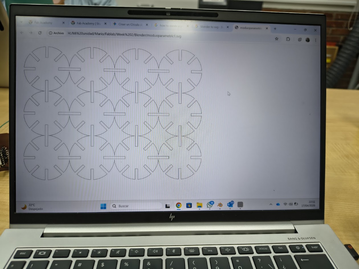
5) A parametric design explanation
What is a parametric design
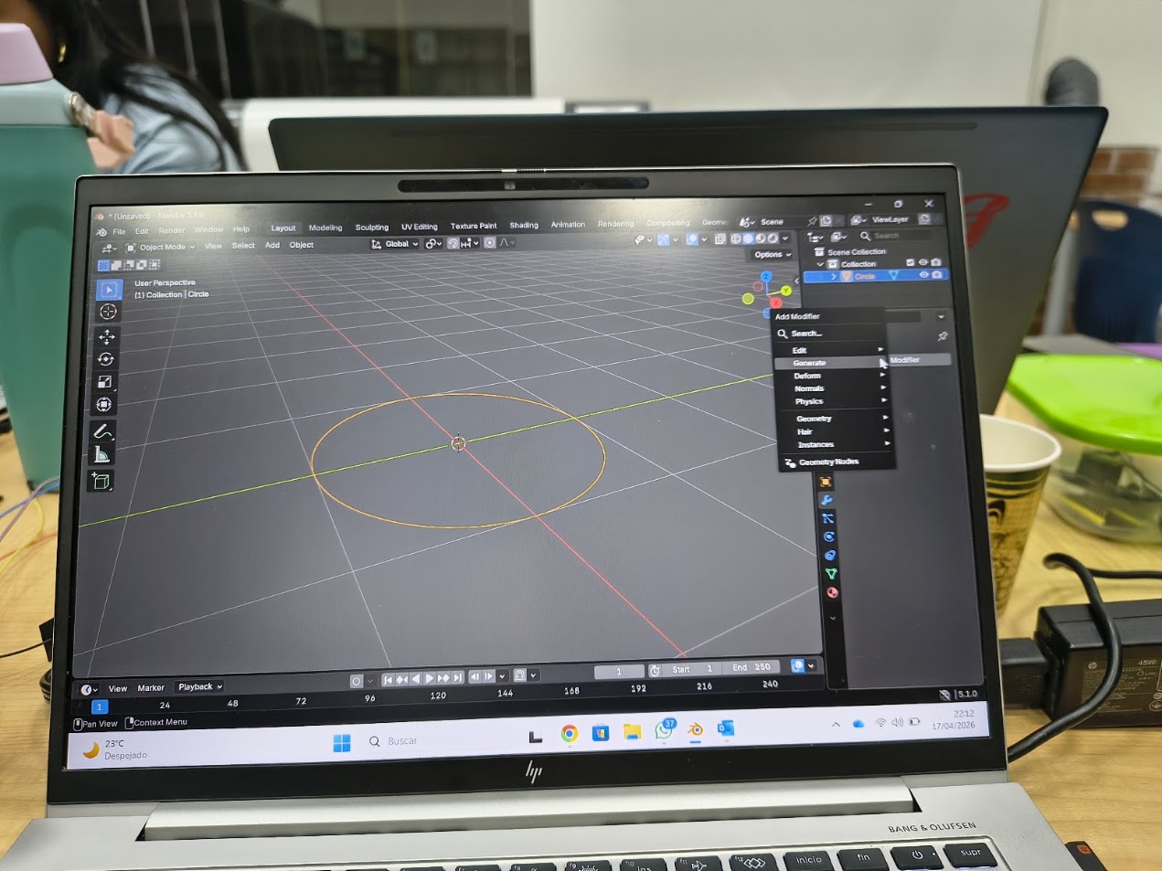
- Design approach using parameters (variables) and rules, instead of drawing a fixed shape
- When you change parameters, the design automatically update
- Useful for fast iterations, easy customization, and control complex geometries
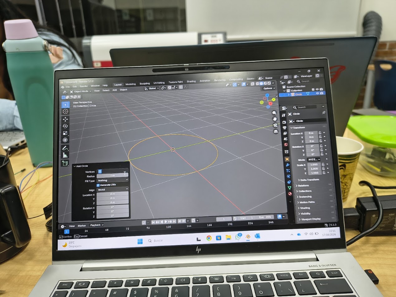
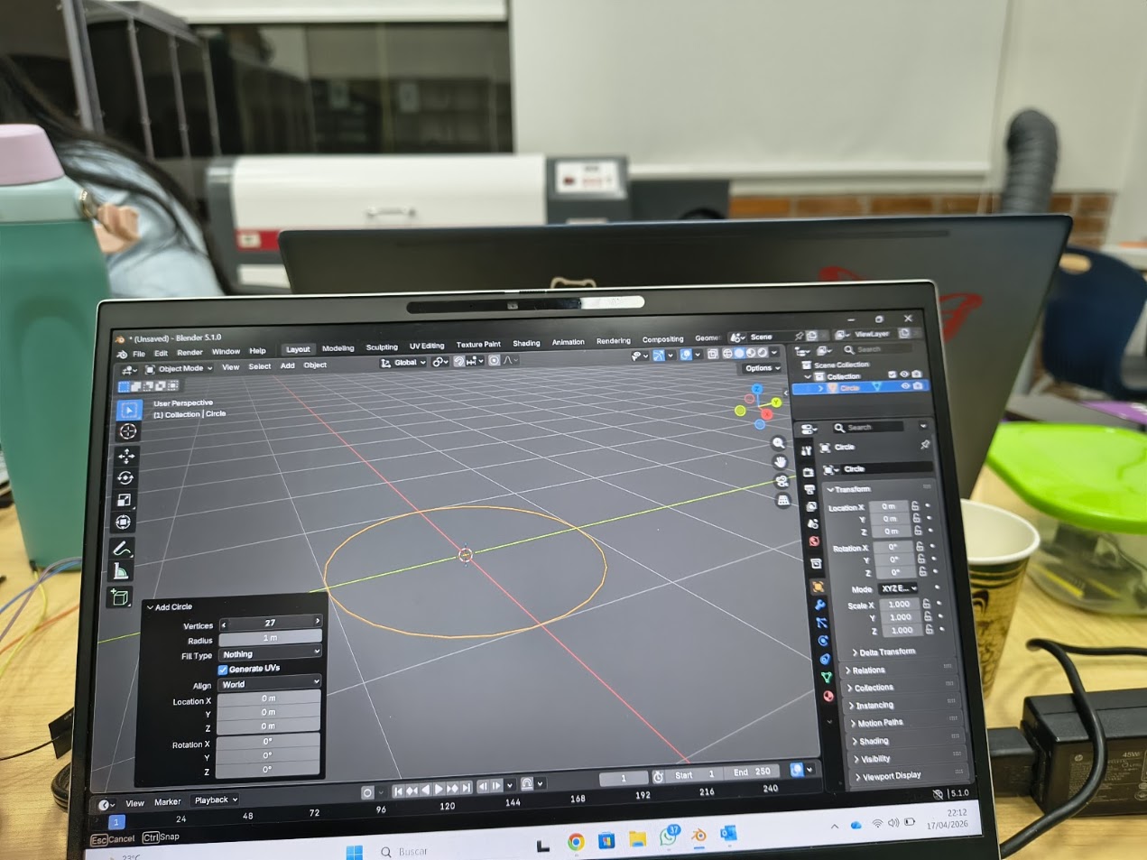
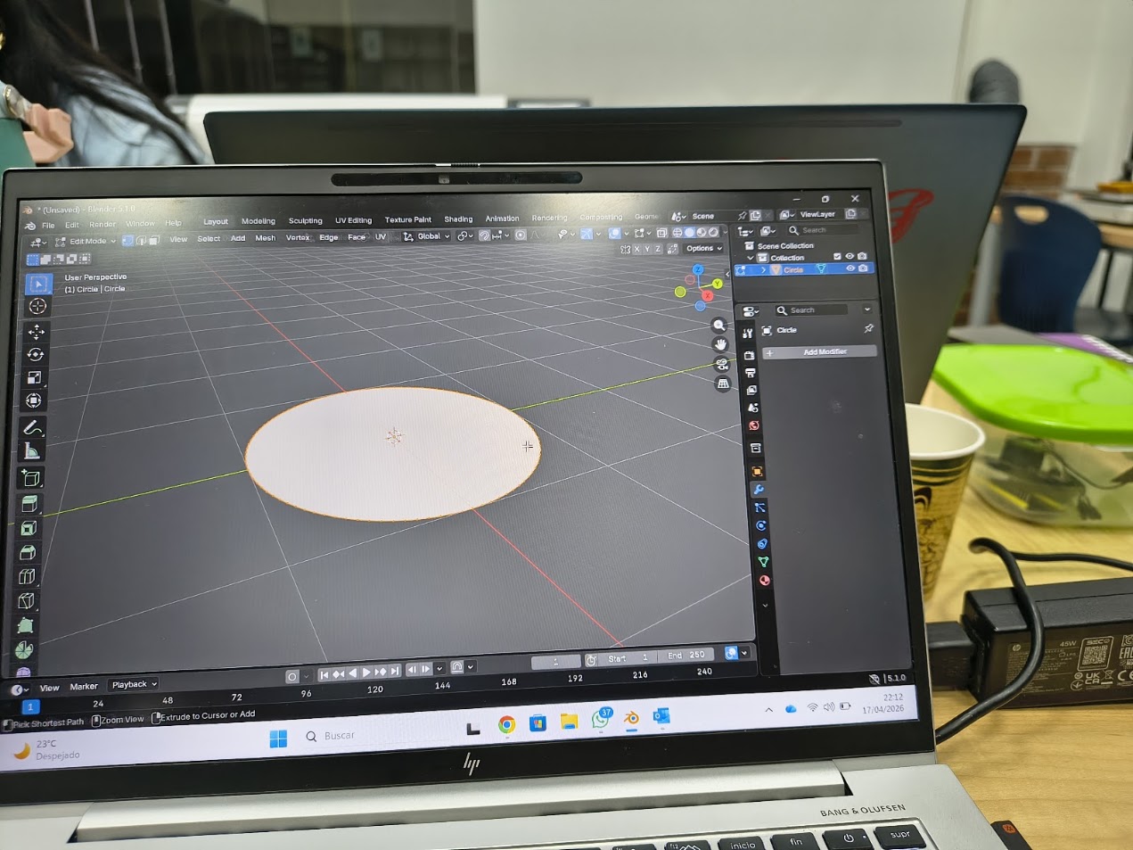
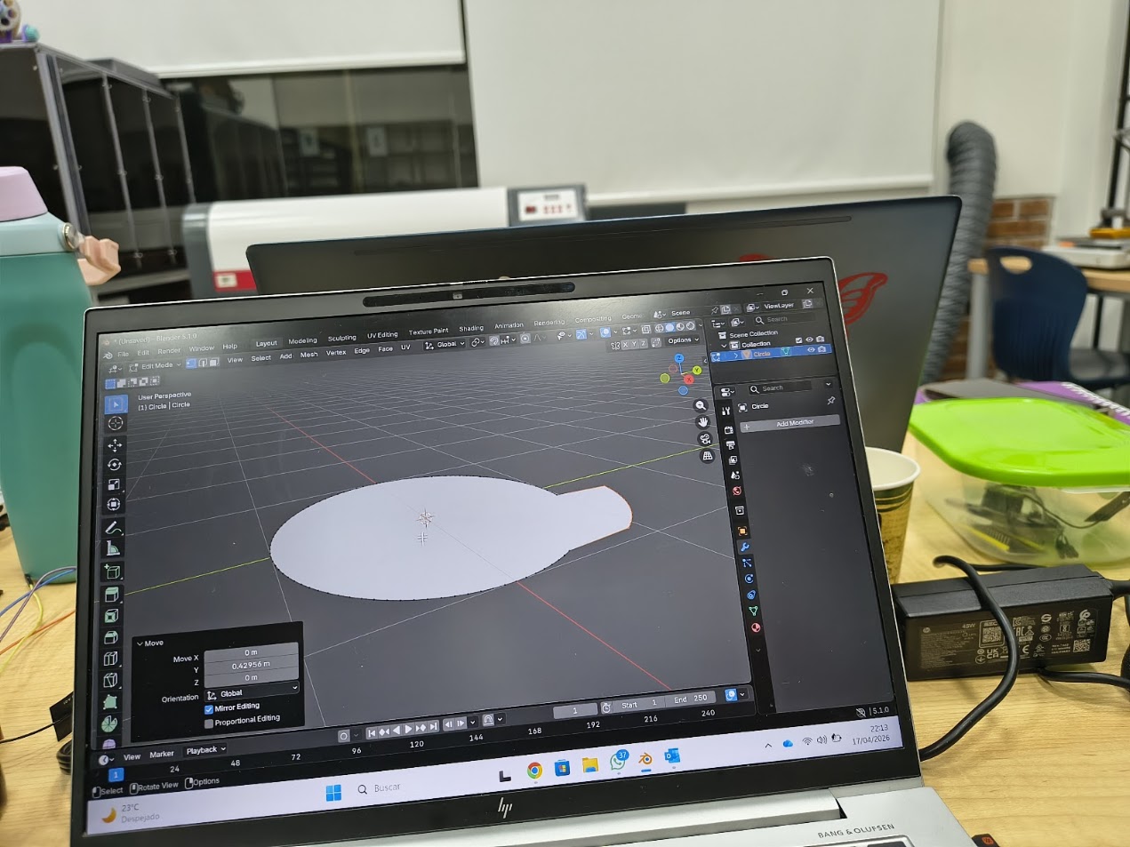
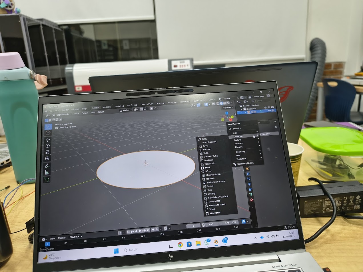
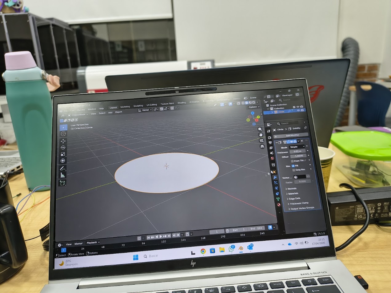
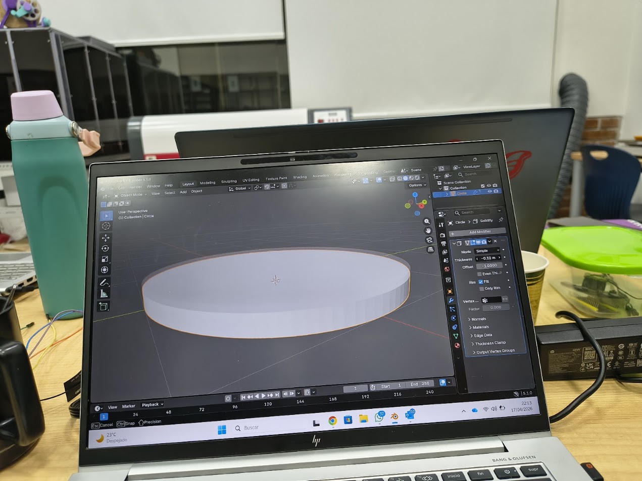
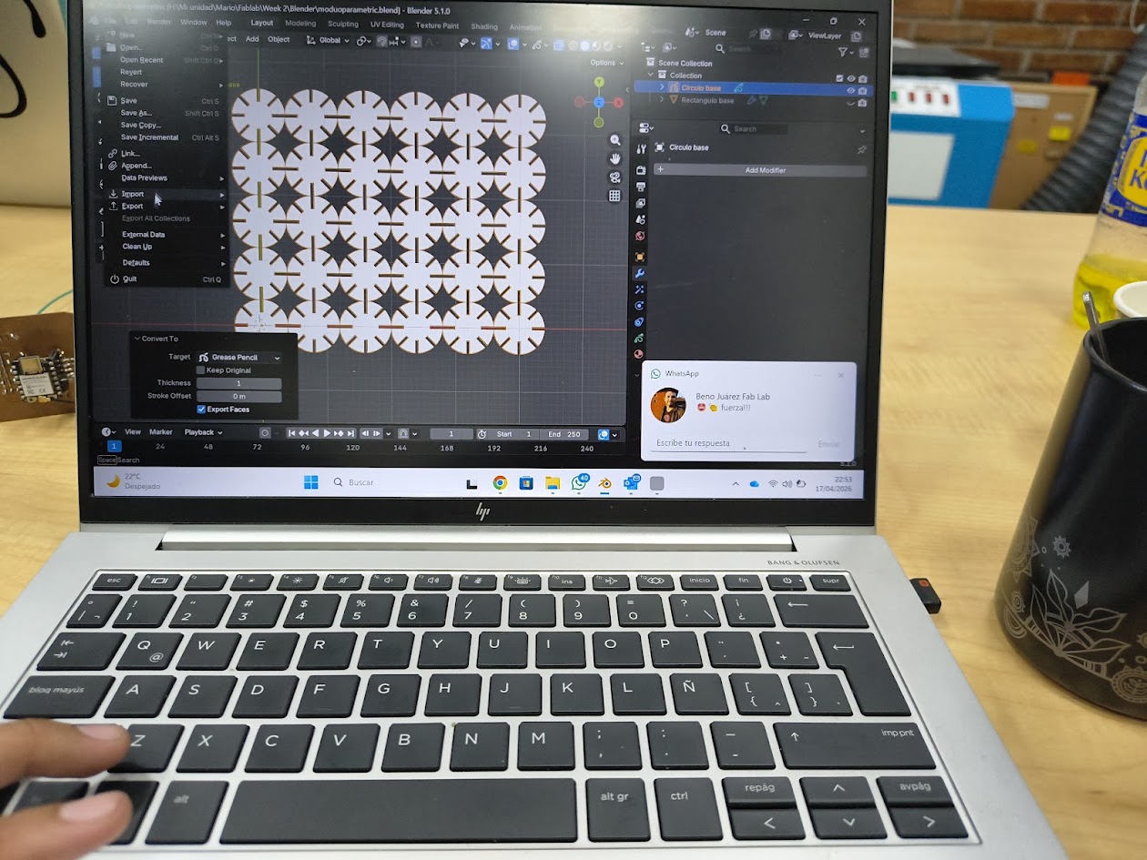
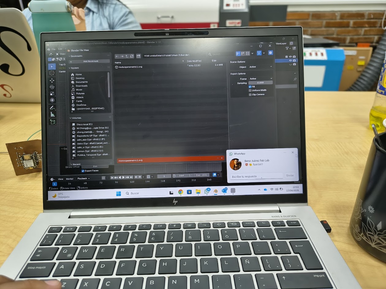
- We used Blended in this example


CAD / 3D Software Comparison
| Feature | Tinkercad | Fusion 360 | Blender | Rhino |
|---|---|---|---|---|
| Type | Basic CAD | Advanced CAD/CAM/CAE | 3D Modeling & Animation | NURBS CAD |
| Best For | Beginners | Engineering Design | Art & Animation | Industrial Design |
| Ease of Use | Very Easy | Moderate | Difficult | Moderate |
| Modeling | Drag & Drop | Parametric | Mesh / Sculpting | NURBS |
| Precision | Low | Very High | Low | Very High |
| Rendering | ❌ | ✅ | ✅ Advanced | ✅ |
| Simulation | ❌ | ✅ | ❌ | ⚠️ Limited |
| Animation | ❌ | ⚠️ Basic | ✅ Advanced | ⚠️ Limited |
| Manufacturing | ❌ | ✅ Integrated | ❌ | ⚠️ Plugins |
| Key Difference | Simple & beginner-friendly | All-in-one engineering platform | Creative & visual focus | Precision surface modeling |
| When to Choose | Learning, simple 3D prints | Functional parts, CNC workflows | Rendering, animation, assets | Complex shapes, architecture |
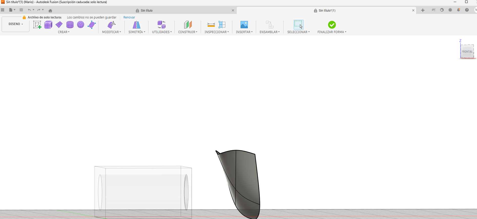
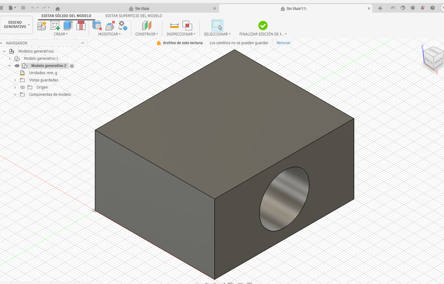
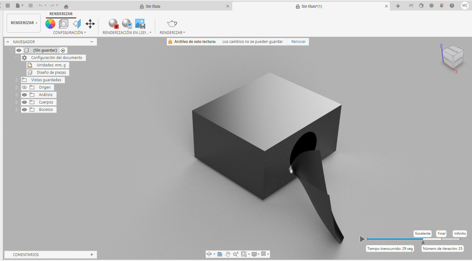
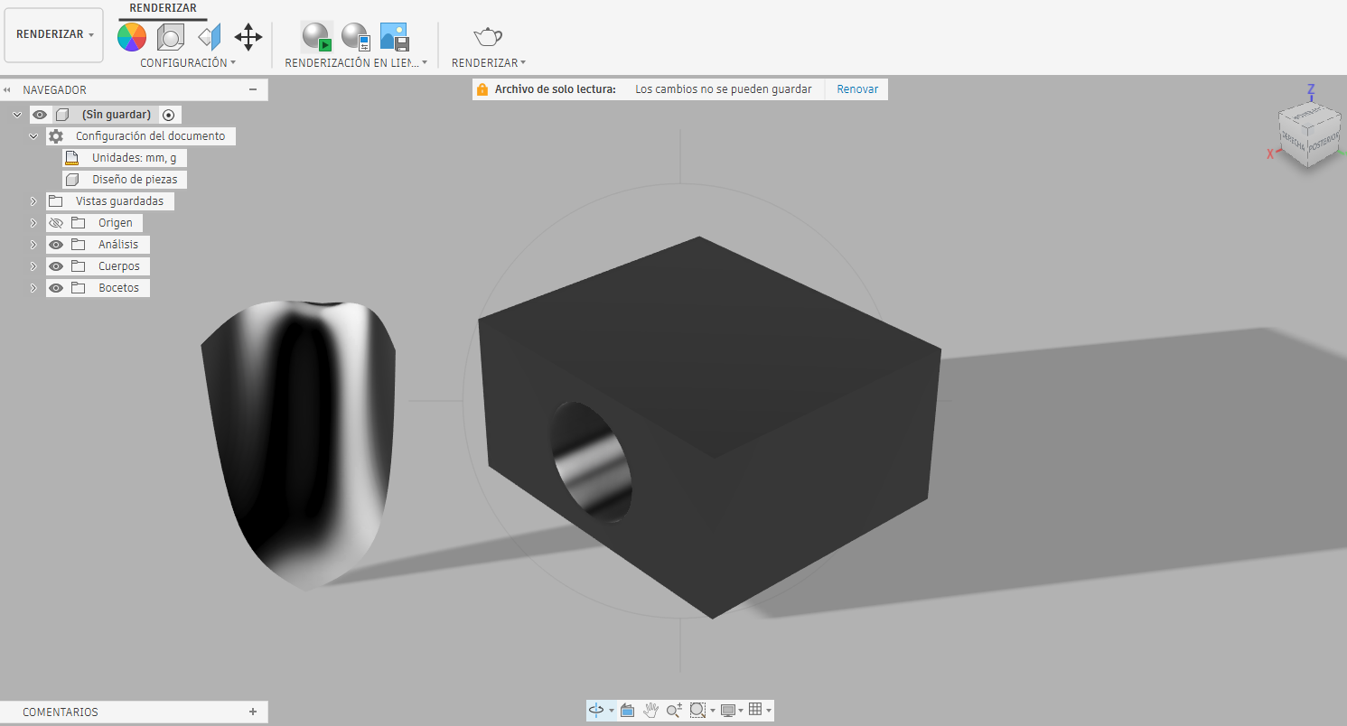
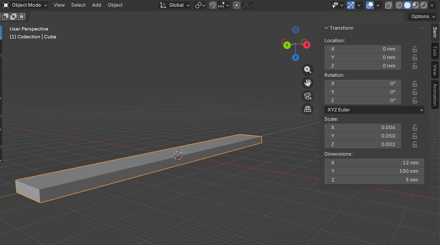
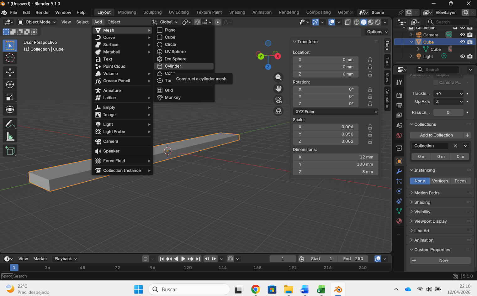
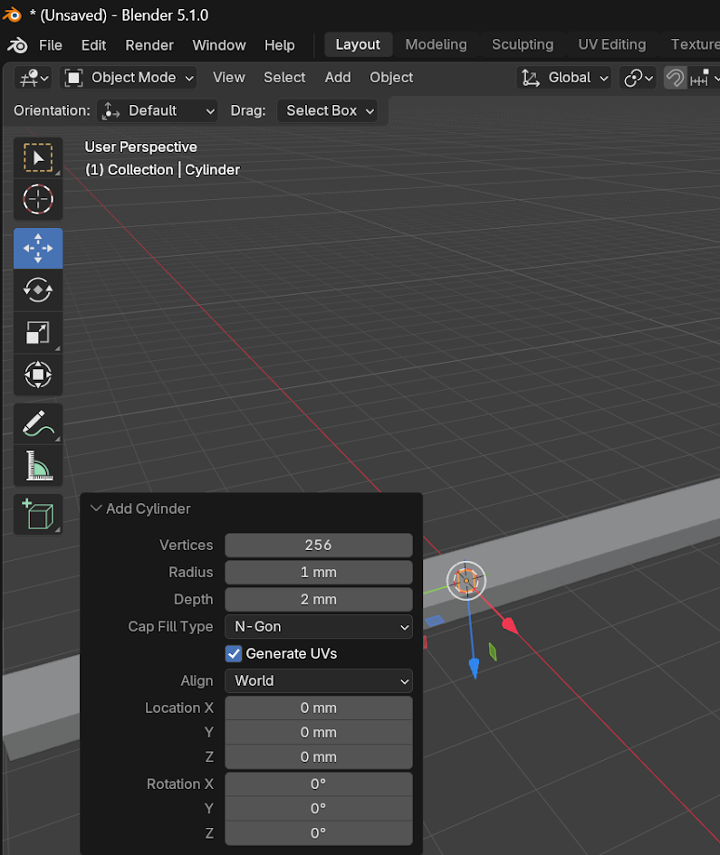
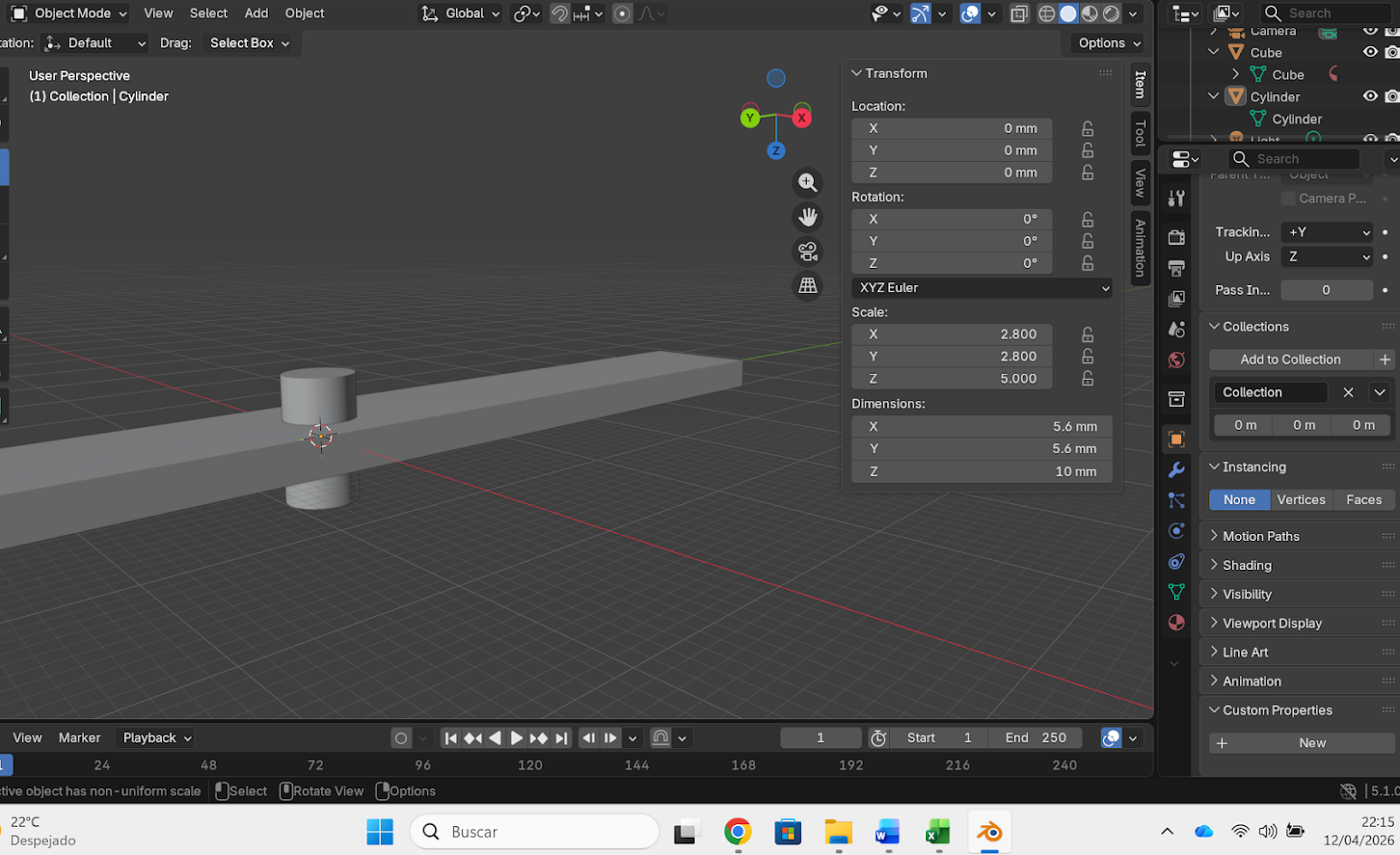
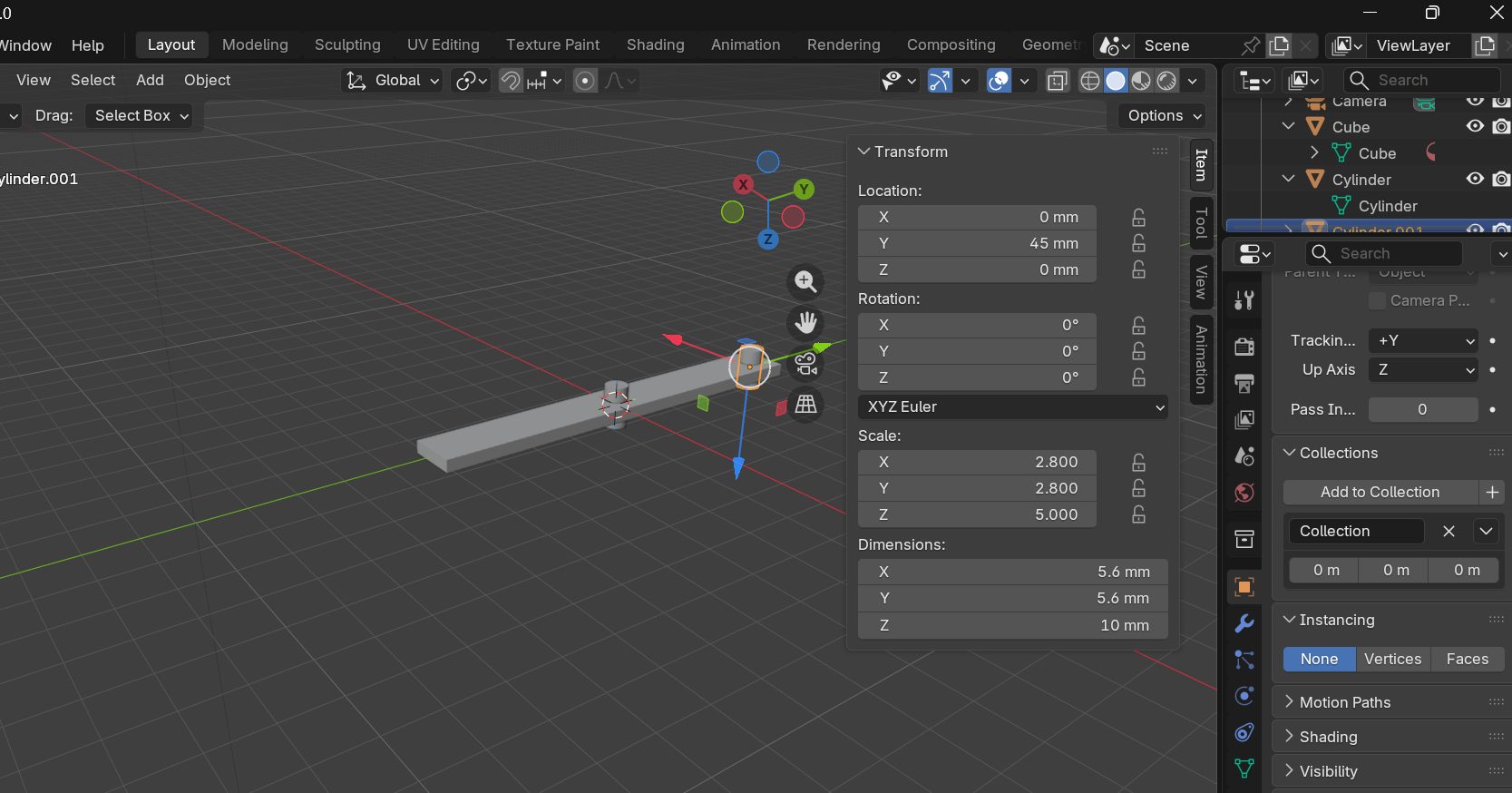
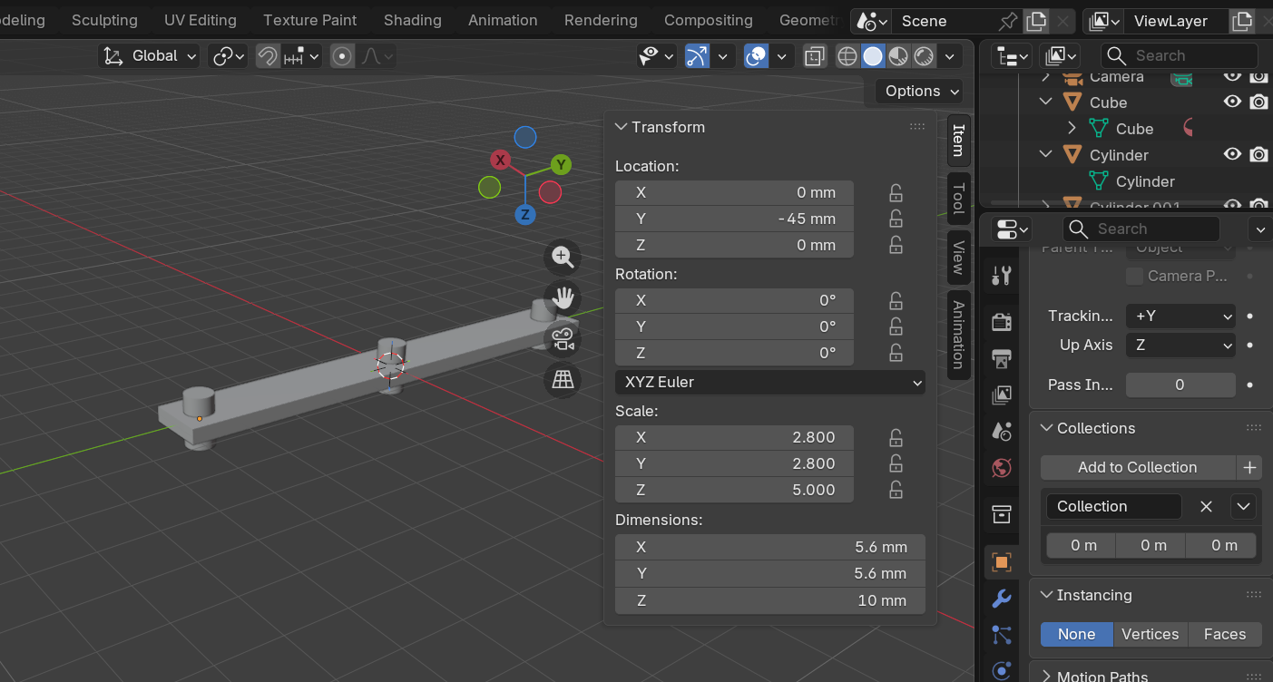
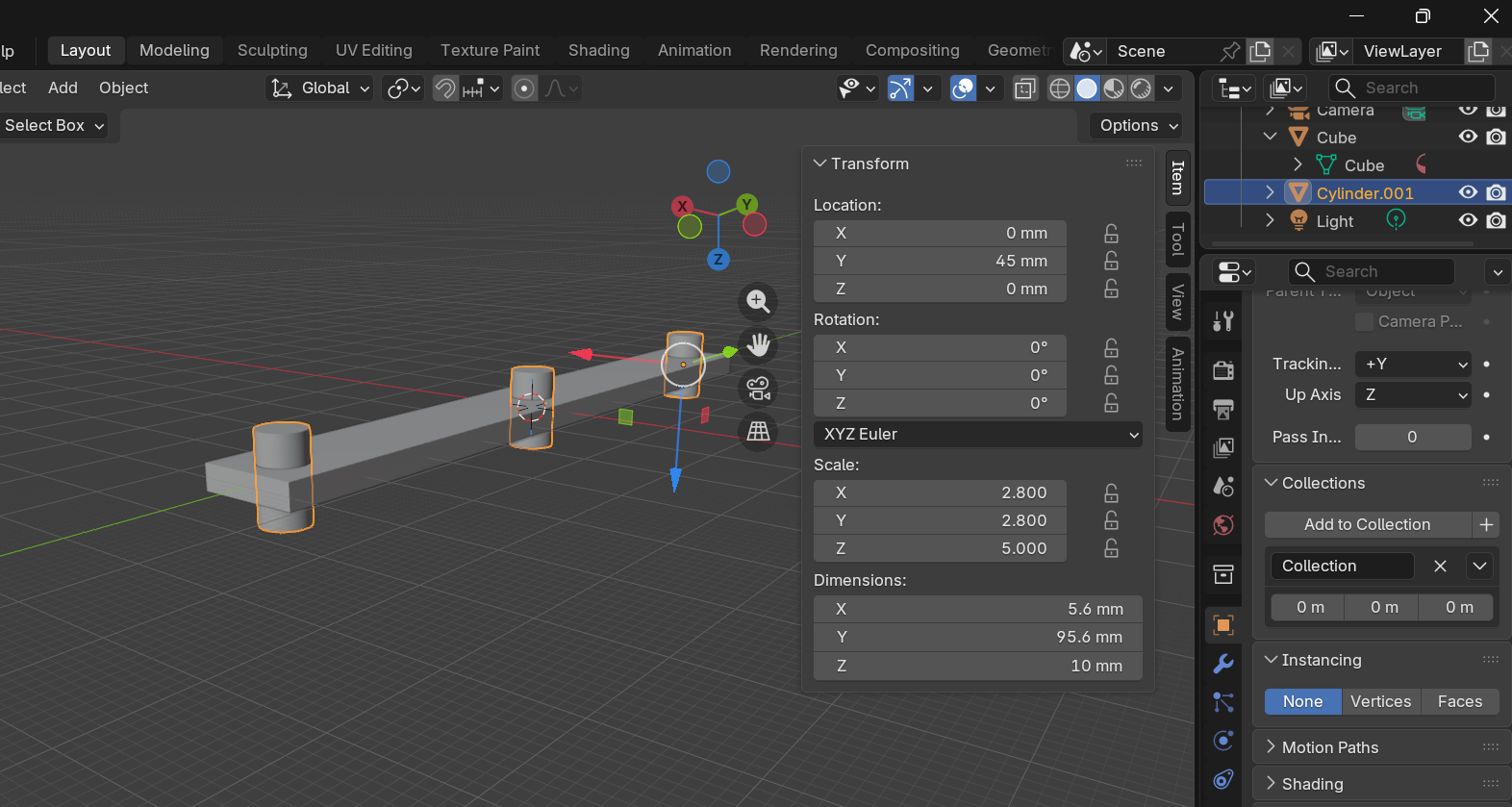
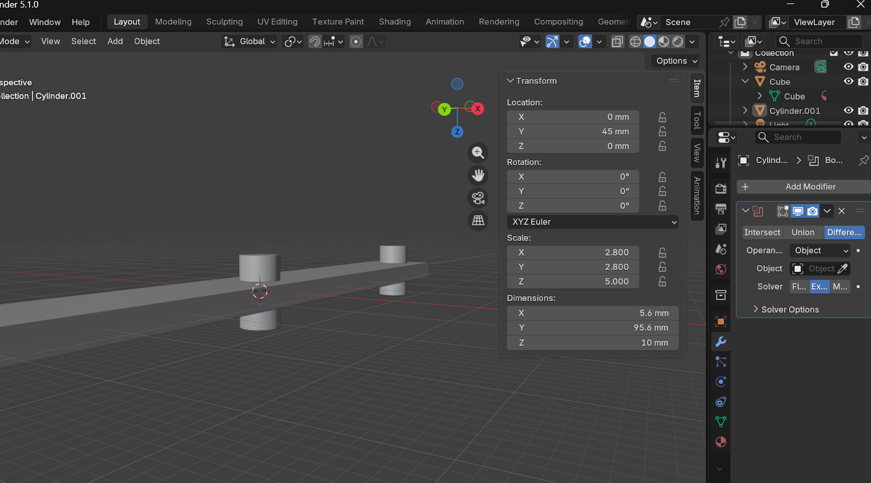
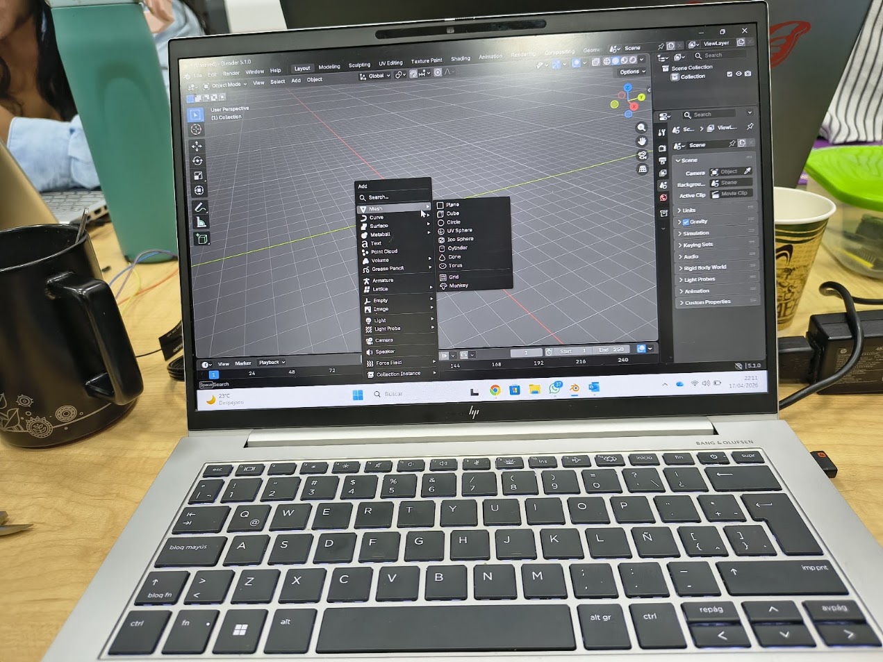
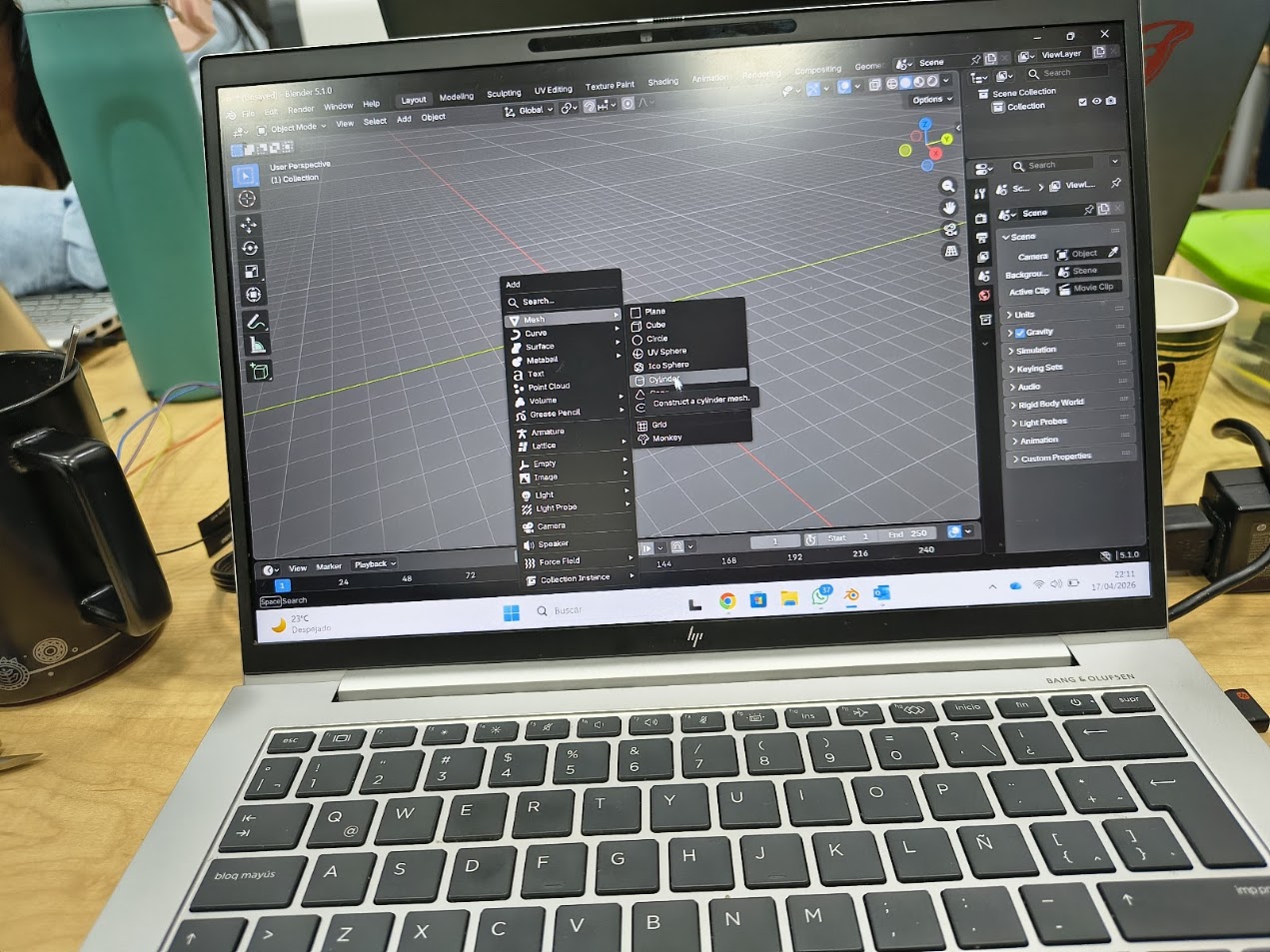
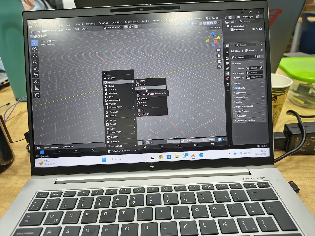
6) Project sketch
Define the 3D software
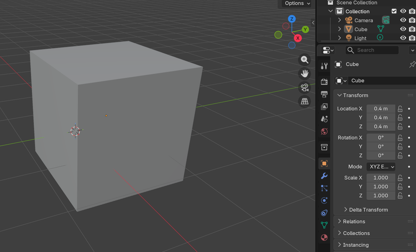
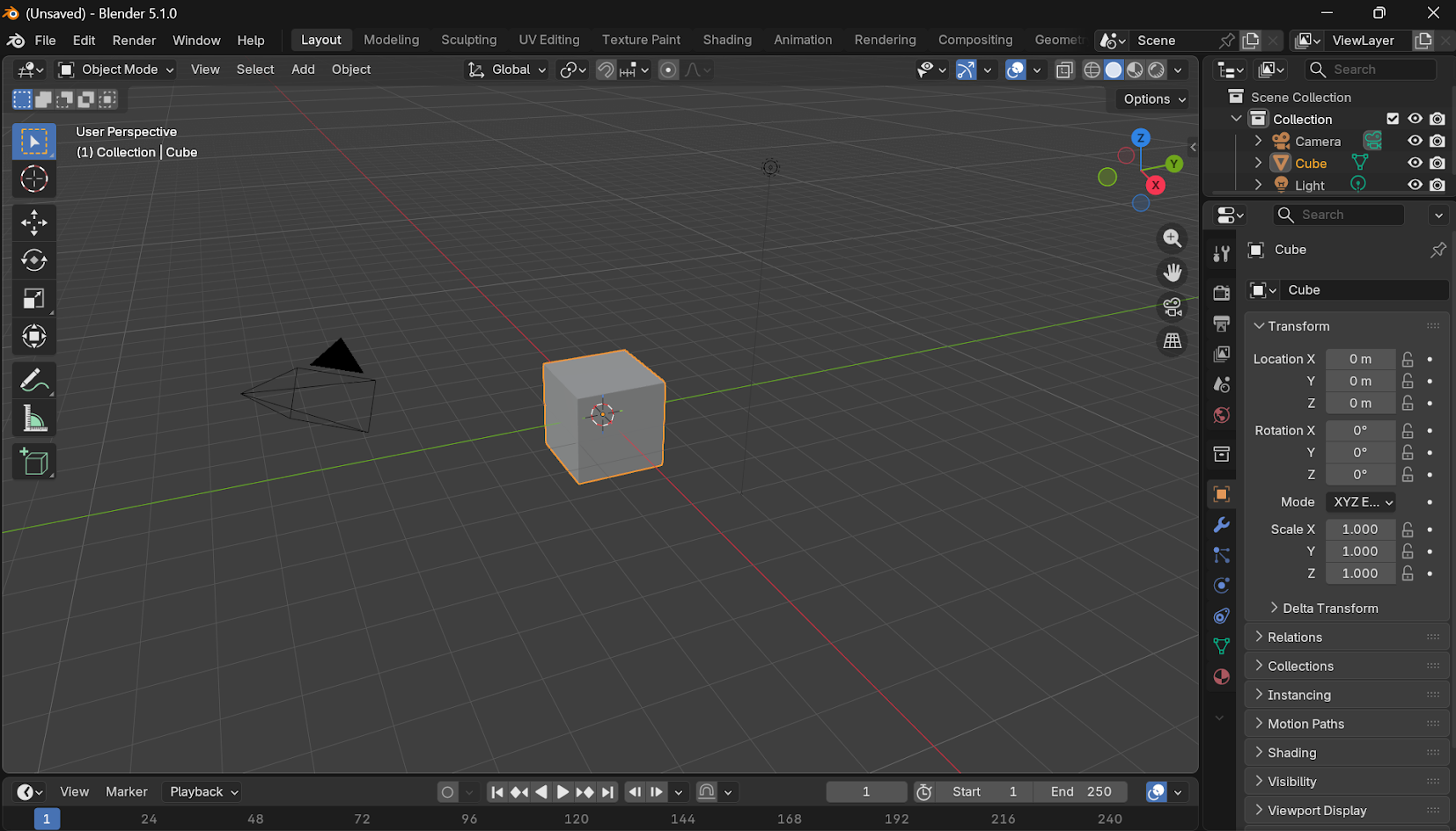
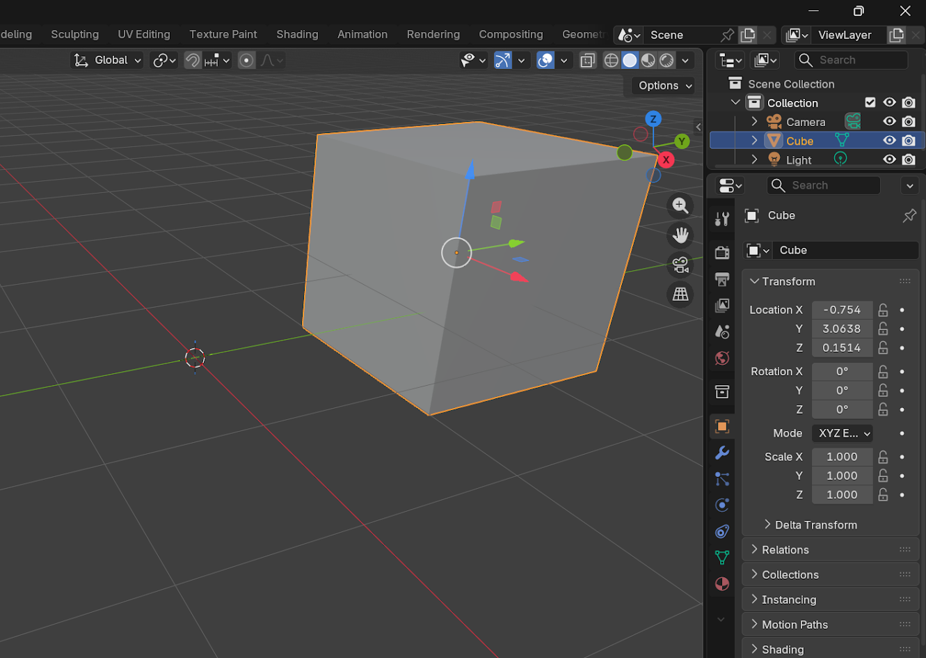
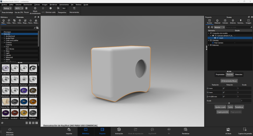
Modelling the camera
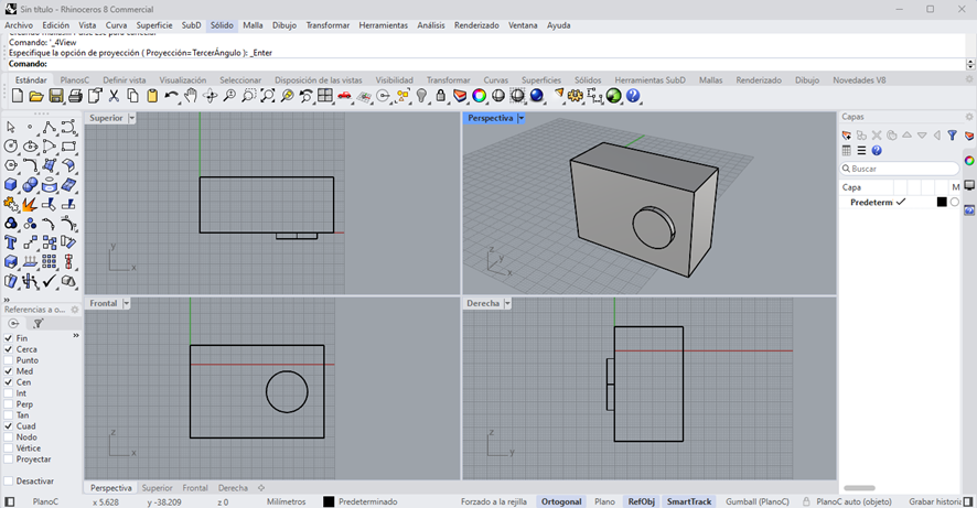
Define a head anthropometry
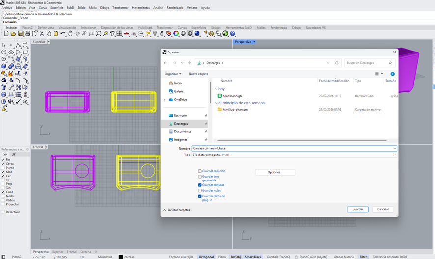
Export model to Rhinoceros
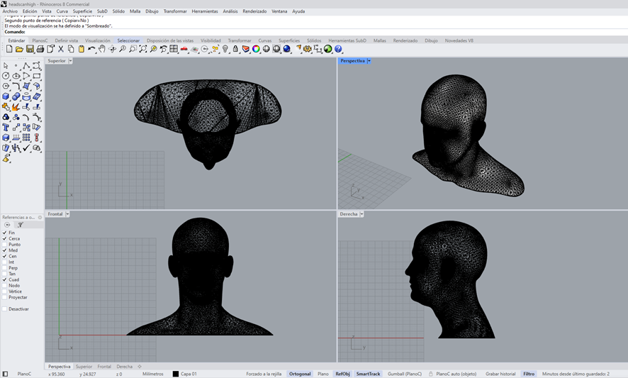
Sketching the project
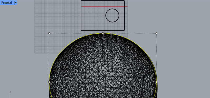
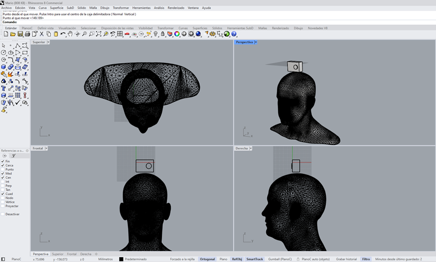
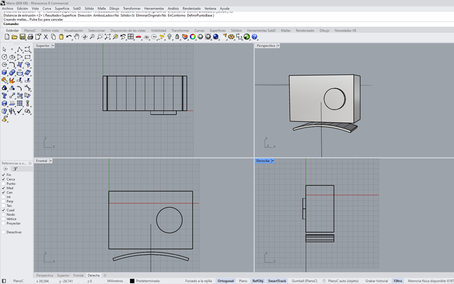
Defining the camera
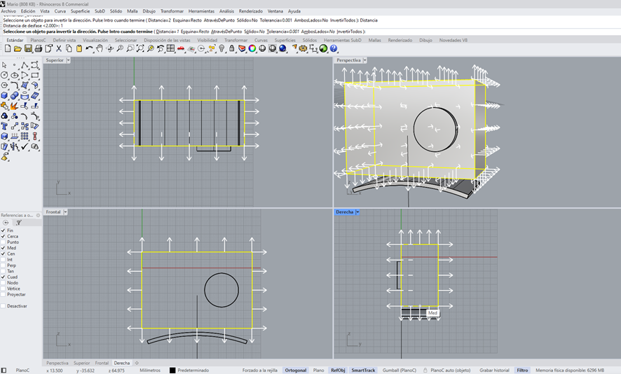
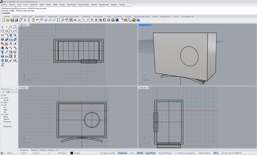
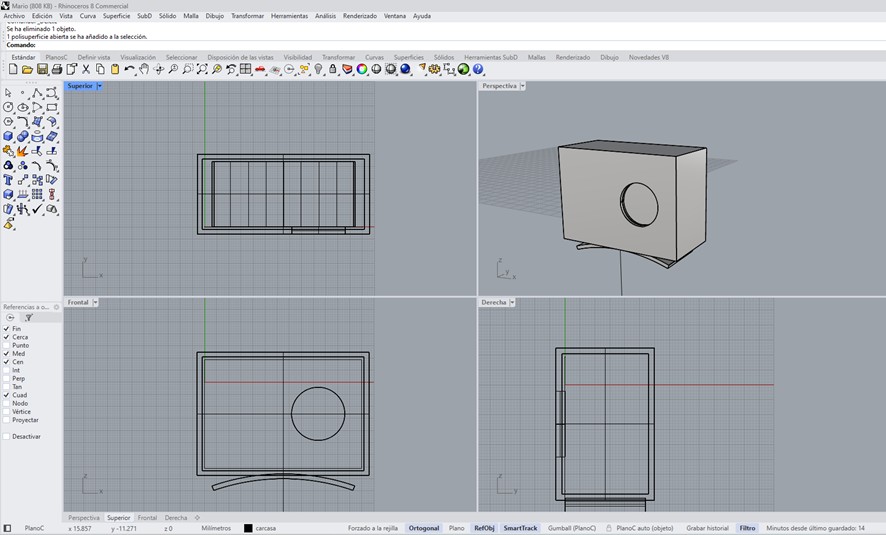
Defining the camera
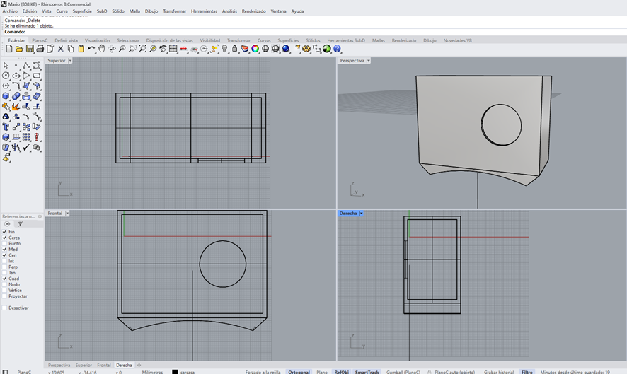
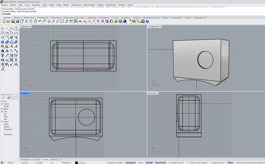
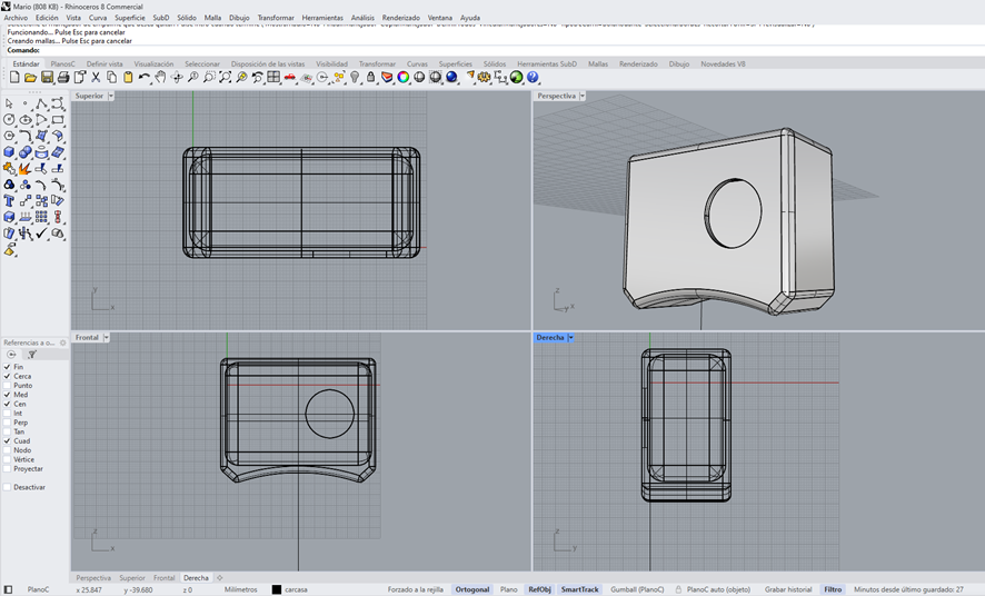
Defining the camera
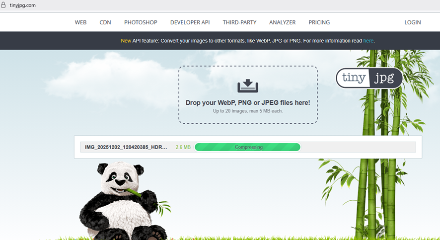
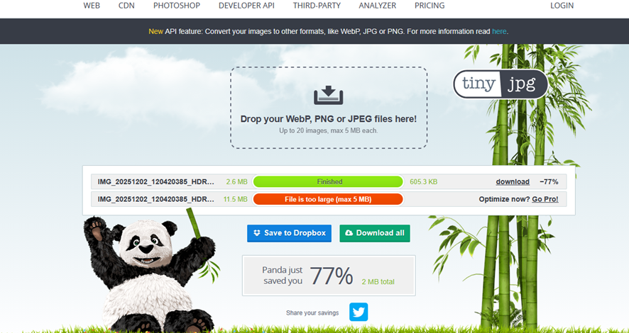
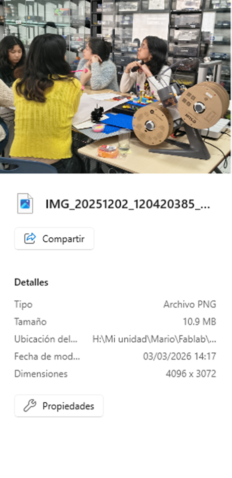
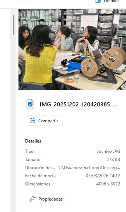
7) Image and video compression
a) Image
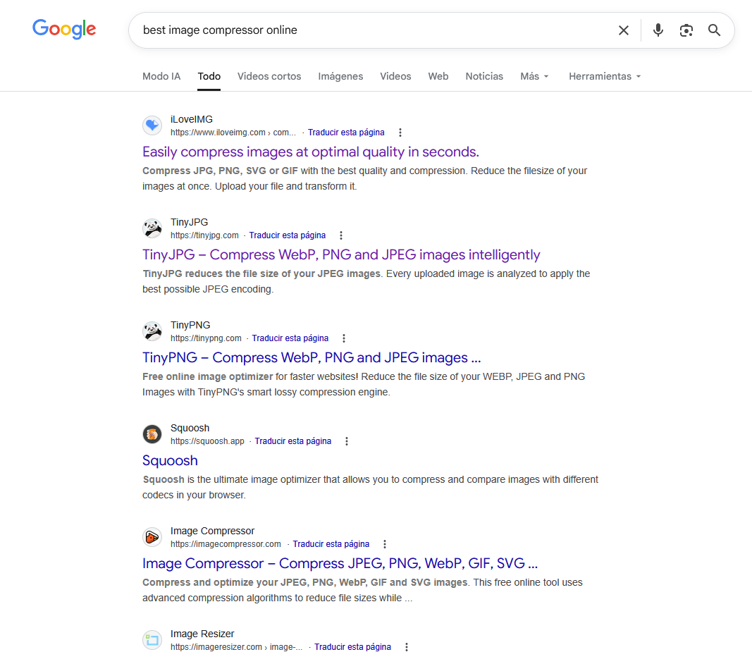
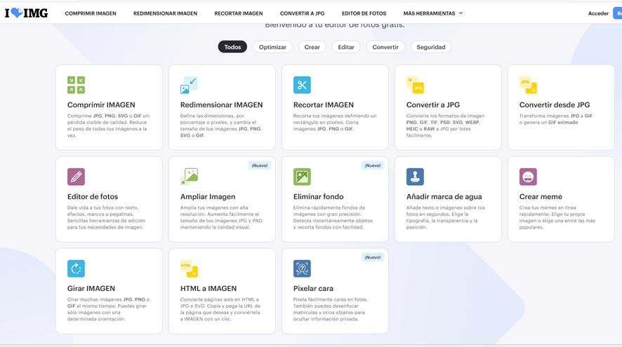
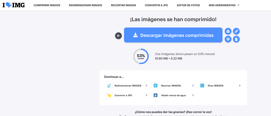
- A lot of tools
- We used ILoveIMG, TinyJPG
- One option is save with other format
b) Video
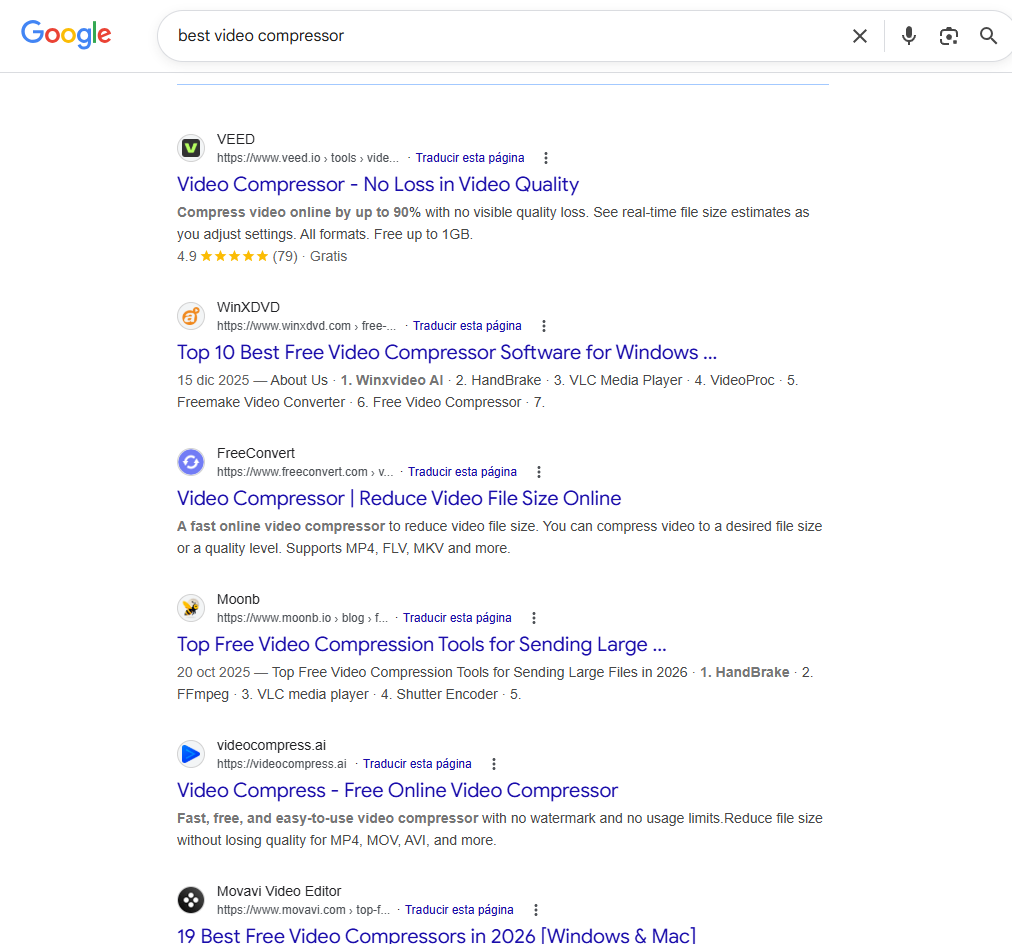
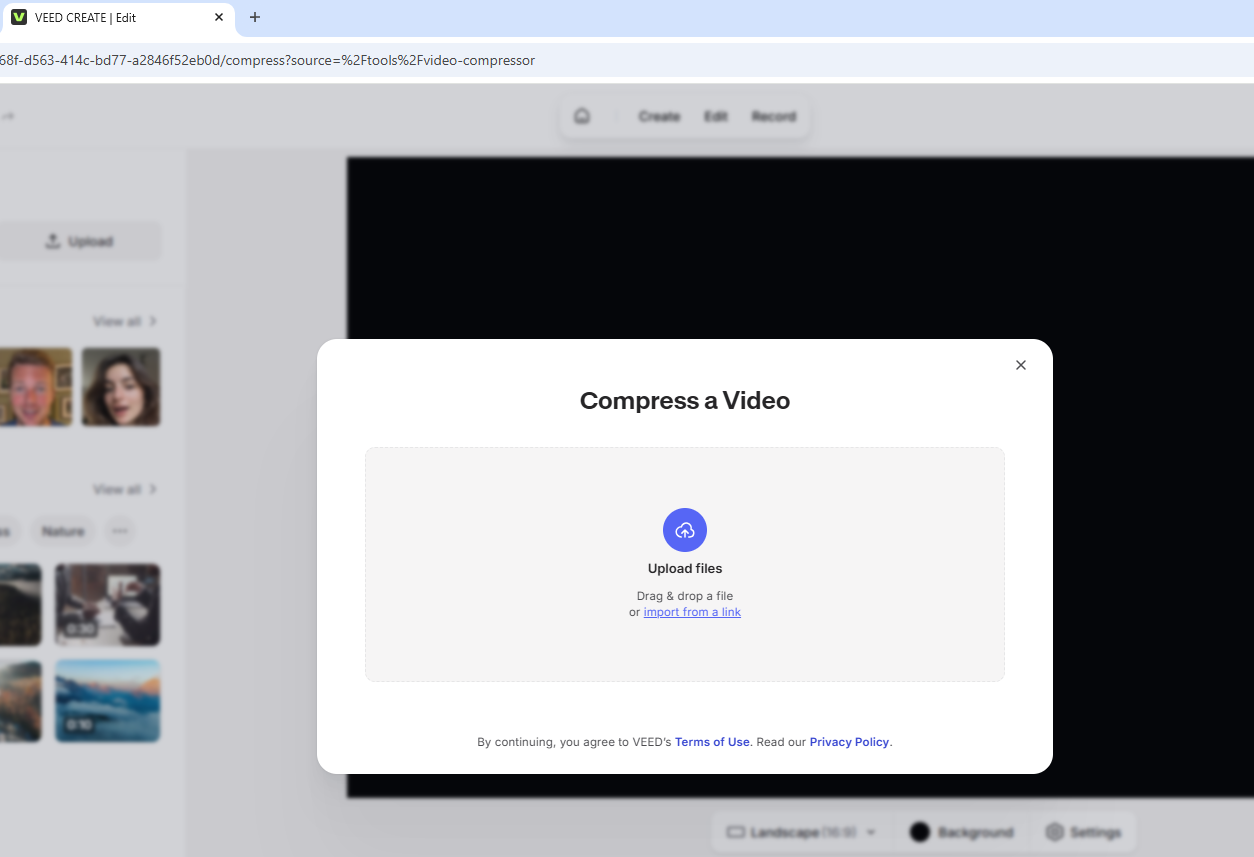
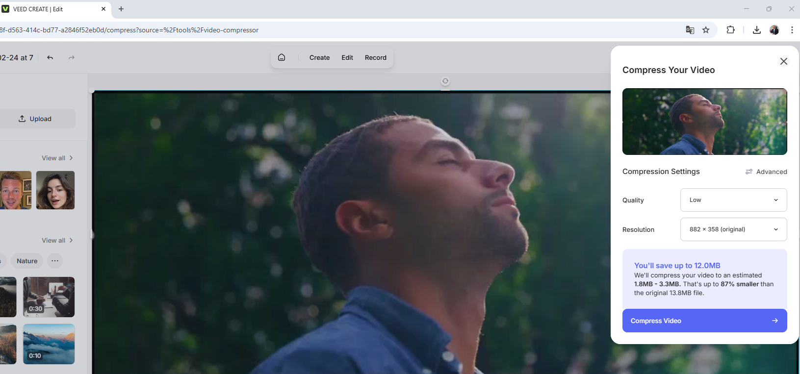
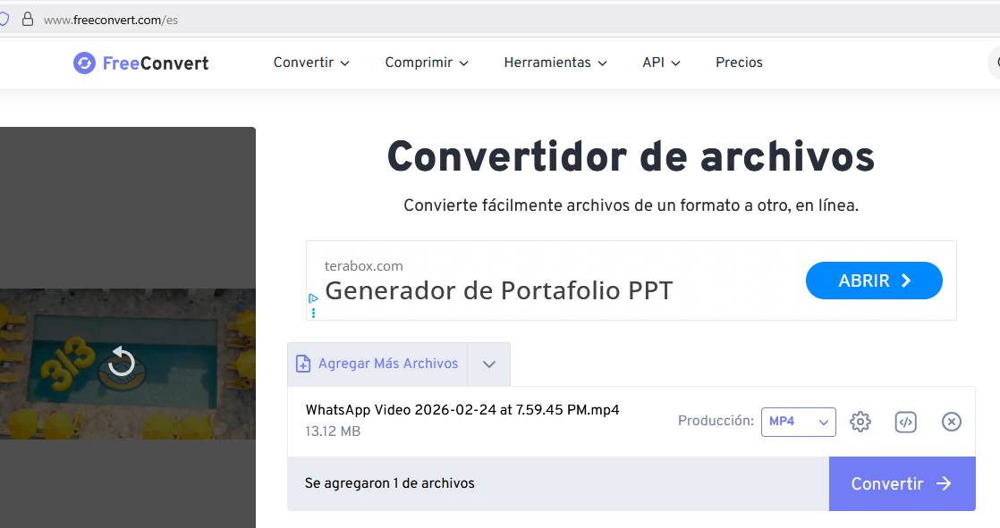
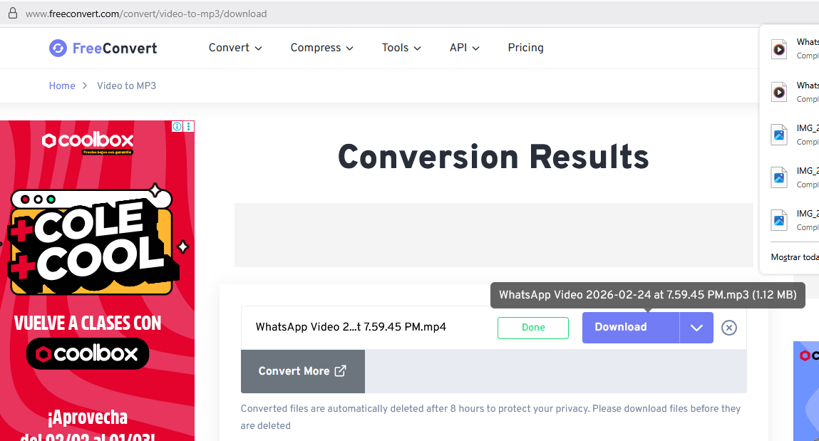
- A lot of tools
- We used Veed and Free Convert
- One option is save with other format
8) Final results
- Modelled experimental objetcts/parts of a final project in a 2D and 3D software
- Shown how you do it with words, images and screenshots
- Documented how you compress your image and videos files
- Included your original design files