Video
Slide
General Description
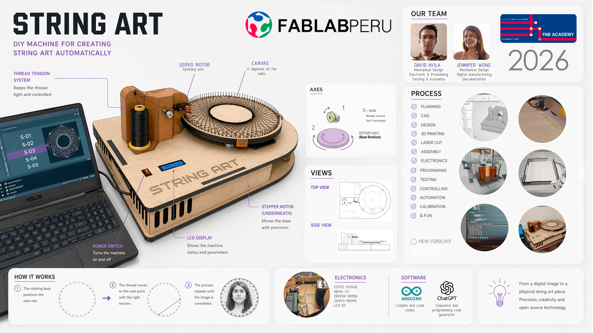
StringArt is a digital fabrication machine that automates the creation of string art compositions through the control of a motion system and the management of a continuous thread. Based on a digital image or pattern, the machine positions the thread between defined points on a surface, generating complex forms and visual gradients.
Quick data
- Project: StringArt
- Type: Automated digital fabrication machine
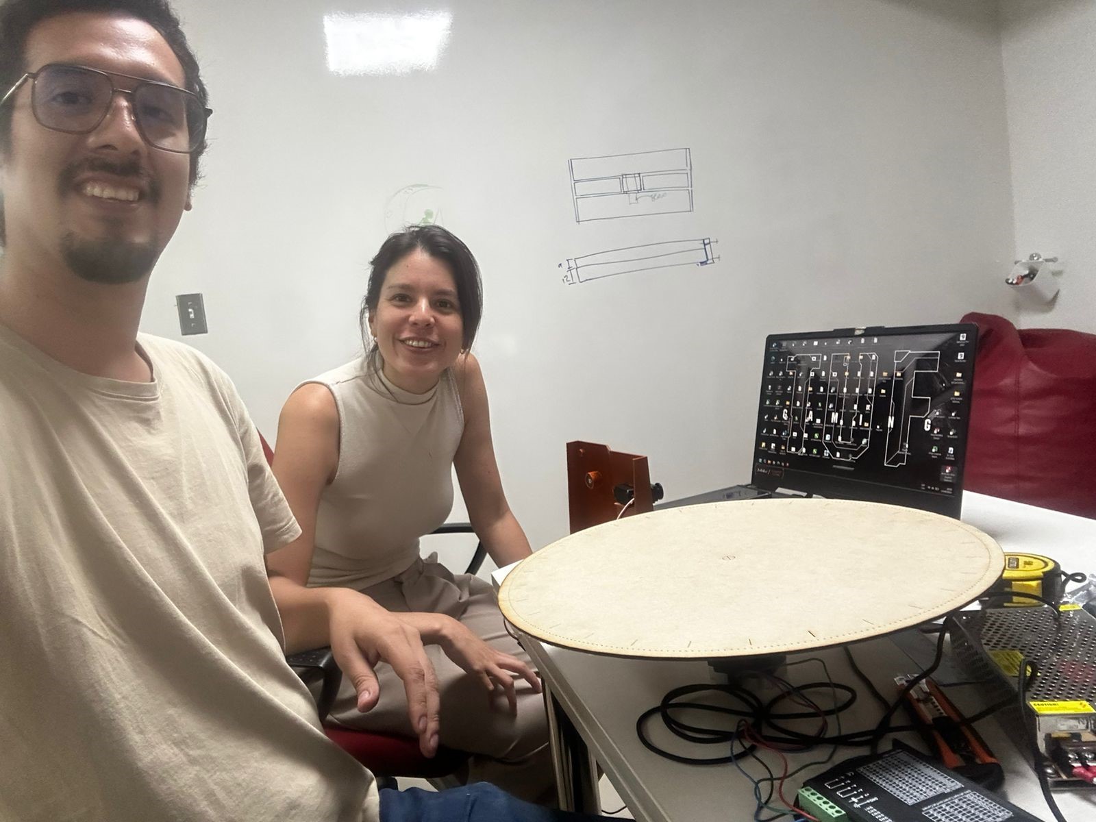
- Team: David Avila, Jennifer Wong
- Main systems: Mechanics, electronics, programming
What is the project?
StringArt is designed to transform digital images into physical string art pieces by automatically positioning thread between predefined anchor points on a circular base.
What is it for?
The system significantly reduces the time and precision required in the manual string art process. It can be used in artistic, educational, and digital fabrication contexts, connecting computational design, numerical control, and mechanical systems.
What makes it interesting?
The project is particularly interesting due to the integration of multiple systems within a single machine: CNC-like controlled motion, computational logic for trajectory generation, and a physical thread control mechanism that introduces an additional layer of complexity.
Unlike other digital fabrication systems, this project combines technical precision with a highly expressive visual result, exploring the intersection between art, design, and technology.
String Art Machine
Team Members
- David Avila
- Jennifer Wong
Project Concept
The project was conceived as an automated machine capable of translating a digital design into a physical string art composition through motion control and thread management.
Problem, User, and Main Idea
Problem
The traditional string art creation process is highly manual, repetitive, and dependent on user precision. It requires time, coordination, and consistency in thread tension, which limits the complexity of designs and makes it difficult to reproduce precise or scalable results.
User or Context
The project is aimed at designers, artists, and students interested in exploring new forms of digital fabrication and visual expression. It is also conceived as an educational tool within digital fabrication laboratories where programming, electronics, and mechanics are connected through creative applications.
Main Idea
To develop an automated machine capable of translating a digital design into a physical string art composition through motion control and thread management. The system executes predefined trajectories between points, enabling complex patterns in a precise, repeatable, and efficient manner.
Development Process
The development of StringArt was carried out iteratively, progressing from a conceptual exploration to the construction of an integrated mechanical system. Each stage allowed the identification of specific problems and guided design decisions, particularly in relation to motion stability and thread control, which proved to be the main challenge of the project.
Stage 1: System Definition and Initial Exploration
In the first stage, the general approach of the project was defined. Based on the analysis of existing machines, a configuration based on a rotating base was selected instead of a Cartesian CNC-type system, as this significantly reduced mechanical complexity and facilitated fabrication.
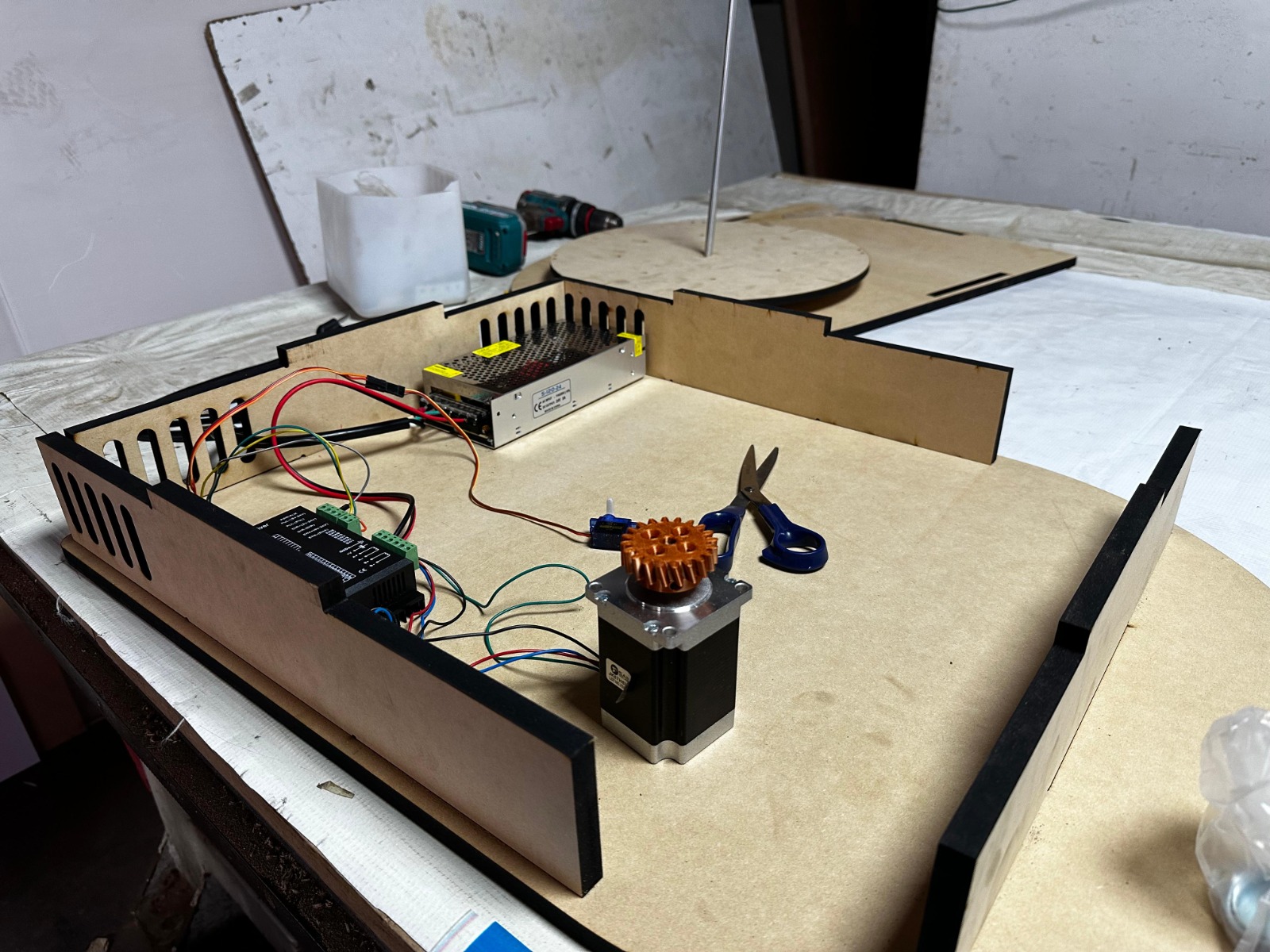
In parallel, research on electronic components was conducted in order to build the bill of materials. Initial tests were carried out on the stepper motor and other electronic components to validate their behavior and compatibility within the system.
At the electronic level, the use of a microcontroller as the central control unit was defined conceptually, establishing the base architecture of the system, although without implementation at this stage.
Audiovisual Record
Stage 2: Rotational System Design
In this stage, the first motion system was developed. A circular MDF base was built with an initial distribution of nails, which allowed the working geometry to be established and the concept of rotation as the main mechanism to be validated.
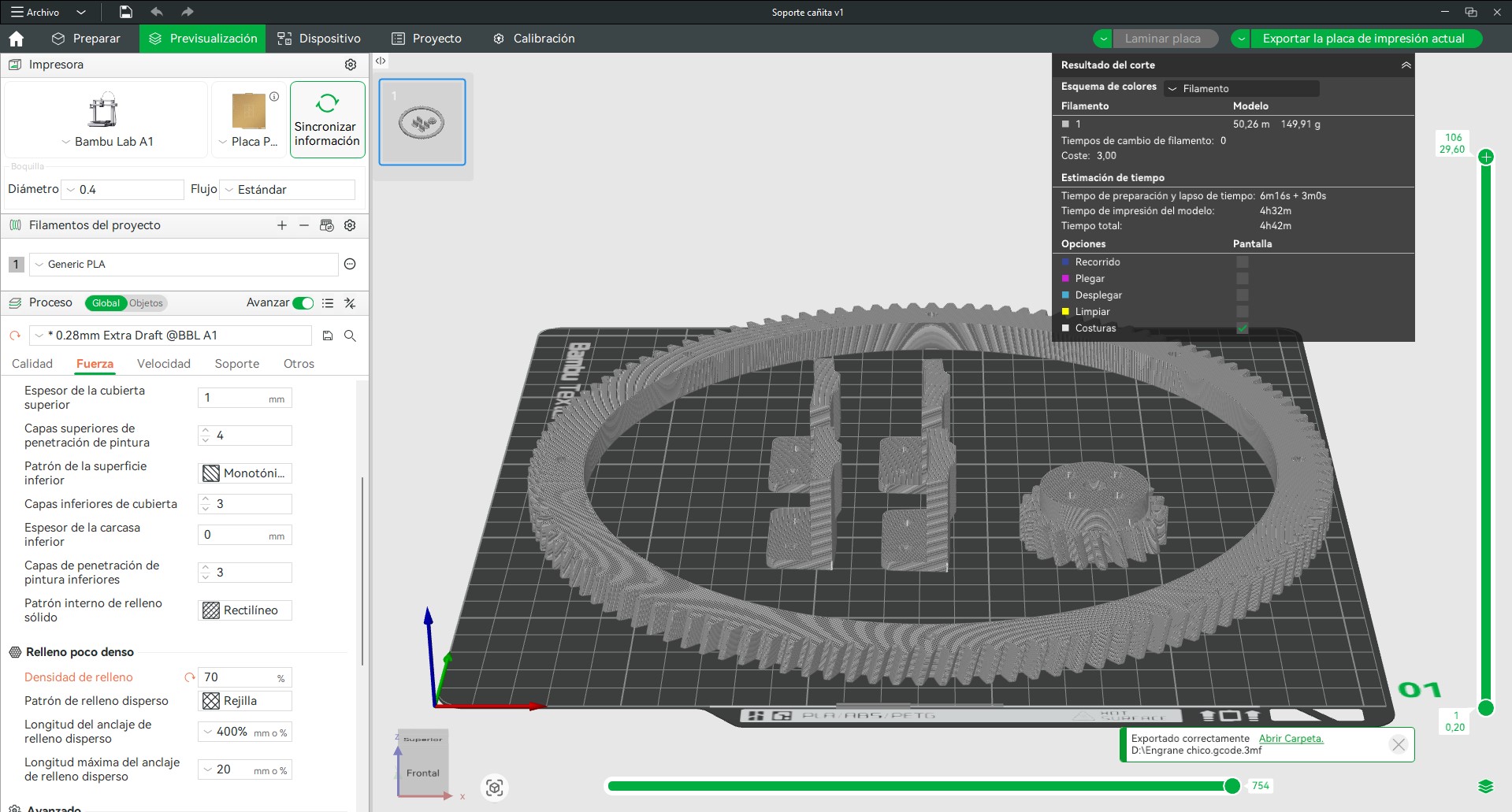
A stepper motor was integrated to evaluate movement, initially without an optimized transmission system. From this, the use of a gear system was explored to improve motion control, analyzing transmission ratios and reduction.
A configuration was implemented where the motor shaft used a 20-tooth gear, while the main plate incorporated a 120-tooth gear, achieving a reduction that improves angular resolution and positioning control.
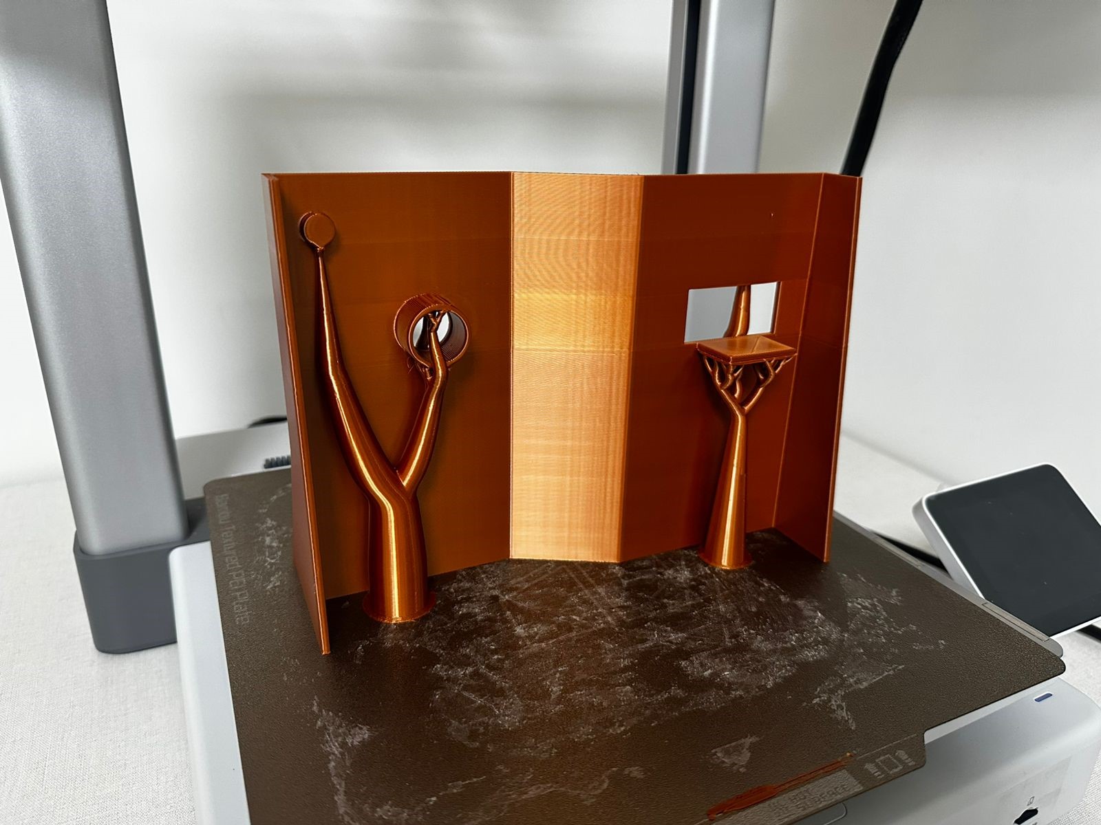
In parallel, the first servo holder was designed and 3D printed, allowing the exploration of the position, orientation, and dimensions of the thread guiding system.
// Pines
#define STEP_PIN 2   // D2
#define DIR_PIN  4   // D4

void setup() {
  pinMode(STEP_PIN, OUTPUT);
  pinMode(DIR_PIN, OUTPUT);

  digitalWrite(DIR_PIN, HIGH); // Dirección inicial
}

void loop() {

  // Girar en un sentido
  digitalWrite(DIR_PIN, HIGH);

  for (int i = 0; i < 2000; i++) { // pasos
    digitalWrite(STEP_PIN, HIGH);
    delayMicroseconds(500); // velocidad
    digitalWrite(STEP_PIN, LOW);
    delayMicroseconds(500);
  }

  delay(1000);

  // Cambiar dirección
  digitalWrite(DIR_PIN, LOW);

  for (int i = 0; i < 2000; i++) {
    digitalWrite(STEP_PIN, HIGH);
    delayMicroseconds(500);
    digitalWrite(STEP_PIN, LOW);
    delayMicroseconds(500);
  }

  delay(2000);
}
Audiovisual Record
Photographic Record
Stage 3: Structural and Component Design
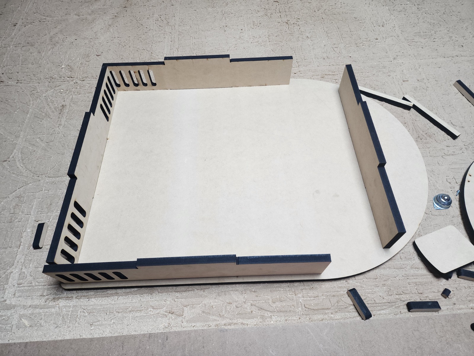
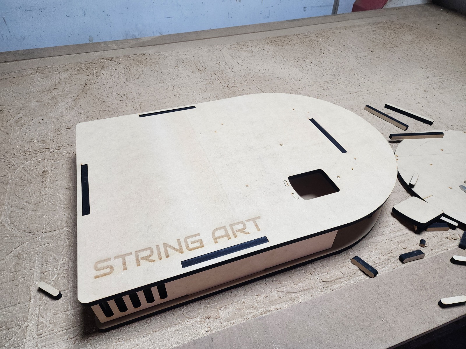
In this stage, the structural system was developed. The enclosure was designed using 12 mm MDF and fabricated through laser cutting, allowing a precise and modular construction.
The distribution of electronic components within the structure was defined, considering accessibility, organization, and future integration.
Components of the thread guiding system were redesigned, optimizing their geometry to improve rigidity and alignment. Additionally, lateral supports were incorporated to hold the base plate where the piece is constructed, increasing the structural stability of the system.
Furthermore, the support system for the rotating base was designed using ballcasters, reducing friction and improving movement stability.
Photographic Record
Stage 4: Testing and Validation
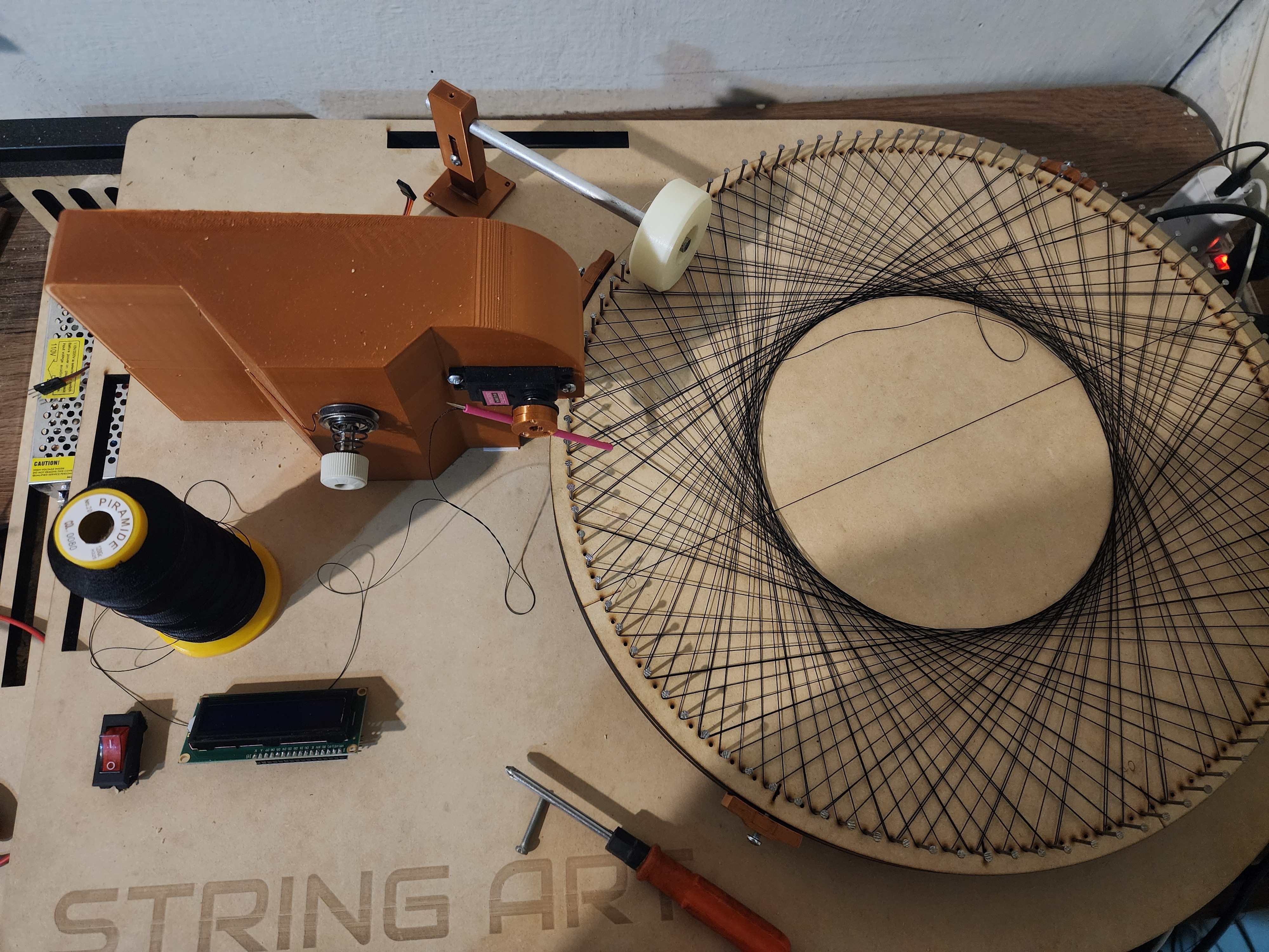
Functional tests of the system were carried out by preparing the canvas with different nail configurations and evaluating the behavior of both motion and thread.
- Motion calibration proved to be complex, especially in relation to the number of nails.
- Configurations with around 250 nails significantly increased control difficulty, while configurations closer to 100 nails provided better results.
- Mechanical issues appeared in the guiding system, such as deformation of the needle or contact element.
- The thread tension system was unstable, leading to loss of trajectory control.
- The thread feeding system experienced tangling due to variations in tension.
- The electronic integration was not yet fully implemented, which limited system control.
This stage was critical in identifying that the main problems were not only related to motion, but to the interaction between the mechanical system and thread control.
Stage 5: Improvements and System Integration
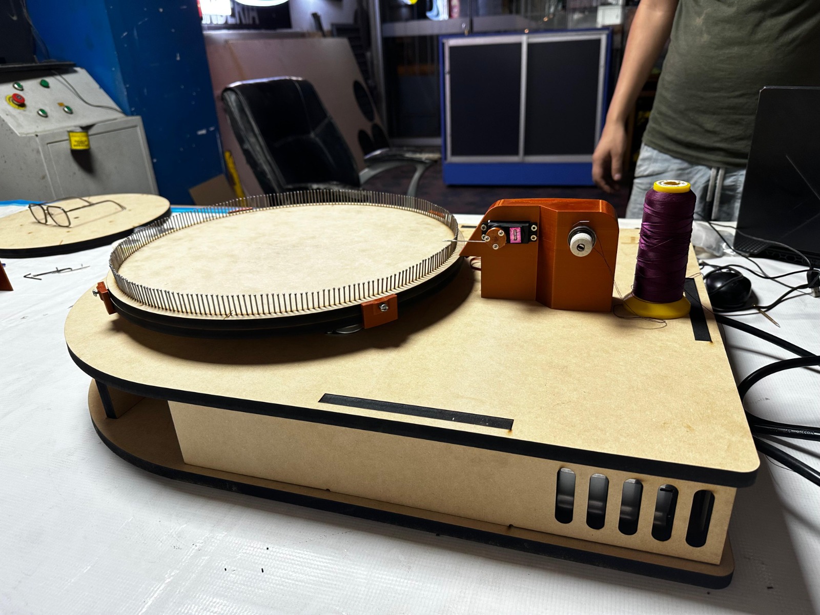
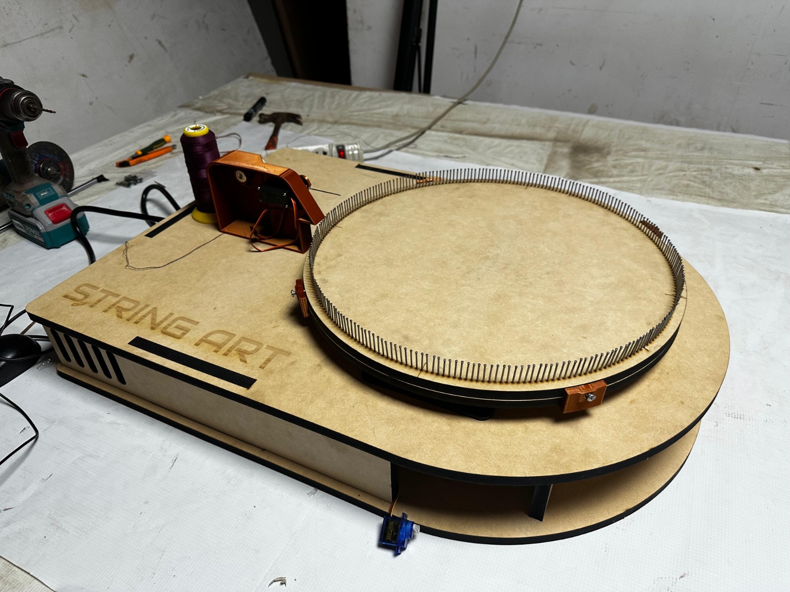
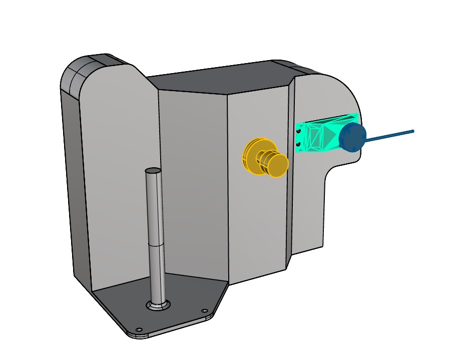
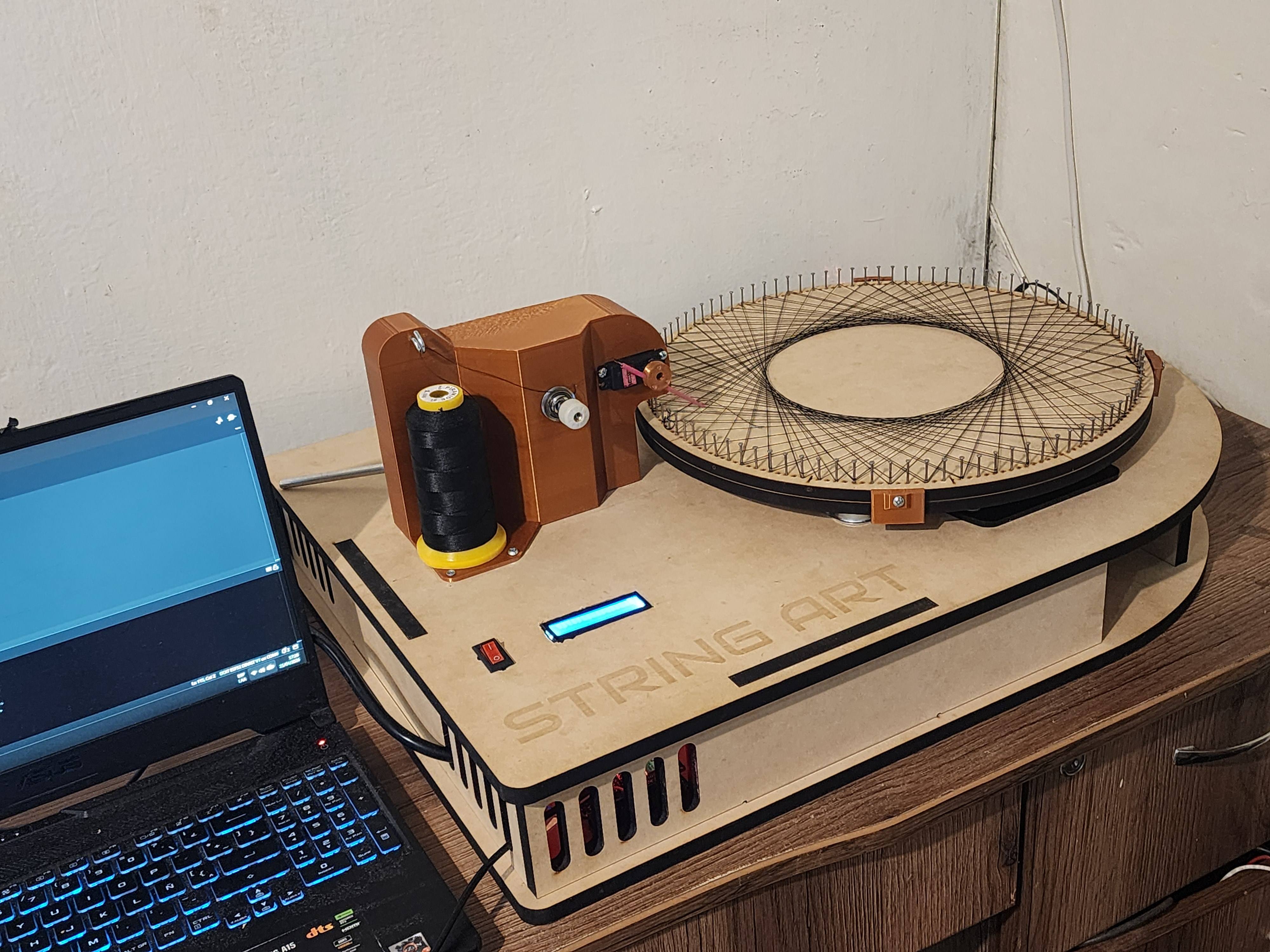
Based on the identified issues, a complete thread guiding and tension system was developed. This system integrates a servo, a guide tube, a mechanical tensioner, a spool holder, and an elevated hook that redirects the thread and prevents tangling.
This set of components enabled effective control of both thread trajectory and tension, solving one of the main challenges of the project.
In parallel, a physical switch was integrated for system power control, and the electronic architecture based on a microcontroller was consolidated, preparing the machine for the execution of digitally generated trajectories.
This stage marks the transition from a functional prototype to an integrated system, where coordination between mechanics, electronics, and programming begins to consolidate.
Photographic Record
Final Proposal
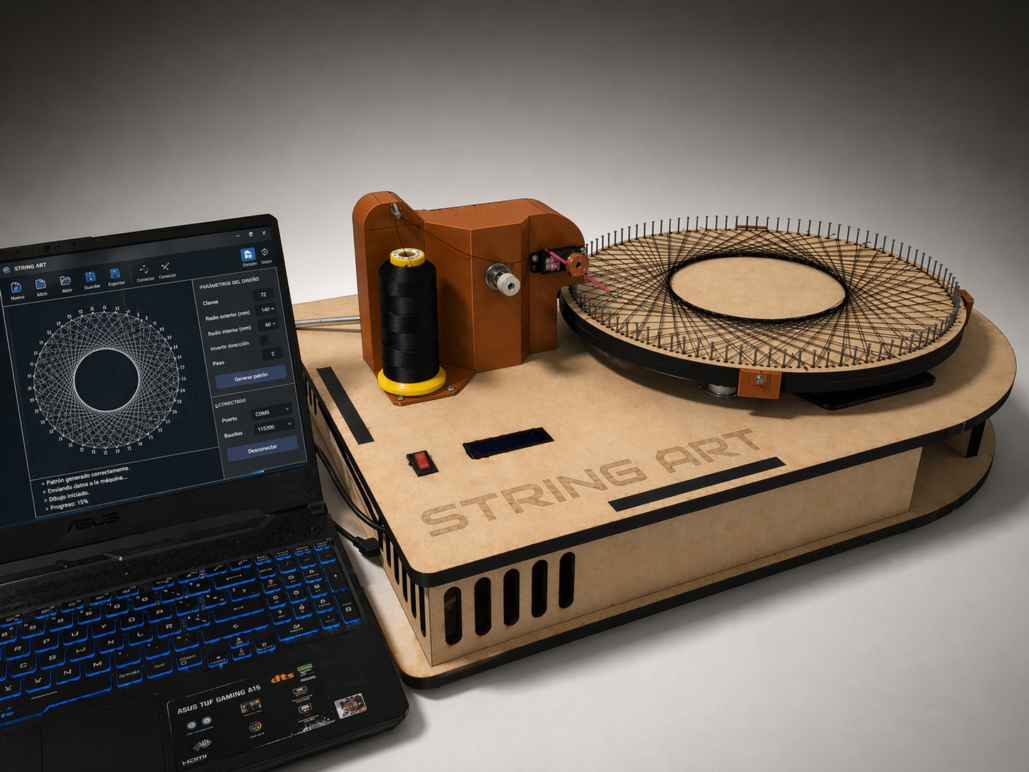
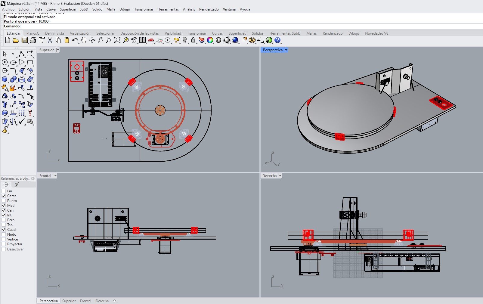
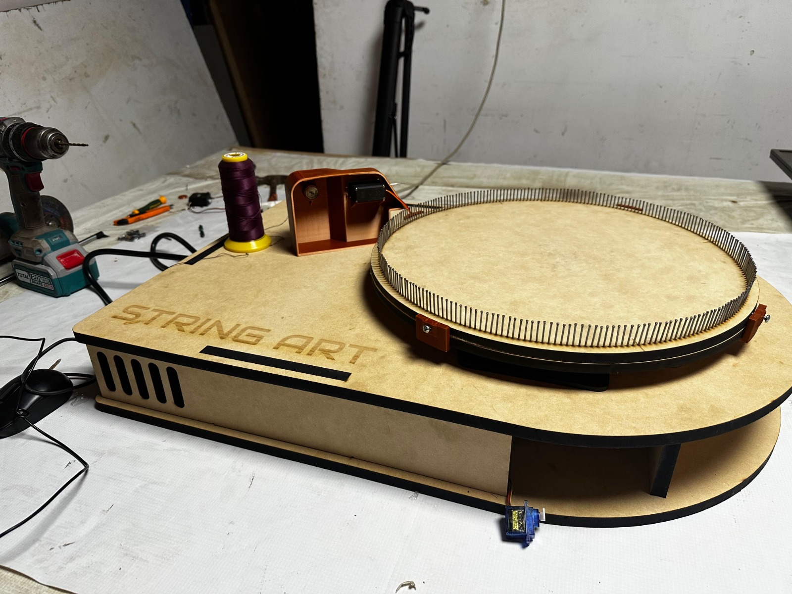
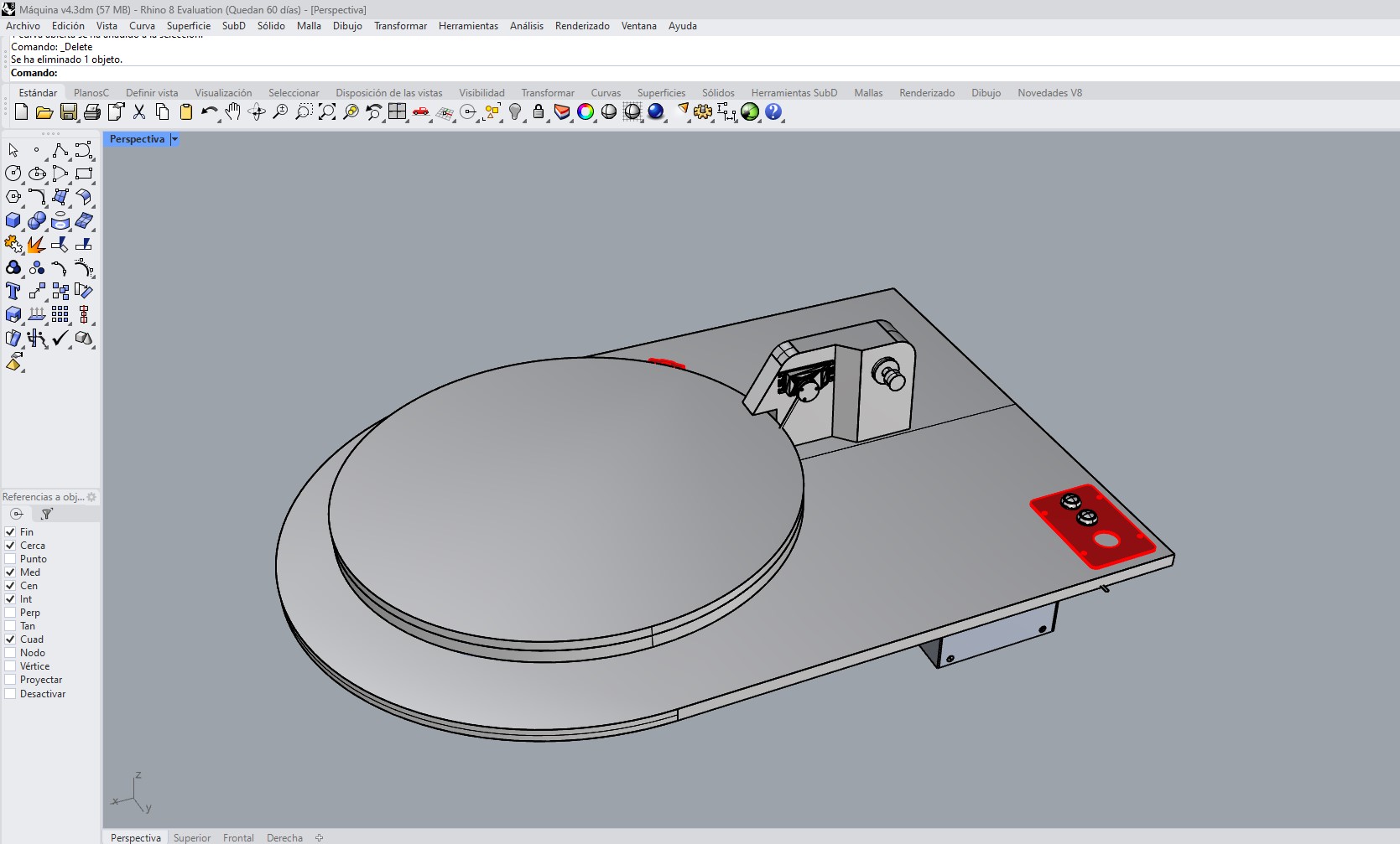
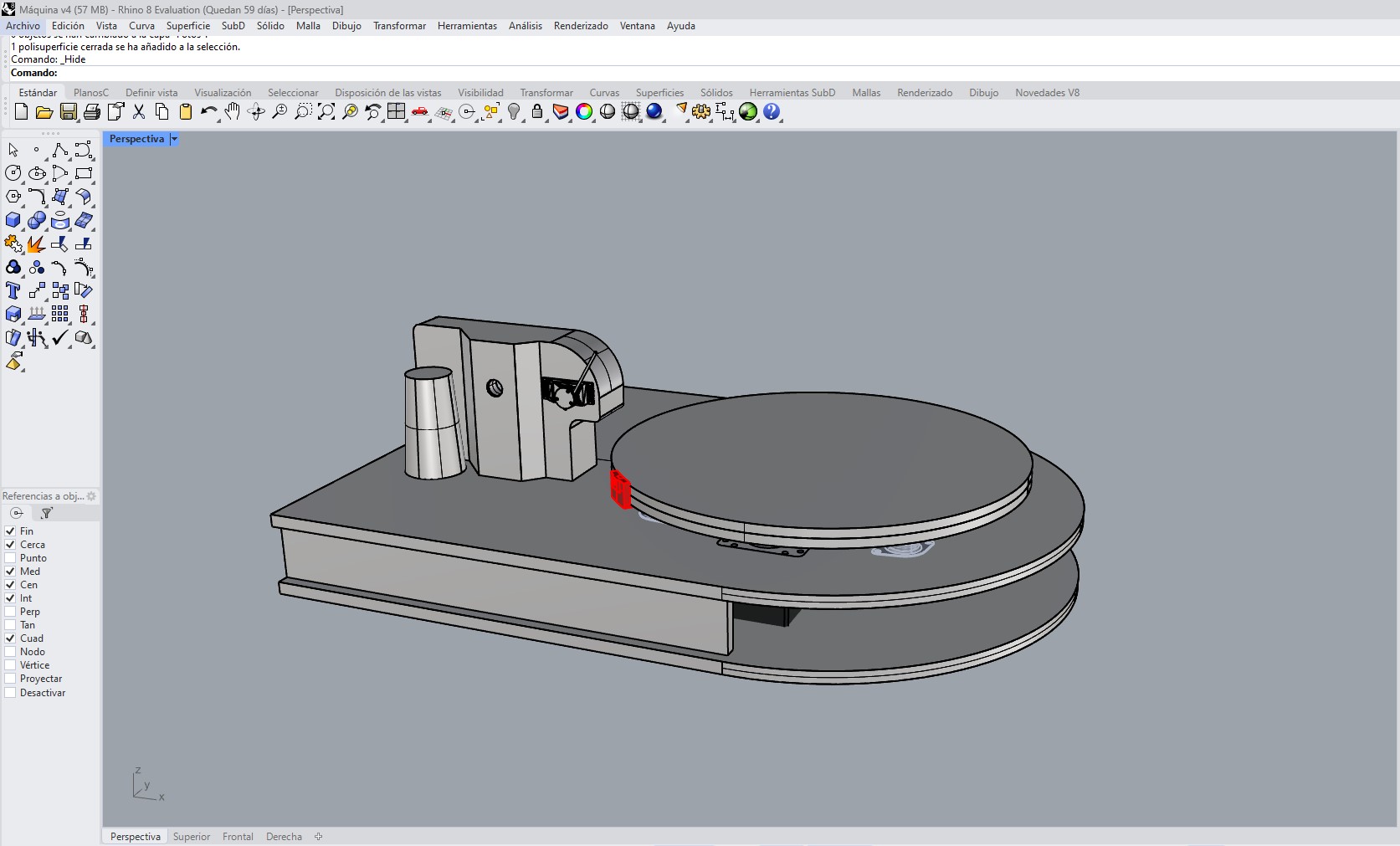
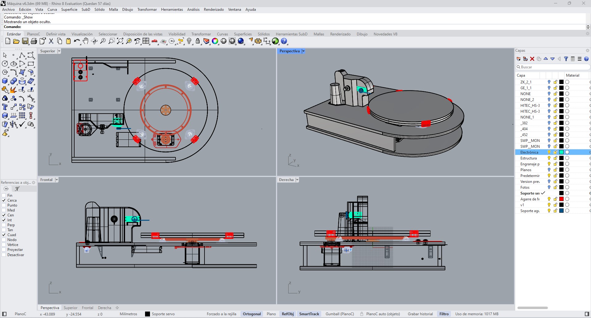
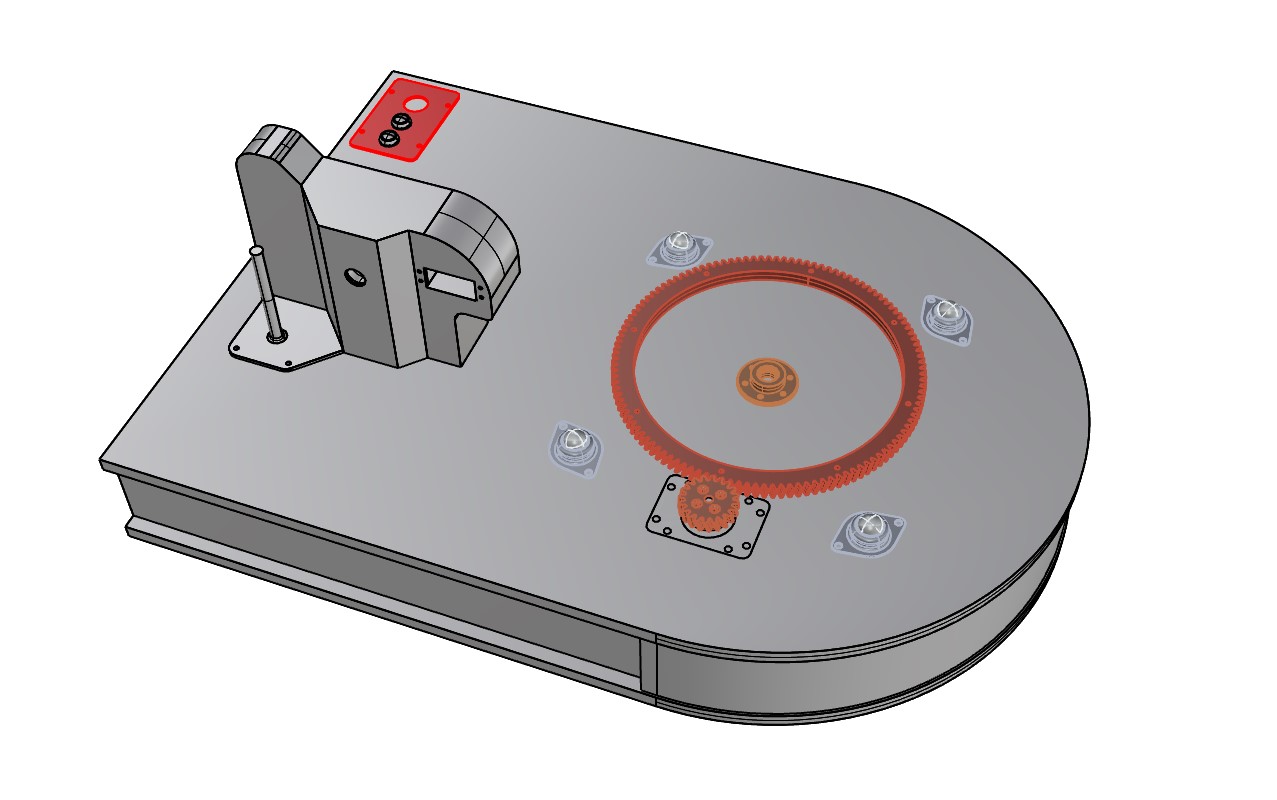
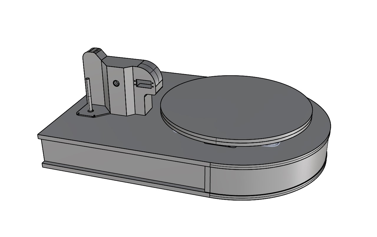
The StringArt system is designed as a digital fabrication machine that integrates a rotating mechanism, a thread guiding system, and an electronic control architecture. Its operation is based on the precise coordination between mechanical motion and thread tension control.
5.1 Motion System
The main motion of the system is based on a circular rotating base made of 12 mm MDF, on which between 100 and 200 nails are distributed along the perimeter, defining the working geometry.
Rotation is driven by a NEMA 17 stepper motor, which transmits motion through a system of 3D-printed gears. This configuration allows adjustment of rotational speed, improves angular positioning control, and increases precision in pattern execution.
To ensure stability during rotation, the base incorporates multiple ballcasters, which reduce friction and distribute load evenly, preventing deformation and vibrations. This combination allows continuous and controlled motion, which is essential for the correct positioning of the thread anchor points.
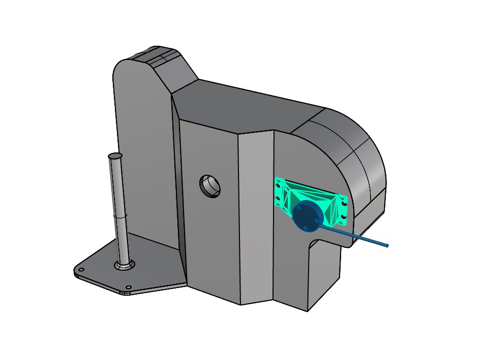
5.2 Thread Guiding and Tension System
The thread system is the most critical component of the project, as it directly defines the quality of the final result. For this purpose, an integrated module was developed that allows control of both the trajectory and tension of the thread during operation.
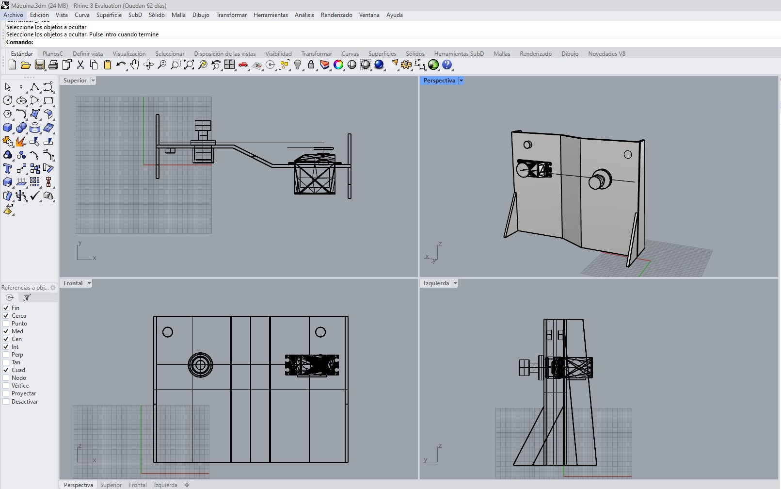
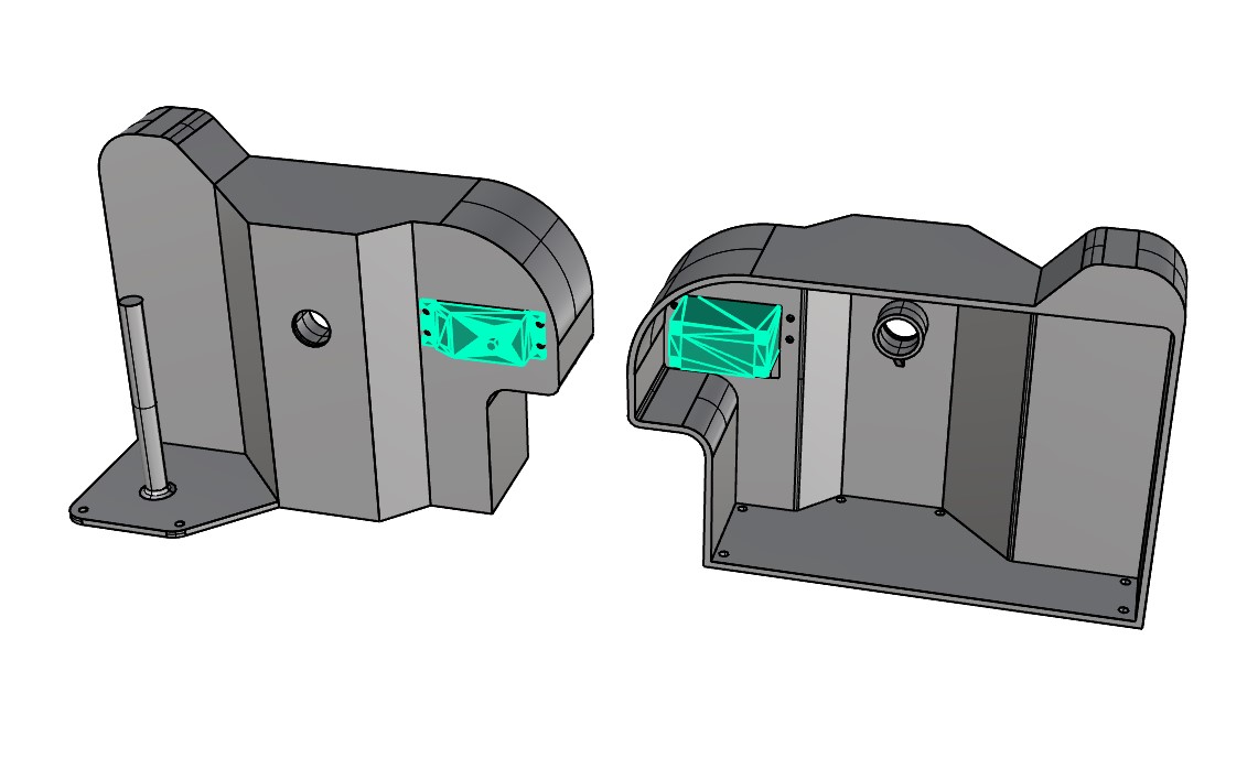
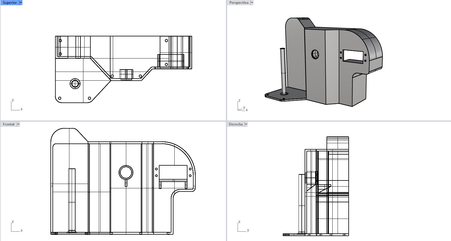
Servo structural support
A CAD-designed and 3D-printed part was developed to fix the servo in a lateral position. This design decision responds to the need to align the movement of the thread with the geometry of the machine, avoiding interference and ensuring proper integration with the rest of the system.
Guide tube coupling
A 3D-printed coupling was incorporated to hold a tube through which the nylon thread moves. This element controls the trajectory of the thread, reduces variability in positioning, and prevents deviations during movement, contributing to more precise pattern execution.
Tension system
Within the same module, a mechanical tensioner was integrated to maintain constant thread tension. This component is fundamental, since insufficient tension results in imprecise patterns, while excessive tension can deform the structure or break the thread.
Spool holder
A feeding system was designed using a spool holder, allowing continuous thread supply without interruptions during the execution process.
Upper guiding system
An elevated hook was incorporated to redirect the thread from the spool to the guiding system. This improves thread alignment, prevents tangling, and maintains a clean trajectory during operation.
Together, these elements transform thread handling into a controlled and repeatable system, solving one of the main challenges of the project.
5.3 Structural System
The overall structure of the system is built in MDF, prioritizing rigidity, ease of fabrication, and low cost as main design criteria. The components were manufactured using laser cutting, allowing precise and consistent cuts while optimizing production time.
The design includes press-fit joints that facilitate assembly without the need for additional fasteners, ensuring proper alignment and structural stability. This approach enables rapid assembly and easy iteration for adjustments.
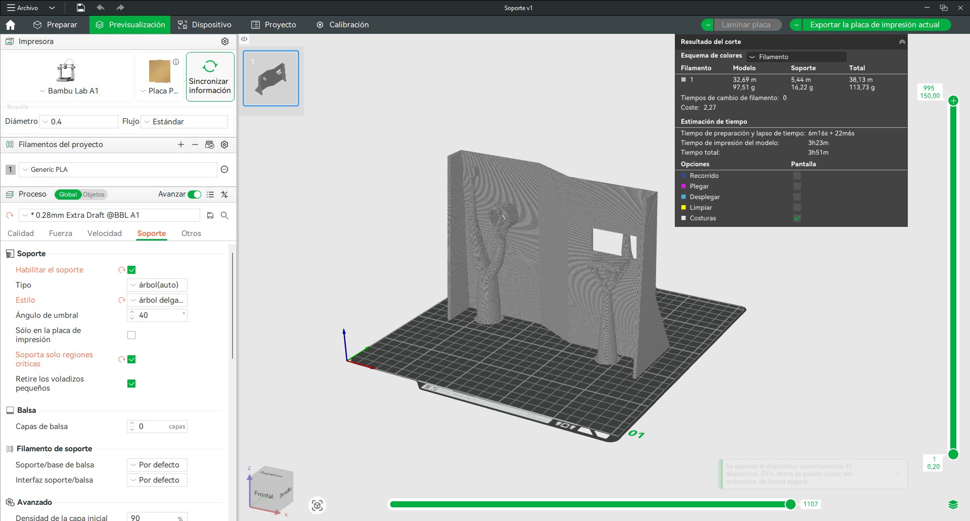
Additionally, 3D-printed components allow the integration of customized parts that would not be feasible with conventional manufacturing, especially in critical elements such as the thread guiding system and the servo support. This combination of technologies facilitates design adaptation and system evolution according to project requirements.
5.4 Electronic System
The electronic system enables control of the machine’s movement and connects digital trajectories with their physical execution. It is composed of an ESP32 microcontroller, a support board, a power driver, a power supply, a stepper motor, and a wiring system.
The ESP32 microcontroller acts as the central unit, processing instructions and generating control signals. These signals are sent to the DM556 driver, which manages the power required to drive the stepper motor, controlling parameters such as direction and rotational speed.
The stepper motor converts these signals into physical motion, allowing controlled rotation of the base. The power supply provides the necessary energy for system operation, while cables and connectors enable interconnection between components.
In this way, the system translates digitally generated trajectories into a sequence of electrical signals that become motion, achieving precise and repeatable pattern execution. A physical switch is also included to safely turn the machine on and off during operation.
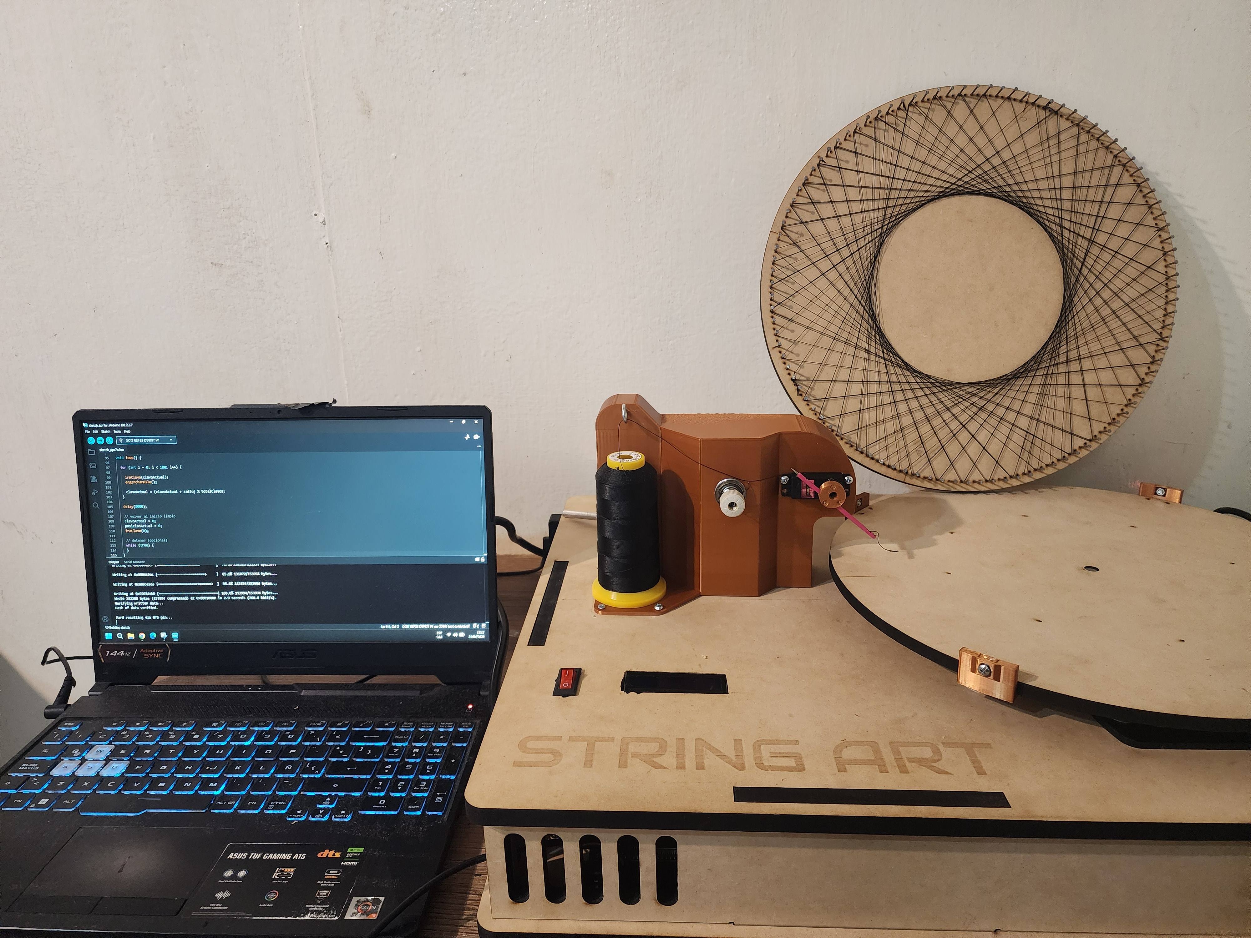
5.5 Programming
The system programming allows control of the machine’s movement and execution of digitally generated trajectories. This logic is implemented in the ESP32 microcontroller, which translates instructions into control signals for the motor.
The system receives as input a sequence of points or trajectories generated by digital tools such as String Art Creator. These trajectories are interpreted by the microcontroller, which generates control signals (pulses) sent to the stepper motor driver.
Based on these signals, the system controls the rotation of the base, managing direction and speed, allowing correct positioning of thread anchor points. This establishes the connection between computational design and physical execution.
The implemented logic enables continuous execution of movement sequences, ensuring process repeatability. The system is also prepared for future improvements, such as trajectory optimization or integration of feedback sensors.
#include
#include
#include

// ---------------- LCD ----------------
LiquidCrystal_I2C lcd(0x27, 16, 2);

// ---------------- PINES ----------------
const int stepPin = 14;
const int dirPin  = 27;
const int servoPin = 13;

// ---------------- SERVO ----------------
Servo aguja;

const int ANGULO_ARRIBA = 40;
const int ANGULO_ABAJO  = 5;

// ---------------- CONFIG ----------------
const float pasosPorVuelta = 9600.0;
const int totalClavos = 100;

const int offsetAngular = 3;
const int pasosOffset = 85;

// 🔥 SECUENCIA OPTIMIZADA
int secuencia[] = {
  0,17,34,51,68,85,2,19,36,53,70,87,4,21,38,55,72,89,6,23,
  40,57,74,91,8,25,42,59,76,93,10,27,44,61,78,95,12,29,46,63,
  80,97,14,31,48,65,82,99,16,33,50,67,84,1,18,35,52,69,86,3,
  20,37,54,71,88,5,22,39,56,73,90,7,24,41,58,75,92,9,26,43,
  60,77,94,11,28,45,62,79,96,13,30,47,64,81,98,15,32,49,66,83
};

const int totalPasos = sizeof(secuencia) / sizeof(secuencia[0]);

// ---------------- VARIABLES ----------------
float posicionActual = 0.0;

unsigned long tiempoInicio = 0;
unsigned long ultimoLCD = 0;
unsigned long ultimoSerial = 0;

int progresoGlobal = 0;

// ---------------- LCD ----------------

void actualizarLCD() {

  if (millis() - ultimoLCD < 200) return;
  ultimoLCD = millis();

  unsigned long tiempoActual = millis() - tiempoInicio;

  int segundos = tiempoActual / 1000;
  int minutos = segundos / 60;
  segundos = segundos % 60;

  lcd.setCursor(0, 0);
  lcd.print("String Art 1.0");

  lcd.setCursor(0, 1);
  lcd.print("Prog: ");

  if (minutos < 10) lcd.print("0");
  lcd.print(minutos);
  lcd.print(":");
  if (segundos < 10) lcd.print("0");
  lcd.print(segundos);

  lcd.setCursor(12, 1);

  if (progresoGlobal < 100) lcd.print(" ");
  if (progresoGlobal < 10) lcd.print(" ");

  lcd.print(progresoGlobal);
  lcd.print("%");
}

// ---------------- SERIAL ----------------

void actualizarSerial(int i, int origen, int destino) {

  if (millis() - ultimoSerial < 300) return;
  ultimoSerial = millis();

  unsigned long tiempoActual = millis() - tiempoInicio;

  int segundos = tiempoActual / 1000;
  int minutos = segundos / 60;
  segundos = segundos % 60;

  Serial.print("[");
  if (minutos < 10) Serial.print("0");
  Serial.print(minutos);
  Serial.print(":");
  if (segundos < 10) Serial.print("0");
  Serial.print(segundos);
  Serial.print("] ");

  Serial.print("Paso ");
  Serial.print(i);
  Serial.print(" | ");

  Serial.print(origen);
  Serial.print(" -> ");
  Serial.print(destino);

  Serial.print(" | ");
  Serial.print(progresoGlobal);
  Serial.println("%");
}

// ---------------- MOTOR ----------------

void stepMotor(long pasos, bool dir) {
  digitalWrite(dirPin, dir);

  for (long i = 0; i < pasos; i++) {
    digitalWrite(stepPin, HIGH);
    delayMicroseconds(500);
    digitalWrite(stepPin, LOW);
    delayMicroseconds(500);
  }
}

void irAClavo(int clavo) {

  float pasosObjetivo = (pasosPorVuelta * clavo) / totalClavos;

  float delta = pasosObjetivo - posicionActual;
  bool sentido = (delta >= 0);

  if (sentido) pasosObjetivo += offsetAngular;
  else pasosObjetivo -= offsetAngular;

  delta = pasosObjetivo - posicionActual;

  stepMotor(abs((long)delta), sentido);

  posicionActual += (long)delta;
}

// ---------------- SERVO ----------------

void bajarAguja() {
  aguja.write(ANGULO_ABAJO);
  delay(200);
}

void subirAguja() {
  aguja.write(ANGULO_ARRIBA);
  delay(200);
}

void engancharHilo() {

  bajarAguja();
  stepMotor(pasosOffset, HIGH);
  subirAguja();
}

// ---------------- SETUP ----------------

void setup() {
  pinMode(stepPin, OUTPUT);
  pinMode(dirPin, OUTPUT);

  aguja.attach(servoPin);
  subirAguja();

  lcd.init();
  lcd.backlight();

  Serial.begin(115200);
  Serial.println("=== INICIO STRING ART ===");

  lcd.setCursor(0, 0);
  lcd.print("String Art 1.0");
  lcd.setCursor(0, 1);
  lcd.print("Iniciando...");
  delay(2000);

  lcd.clear();

  tiempoInicio = millis();
}

// ---------------- LOOP ----------------

void loop() {

  for (int i = 0; i < totalPasos - 1; i++) {

    progresoGlobal = (i * 100) / totalPasos;

    int origen = secuencia[i];
    int destino = secuencia[i + 1];

    actualizarLCD();
    actualizarSerial(i, origen, destino);  // 🔥 serial fluido

    irAClavo(origen);
    engancharHilo();
  }

  // -------- FIN --------

  unsigned long tiempoTotal = millis() - tiempoInicio;

  int segundos = tiempoTotal / 1000;
  int minutos = segundos / 60;
  segundos = segundos % 60;

  lcd.clear();

  lcd.setCursor(0, 0);
  lcd.print("String Art 1.0");

  lcd.setCursor(0, 1);
  lcd.print("Finish! ");

  if (minutos < 10) lcd.print("0");
  lcd.print(minutos);
  lcd.print(":");
  if (segundos < 10) lcd.print("0");
  lcd.print(segundos);

  Serial.println("=== TERMINADO ===");

  while (true) {
  }
}
5.6 System Integration
System integration consisted of connecting and synchronizing mechanical, electronic, and programming components, allowing the machine to function as a unified system.
The operation flow begins with the generation of digital trajectories from an image using tools such as String Art Creator. These trajectories are processed by the microcontroller, which interprets the required movement sequence.
The microcontroller then sends signals to the stepper motor driver, which drives the rotation of the base through the gear system. This movement, combined with the thread guiding and tension system, positions the thread between defined points, generating the physical pattern.
Proper integration ensures precise movement, controlled thread trajectory, and consistent results. During this stage, adjustments were made in mechanical alignment, system stability, and motion response to ensure continuous and reliable operation.
Audiovisual Record
Photographic Record
Challenges and Learnings
The development of StringArt presented several challenges, mainly related to motion precision and the integration between the mechanical system and control logic.
One of the first challenges was achieving stable rotation of the base, as initial versions showed issues with friction, imbalance, and vibrations. These factors directly affected system repeatability and generated cumulative errors in pattern execution.
However, the most critical challenge was found in programming and in the synchronization between digital trajectories and the physical movement of the machine.
At a learning level, the project demonstrated that precision in digital fabrication does not depend solely on mechanical design, but on the correct integration of software, electronics, and physical structure.
Conclusions
StringArt evolved from a conceptual mechanical exploration into an integrated digital fabrication system. The process made clear that the main difficulty was not only movement control, but the synchronization between mechanics, electronics, and thread behavior. The project shows how iterative development is essential when dealing with fabrication systems that combine technical precision and expressive results.
Bill of Materials
| System | Component | Quantity | Model / Specification | Supplier (Peru) |
|---|---|---|---|---|
| Structure | M5/M6 Screws | Set | Various | Sodimac |
| MDF Base | 1 | 12 mm | Sodimac | |
| Base Board | 1 | MDF 12 mm | Sodimac | |
| Motion | Stepper Motor | 1–2 | JK57HS76-2804 (NEMA 23, 2.8A, 1.89 Nm) | SAISAC |
| Gears | 1 set | 3D printed | DIY | |
| Steel Shaft | 1 | Stainless steel | Malvinas | |
| Thread System | Spool Holder | 1 | 3D printed / metal | DIY |
| Tension System | 1 | Mechanical tensioner + springs | Sodimac | |
| Guide Tube | 1 | Plastic | DIY | |
| Nails | 100–300 | According to design | Sodimac | |
| Electronics | Microcontroller | 1 | ESP32 + shield | SAISAC |
| LCD Display | 1 | LCD 1602 with I2C module | Electromanía | |
| Driver | 1 | DM556 | SAISAC | |
| Power Supply | 1 | 24V 5A (120W) | SAISAC | |
| Logic Level Converter | 1 | 4CH 5V–3.3V | SAISAC | |
| Relay Module | 1 | 5V Relay (1 channel) | SAISAC | |
| Cables and Connectors | Set | Dupont / 14AWG | SAISAC | |
| Extras | Ballcasters | 4–8 | Ball caster wheels | SAISAC |
| Power Switch | 1 | ON/OFF switch | SAISAC | |
| Solder Paste | 1 | YH-351 (35g) | Mastertronics |
References
Reference Machines
- String Art Machine – Instructables
- StringBoard Machine
- StringIT Automated String Art Machine – Instructables
- Reddit Discussion – 3D Printed String Art Machine