Assignment Requirements
Individual assignment
- Design and document the system integration for your final project.
Assignment Requirements
Learning outcomes
- Define and apply system integration to your final project.
Have you answered these questions?
- Define and apply system integration to your final project.✅
- Documented your processdocumented your plan with CAD and/or sketches for system integration?.✅.
- implemented methods of packaging?.✅.
- designed your final project to look like a finished product?.✅.
- documented system integration of your final project?.✅.
- linked to your system integration documentation from your final project page?.✅.
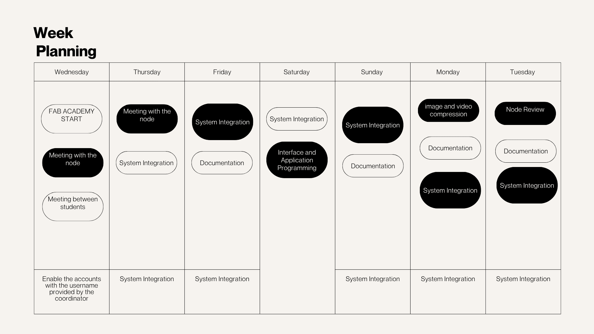
Weekly planning
During this week, the planning focused on the integration of all the project subsystems into a single functional prototype. The work included organizing the mechanical structure, electronics, embedded programming, interaction system, power supply, and the final physical enclosure.
The integration process also involved testing the communication between hardware and software, improving component distribution, and verifying that all systems worked together correctly. In addition, the knowledge acquired throughout the course was applied by combining programming, electronics, 3D design, digital fabrication, and interface development to achieve a more stable, interactive, and organized final result.
The goal this week was to integrate all the previously developed project
subsystems into a single, functional prototype. This included integrating
the mechanical structure, electronics, embedded programming, interaction
system, power supply, and final physical enclosure.
The aim was not only to verify that each subsystem functioned correctly
individually, but also to evaluate the project's behavior as a complete,
functional, and interactive system with a more organized and professional appearance.
Individual Assignment
System Design and Furniture Planning
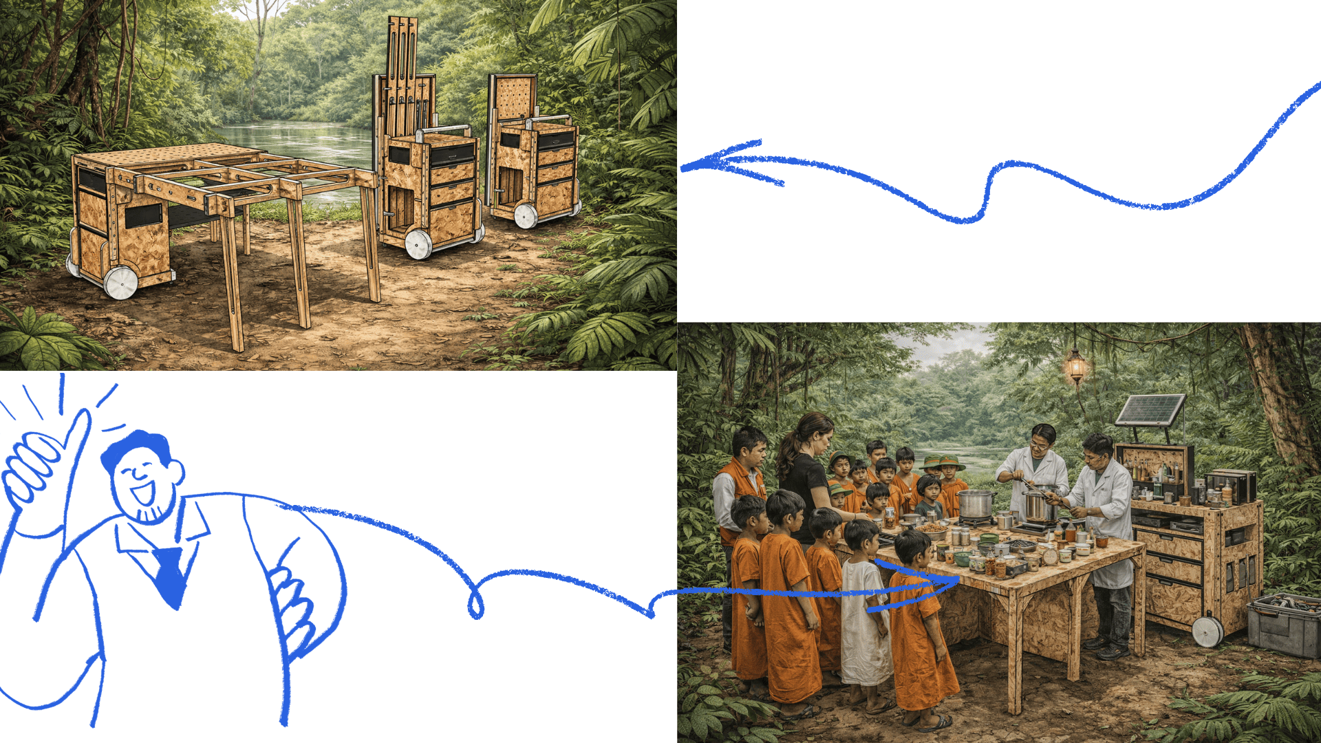
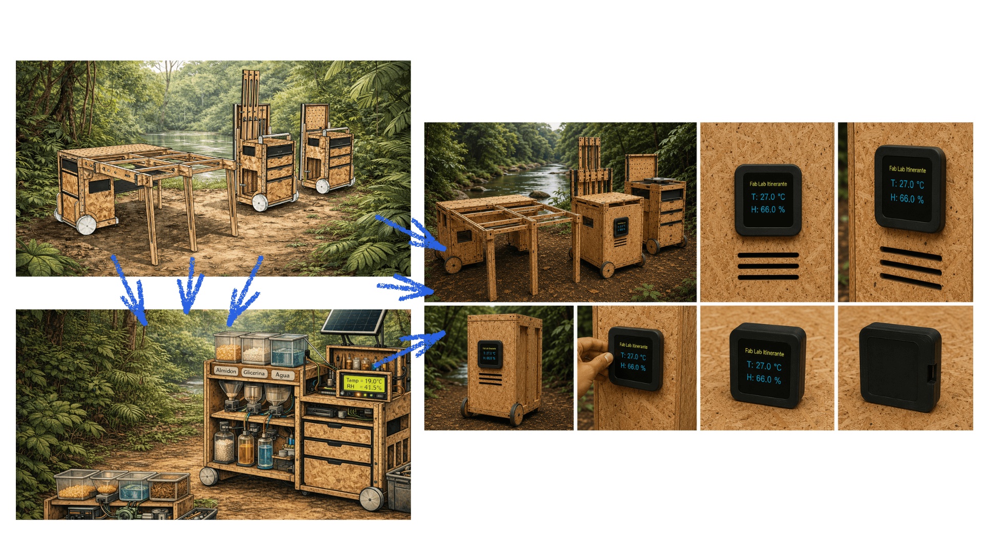
The design of the Mobile Laboratory furniture system was developed based on the experience of workshops carried out in the Peruvian Amazon and the need to transport educational kits, technological tools, and laboratory equipment to different communities. Due to the territorial and fluvial conditions of the Amazon region, the project aimed to create a portable, resistant, and adaptable solution.
The project was conceived as a modular and detachable mobile furniture unit, designed to be easily transported in the trunk of a car or by boat. In addition, the design sought to integrate different systems into a single piece of furniture, combining storage, workspace, and energy supply within one functional structure.
As part of the digital fabrication process, CNC technology was considered for the design and cutting of the structural parts of the furniture, allowing greater precision, easier assembly, and the possibility of replicating the system in future versions.
The furniture functions as a durable storage chest that protects mobile workshop and laboratory kits from humidity, rain, and continuous field use. When deployed, it transforms into a foldable and extendable worktable, creating a functional workspace in communities where access to basic furniture is limited.
In addition, the system integrates solar panels and a battery storage system to provide renewable energy for charging phones, lamps, and essential electronic devices in areas where electrical infrastructure is limited or nonexistent.
- Modular and detachable design adaptable to different workshops and activities.
- Portable format suitable for transportation by car or boat.
- Digital fabrication using CNC technology for precision and assembly.
- Secure storage system for kits and equipment.
- Integrated solar panel and battery storage system.
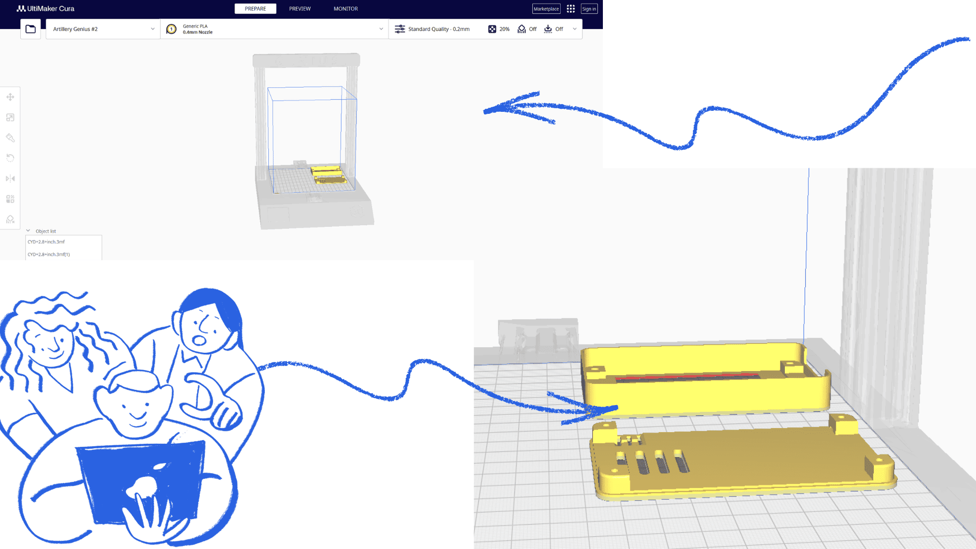
3D Printed PCB Case
As part of the system integration, a custom 3D printed case will be developed to protect and organize the PCB and electronic components of the Mobile Laboratory project.
The case is designed to securely hold the electronic system while protecting it from dust, humidity, and external impacts during transportation and field use. In addition, the enclosure will be incorporated directly into the furniture structure, allowing better organization and easier access to the electronic components.
Through the use of 3D printing, the design can be adapted to the dimensions of the PCB, cable management, ventilation needs, and assembly system, creating a more integrated, functional, and professional final prototype.
Electronic System Integration
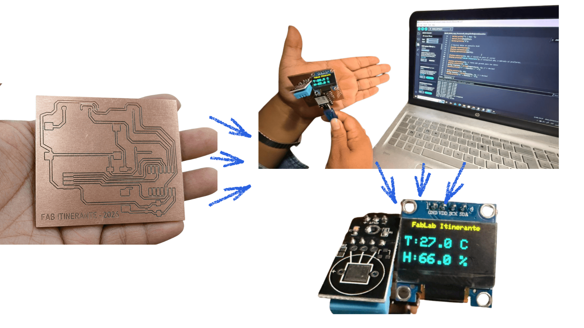
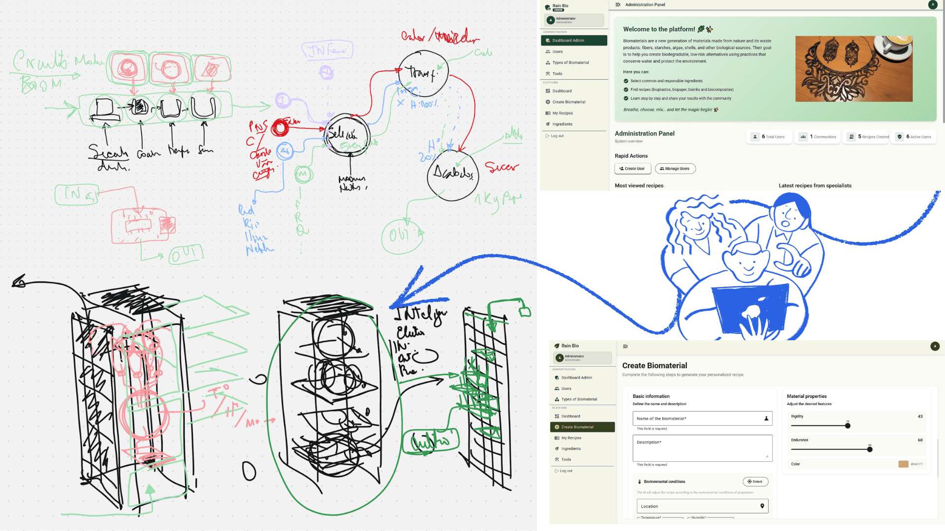
The system operates through the integration of sensors, electronic components, and embedded programming connected to the XIAO ESP32-C3 microcontroller. The electronic design was developed and adapted using KiCad, starting from a previously created motherboard that was modified according to the needs of the Mobile Laboratory project.
After verifying that all the required libraries were correctly installed, the FabLab library was incorporated into KiCad to ensure compatibility with the selected components and footprints. From this base design, the necessary components were selected, adapted, and connected to the Xiao ESP32-C3.
During the schematic design process, components such as the DHT11 temperature and humidity sensor, LDR light sensor, OLED display, LED feedback system, servomotor, switch, and battery input were integrated and correctly connected to the ESP32-C3 according to the technical specifications of the microcontroller.
The use of a motherboard optimized the development process; however, it also required additional validation, pin assignment verification, and adjustments to ensure the proper integration and communication of all electronic subsystems.
The complete system includes:
- XIAO ESP32-C3 microcontroller
- DHT11 temperature and humidity sensor
- LDR light sensor
- OLED display (I2C communication)
- Servomotor
- LED feedback system
- SPDT switch
- Battery power input system
- External pin connectors
- Integrated programming logic
- 3D printed protective case for the PCB
Development of the Monitoring and Control System for Biomaterial Drying
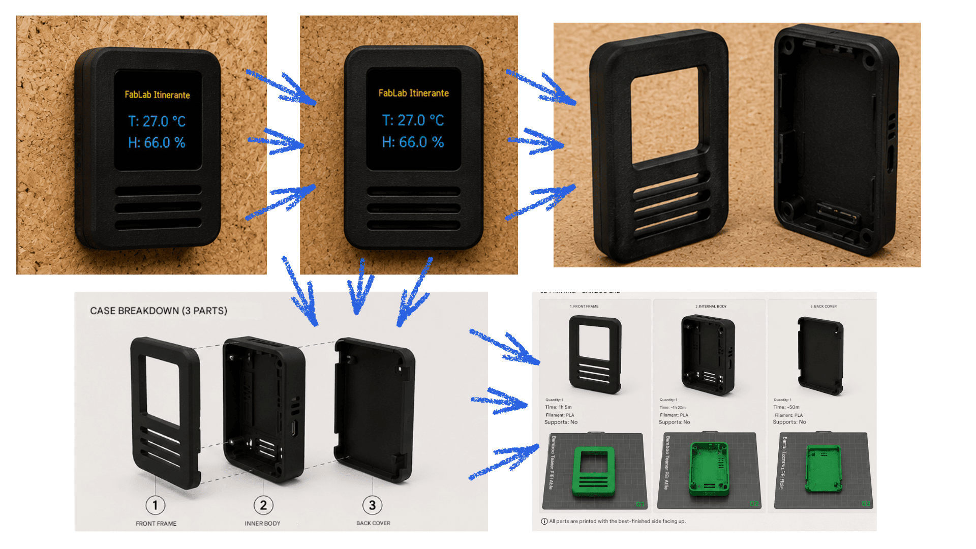
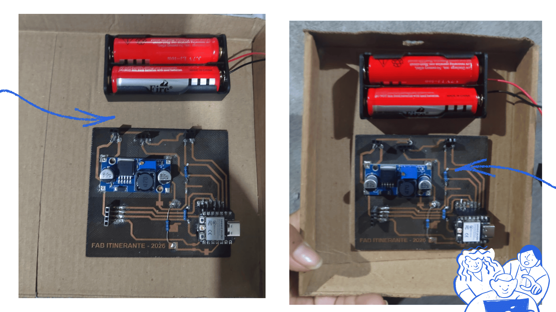
As part of my contribution to the project, I participated in the development of the environmental monitoring system for the biomaterial drying module. During the initial stage, I built a cardboard mock-up to evaluate the overall dimensions of the enclosure, the placement of the electronic board, the battery, and the components required for the final prototype. This preliminary model helped validate the spatial arrangement and identify design requirements before moving to digital fabrication.
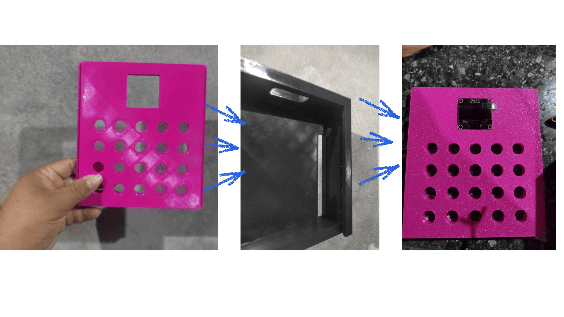
Based on these observations, I designed and developed several 3D models, producing multiple iterations through 3D printing until achieving a functional and optimized enclosure. The final design allowed efficient integration of the electronic components while maximizing the available internal space.
The enclosure incorporated dedicated channels for cable routing and organization, improving assembly, maintenance, and overall system reliability. In addition, a ventilation grid was integrated into the design to promote airflow within the drying chamber and improve environmental control.
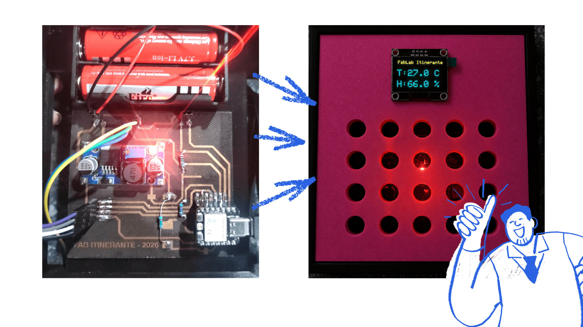
For the electronic system, I integrated a DHT11 sensor to monitor temperature and humidity inside the drying chamber, enabling real-time observation of the conditions required for biomaterial drying. A photoresistor (LDR) was also included to measure light intensity and evaluate its influence on the drying process. Furthermore, the system was designed to operate using battery power, providing portability and autonomous operation.
Through multiple testing and validation stages, the design was refined to improve performance and usability. The final system contributes to better control of internal environmental conditions, supporting a more efficient and controlled biomaterial drying process.

Programming
The following Arduino code was used to connect the XIAO ESP32-C3 with the DHT11 sensor and OLED display, allowing real-time temperature and humidity monitoring.
#include <Wire.h>
#include <Adafruit_GFX.h>
#include <Adafruit_SSD1306.h>
#include <DHT.h>

#define OLED_RESET -1
Adafruit_SSD1306 display(128, 64, &Wire, OLED_RESET);

const int DHTPIN = 21;
#define DHTTYPE DHT11

DHT dht(DHTPIN, DHTTYPE);

void setup() {

  Serial.begin(115200);

  Wire.begin();

  if(!display.begin(SSD1306_SWITCHCAPVCC, 0x3C)) {
    Serial.println(F("SSD1306 allocation failed"));
    for(;;);
  }

  display.display();
  delay(2000);
  display.clearDisplay();

  dht.begin();

  Serial.println("Initialization complete.");
}

void loop() {

  delay(2000);

  float humidity = dht.readHumidity();
  float temperatureC = dht.readTemperature();

  if (isnan(humidity) || isnan(temperatureC)) {

    Serial.println("Error reading DHT11 sensor.");

    display.clearDisplay();
    display.setCursor(0,0);
    display.print("Sensor Error!");
    display.display();

    return;
  }

  Serial.print("Temp: ");
  Serial.print(temperatureC);
  Serial.print(" C | Hum: ");
  Serial.print(humidity);
  Serial.println("%");

  display.clearDisplay();

  display.setTextSize(1);
  display.setTextColor(WHITE);
  display.setCursor(10, 0);
  display.println("FabLab Itinerante");

  display.setTextSize(2);

  display.setCursor(0, 20);
  String tempValue = String(temperatureC, 1);
  display.println("T:" + tempValue + " C");

  display.setCursor(0, 45);
  String humValue = String(humidity, 1);
  display.println("H:" + humValue + " %");

  display.display();
}
Video (local)
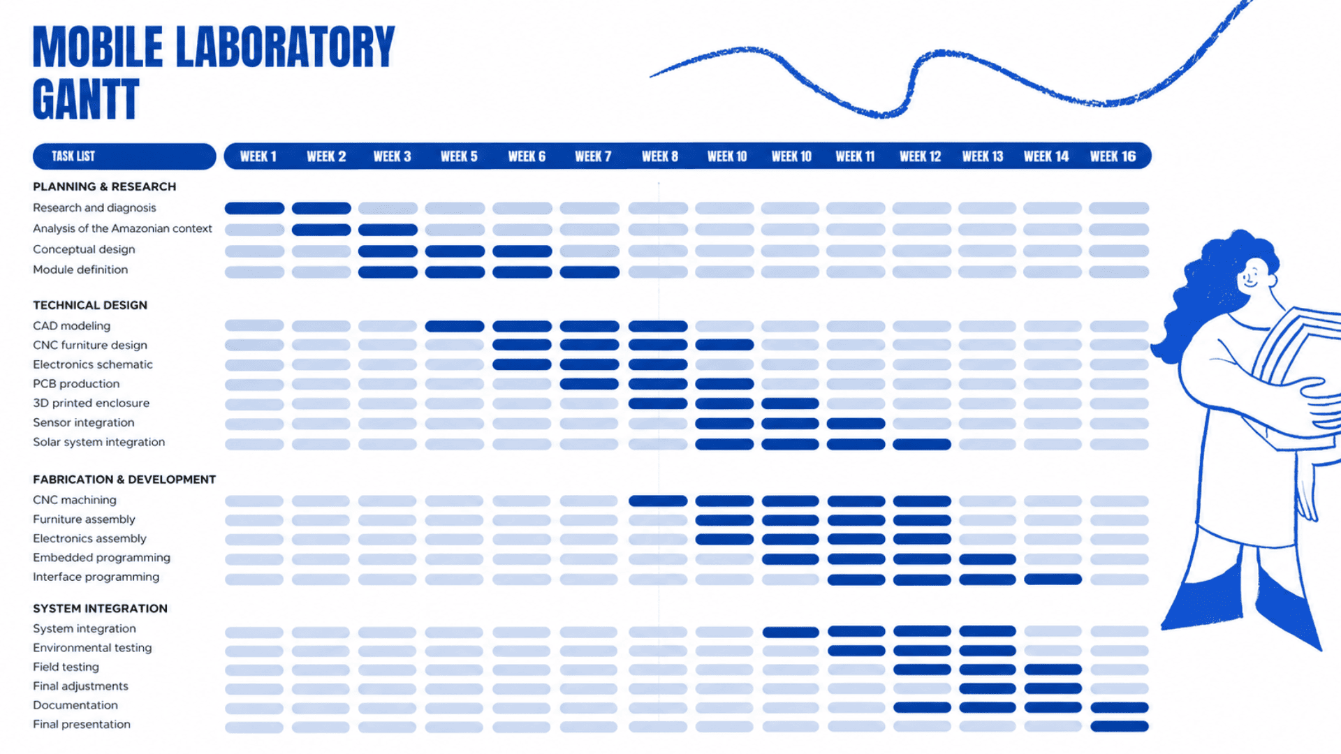
Integration Plan
The Mobile Laboratory project was divided into several subsystems that were progressively integrated throughout the development process to achieve a complete functional prototype.
| Subsystem | Components | Integration Purpose |
|---|---|---|
| Furniture Structure System | Modular furniture, foldable table, storage unit, CNC structure | Provides portability, storage, stability, and workspace integration. |
| Electronic System | PCB, XIAO ESP32-C3, wiring, OLED display, DHT11, LDR | Controls sensor reading, communication, and electronic interaction. |
| Interaction System | OLED display, LED feedback, sensors, switch | Allows user interaction and real-time system feedback. |
| Embedded Programming | Arduino code, sensor monitoring, OLED interface | Manages system behavior, data processing, and component communication. |
| Energy System | Solar panel, battery input, power connections | Provides autonomous and renewable energy to the system. |
| Protection and Enclosure System | 3D printed PCB case, internal supports | Protects electronic components and improves system organization. |
The integration process required multiple iterations because modifications in one subsystem frequently affected the others, especially regarding dimensions, internal space, electronic connections, and component organization inside the furniture.
Lessons Learned
Throughout the development of the Mobile Laboratory project, several important lessons were learned regarding system integration, digital fabrication, and interdisciplinary design.
One of the main lessons was understanding the importance of planning the integration of all subsystems from the beginning. Mechanical design, electronics, programming, energy systems, and physical structure must work together as a complete system rather than as independent parts.
The project also demonstrated the value of iterative prototyping. During the process, multiple adjustments were required in the PCB design, component distribution, furniture dimensions, and wiring organization to ensure proper functionality and compatibility.
Another important lesson was learning how digital fabrication tools such as CNC machining and 3D printing can be integrated into a real-world project to create customized, functional, and adaptable solutions for specific environmental and community needs.
Finally, this experience reinforced the importance of designing technology with context in mind. Developing a portable and autonomous Mobile Laboratory for the Peruvian Amazon required considering transportation, humidity, energy limitations, and accessibility in remote communities.