Assignment Requirements
Group assignment
- Design a machine that includes mechanism + actuation + automation + application.
- Build the mechanical parts and operate it manually.
- Document the group project.
Individual assignment
- Document your individual contribution.
Progress Status
This is for reporting progress (not for visitors to click).
Group page link + notes added.
Missing final photos and conclusions.
Upload .zip with source files.
Assignment Requirements
Learning outcomes
- Work and communicate effectively as a team.
- Design, plan and build a machine.
- Analyse and solve technical problems.
- Recognise opportunities for improvements in the design.
Have you answered these questions?
- Linked to the group assignment page.✅
- Documented your individual contribution to this project on your own website.✅.
- Linked to the group page from your individual page as well as from group page to your individual pages.✅.
- Shown how your team planned, allocated tasks and executed the project (Group page).✅.
- Described problems and how the team solved them (Group page).✅.
- Listed possible improvements for this project (Group page).✅.
- Included your design files (Group page).✅.
- You need to present your machine globally and/or include a 1 min video (1920x1080 HTML5 MP4) + slide (1920x1080 PNG) (Group page).✅.
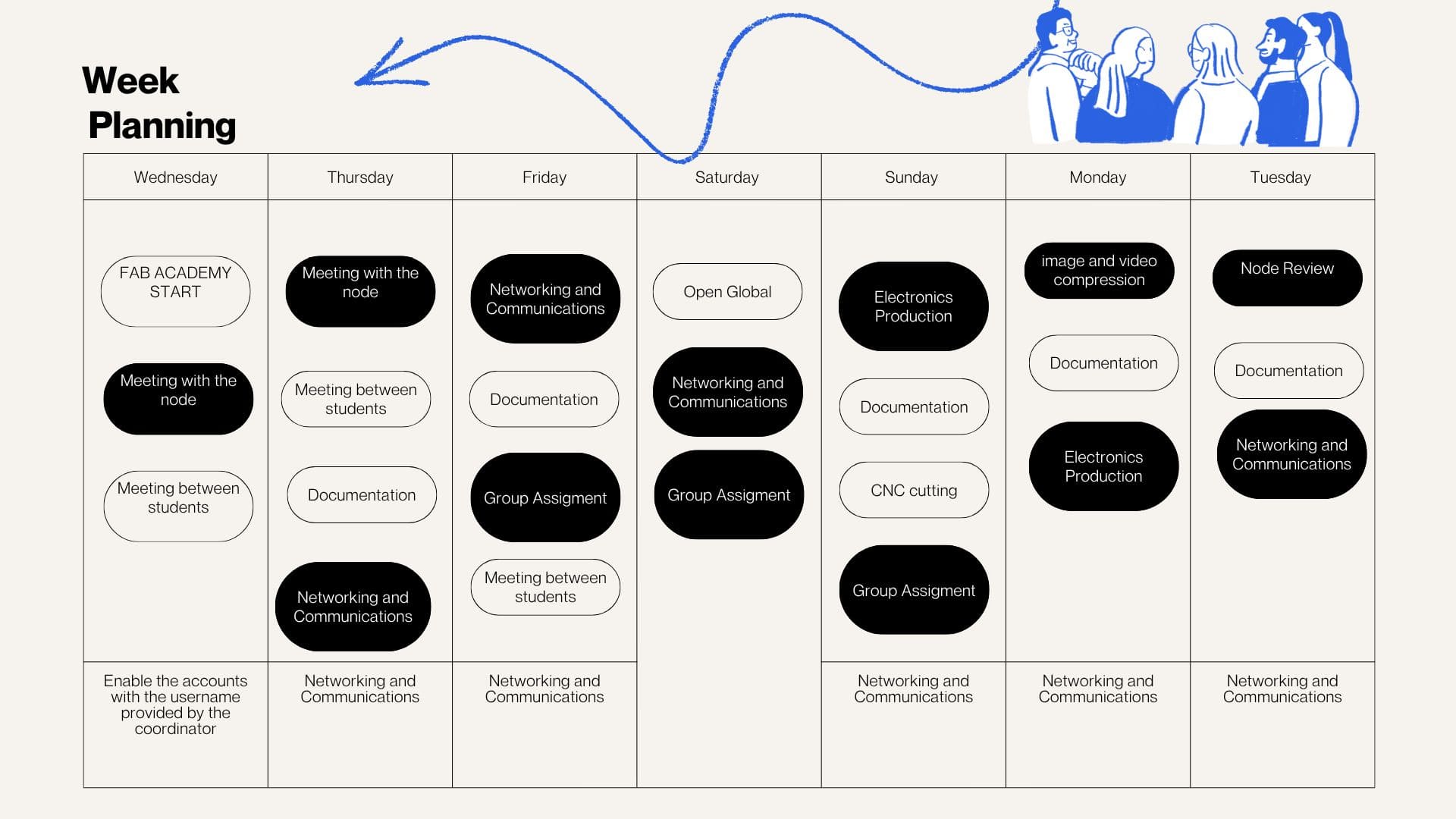
Weekly planning
During the week, we carried out various activities that presented significant challenges but were also very rewarding, especially due to the opportunity to share and learn as a team. We met virtually with our colleagues at the node and participated in lab meetings, which allowed us to organize ourselves and conduct open workshops in different spaces. In these sessions, we reviewed and worked with input devices, understanding their operation and their importance in capturing data from the environment for subsequent processing in electronic systems.
To design a machine focused on producing biomaterials through symbiocreation,
inspired by the Peruvian jungle, with the aim of generating environmental and social impact.
To design a strong and affordable prototype considering available time,
resources, team knowledge, and project requirements.
For more details about the group work and collaborative development, visit the following link:
Group Work – Machine Building
Define the Machine
Ideas
Proposals
Opinions
Problems & Solutions
Problems
Solutions
Define a Prototype
Development and Testing
More Information
View Group Documentation
Smart Shredder – Development Process
1. Conceptualization and Workflow Definition
Project Brainstorming and Process Flow
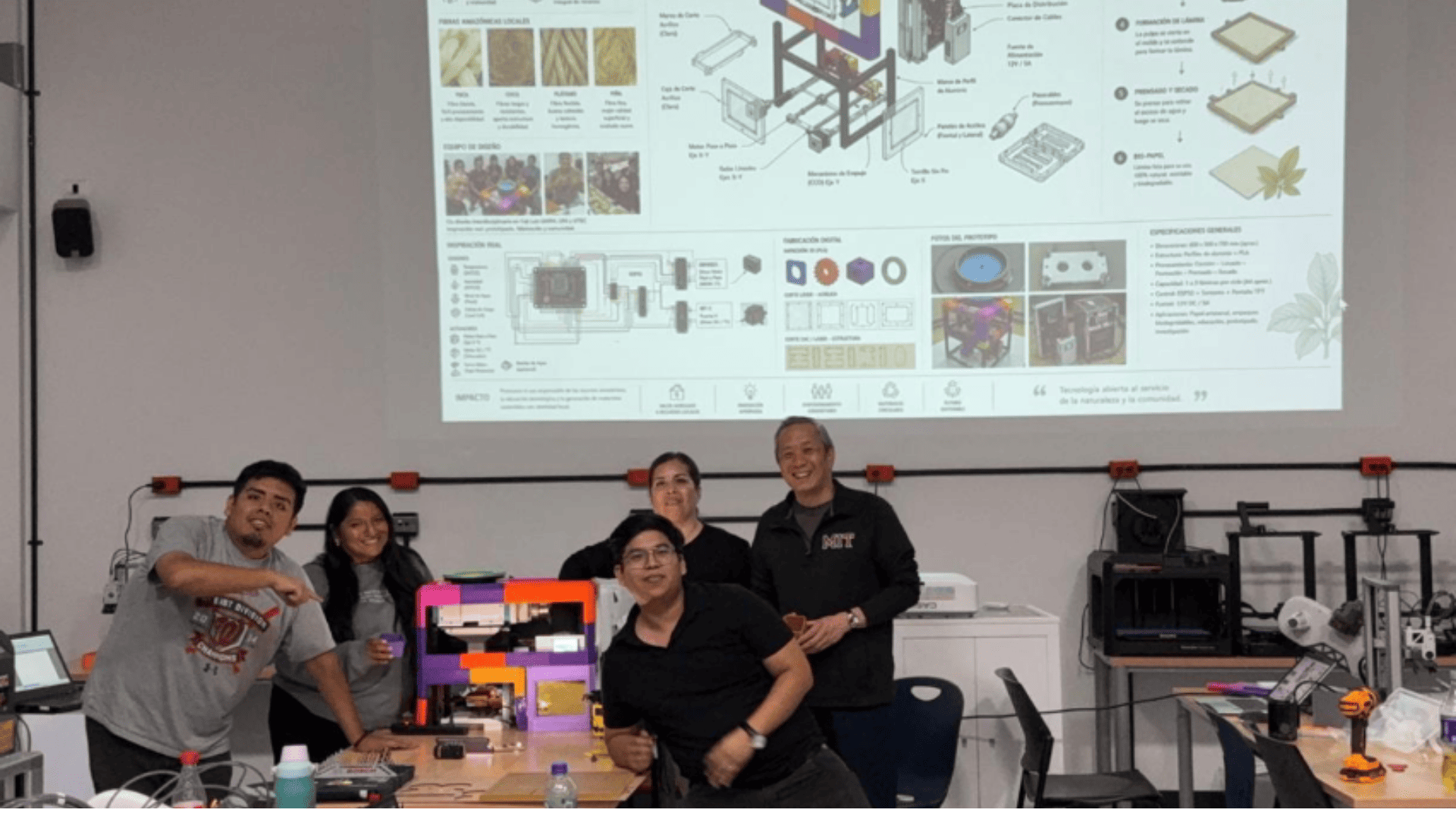
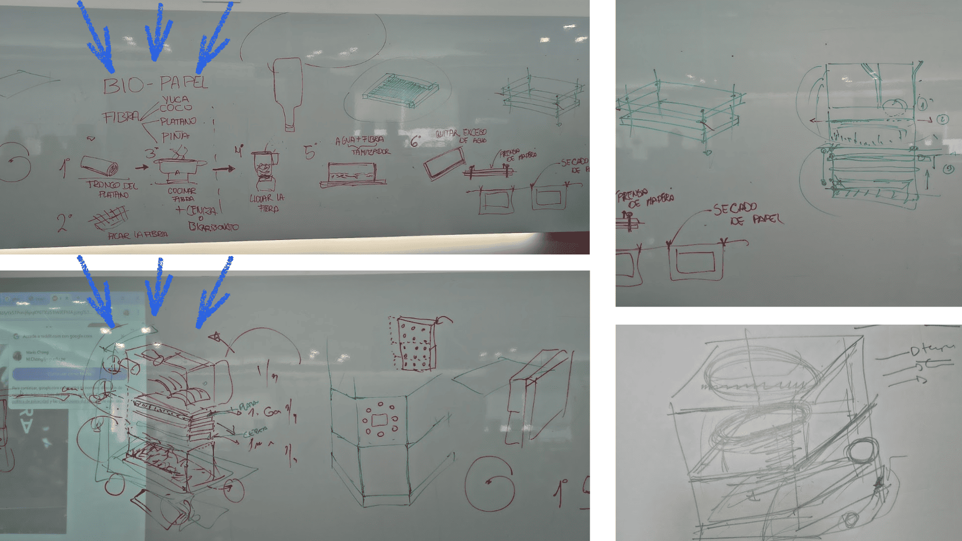
This phase defines the initial concept of the Smart Shredder, focused on producing Bio-Papel from organic waste. The workflow includes fibers such as banana trunk, yuca, coconut, and pineapple, ensuring the final pulp meets the requirements for sustainable paper fabrication.
Integrated Functional Requirements
- Harvesting the banana trunk
- Fiber chopping
- Cooking the fiber
- Blending the fiber
These stages define the mechanical requirements such as blade geometry and motor torque, aligning material research and machine design.
2. Mechanical Design and CAD Modeling
Single Unit Shredding Component
A modular cutting unit designed to efficiently shred organic fibers. Its aggressive external geometry allows cutting without clogging, while the internal profile aligns units into a rotating shaft.
Modular Blade Array
A matrix of 27 blades organized in a hexagonal shaft ensures uniform shredding. Designed in CAD to avoid interference and optimize fiber flow.
Main Cutting Chamber
The structural housing integrates motor mounts, bearings, and fiber input/output. Designed for durability and precise tolerances using CNC fabrication.
3. Digital Fabrication and Prototyping
3D Printing Preparation
CAD models are prepared in CAM software (Bambu Studio), defining supports, material (ABS/Nylon), and parameters for accurate prototyping.
Transmission Components
Custom gears are printed in ABS to test high-torque transmission, ensuring reliable power transfer from the motor to the shredding system.
4. Mechanical Integration and Assembly
Transmission System
The gearbox converts motor speed into high torque, integrating printed gears and mechanical shafts into a functional drive system.
Cutting System Assembly
Dual counter-rotating blade matrices are assembled and tested to ensure smooth operation and efficient fiber shredding without blockage.
5. Advanced Fabrication and Structural Assembly
Precision Transmission Mounts
Metal and polymer components ensure proper alignment and torque transmission, reducing friction and increasing efficiency.
Chassis Base Fabrication
A structural ABS base supports the motor and cutting system, fabricated using additive manufacturing with optimized parameters.
Main Chassis
The central structure integrates all mechanical components, forming the skeleton of the machine.
6. Power Drive System
The motor and gearbox system is fully integrated, converting high RPM into the torque required for shredding tough fibers efficiently.
7. Electronic Integration and Control
Custom PCB Design
A custom PCB (ESP32-based) controls the system, integrating sensors, motor drivers, and automation logic.
PCB Fabrication
CAM preparation and milling ensure precise electronic production for system control.
Control System Integration
The PCB manages motor behavior using drivers and sensor feedback, enabling automation.
8. Smart Fiber Processing
The shredded fiber is processed through a controlled cooking system using sensors for temperature regulation. This closes the loop between mechanical processing and biomaterial production.
fairs for entrepreneurs and artisans.Fab Lab ESAN
Advanced Mechanical Integration & Power Train
1. Torque Transmission & Cutting System
The power train begins with the CAM preparation of high-torque transmission components using FlatCAM. These parts are CNC-machined to ensure precise coupling between the motor and the shredding system, enabling efficient power transfer.
The core cutting system consists of two counter-rotating shafts with intermeshed blades, designed to maximize fiber processing efficiency. This assembly is supported by precision bearings and integrated into a reinforced cutting chamber.
2. Chassis Assembly and System Integration
A robust metal chassis provides structural stability, supporting the motor, gearbox, and cutting system. All components are securely mounted to ensure resistance to high mechanical stress during operation.
The system workflow connects shredding with the cooking process, incorporating temperature monitoring and automated control to maintain consistent biomaterial production.
3. Electronic Integration and Control
A custom PCB based on an ESP32 microcontroller acts as the central control unit. It integrates motor drivers, sensors, and power management to automate the shredding and processing workflow.
4. Programming and Automation
The system is programmed using Arduino IDE, enabling motor control, sensor monitoring, and automated sequences. Variable speed control and feedback loops allow the machine to adapt to different material conditions.
5. Power and Torque Monitoring
A dedicated sensor system monitors motor performance and torque in real time, ensuring efficient operation and preventing overload during fiber processing.
6. Final Integration and Validation
The complete system integrates mechanical, electronic, and control components into a functional prototype. The machine is validated through testing to ensure reliable shredding performance and consistent biomaterial output.
Collaborative Development and Personal Contribution
Concept Development and Project Ideation
From the early stages of the project, I actively participated in the conceptualization of the Smart Shredder, contributing to the definition of objectives, workflow design, and the connection between organic fiber processing and bio-paper production. Through brainstorming sessions and collaborative discussions, I helped transform initial concepts into feasible technical solutions.
Co-Creation and Team Collaboration
The machine was developed through a collaborative co-creation process involving all team members. My contribution included supporting design decisions, integrating mechanical and electronic solutions, and facilitating communication between different project stages to maintain a shared vision of the final product.
Digital Fabrication and Laser Cutting
As part of the digital fabrication process, I participated in the preparation and manufacturing of components using laser-cutting technology. This involved adapting CAD designs for fabrication, optimizing structural components, and validating parts before their integration into the machine.
Mechanical Assembly and System Integration
I contributed to the assembly and integration of the machine's mechanical, structural, and electronic components. This phase included testing component compatibility, making design adjustments, and ensuring the proper functionality of the complete system before operational testing.
Documentation and Presentation Board Development
I also contributed to the creation of the project's presentation board and technical documentation. This included organizing technical information, developing visual representations of the design and fabrication process, and communicating the evolution of the project from concept to functional prototype.
Group Meetings and Project Coordination
Throughout the development process, I actively participated in team meetings for planning, progress evaluation, and decision-making. These collaborative sessions enabled the team to solve technical challenges, distribute responsibilities, track project milestones, and ensure the successful integration of all project components.
Reflection on the Development Process
This project represented a continuous learning experience that combined research, design, digital fabrication, electronics, mechanical assembly, and teamwork. Through collaboration with my teammates, I was able to contribute to both the technical and organizational aspects of the Smart Shredder, helping transform an initial idea into a functional prototype for sustainable bio-paper production.
Video
Reflection
Initially, using RemoteXY and linking the Arduino (XIAO ESP32-C3) with the mobile application was a bit confusing. Setting up the connection, whether via Wi-Fi or Bluetooth, and understanding the generated code were the most challenging aspects.
It also took time to grasp how the interface created in the app relates to the variables within the code. However, through trial and error and continuous adjustments, I gradually gained a better understanding of the operation and communication between both environments.
Conclusion
Using RemoteXY allowed for the effective integration of Arduino with a mobile application, enabling real-time control of various components such as the RGB LED, the servo, and the OLED screen. This experience demonstrated how it is possible to develop interactive systems where the mobile device becomes a control interface.
Additionally, I reinforced my knowledge of programming, wireless connectivity, and IoT communication, understanding the importance of proper configuration and constant testing to achieve a stable and functional system.