Assignment Requirements
Group assignment
- Measure the power consumption of an output device.Send a message between two projects.
- Document your work to the group work page and reflect on your individual page what you learned.
Individual assignment
- design, build and connect wired or wireless node(s) with network or bus addresses and a local input and/or output device(s).
Progress Status
This is for reporting progress (not for visitors to click).
Group page link + notes added.
Missing final photos and conclusions.
Upload .zip with source files.
Assignment Requirements
Learning outcomes
- Demonstrate workflows used in network design.
- Implement and interpret networking protocols and/or communication protocols.
Have you answered these questions?
- Linked to the group assignment page.✅
- Documented your project and what you have learned from implementing networking and/or communication protocols.✅.
- Explained the programming process(es) you used.✅.
- Ensured and documented that your addressing for boards works.✅.
- Outlined problems and how you fixed them.✅.
- Included design files (or linked to where they are located if you are using a board you have designed and fabricated earlier) and original source code.✅.
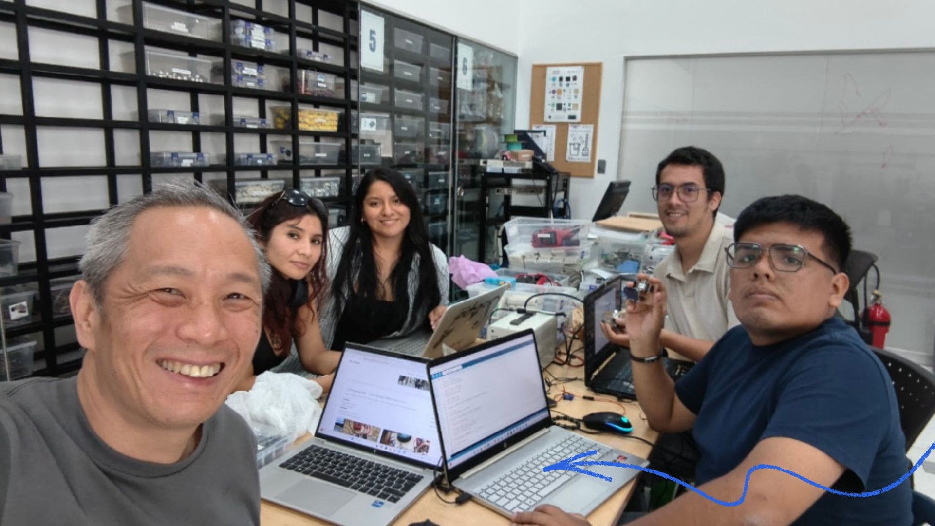
- Included a ‘hero shot’ of your network and/or communications setup.✅.
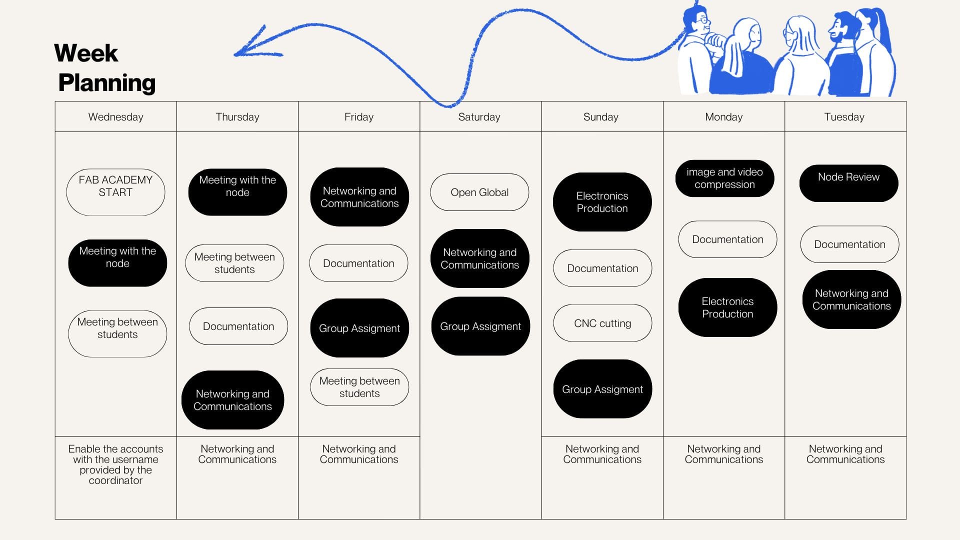
Weekly planning
During the week, we carried out various activities that presented significant challenges but were also very rewarding, especially due to the opportunity to share and learn as a team. We met virtually with our colleagues at the node and participated in lab meetings, which allowed us to organize ourselves and conduct open workshops in different spaces. In these sessions, we reviewed and worked with input devices, understanding their operation and their importance in capturing data from the environment for subsequent processing in electronic systems.
During Networking and Communications Week, we explored the fundamental principles of communication between electronic devices, a key aspect in the development of IoT (Internet of Things) systems. This week focused on understanding how different boards and systems can exchange information over networks using specific protocols such as MQTT.
Installation of MQTTX (MQTT client):
MQTTX was used, whose chat-based interface facilitates interaction and understanding of the data flow. This tool allows:
For more details about the group work and collaborative development, visit the following link:
Gruop Work- Networking and Communications Week
Problems
Diagnosis
Solutions
Tools Used
MQTT Server Configuration
More Information
View Group Documentation
Difficulties
During the group assignment, I was able to better understand how MQTT communication works between devices connected on the same local network. Through testing with the ESP32-C3, MQTTX, and the OLED display, I learned how data can be transmitted and visualized in real time using IoT communication protocols.
One of the main difficulties encountered was related to the micro servo, which did not respond correctly to the signals sent from another computer. This required additional testing, debugging, and adjustments in both the code and communication configuration to better understand the system behavior.
This experience helped me strengthen my knowledge of networking, hardware-software integration, and troubleshooting processes, while also reinforcing the importance of iterative testing to achieve stable and reliable communication between devices.
Video
Individual Assignment – Networking and Communications
In this assignment, the main objective was to explore networking and communication between electronic devices using the ESP32-C3 microcontroller. Different tests were carried out to understand how data can be transmitted, received, and visualized in real time through communication protocols and connected systems.
For these experiments, the PCB previously developed during the Electronics Production assignment was reused, allowing continuity with earlier work while expanding its functionality for networking and communication applications. This demonstrated that the same custom board can be adapted for multiple exercises and integrated into different interactive systems.
Additionally, several components such as OLED displays, sensors, and communication interfaces were tested to validate the behavior of the system and improve the interaction between hardware and software. These activities also contributed to the development of the final project and the mobile laboratory concept.
Components List (USD)
| # | Item Description | Qty | Unit | Unit Price (USD) | Total (USD) | Purchase Location |
|---|---|---|---|---|---|---|
| 1 | XIAO ESP32-C3 | 1 | UNIT | 16.22 | 16.22 | J6 Soluciones Tecnológicas |
| 2 | LCD Display 4x20 | 1 | UNIT | 5.41 | 5.41 | NYABBYCORP S.A.C |
| 3 | OLED Display 0.96 (4 pins) | 1 | UNIT | 5.14 | 5.14 | NYABBYCORP S.A.C |
| 4 | SMD Resistor 1206 (1K ohm) | 30 | PCS | 0.27 | 8.11 | NYABBYCORP S.A.C |
| 5 | Male Header 40 pins | 10 | UNIT | 0.27 | 2.70 | NYABBYCORP S.A.C |
| 6 | Female Header 40 pins | 10 | UNIT | 0.27 | 2.70 | NYABBYCORP S.A.C |
| 7 | Solder Wick 1.5 mm | 1 | UNIT | 1.89 | 1.89 | NYABBYCORP S.A.C |
| 8 | DHT11 Module | 2 | UNIT | 2.16 | 4.32 | NYABBYCORP S.A.C |
| TOTAL | $59.73 USD | |||||
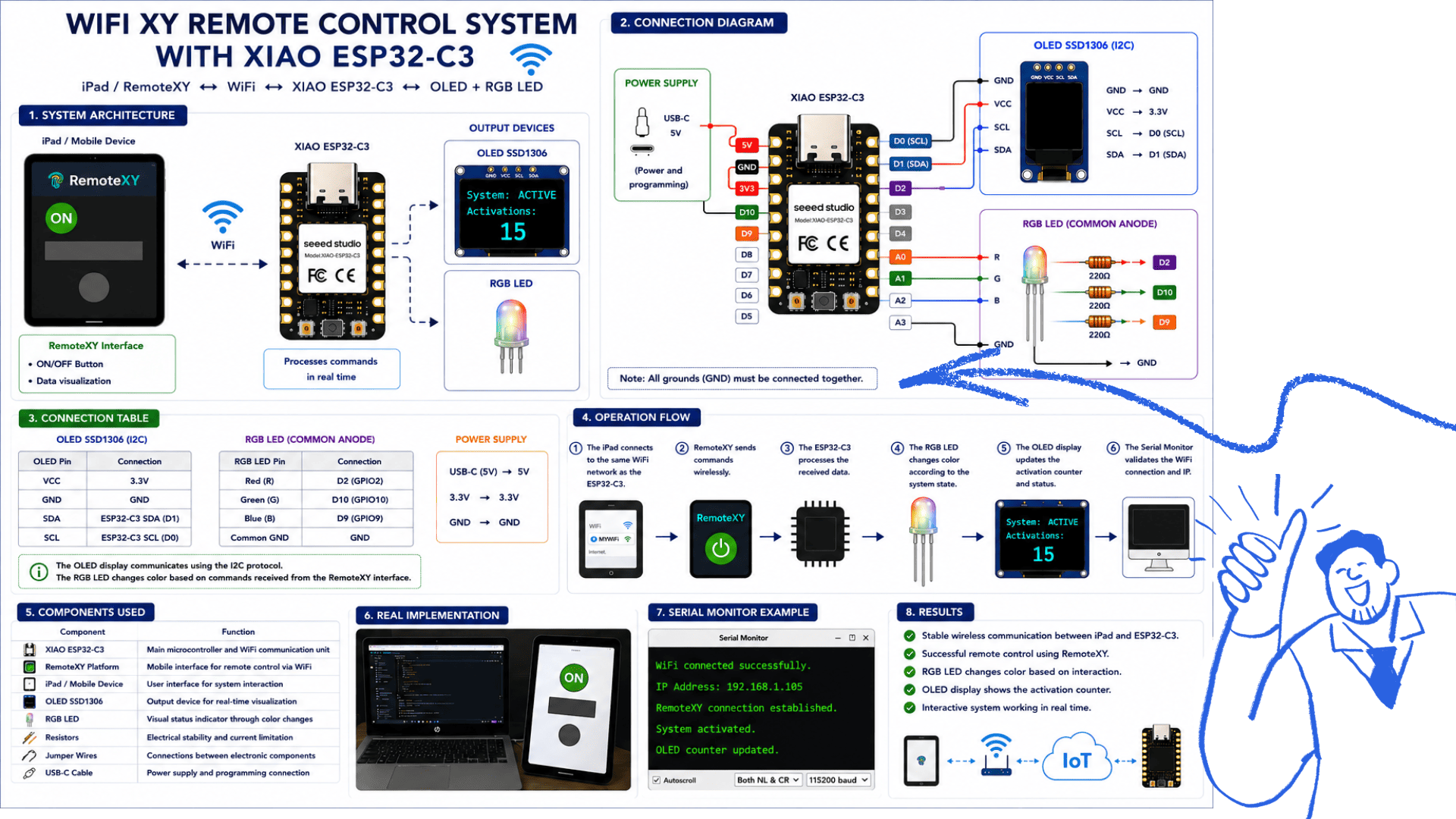
RemoteXY WiFi Control with XIAO ESP32-C3
1. Introduction
In this exercise, RemoteXY was used to develop a remote control interface for a mobile device (in this case, an iPad), allowing interaction with a XIAO ESP32-C3 board via a WiFi connection. The programming was done in the Arduino IDE, integrating different electronic components to achieve a real-time interactive system.
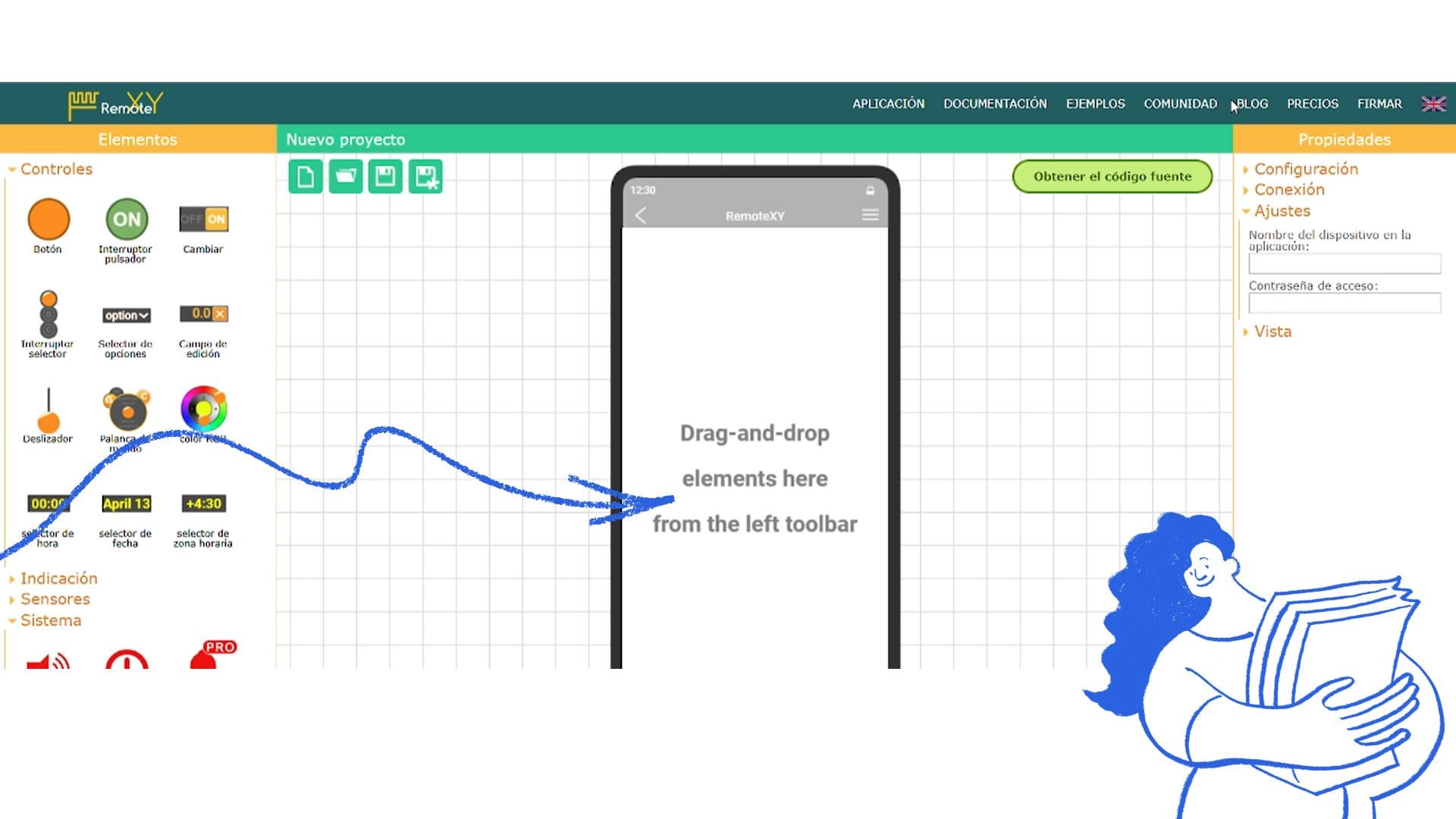
2. Creating the Interface in RemoteXY
- Go to: https://remotexy.com
- Access the Online Editor.
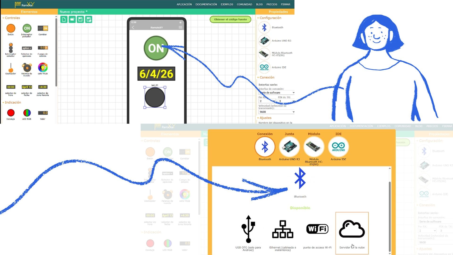
- Design the interface by adding:
- An ON/OFF button to control the system.
- A data display field (status or information from the board).
- Configure the connection type as WiFi.
- Select the board: ESP32 (compatible with XIAO ESP32-C3).
- Click on “Get Source Code” and copy the generated code.
3. Configuration in Arduino IDE
- Open the Arduino IDE.
- Install the RemoteXY library from the Library Manager.
- Select the board: XIAO ESP32-C3.
- Paste the code generated by RemoteXY.
- Configure the WiFi network settings:
#define REMOTEXY_WIFI_SSID "YOUR_WIFI"
#define REMOTEXY_WIFI_PASSWORD "YOUR_PASSWORD"
4. Hardware Integration
During the project development, the following components were integrated:
- OLED display: used to show the number of times the system was activated (power-on counter).
- RGB LED (3 colors): used to visualize state changes based on interaction from the iPad.
These components improved the visualization of the system behavior in real time.
5. Uploading the Program
- Connect the XIAO ESP32-C3 to the computer.
- Select the correct port.
- Upload the code.
- Open the Serial Monitor to verify the connection and obtain the device's IP address.
6. Connecting from the iPad
- Ensure the iPad is connected to the same WiFi network.
- Open the RemoteXY app or a web browser.
- Enter the IP address shown in the Serial Monitor.
- View the interface (ON/OFF button and data display).
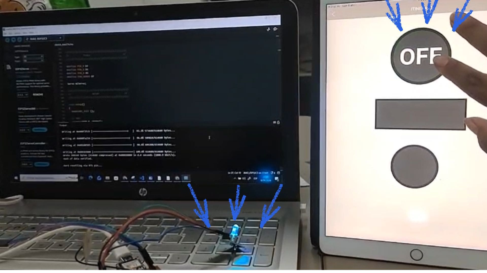
7. Functionality Test
- Press the ON button on the iPad.
- Verify system response:
- The RGB LED changes color.
- The OLED screen updates the activation count.
- Confirm real-time communication via WiFi.
8. Results
Effective wireless communication was established between the iPad and the XIAO ESP32-C3 via WiFi. The integration of RemoteXY, the OLED display, and the RGB LED enabled the creation of an interactive system, demonstrating successful integration of hardware, software, and IoT communication.
Components Used
| Component | Function |
|---|---|
| XIAO ESP32-C3 | Main microcontroller and WiFi communication unit |
| RemoteXY Platform | Mobile interface for remote control via WiFi |
| iPad / Mobile Device | User interface for system interaction |
| OLED SSD1306 | Output device for real-time visualization |
| RGB LED | Visual status indicator through color changes |
| Resistors | Electrical stability and current limitation |
| Jumper Wires | Connections between electronic components |
| USB-C Cable | Power supply and programming connection |
Component Connections
OLED SSD1306 Display (Output Device)
The OLED SSD1306 display was used to visualize the system status and the activation counter in real time.
| OLED Pin | Connection |
|---|---|
| VCC | 3.3V |
| GND | GND |
| SDA | ESP32-C3 SDA |
| SCL | ESP32-C3 SCL |
Communication between the OLED display and the XIAO ESP32-C3 was established using the I2C protocol.
RGB LED (Output Device)
The RGB LED was integrated to provide visual feedback according to the system state controlled from the mobile device.
| RGB LED Pin | Connection |
|---|---|
| Red | GPIO Pin |
| Green | GPIO Pin |
| Blue | GPIO Pin |
| Common GND | GND |
The RGB LED changes color depending on the commands received through the RemoteXY interface.
General System Operation
- The iPad connects to the same WiFi network as the XIAO ESP32-C3.
- The RemoteXY interface sends commands wirelessly.
- The ESP32-C3 processes the received data in real time.
- The RGB LED changes color according to the system state.
- The OLED display updates the activation counter and status information.
- The Serial Monitor validates the WiFi communication and device IP address.
Output Device Functionality
The OLED display and the RGB LED function as the main output devices of the system.
The OLED screen provides real-time visual information such as activation counts and system states, while the RGB LED offers immediate visual feedback through color changes triggered from the mobile interface.
This integration demonstrates how wireless communication and output devices can be combined to create interactive IoT systems using the XIAO ESP32-C3 and RemoteXY.
System Validation
The complete system was tested to validate communication between the iPad, the RemoteXY interface, the XIAO ESP32-C3, and the output devices.
During testing:
- The iPad successfully connected to the ESP32-C3 via WiFi.
- The RemoteXY interface responded correctly in real time.
- The RGB LED changed colors according to user interaction.
- The OLED display updated the activation counter correctly.
- The system maintained stable wireless communication.
Serial Monitor Output
WiFi connected successfully.
IP Address: 192.168.1.105
RemoteXY connection established.
System activated.
OLED counter updated.
These tests validated the correct operation of the wireless communication system and confirmed the successful integration of hardware, software, and IoT interaction.
 WITH XIAO ESP32-C3
The RemoteXY interface was configured directly from the web platform by accessing the online editor, where the control elements such as buttons and data displays were added visually. Then, the WiFi connection mode and the ESP32 board were selected, allowing the platform to automatically generate the source code used later in the Arduino IDE for communication with the XIAO ESP32-C3.
The RemoteXY interface was configured from the online editor according to the project requirements and the previous programming already developed for the custom ESP32-C3 PCB. Different interface elements such as buttons, status displays, and control options were added to interact with the system in real time.
During the configuration process, the connection type was selected depending on the communication method required for the project, such as WiFi or Bluetooth. In this case, WiFi communication was used to allow wireless interaction between the mobile device and the XIAO ESP32-C3 through the Arduino IDE environment.
After defining the interface characteristics, RemoteXY automatically generated the source code, which was later integrated into Arduino IDE together with the previous programming developed for the PCB, enabling communication, visualization, and remote control of the system.
Video
A clear correlation can be observed between the programming developed in Arduino IDE and the RemoteXY platform, since both work together to establish communication between the mobile device and the custom ESP32-C3 PCB through a WiFi connection. Using the generated interface, it was possible to verify the program operation remotely by activating functions from a tablet or smartphone.
Through this communication, the RGB LED could be turned on and controlled wirelessly, while the OLED display simultaneously showed system information and status updates in real time. This demonstrated the correct integration between software, hardware, wireless communication, and interface visualization.
Additionally, this exercise maintains continuity with the final project proposal, since it explores how environmental information, remote interaction, and connected devices can be integrated into the mobile laboratory system using IoT communication technologies.
Video
Reflection
Initially, using RemoteXY and linking the Arduino (XIAO ESP32-C3) with the mobile application was a bit confusing. Setting up the connection, whether via Wi-Fi or Bluetooth, and understanding the generated code were the most challenging aspects.
It also took time to grasp how the interface created in the app relates to the variables within the code. However, through trial and error and continuous adjustments, I gradually gained a better understanding of the operation and communication between both environments.
Conclusion
Using RemoteXY allowed for the effective integration of Arduino with a mobile application, enabling real-time control of various components such as the RGB LED, the servo, and the OLED screen. This experience demonstrated how it is possible to develop interactive systems where the mobile device becomes a control interface.
Additionally, I reinforced my knowledge of programming, wireless connectivity, and IoT communication, understanding the importance of proper configuration and constant testing to achieve a stable and functional system.