Assignment Requirements
Group assignment
- Complete your lab's safety training
- Test runout, alignment, fixturing, speeds, feeds, materials and toolpaths for your machine
- Document your work to the group work page and reflect on your individual page what you learned
Individual assignment
- Make (design+mill+assemble) something big
Progress Status
This is for reporting progress (not for visitors to click).
Group page link + notes added.
Missing final photos and conclusions.
Upload .zip with source files.
Assignment Requirements
Learning outcomes
- Demonstrate 2D design development for CNC milling production
- Describe workflows and operation for large format CNC machining
Have you answered these questions?
- Linked to the group assignment page✅
- Reflected on your individual page what you learned of your labs safety training✅.
- Documented how you designed your object and made your CAM-toolpath✅.
- Documented how you milled and assembled your final product (including setting up the machine, fixturing, feeds, speeds etc.)✅.
- Described problems and how you fixed them✅.
- Included your design files and 'hero shot' of your final product✅.
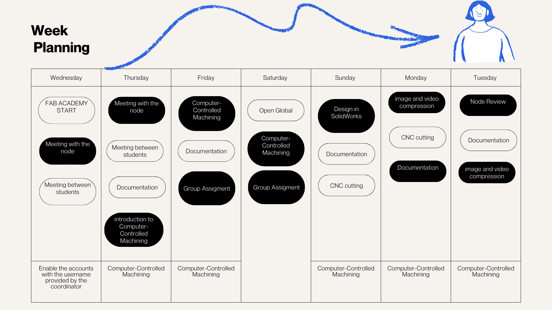
Weekly planning
During the week, we carried out various activities that presented significant challenges but were also very rewarding, especially due to the opportunity to share and learn together. We met virtually with our colleagues in the node and also participated in Open Lab meetings with Iquitos, Satipo, and Lima, which allowed us to organize and conduct open workshops in the different labs. In these sessions, we were able to review the software necessary for the work, as well as the machines, materials, and instruments required for each activity. This experience strengthened coordination between nodes and allowed us to better understand the importance of planning and managing resources effectively in digital fabrication processes.
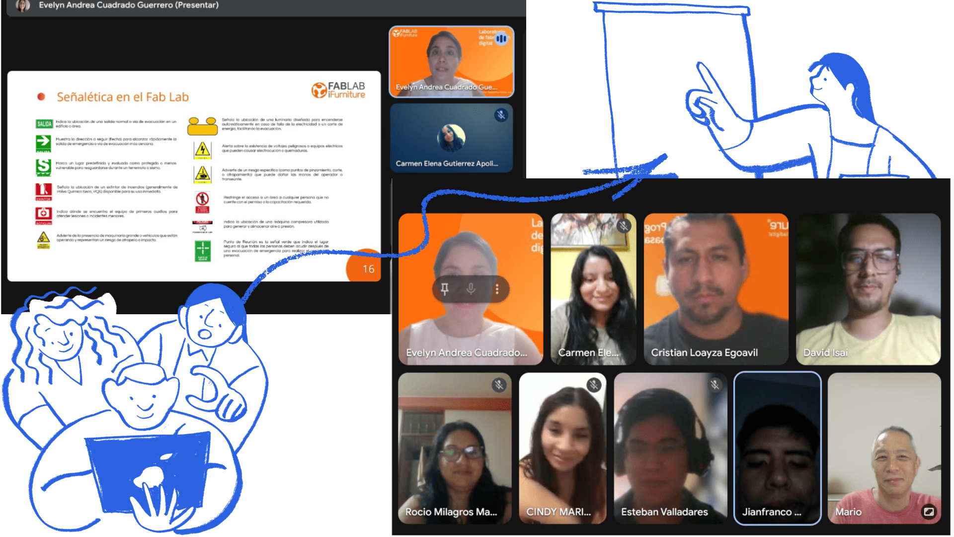
Introduction to Computer-Controlled Machining
The topic of Computer-Controlled Machining was new to me and the other members of my group. Thanks to the support of Evelyn Cuadrado, we were able to better understand the initial concepts. She provided us with a clear introduction, a practical example, and support in using the program, which facilitated our learning and allowed us to move forward with greater confidence this week. In addition, Cristian Loayza helped us with the laboratory safety talk, explaining the main safety rules and recommendations for the correct use of the machines and tools in the Fab Lab.
Group Work
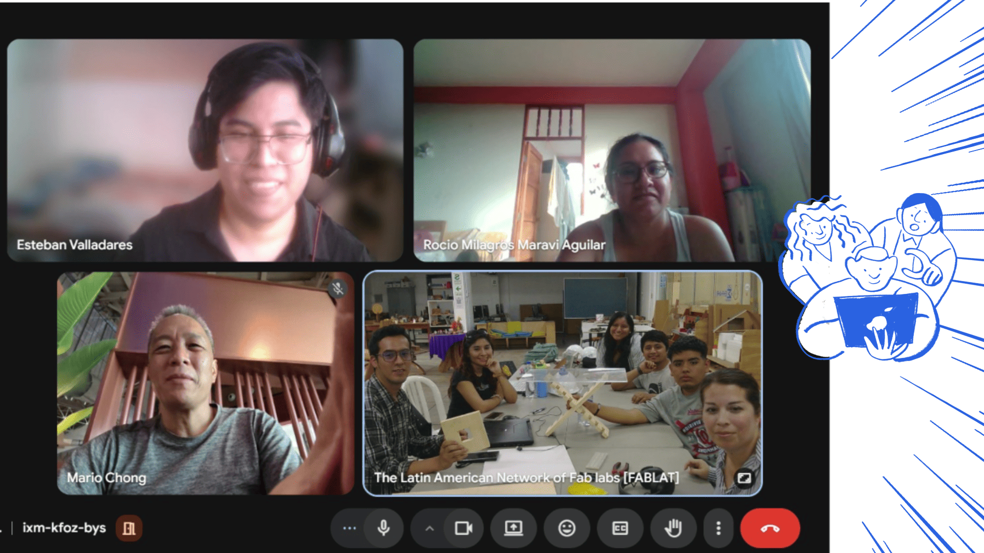
This week we focused on Computer-Controlled Machining using a large-format CNC router. As a group, we began with a virtual meeting where we analyzed the weekly requirements and organized our activities. During this session, we also shared information about the machines available in each lab, which allowed us to understand the different capabilities and define the tests we could perform based on available resources.
It was a valuable experience, as the variety of machines and configurations gave us the opportunity to compare results, analyze differences in performance, and better understand how technical characteristics influence digital manufacturing processes.
We also started with a safety training session, reviewing the proper use of personal protective equipment (PPE), emergency procedures, workspace conditions, and machine safety zones. After that, we worked collaboratively to understand the CNC workflow, including tool installation, material setup, machine zeroing, board fixation, calibration, and machining execution.
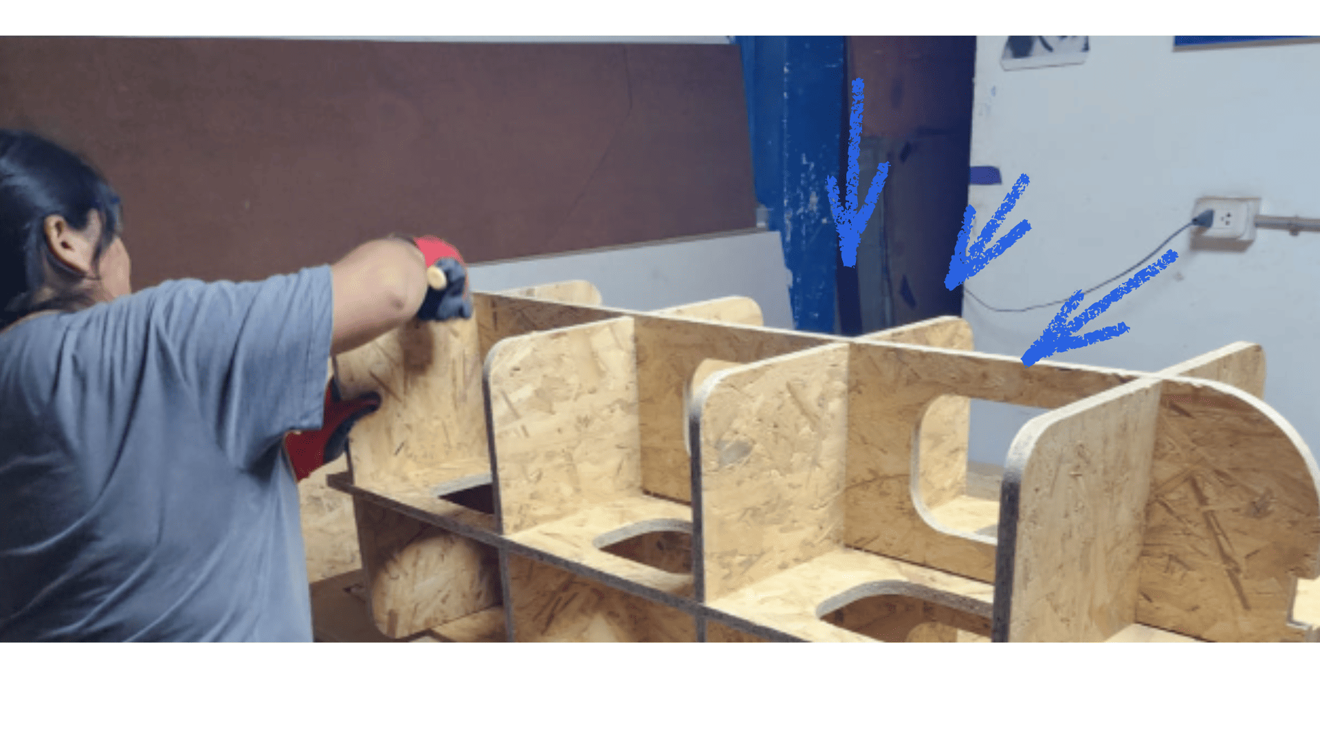
To evaluate machining quality and press-fit behavior, we produced two test pieces: a square test and a comb test. These allowed us to analyze fit tolerance, internal corners, tabs, dogbones, material response, and how parameters such as feed rate, spindle speed, and pass depth affect the final result.
For more details about the group work, visit the group page .
Personal Reflection
Through this group assignment, I realized that large-format CNC machining involves much more than simply sending a file to the machine. From my perspective, the process requires careful preparation, awareness of safety protocols, proper machine setup, and a clear understanding of material behavior.
Working with the group helped me understand that safety starts even before operating the machine, and that toolpath simulation is essential to avoid errors. I also learned how critical it is to correctly set the machine zero, and how recalibration may be necessary after fixing the material to ensure precision.
Additionally, I gained a deeper understanding of how feeds, speeds, and cutting depth directly influence the quality of the cut and the performance of the tool. The press-fit tests, such as the comb test, allowed me to better understand tolerances and how joints behave in real conditions.
I also observed the importance of design details like dogbones to improve internal fits, and how material properties, such as plywood roughness, can affect the final result and require post-processing.
Personal Conclusion
From this experience, I can conclude that CNC machining is a process that integrates digital design with physical execution, where every parameter and decision has a direct impact on the final outcome.
Participating in this group assignment allowed me to strengthen my understanding of machine operation, material behavior, and safety practices. It also highlighted the importance of testing, such as square and comb tests, to validate designs before applying them to real projects.
Overall, this experience has given me a more complete and practical vision of digital fabrication, which will be very valuable for future CNC-based projects.
Individual Task
Create (Design + Milling + Assembly) Something Big
This was one of the tasks that allowed me to solidify some ideas based on real-world experiences we have observed. From a design perspective, I wanted to find a way to support artisans and entrepreneurs who participate in fairs to offer their products.
They generally use tables to display their products, but these tables are often solid, heavy, and difficult to transport. In addition, they do not always allow the products to be displayed clearly and attractively.
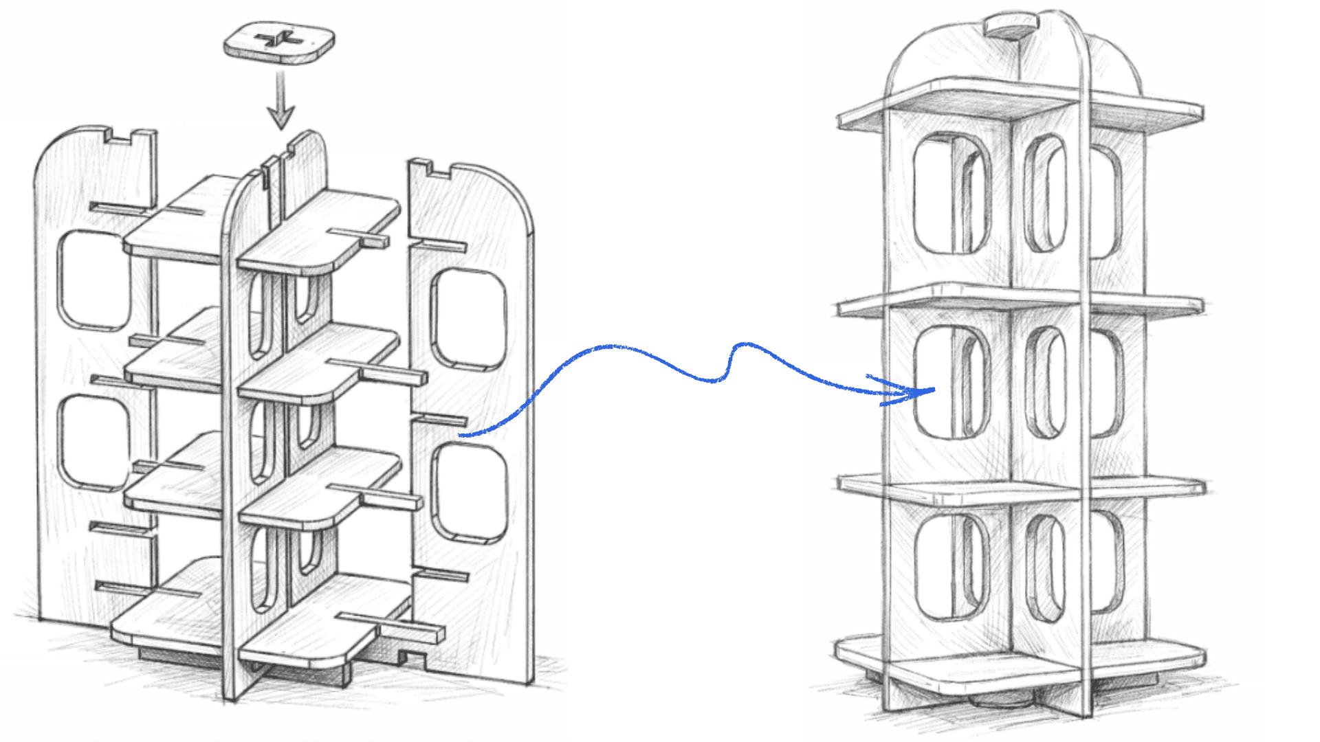
For this reason, I proposed the design of a product display that is easy to assemble and disassemble. The idea was to create a system with a simple structure that allows it to be transported easily to different fairs.
This design is intended to be assembled without the use of bolts or screws, using only a press-fit system, which allows the pieces to be joined through friction and precise fitting.
The goal is to continue developing this concept of mobile furniture that responds to the realities of artisans and entrepreneurs who constantly travel to different parts of Peru. Just as the Fab Lab promotes digital fabrication in different spaces, artisans could also take these displays to different places and organize traveling fairs anywhere.
Using a simple, portable, and functional piece of furniture can help improve the presentation of their products and support better sales opportunities during fairs and exhibitions.
fairs for entrepreneurs and artisans.
Concept and Proposal
Before beginning the digital design, I reflected on the type of object I wanted to create, how it should function, and who would use it. My goal was to design a structure that was functional, stable, safe, and easy to assemble.
First, I created a sketch to visualize the overall shape, the pieces, and the structure of the display. This initial step helped me better organize the idea and understand how the different elements could fit together before moving on to the digital design.
fairs for entrepreneurs and artisans.
Design in SolidWorks
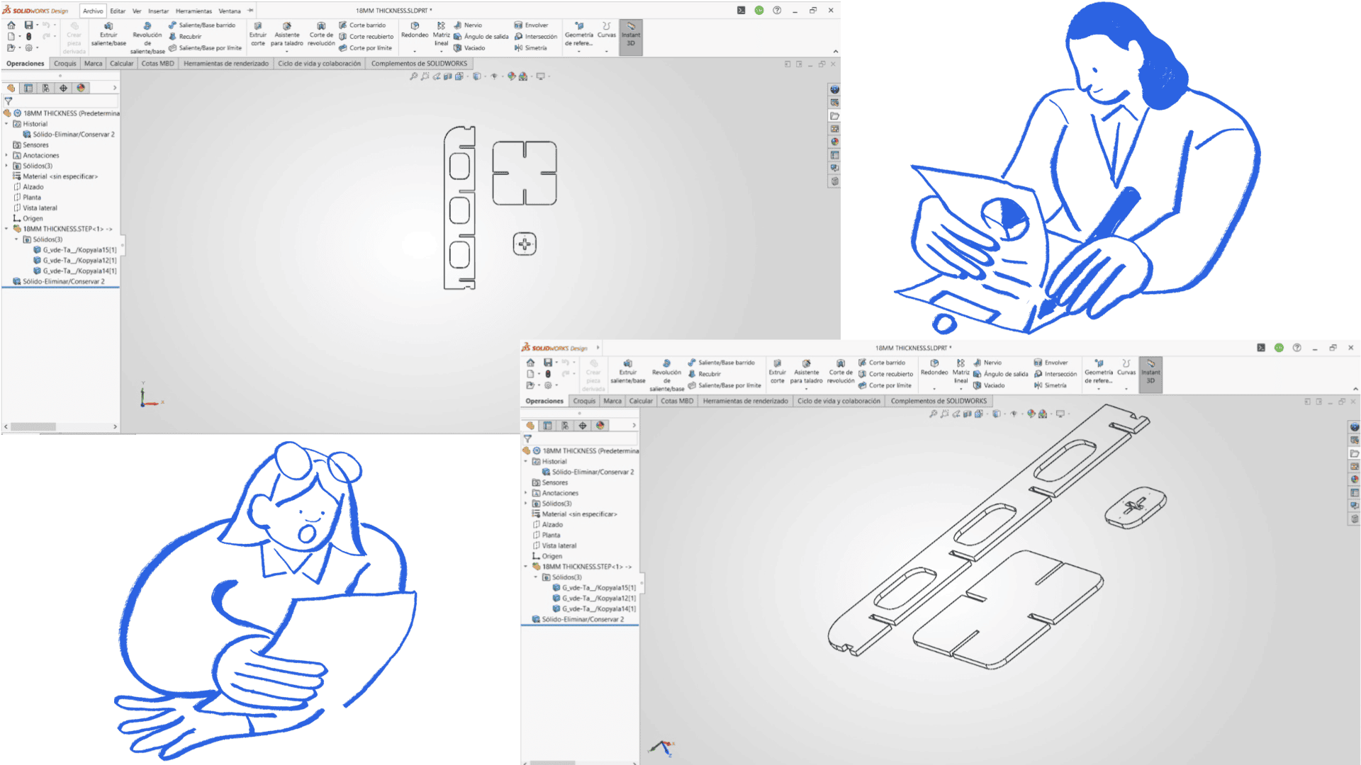
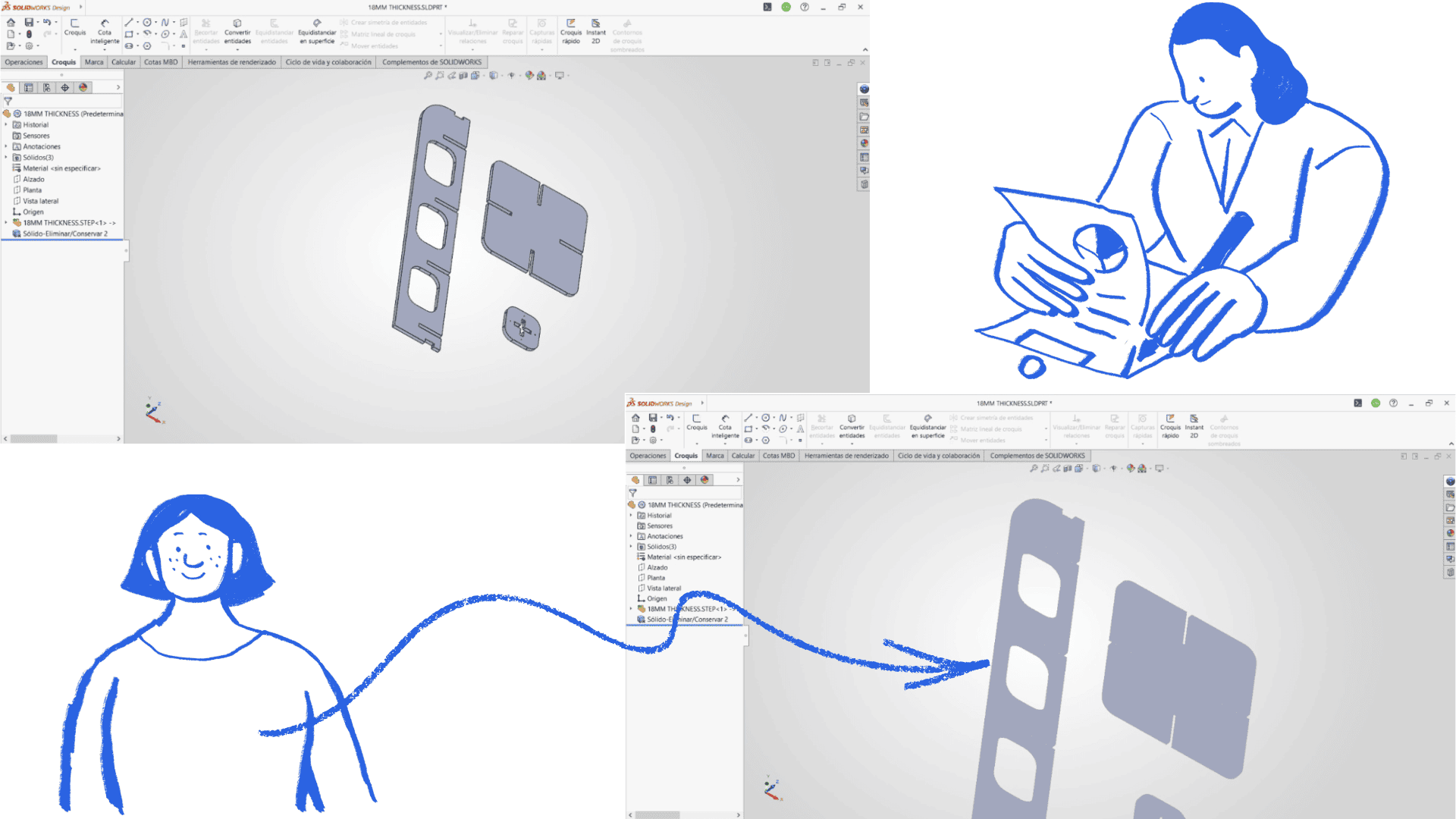
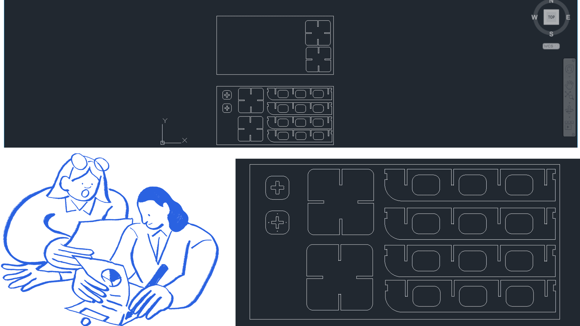
Starting with the initial sketch, I began developing the design in SolidWorks. I started working on the plan view to define the main dimensions and the layout of the structure, and then moved on to the 3D model to visualize how the different pieces would be joined.
During the 3D modeling, I was able to analyze the connections between the pieces, the joints, the gaps, and the angles necessary for the products to be displayed properly. This process was important to ensure that the structure was stable and functional.
The design process was not simple, as it was necessary to consider several factors, such as material thickness, material type, finishes, press-fit joints, and the assembly system. All of these aspects were important to ensure that the final design could be manufactured correctly using the CNC cutting process.
Design in SolidWorks.
Design in SolidWorks.
Design in SolidWorks.
Machining with Aspire
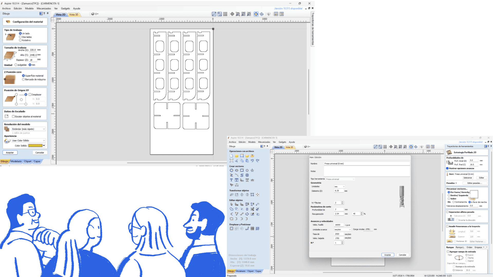
To prepare for machining, we open a new file in the software and locate our .DXF file, previously exported from the design program. This file is imported into Vectric Aspire and adjusted to the format and dimensions of the cutting area. Next, we establish the machine origin points, which will serve as a reference for machining.
Once the design is loaded, we select all the vectors we wish to machine and use the Profile Toolpath option. At this stage, we choose the cutting tool, in this case a 6 mm milling cutter, and configure the machining parameters such as depth of cut, feed rate, and spindle speed. After defining these parameters, we confirm the operation so that the software generates the machining toolpath.
Before performing the actual cut, we run a simulation of the toolpath to verify that there are no errors and to ensure that all parts will be cut correctly. Once the process is validated, we export the machining file in G-code.
For this process, we use the NC Studio post-processor in millimeters (.tap) and save the generated toolpath for use on the CNC machine.
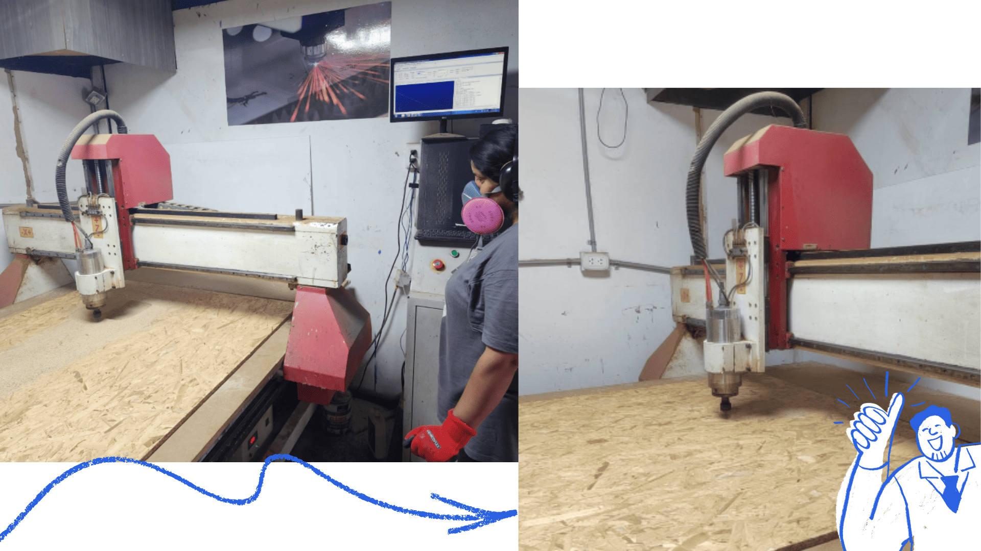
CNC Milling
Next, we open the NC Studio software and load the file containing the generated code. We place the OSB board on the machine bed and secure it firmly with screws to prevent any movement during the cutting process.
We then position the tool and set the origin of the X, Y, and Z axes (machine zero) to ensure the machining is performed in the correct position.
Once the cutting process is complete, we carefully remove the pieces. We then proceed with the assembly, using a rubber mallet to fit the pieces together through the press-fit system. This step must be done carefully to avoid damaging the edges of the material and to ensure that the joints are firm and properly fitted.
During the machining process, we used Vectric Aspire software to import the .DXF file and configure the work area according to the material dimensions. We then selected the vectors to be cut and generated the toolpath using a 6 mm milling cutter, configuring parameters such as spindle speed, feed rate, and depth of cut.
Next, we performed a machining simulation to verify that the toolpaths were correct and to avoid errors during cutting. Finally, we exported the file in .tap format, compatible with NC Studio, to generate the G-code and perform the CNC milling on the machine.
To prepare for machining, we opened a new project in
Vectric Aspire and imported the .DXF file previously exported from the design software.
The file was adjusted to the dimensions of the CNC machine working area, and the material setup was configured according to the size of the OSB board used for machining.
Next, we defined the machine origin point for the X, Y, and Z axes. This reference point is essential to ensure that the machining process is performed in the correct position on the material.
After importing the design, we selected all vectors to be machined and used the Profile Toolpath option to generate the cutting paths. We selected a 6 mm end mill and configured the machining parameters as follows:
- Spindle Speed: 16,000 rpm
- Feed Rate: 2,500 mm/min
- Depth per Pass: 7 mm
In Aspire, we also configured the cutting strategy, defining internal and external cuts, machining direction, and the number of passes required depending on the material thickness.
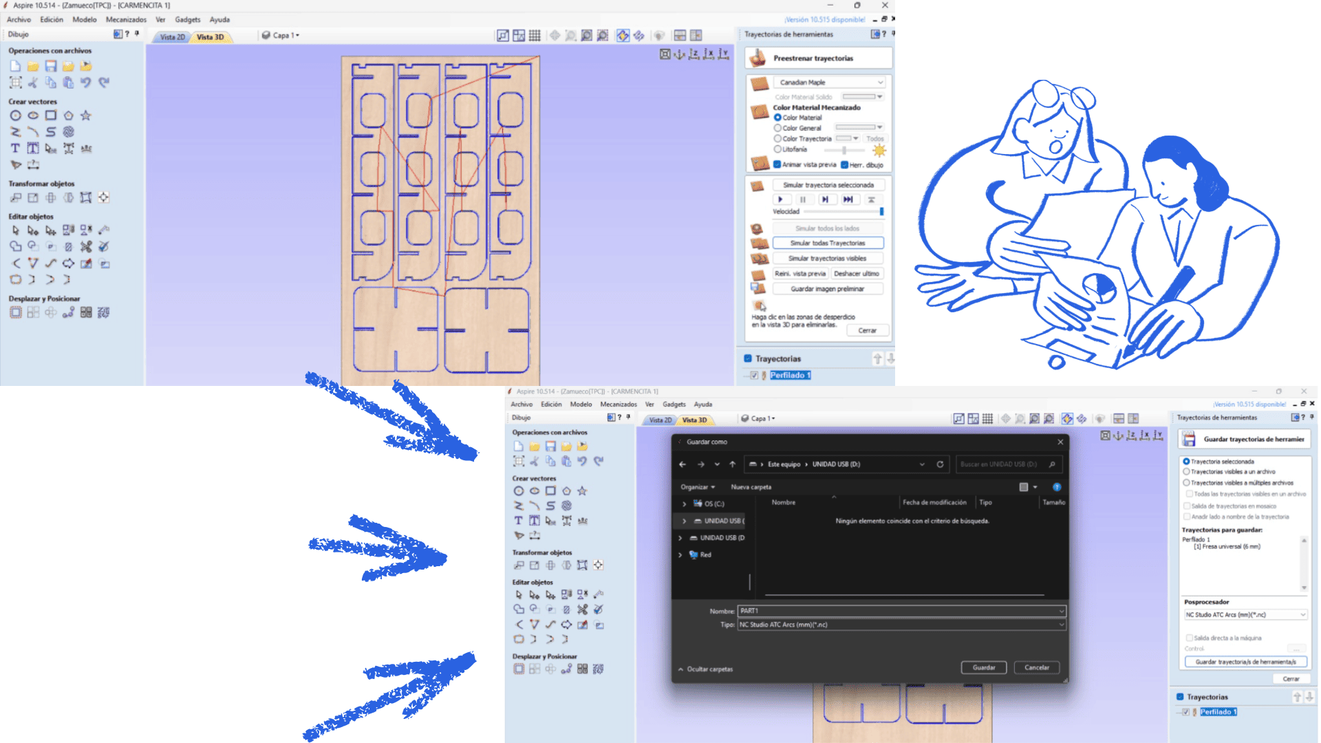
Once all parameters were configured, we clicked “Calculate” to automatically generate the toolpaths. These toolpaths represent the exact movement that the milling cutter will follow during machining.
Before starting the real cutting process, we used Aspire’s simulation feature to verify the machining process and detect possible errors. This simulation helped us confirm that all parts fit correctly and that there were no incomplete cuts or collisions.
Finally, we exported the file using the NC Studio post-processor in millimeters (.tap), generating the G-code file compatible with the CNC machine.
Toolpath and G-Code Generation
After configuring all machining operations, Aspire automatically generated the toolpaths required for the CNC milling process. These toolpaths visually represent the exact route that the cutting tool follows during machining.
The final machining file was exported in .tap format, which contains the G-code instructions used to control the CNC machine.
The file includes commands for:
- Tool positioning
- Feed rate control
- Spindle activation and deactivation
- Cutting depth configuration
- Machining sequence execution
Once exported, the file was loaded into NC Studio, where the toolpaths were visually verified before starting the machining process. This verification ensured that the generated paths matched the original design correctly.
CNC Milling
To begin the CNC milling process, we opened the NC Studio software and loaded the previously generated G-code file. The OSB board was then placed on the CNC machine bed and firmly secured using screws to prevent movement during cutting.
Next, we manually positioned the tool and configured the zero point for the X, Y, and Z axes. Setting the machine origin correctly is essential to ensure accurate machining according to the digital design.
Once the origin point was established, the CNC milling operation was started. During machining, we continuously monitored the machine, the cutting tool behavior, and the material stability to guarantee a safe and precise process.
After machining was completed, the cut parts were carefully removed from the machine bed and post-processing tasks were performed, including:
- Removing holding tabs
- Cleaning dust and machining residue
- Sanding the edges to improve surface finish
- Checking the fit and assembly of the machined parts
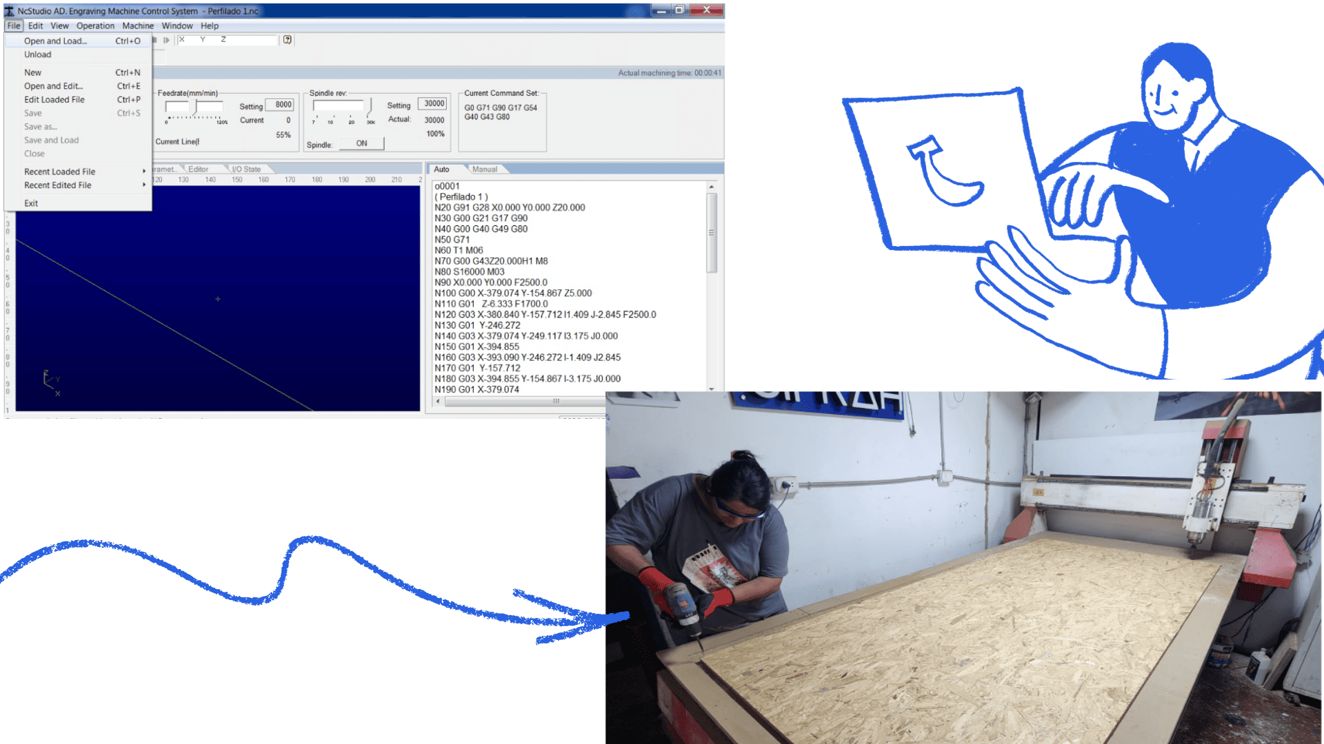
We will place the OSB board on the CNC machine bed and secure it firmly with screws to prevent movement during machining. Next, we will position the cutting tool and set the zero origin point on the X, Y, and Z axes, ensuring that the milling process is performed accurately and in the correct location on the material.
Once the workpiece was correctly positioned and the origin point set, we pressed the "Start" button to begin CNC machining. The process took approximately 40 minutes, as the cut was made in three passes to ensure greater precision and safety during milling. After machining was complete, we carefully removed the cut pieces from the OSB board and performed a general cleaning of the work area.
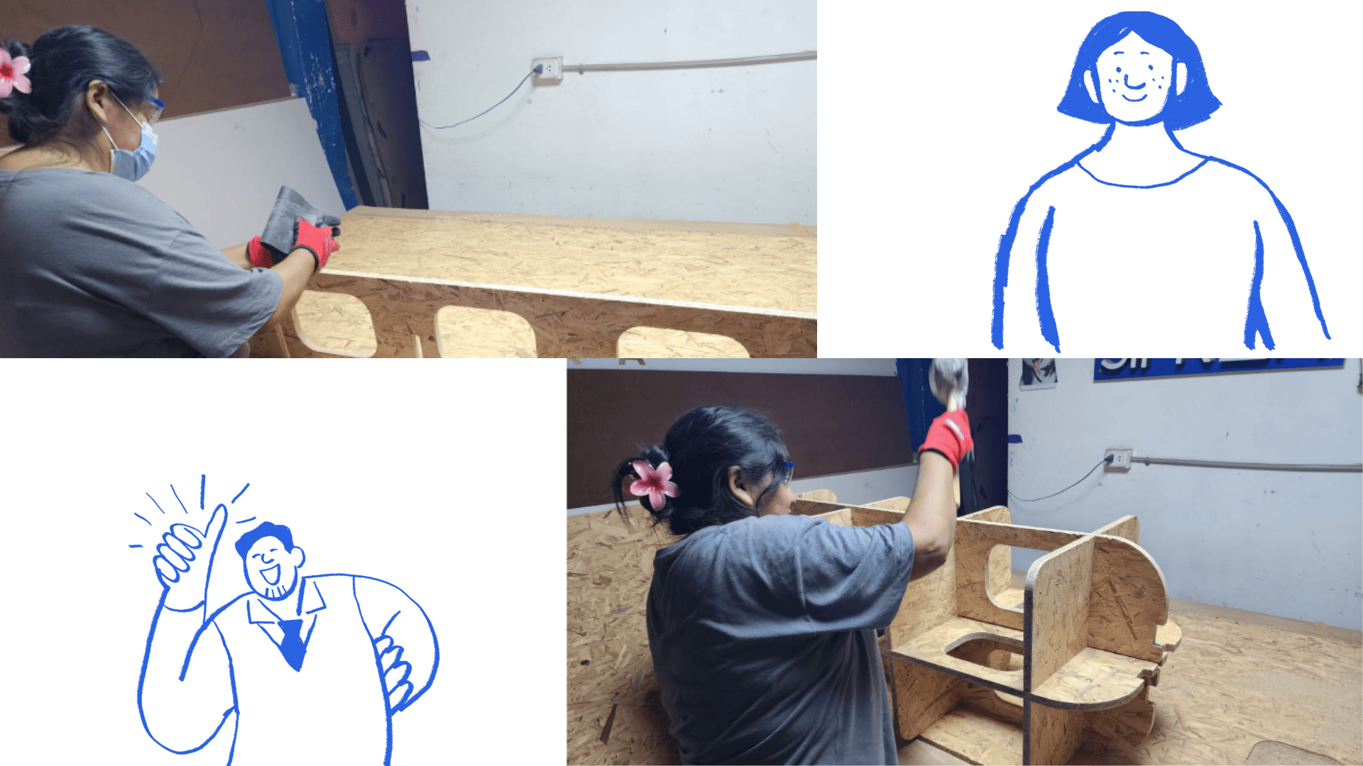
After machining, we sanded both sides of the cut edges using 80-grit wet sandpaper to improve the surface finish and remove imperfections created during cutting. We then assembled the pieces using a rubber mallet to ensure a proper fit. This process was carried out carefully to avoid damaging the edges and to guarantee a precise fit between all the machined parts.
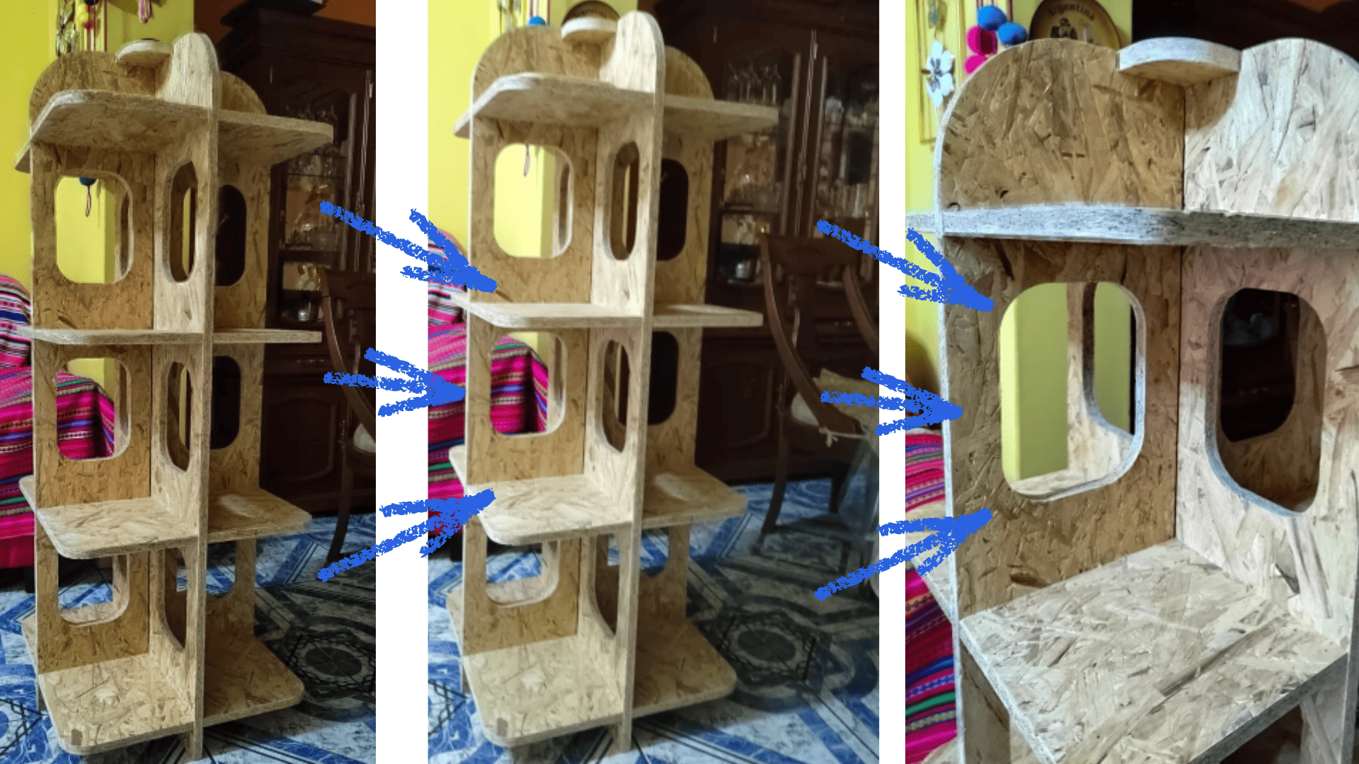
Finally, we have the fully assembled piece of furniture, with all the parts correctly fitted and adjusted. The final result demonstrates the precision of CNC machining and the importance of correctly configuring the cutting paths and parameters throughout the entire manufacturing process.
AI Usage Evidence
Prompt Used
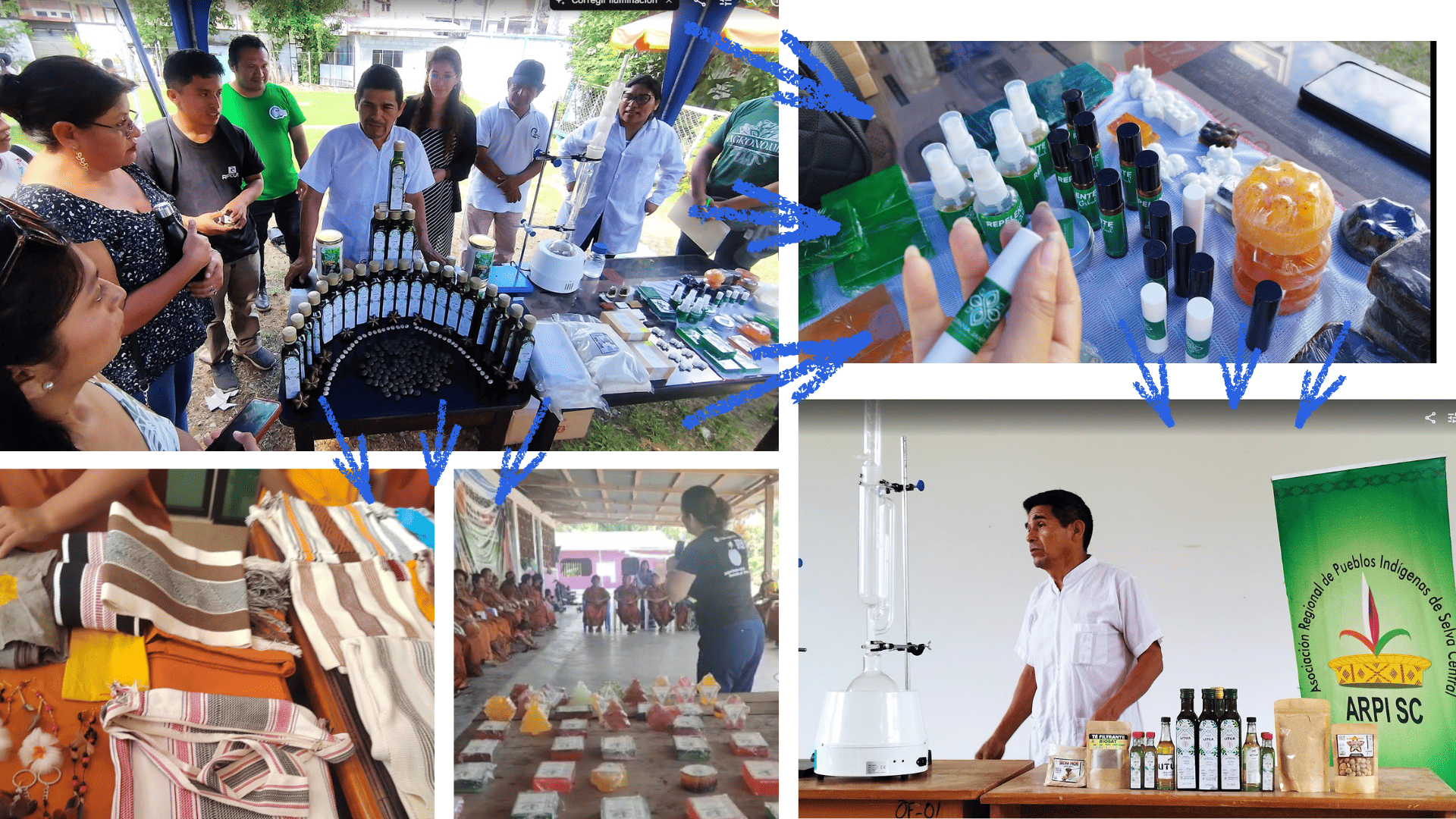
Using the provided image of a wooden modular furniture design, generate a realistic scene where the furniture is placed in a cultural context. Add handcrafted artisanal objects such as baskets, textiles, and traditional decorations made from natural fibers.

Include people from a native community interacting naturally with the furniture, wearing traditional clothing and accessories. The environment should feel authentic, warm, and representative of a local market or community space.

Ensure the furniture remains the central element, while the added elements enhance its cultural use and context. Maintain realistic lighting, proportions, and textures.
Generated Results
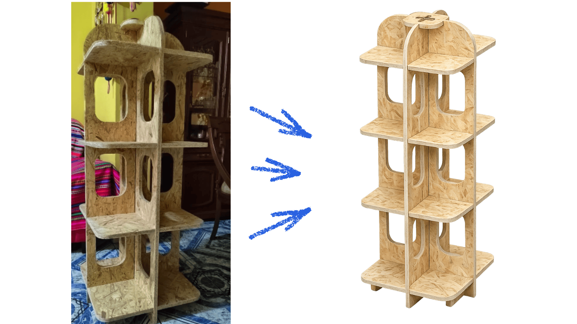
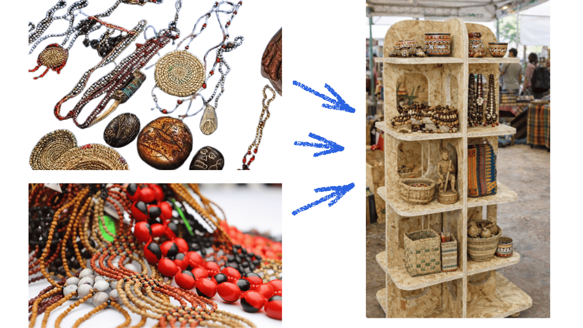
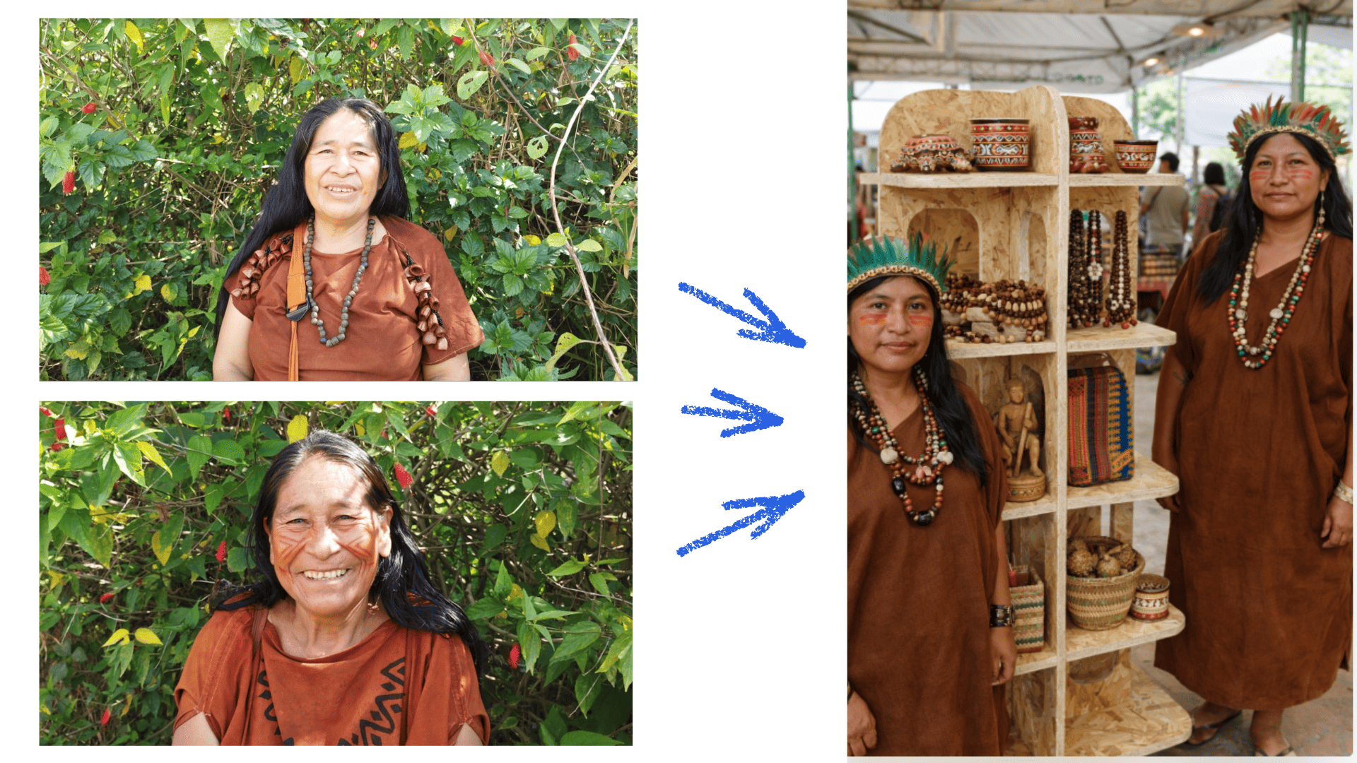
Final Combined Visualization
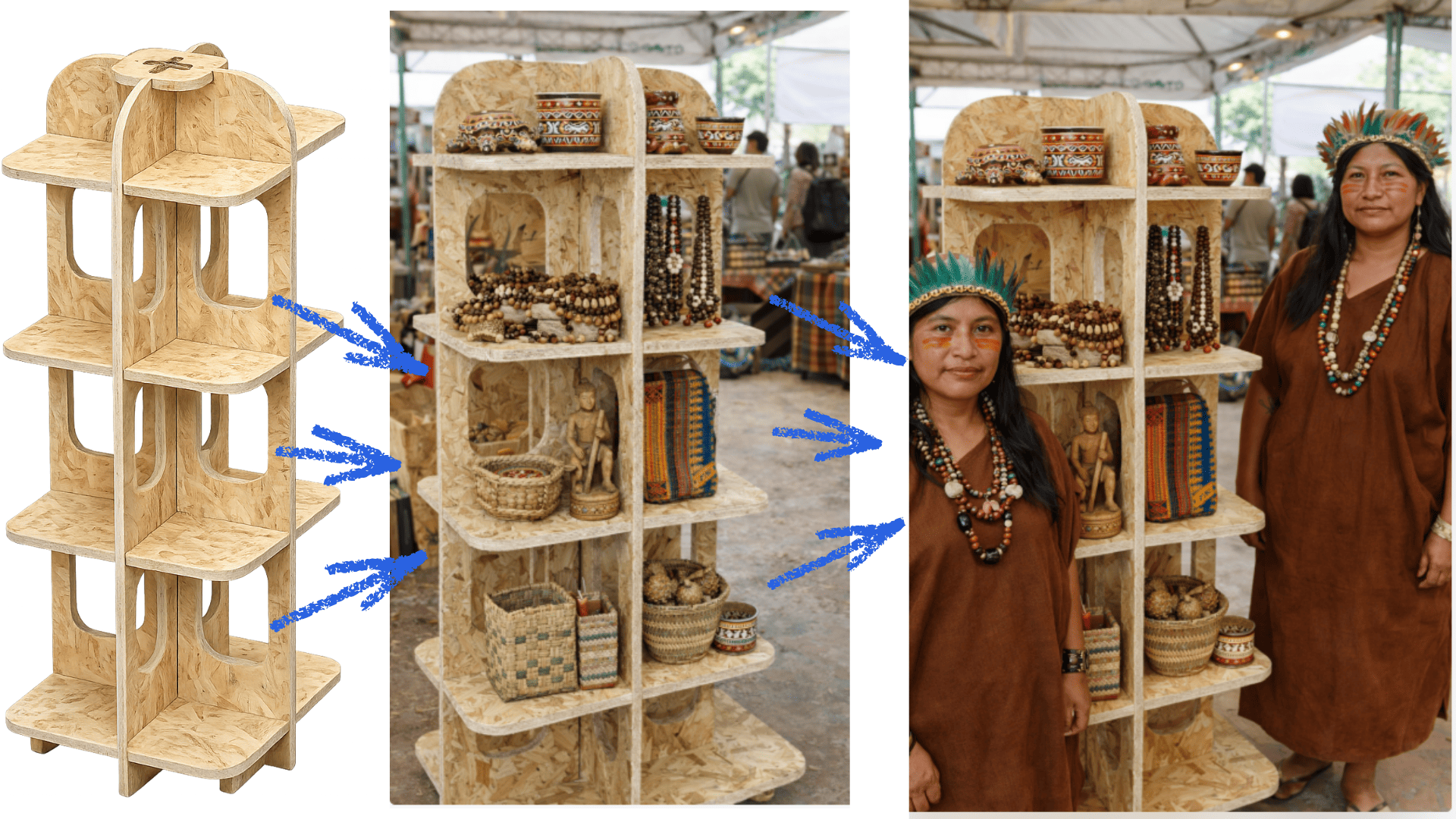
These images illustrate the process from the original design to its contextualization using Artificial Intelligence. The final visualization helps communicate how the furniture can be integrated into a real cultural environment, strengthening the narrative and impact of the project.
Conclusions
During this activity, I was able to understand and apply different stages of the digital manufacturing process using CNC. First, I learned to design a 2D CNC cutting project using Corel Draw, which allowed me to correctly prepare the vectors necessary for machining.
I also learned to configure and generate machining toolpaths in Vectric Aspire, defining important parameters such as the cutting tool, depth of cut, feed rate, and spindle speed. This step was fundamental to ensuring that the digital design could be correctly transformed into machine instructions.
Furthermore, I gained experience operating a CNC milling machine, understanding the material preparation process, table clamping, setting the reference axes (X, Y, and Z), and performing the cut safely.
Another important lesson was understanding the importance of planning and organization throughout the entire design and machining process. Good planning allows for optimizing material usage, reducing cutting time, and preventing errors during manufacturing.
Ultimately, this experience allowed me to better understand the relationship between digital design and physical manufacturing, as well as the importance of considering aspects such as material thickness, press-fit joints, and the assembly process from the design stage. These lessons will be very useful for the development of future digital fabrication projects.