Assignment Requirements
Group assignment
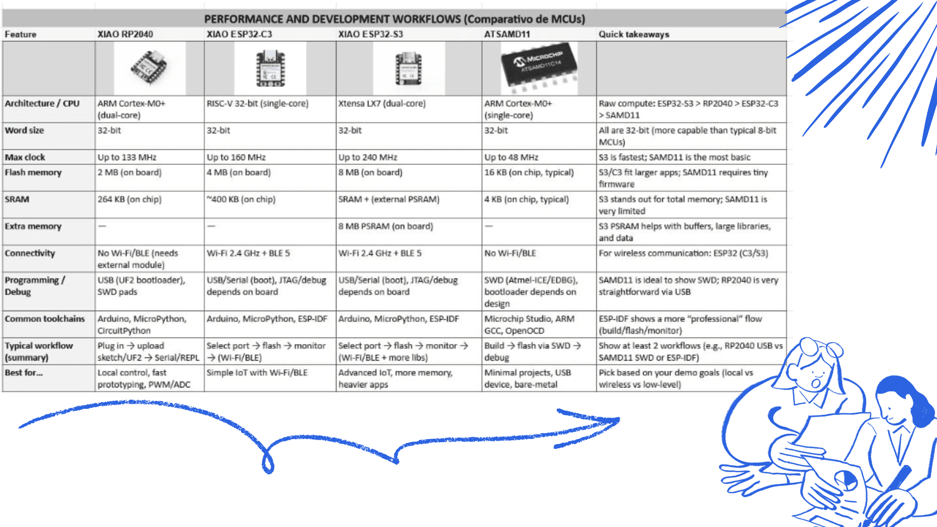
- Demonstrate and compare the toolchains and development workflows for available embedded architectures
- Document your work to the group work page and reflect on your individual page what you learned
Individual assignment
- Browse through the datasheet for a microcontroller
- CWrite and test a program for an embedded system using a microcontroller to interact (with local input &/or output devices) and communicate (with remote wired or wireless connections)
Group assignment
Group assignment
Progress Status
This is for reporting progress (not for visitors to click).
Group page link + notes added.
Missing final photos and conclusions.
Upload .zip with source files.
Assignment Requirements
Learning outcomes
- Implement programming protocols..
Have you answered these questions?
- Linked to the group assignment page✅
- Browsed and documented some information from a microcontroller's datasheet✅.
- Programmed a board to interact and communicate✅.
- Described the programming process(es) you used✅.
- Included your source code✅.
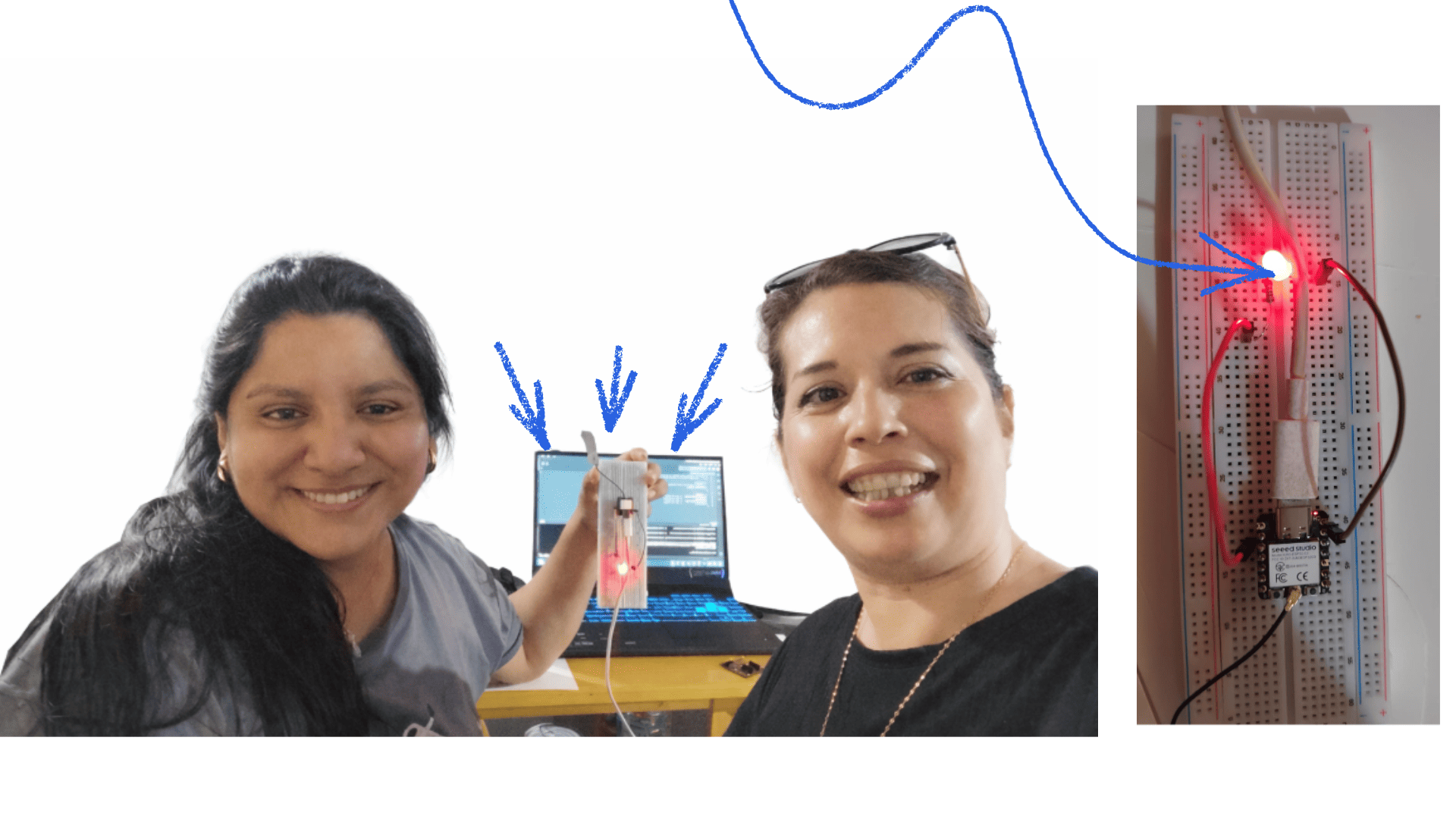
- Included ‘hero shot(s)’✅.
Introduction to Embedded Programming
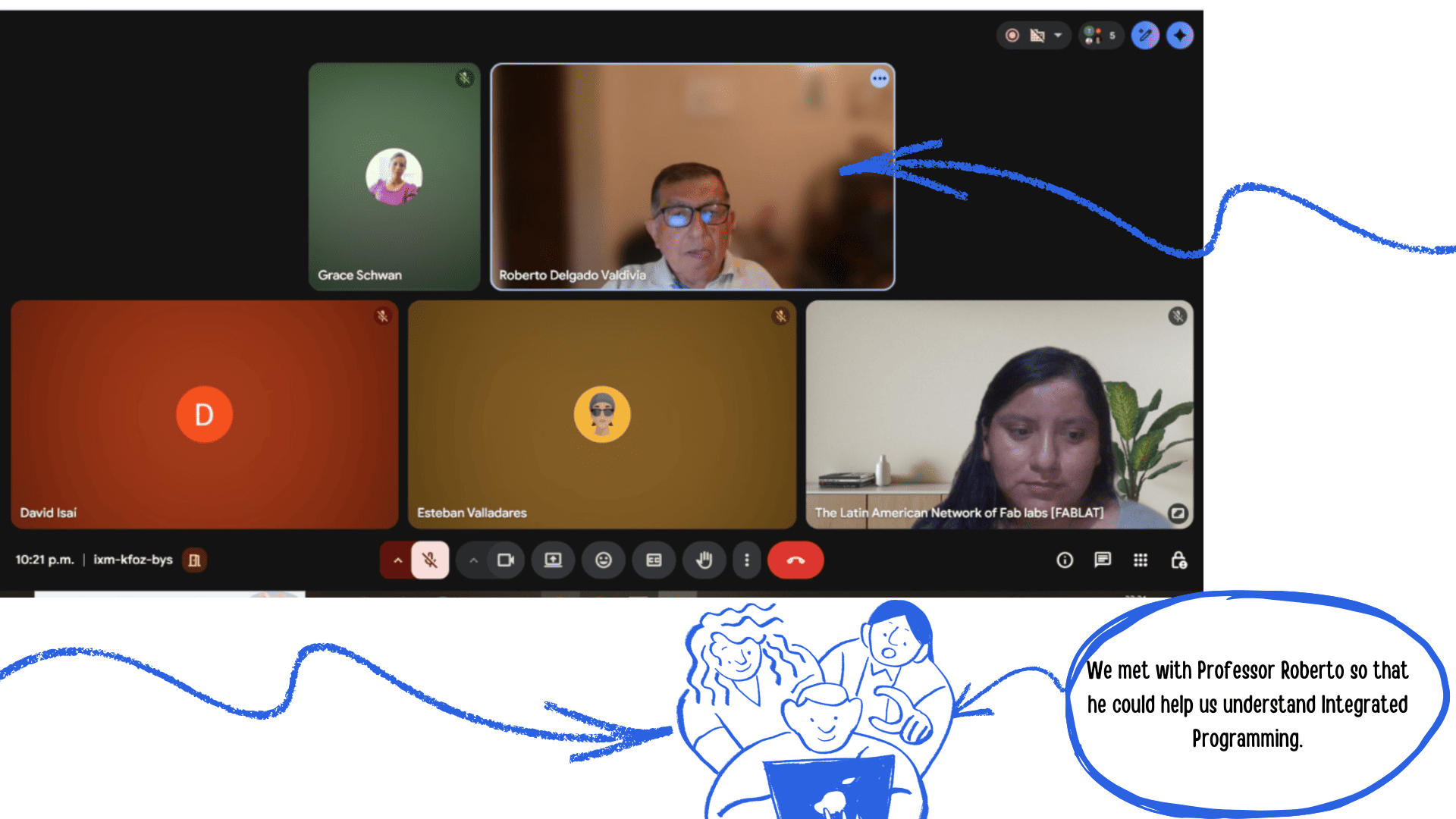
Esta semana también estuvo llena de retos. Pudimos reunirnos virtualmente con el maestro Roberto , del nodo, quien nos brindó una orientación más clara sobre el tema que debíamos abordar durante la semana. Gracias a su guía, comprendimos que el trabajo estaba dividido en una parte grupal y otra individual, lo que implicó una mejor organización y distribución de tareas.
Group work
During Week 4, which focused on Embedded Programming, my colleague
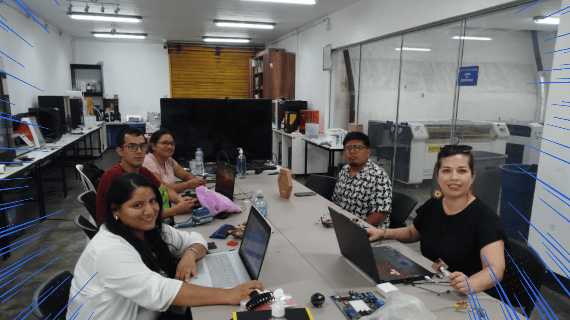
During Week 4, which focused on Embedded Programming, my colleague Grace Schwan and the team organized ourselves to demonstrate and compare toolchains and development workflows across different microcontroller families. To better distribute the workload, each team member focused on a specific microcontroller.
In my case, I documented the operation and development environment of the ESP32-C3, while my colleague worked with the RP2040. Afterward, we shared our findings with the team to analyze and compare them with other selected architectures, allowing us to identify similarities, differences, and advantages of each platform.
Compare performance and development workflows for other architecteurs
1) Comparison of other architectures
For this comparison, we used four different families (XIAO form factor + one “minimal” ARM option):
- RP2040 (ARM Cortex-M0+ dual-core, 32-bit)
- ESP32-C3 (RISC-V, 32-bit, Wi-Fi/BLE)
- ESP32-S3 (Xtensa LX7 dual-core, 32-bit, Wi-Fi/BLE)
- ATSAMD11 (sometimes written “ATAMD11”) (ARM Cortex-M0+, 32-bit)
Quick comparison of performance and capabilities (hardware)
| MCU/Board | CPU / Architecture | Max clock | Memory (board/chip) | Connectivity | Typical use |
|---|---|---|---|---|---|
| RP2040 | Dual-core ARM Cortex-M0+ | 133 MHz | 264 KB SRAM + 2 MB Flash | No wireless | Local control, PWM/ADC/PIO, fast prototyping |
| ESP32-C3 | RISC-V 32-bit (single-core) | 160 MHz | 400 KB SRAM + 4 MB Flash | Wi-Fi + BLE 5 | Basic IoT, connectivity, low cost |
| ESP32-S3 | Xtensa LX7 dual-core 32-bit | 240 MHz | 8 MB PSRAM + 8 MB Flash | Wi-Fi + BLE 5 | IoT + heavier apps / light edge-AI |
| ATSAMD11 | ARM Cortex-M0+ 32-bit | 48 MHz | 16 KB Flash + 4 KB SRAM | No wireless | Minimalist, USB device, simple control, low power |
Toolchains and Workflow Comparison
| MCU/Board | Common toolchains | How it’s programmed (typical workflow) | Evidence to show |
|---|---|---|---|
| RP2040 | Arduino / MicroPython / CircuitPython | USB upload (UF2/IDE) + Serial Monitor/REPL | Upload screenshot + Serial logs + LED/button demo |
| ESP32-C3 | Arduino / MicroPython / (optional ESP-IDF) | Flash via USB-serial (ROM bootloader) + serial monitor | Flash logs + Wi-Fi/BLE connection + remote demo |
| ESP32-S3 | Arduino / MicroPython / (optional ESP-IDF) | Flash via USB + monitor; ideal for Wi-Fi/BLE demos and larger apps | Logs + Wi-Fi/BLE demo + power modes/consumption (if applicable) |
| ATSAMD11 | gcc-arm / Microchip Studio + OpenOCD/EDBG/Atmel-ICE (SWD) | Build (ARM GCC) → program/debug via SWD | Terminal/IDE commands screenshot + programmer photo + USB/Serial output |
2) Comparison of other architectures
This week we compared four microcontrollers/boards: RP2040, ESP32-C3, ESP32-S3, and ATSAMD11. The main differences between them are processing power, memory, connectivity, and the programming workflow they typically use.
Performance and Development Workflows (MCU Comparison)
| Feature | RP2040 | ESP32-C3 | ESP32-S3 | ATSAMD11 | Quick takeaways |
|---|---|---|---|---|---|
| Architecture / CPU | ARM Cortex-M0+ (dual-core) | RISC-V 32-bit (single-core) | Xtensa LX7 (dual-core) | ARM Cortex-M0+ (single-core) | Raw compute: ESP32-S3 > RP2040 ≈ ESP32-C3 > SAMD11 |
| Word size | 32-bit | 32-bit | 32-bit | 32-bit | All are 32-bit (more capable than typical 8-bit MCUs) |
| Max clock | Up to 133 MHz | Up to 160 MHz | Up to 240 MHz | Up to 48 MHz | S3 is fastest; SAMD11 is the most basic |
| Flash memory | 2 MB (on board) | 4 MB (on board) | 8 MB (on board) | 16 KB (on chip, typical) | S3/C3 fit larger apps; SAMD11 requires tiny firmware |
| SRAM | 264 KB (on chip) | ~400 KB (on chip) | SRAM + external PSRAM | 4 KB (on chip, typical) | S3 stands out for total memory; SAMD11 is very limited |
| Extra memory | — | — | 8 MB PSRAM (on board) | — | S3 PSRAM helps with buffers, large libraries, and data |
| Connectivity | No Wi-Fi/BLE (needs external module) | Wi-Fi 2.4 GHz + BLE 5 | Wi-Fi 2.4 GHz + BLE 5 | No Wi-Fi/BLE | For wireless communication: ESP32 (C3/S3) |
| Programming / Debug | USB (UF2 bootloader), SWD pads | USB/Serial (boot), JTAG/debug depends on board | USB/Serial (boot), JTAG/debug depends on board | SWD (Atmel-ICE/EDBG), bootloader depends on design | SAMD11 is ideal to show SWD; RP2040 is straightforward via USB |
| Common toolchains | Arduino, MicroPython, CircuitPython | Arduino, MicroPython, ESP-IDF | Arduino, MicroPython, ESP-IDF | Microchip Studio, ARM GCC, OpenOCD | ESP-IDF shows a more “professional” flow (build/flash/monitor) |
| Typical workflow (summary) | Plug in → upload sketch/UF2 → Serial/REPL | Select port → flash → monitor → (Wi-Fi/BLE) | Select port → flash → monitor → (Wi-Fi/BLE + more libs) | Build → flash via SWD → debug | Show at least 2 workflows (e.g., RP2040 USB vs SAMD11 SWD or ESP-IDF) |
| Best for… | Local control, fast prototyping, PWM/ADC | Simple IoT with Wi-Fi/BLE | Advanced IoT, more memory, heavier apps | Minimal projects, USB device, bare-metal | Pick based on your demo goals (local vs wireless vs low-level) |
Simple explanation of each board
Conclusions and Practical Comparison
RP2040 is well balanced: it has dual-core processing, good speed (up to 133 MHz), and enough memory (264 KB SRAM + 2 MB Flash) for medium projects. It’s ideal for local control (LEDs, buttons, sensors, PWM, ADC) and quick development with Arduino or MicroPython.
ESP32-C3 is a good option when wireless connectivity is required, since it includes Wi-Fi and Bluetooth (BLE). It is strong enough for basic IoT applications, and its main advantage is the ability to connect to a network or a phone. The workflow usually includes network setup (Wi-Fi credentials or BLE services).
ESP32-S3 is the most powerful option: it offers higher speed and significantly more memory available on the board (large Flash + PSRAM). This is helpful for heavier tasks, larger libraries, or advanced features, while still maintaining Wi-Fi/BLE connectivity.
ATSAMD11 is the most basic and limited in terms of resources (lower speed and memory). However, it is very useful for learning because it encourages writing efficient firmware and often involves a more “technical” workflow using ARM tools and SWD debugging. It is a good option to demonstrate a workflow different from simply uploading via USB.
Group assignment conclusion
Group Assignment – Microcontroller Comparison
In this group assignment we compared, through real practice, how these microcontrollers are programmed and how capable they are: XIAO RP2040, XIAO ESP32-C3, XIAO ESP32-S3, and ATSAMD11. We learned that it’s not only about how powerful a chip is, but also how easy it is to program, what tools it uses, and how fast you can test changes.
In general, we found that:
- RP2040 is very comfortable for fast testing and local control (button/LED/sensors).
- ESP32 (C3/S3) is better when you need Wi-Fi or Bluetooth for IoT projects.
- SAMD11 helps you understand a more “technical” low-level workflow and debugging, although it has less memory and power.
In summary, teamwork helped us compare tools and workflows and choose the right microcontroller depending on the project requirements.
Individual assignment
Explore the ESP32-C3 microcontroller datasheet
ESP32-C3 Microcontroller
I chose to study the ESP32-C3 because it combines a compact design with integrated wireless connectivity, making it very powerful for IoT and smart device development. Unlike many basic microcontrollers, it includes built-in Wi-Fi and Bluetooth Low Energy, which allows direct internet communication without requiring additional modules.
The ESP32-C3 is based on a RISC-V architecture, offering efficient performance and low power consumption, which makes it ideal for embedded systems and energy-efficient applications. It is well suited for portable projects, home automation, sensor networks, and real-time data monitoring.
Additionally, it supports multiple programming environments such as Arduino IDE, MicroPython, and ESP-IDF, making it flexible for both beginners and advanced users who want to explore different development platforms.
General Information
- Manufacturer: Espressif Systems
- Model: ESP32-C3
- Architecture: 32-bit RISC-V (single-core)
- Maximum Clock Speed: Up to 160 MHz
Memory
- Internal SRAM: ~400 KB
- Internal ROM: Included (for boot and system functions)
- Internal Flash: Not integrated into the base chip (uses external QSPI Flash; usually included in the module)
- External Memory Support: QSPI interface for Flash
GPIO (Input/Output)
- Up to 22 multi-function GPIO pins (depending on the module)
- Logic Level: 3.3 V
- Configurable as digital input or output
- Interrupt support
Analog-to-Digital Conversion
- 12-bit Analog-to-Digital Converter (ADC)
- Multiple ADC channels (depending on module configuration)
- Internal temperature sensor (for internal chip monitoring)
Communication
- 2 × UART
- 1 × I2C
- 1 × SPI
- 2.4 GHz Wi-Fi (802.11 b/g/n)
- Bluetooth 5 (BLE)
- Integrated USB Serial/JTAG (on some models)
Pulse Width Modulation (PWM)
- Multiple PWM channels (based on LEDC timers)
- Configurable frequency and resolution
DMA
- DMA support to optimize data transfers and reduce CPU load
Timers
- Hardware timers
- Watchdog timer
- High-precision system timers
Special Features
- Integrated wireless connectivity (Wi-Fi + Bluetooth Low Energy)
- Hardware cryptographic acceleration (AES, SHA, RSA, ECC)
- Secure Boot support and Flash encryption
Electrical Characteristics
- Operating voltage: 3.3V
- Does not tolerate 5V on GPIO pins
- Low power modes (Light sleep, Deep sleep)
- Can be powered by 5V via USB on development boards (internally regulated to 3.3V)
Package
- Package Type: QFN-48 (48-pin package)
- Description: Quad Flat No-leads (QFN)
- Total Pins: 48 physical pins
- Mounting Type: Surface Mount Device (SMD)
Precauciones de Hardware (Importante)
- GPIO 3.3 V: No aplique señales superiores a 3,3 V en los pines de E/S para evitar daños permanentes.
- Fuente de alimentación: Puede ser alimentado con 5 V a través de los pines de alimentación o USB (regulado internamente a 3,3 V).
- Batería + USB-C: Evite conectar el USB-C mientras haya una batería conectada, ya que puede generar riesgo eléctrico.
Mapa de Pines (Resumen Funcional)
Entradas Analógicas (ADC)
- D0 = GPIO26
- D1 = GPIO27
- D2 = GPIO28
- D3 = GPIO29
I2C
- D4 = SDA (GPIO6)
- D5 = SCL (GPIO7)
UART
- D6 = TX (GPIO0)
- D7 = RX (GPIO1)
SPI
- D8 = SCK (GPIO2)
- D9 = MISO (GPIO4)
- D10 = MOSI (GPIO3)
Control
- BOOT: Activa el modo bootloader para programación.
- RESET: Reinicia el microcontrolador.
ESP32 Datasheet: Download the ESP32 Datasheet (PDF)
Recovering the Bootloader and Port (when it “disappears”) on the ESP32-C3
On the ESP32-C3, if the programming port disappears from your computer, you can manually force bootloader mode:
- Press and hold the BOOT button.
- Connect the board to your computer via USB.
- If required, press and release the RESET button while holding BOOT.
- Release the BOOT button after a few seconds.
The microcontroller will enter Download Mode, and the USB serial port will become available again for uploading firmware from the Arduino IDE or ESP-IDF.
Unlike the RP2040, the ESP32-C3 does not appear as a storage device, but rather as a USB serial port.
Note about the Integrated LED
On many ESP32-C3 boards, the integrated LED may operate with inverted logic, depending on the manufacturer's design:
- In some cases, the LED turns on with a LOW signal.
- And turns off with a HIGH signal.
This depends on the specific board's circuitry, so it is recommended to check the schematic or perform a quick test to verify its behavior.
Lessons Learned – Exploring the ESP32-C3 Datasheet
- I learned to quickly identify key information in the ESP32-C3 datasheet, such as the 32-bit RISC-V architecture, clock frequency (up to 160 MHz), internal memory, voltage levels, and available peripherals (ADC, PWM, UART, I²C, SPI, Wi-Fi, and Bluetooth).
- I understood that the 3.3V logic level is critical, since GPIO pins operate exclusively at 3.3V even if the board is powered with 5V via USB.
- I learned to correctly interpret pin assignments, differentiating between the actual GPIO numbers (GPIO0, GPIO1, etc.) and the labels printed on the board (D0, D1, etc.).
- I clarified the difference between power pins and signal pins, ensuring that digital and analog signals always respect the 3.3V logic level.
- I discovered how the BOOT and RESET process works to recover the board when the programming port disappears, entering Download Mode to reload firmware.
- I learned that the integrated LED behavior may be inverted, sometimes turning on with a LOW signal and off with a HIGH signal.
- I realized that the ESP32-C3 is ideal for IoT projects due to its integrated Wi-Fi and Bluetooth connectivity and compatibility with Arduino IDE, ESP-IDF, and MicroPython.
Individual assignment — Programming ESP32-C3
IProgramming process (simple)
Software and Workflow – ESP32-C3
- Software: I used the Arduino IDE on Windows with the ESP32 board package installed (ESP32 by Espressif Systems), selecting the ESP32-C3 board model.
- Connection: I connected the ESP32-C3 board to my computer using a USB-C data cable. The board was recognized as a USB serial (COM) port.
- Upload Steps: If necessary, I pressed and held the BOOT button to enter Download Mode, then clicked Upload in the Arduino IDE. After uploading, the board automatically restarted and ran the program.
- Local Input: A pushbutton connected to a GPIO pin was used to start the LED sequence.
- Local Output: Three LEDs connected to digital output pins blinked following a programmed pattern.
- Communication: I used the Serial Monitor in the Arduino IDE to display messages, confirm button presses, and monitor program cycles.
Code Improvements – ESP32-C3
-
Replaced the traditional
delay()function with a non-blocking timing approach usingmillis(), allowing the program to remain responsive while handling timing tasks. - Configured the pushbutton using INPUT_PULLUP and implemented software debounce to ensure stable and reliable button readings.
- Triggered the LED sequence only once per button press (press-event detection) instead of repeating continuously while the button is held down.
- Organized the LED pins using an array structure to keep the code cleaner, more readable, and easier to scale.
Wiring (Pins Used)
- LEDs: Connected to pins D0, D6, and D7, each with a current-limiting resistor connected to GND.
- Button: Connected to D1 and GND, configured using INPUT_PULLUP. In this setup, the pin reads HIGH when not pressed and LOW when pressed.
Arduino Installation and ESP32-C3 Setup
1. Download and Install Arduino IDE
Go to the official website: https://www.arduino.cc/en/software
- Download the version for your operating system (Windows, Mac, or Linux).
- Run the installer.
- Accept the permissions and make sure USB Drivers are selected.
- Finish the installation and open the program.
2. Add ESP32-C3 Support
Step 1: Add Board Manager URL
- Go to File → Preferences.
- In “Additional Board Manager URLs” paste:
https://raw.githubusercontent.com/espressif/arduino-esp32/gh-pages/package_esp32_index.json
- Click OK.
Step 2: Install ESP32 Package
- Go to Tools → Board → Boards Manager.
- Search for: esp32.
- Select the package from Espressif Systems.
- Click Install.
3. Select the ESP32-C3 Board
- Go to Tools → Board.
- Select ESP32C3 Dev Module.
4. Install Libraries
- Go to Sketch → Include Library → Manage Libraries.
- Search for the required library (WiFi, Servo, etc.).
- Click Install.
5. Test with Blink Example
- Go to File → Examples → 01.Basics → Blink.
- Connect the ESP32-C3.
- Select the port in Tools → Port.
- Click Upload.
If everything is correct, the LED should blink.