Assignment Requirements
Group assignment
- Do your lab’s safety training.
- Characterize the laser cutter (focus, power, speed, rate, kerf, joint clearance, types).
- Document group work and reflect what you learned.
Individual assignment
- Design and document a parametric construction kit (consider kerf).
- Cut something on the vinyl cutter.
- Include original design files and hero shots.
Group assignment
Group assignment
Progress Status
This is for reporting progress (not for visitors to click).
Group page link + notes added.
Missing final photos and conclusions.
Upload .zip with source files.
Assignment Requirements
Learning outcomes
- Demonstrate and describe parametric 2D modelling processes.
- Identify and explain processes involved in using the laser cutter
- Develop, evaluate and construct a parametric construction kit
- Identify and explain processes involved in using the vinyl cutter
Have you answered these questions?
- Linked to the group assignment page✅
- Reflected on your individual page what you learned of your labs safety training✅.
- Explained how you created your parametric design.✅.
- Documented how you made your press-fit construction kit✅.
- Documented how you made something with the vinyl cutter✅.
- Included your original design files✅.
- Included hero shots of your results✅.
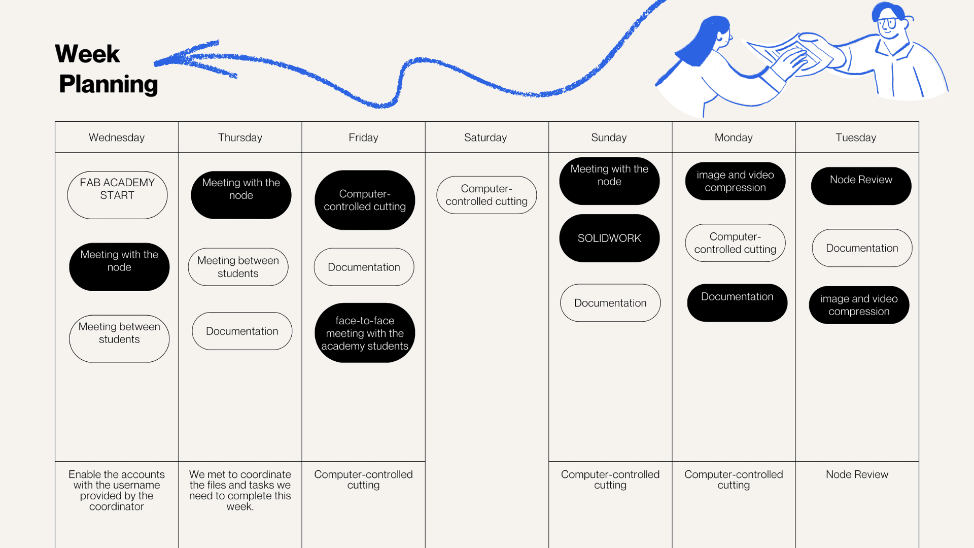
Weekly planning
During the Computer-Controlled Cutting week, group and individual activities were carried out. The group task involved laboratory safety training and characterizing the laser cutter, considering aspects such as focus, power, speed, cut type, joint clearance, and the materials it can process. All work was documented on the group website, and each participant individually wrote a reflection on the lessons learned. In the individual tasks, each participant designed, laser-cut, and documented a parametric construction kit, taking into account the characteristics of laser cutting, and also performed a cut using a vinyl cutter.
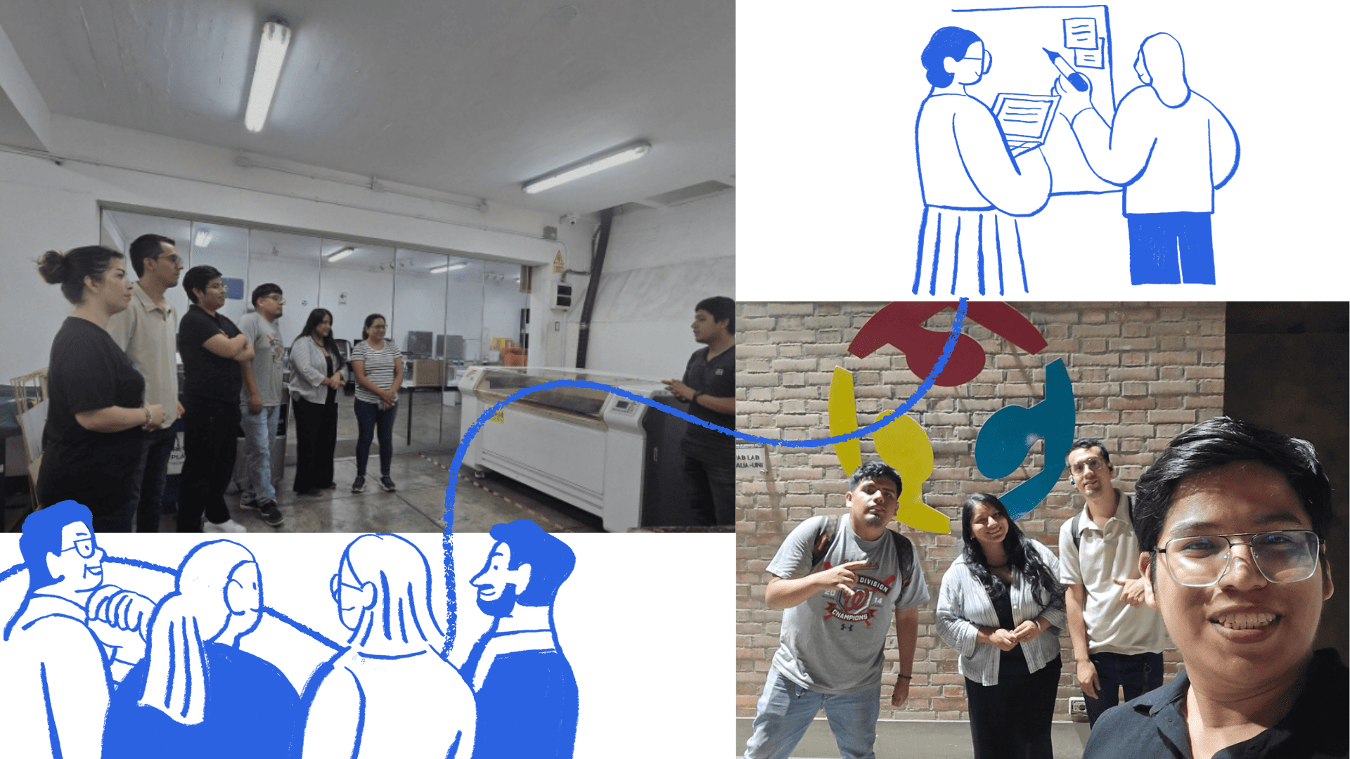
Group Work
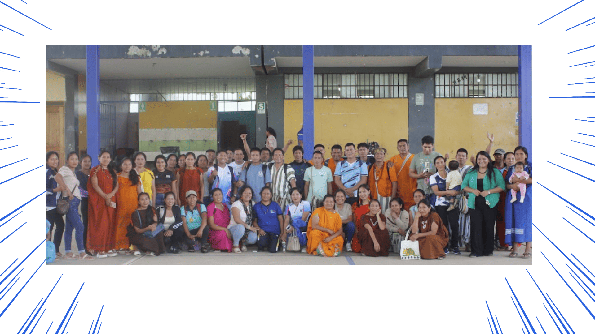
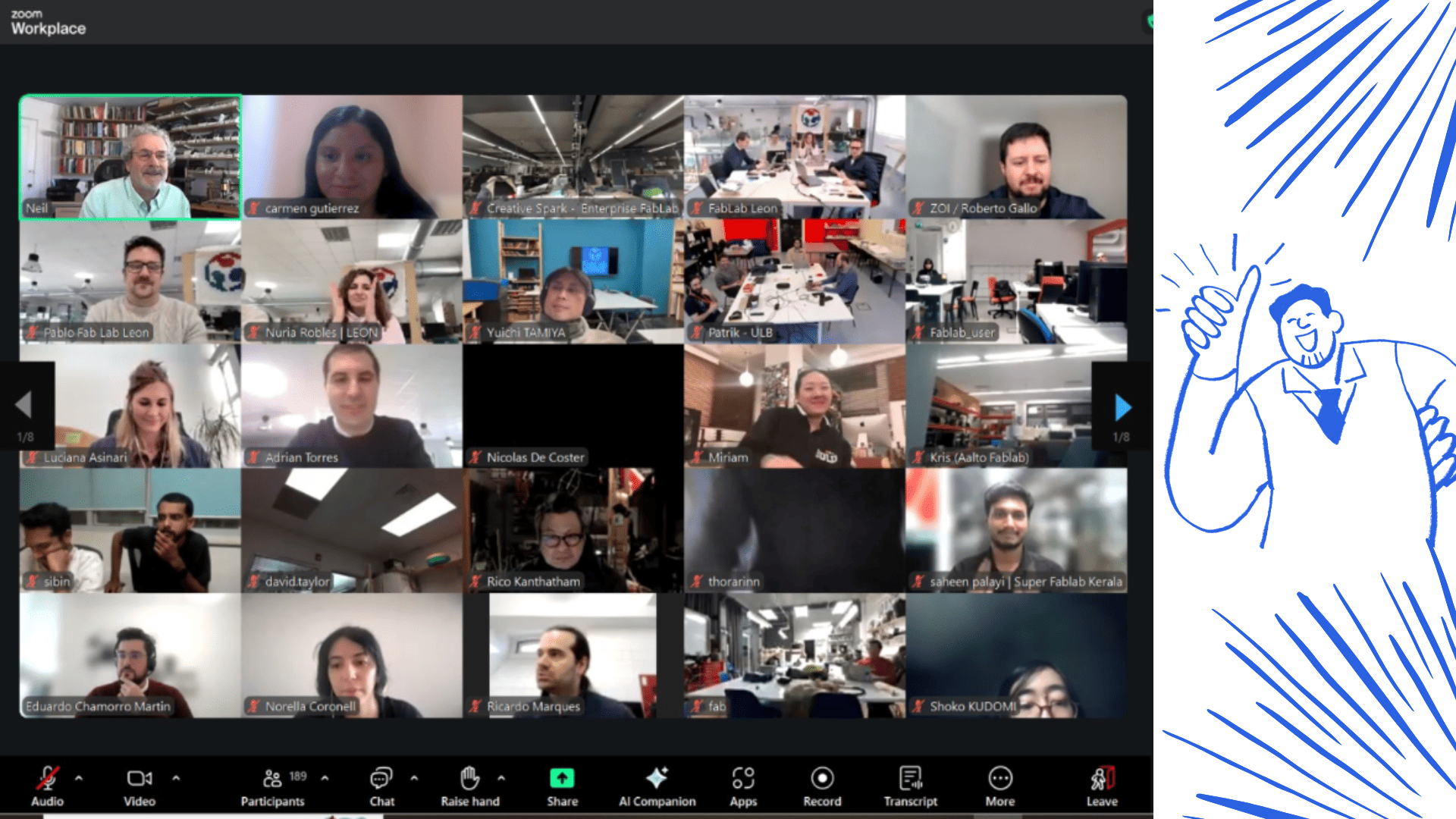
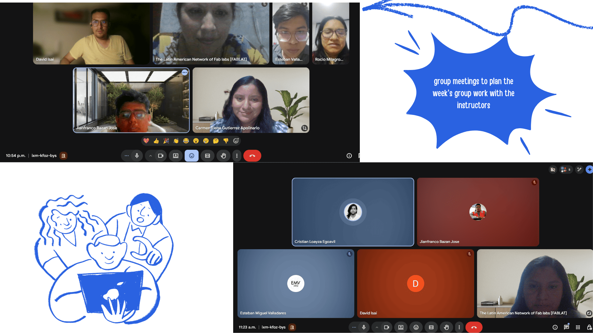
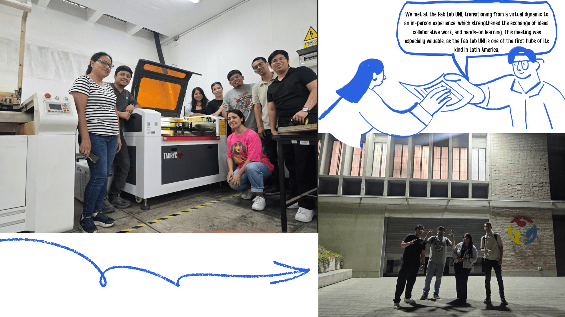
We are part of the FA network of nodes, as it was the first Fab Lab in South America. This laboratory was established between 2010 and 2011 and inaugurated during the FAB7 World Congress, an event that also marked the launch of the Fab City project. The in-person meeting allowed us to finalize our plan, explore and evaluate various materials, their applications, and the necessary files for digital fabrication. On this occasion, we were able to meet to develop the group assignment, strengthen our collaboration, get to know each other better, and share the projects that each node is currently developing. We were guided by Evelyn Cuadrado as instructor and Grace Schwan as academic support. The development of Task 3 is presented below. BLAB Peru is a node with presence in various regions of the country, including Lima, Junín, and Loreto. For this group project, we first held a virtual meeting to coordinate ideas, objectives, and tasks. Subsequently, we had the opportunity to meet in person at the FABLAB UNI laboratory, a key space within the network. For more information about our group work, visit: Group Project Page
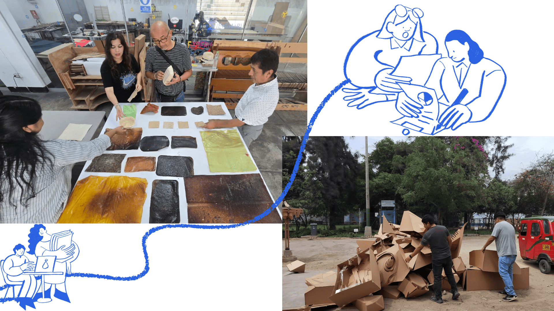
collection of materials
Regarding materials, a group call discussed the different types of materials available at each node, highlighting the importance of collecting and using recycled materials for project development. Special emphasis was placed on utilizing reusable resources as part of a sustainable practice within the Fab Lab network. The materials used at the Satipo node were also reviewed, where biomaterials such as bio-paper and bio-polymers are being developed and are currently being experimented with and applied in various projects. These materials were presented and shared with the group as a reference for future fabrication proposals. During the visit to the UNI Fab Lab, we also had the opportunity to present our ongoing projects and received guidance from the lab director, with whom we shared our progress and approaches. Furthermore, being located within the Faculty of Architecture, the lab allowed us to identify and recycle readily available materials such as cardboard, acrylic, and MDF, which were reused for prototype development and digital fabrication exercises.
Individual tasks
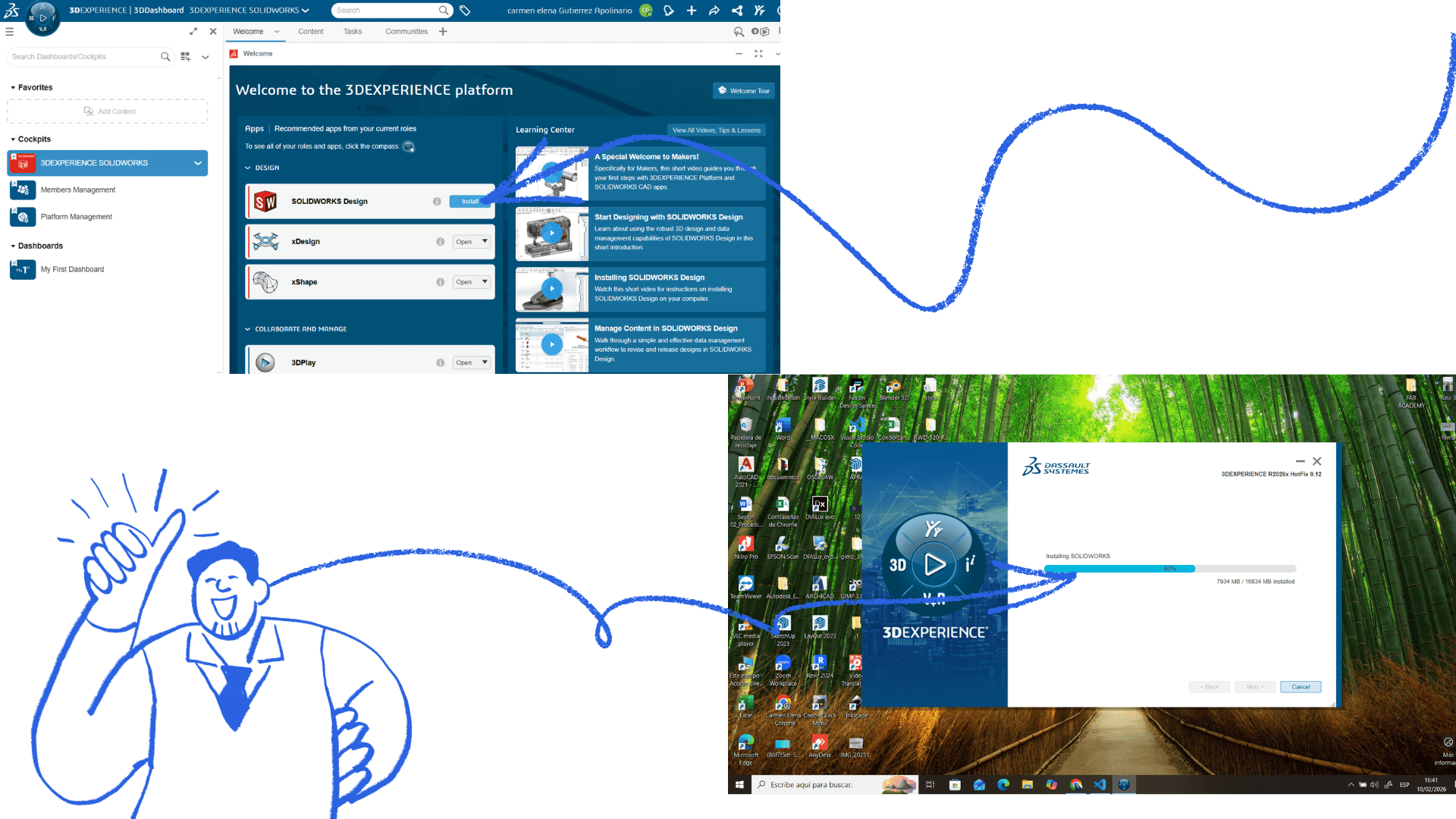
Parametric construction kit
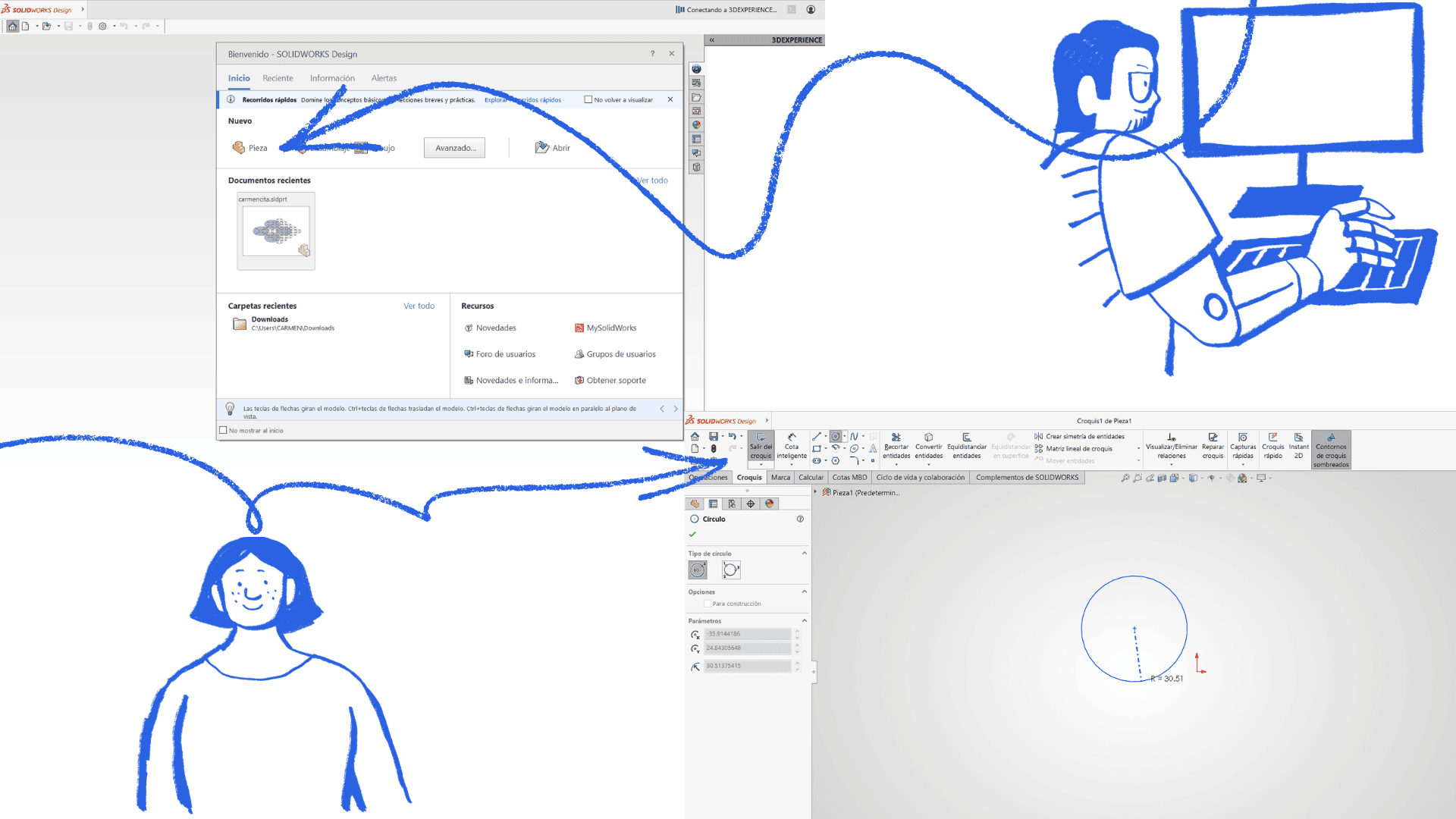
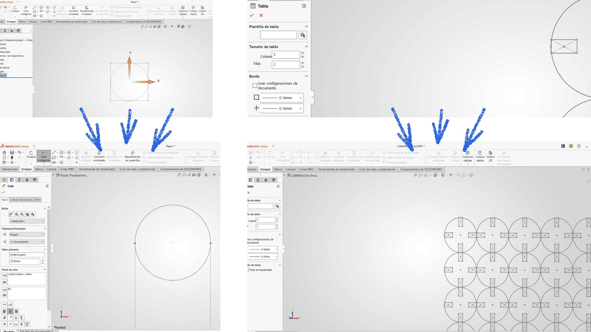
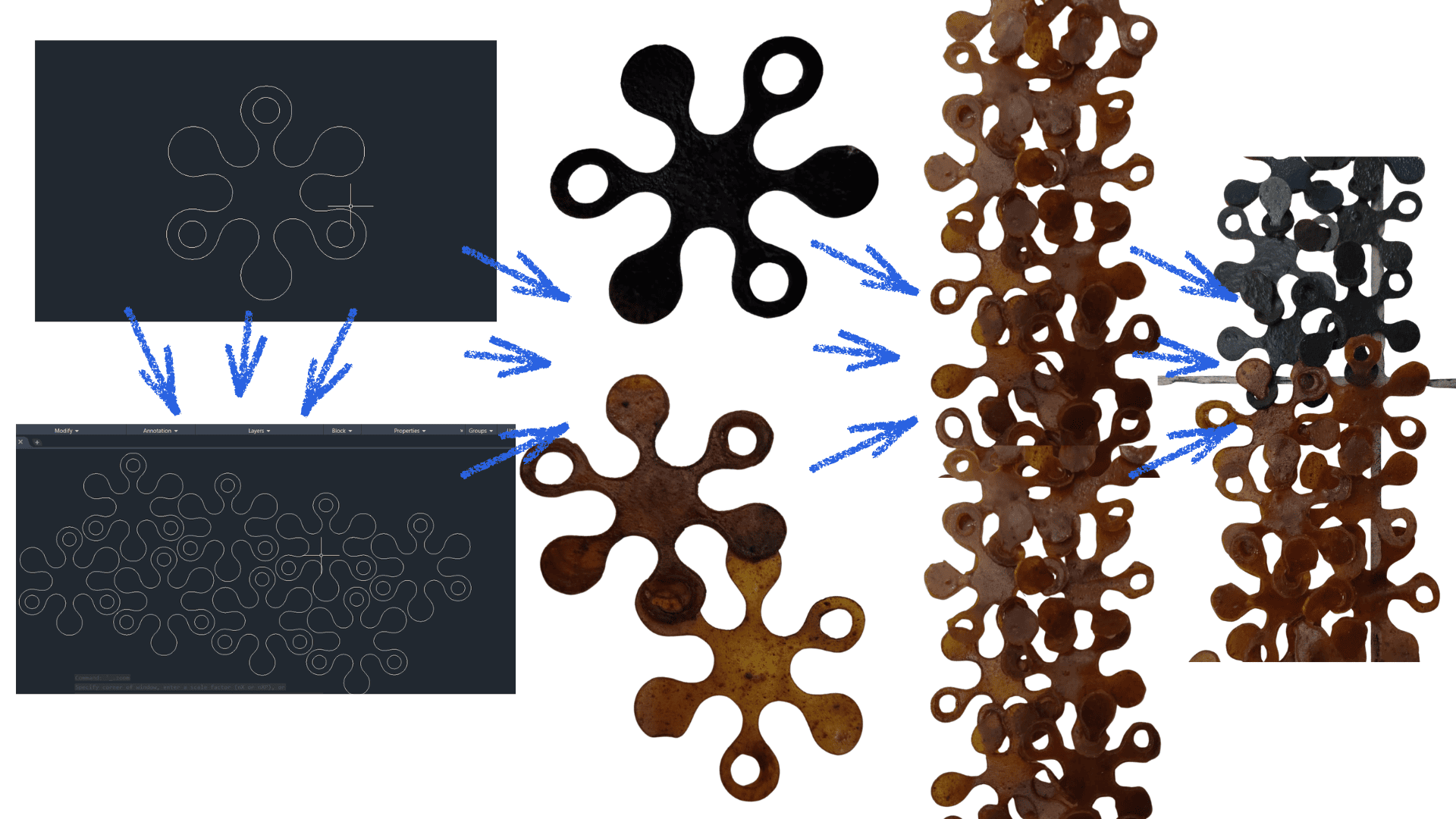
I downloaded and installed the SolidWorks software and then began the design process, starting with a basic shape—in this case, a circle. The intention was to experiment with the geometry and play with the form, establishing specific parameters and measurements from the outset. To do this, I took into account the actual thickness of the materials to be used: 2 mm MDF and 2.01 mm biopolymer. It was necessary to apply constraints and geometric relationships to ensure that the object had the correct proportions and maintained dimensional consistency. I also used the equations and values option in the toolbar to add the kerf to the joints in the base module. Subsequently, I performed the dimensioning, considering this reference, subtracting the kerf measurement from the joints to guarantee a proper fit between the pieces. Once the parameterization process was complete, I configured an array pattern to generate multiple copies along the X and Y axes. Finally, the file was exported in a format compatible with laser cutting and processed in RDWorks for manufacturing.
 >
>
creations with the parametric kit
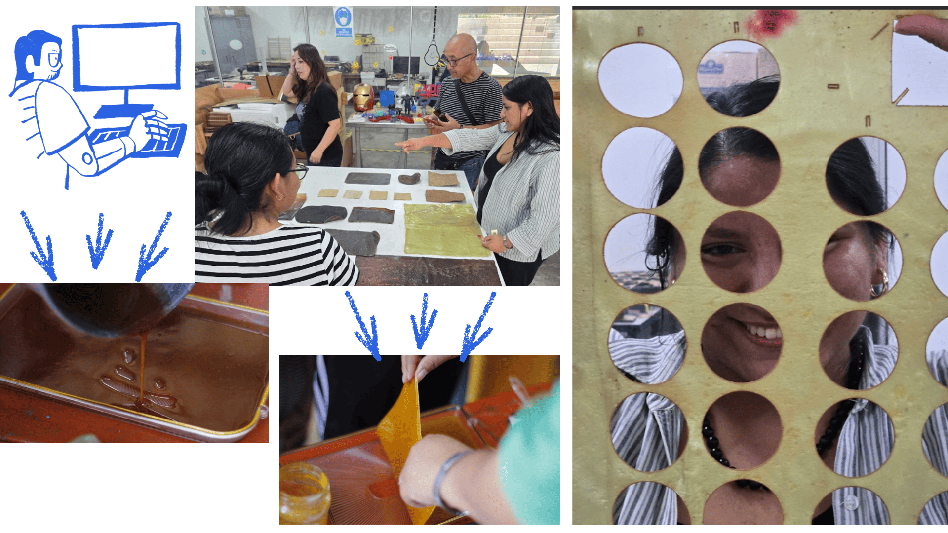
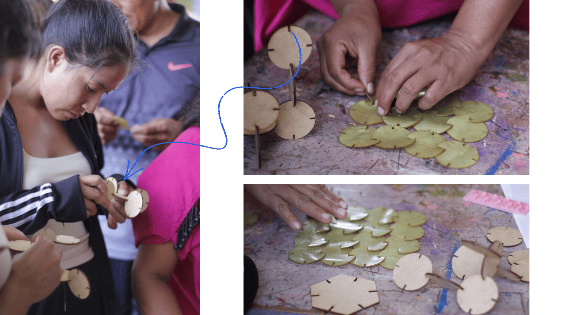
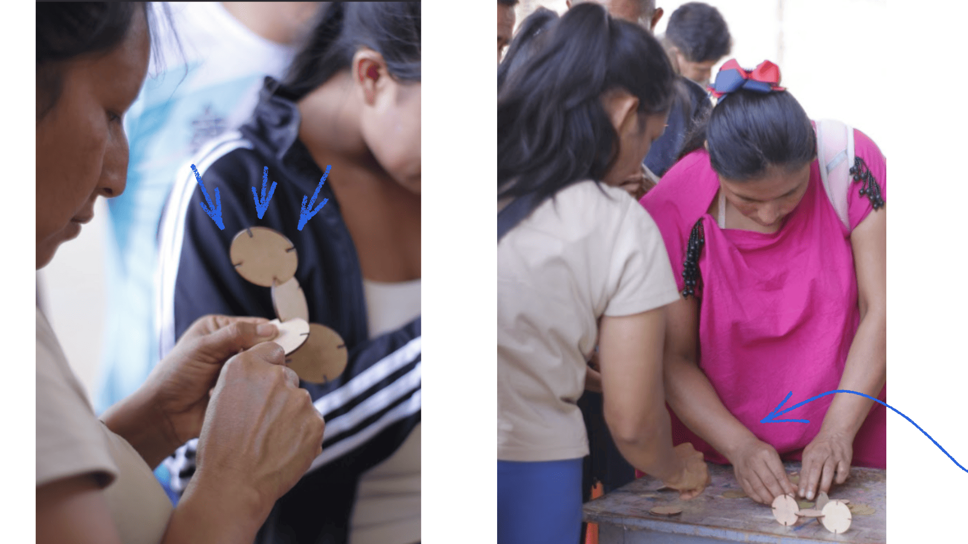
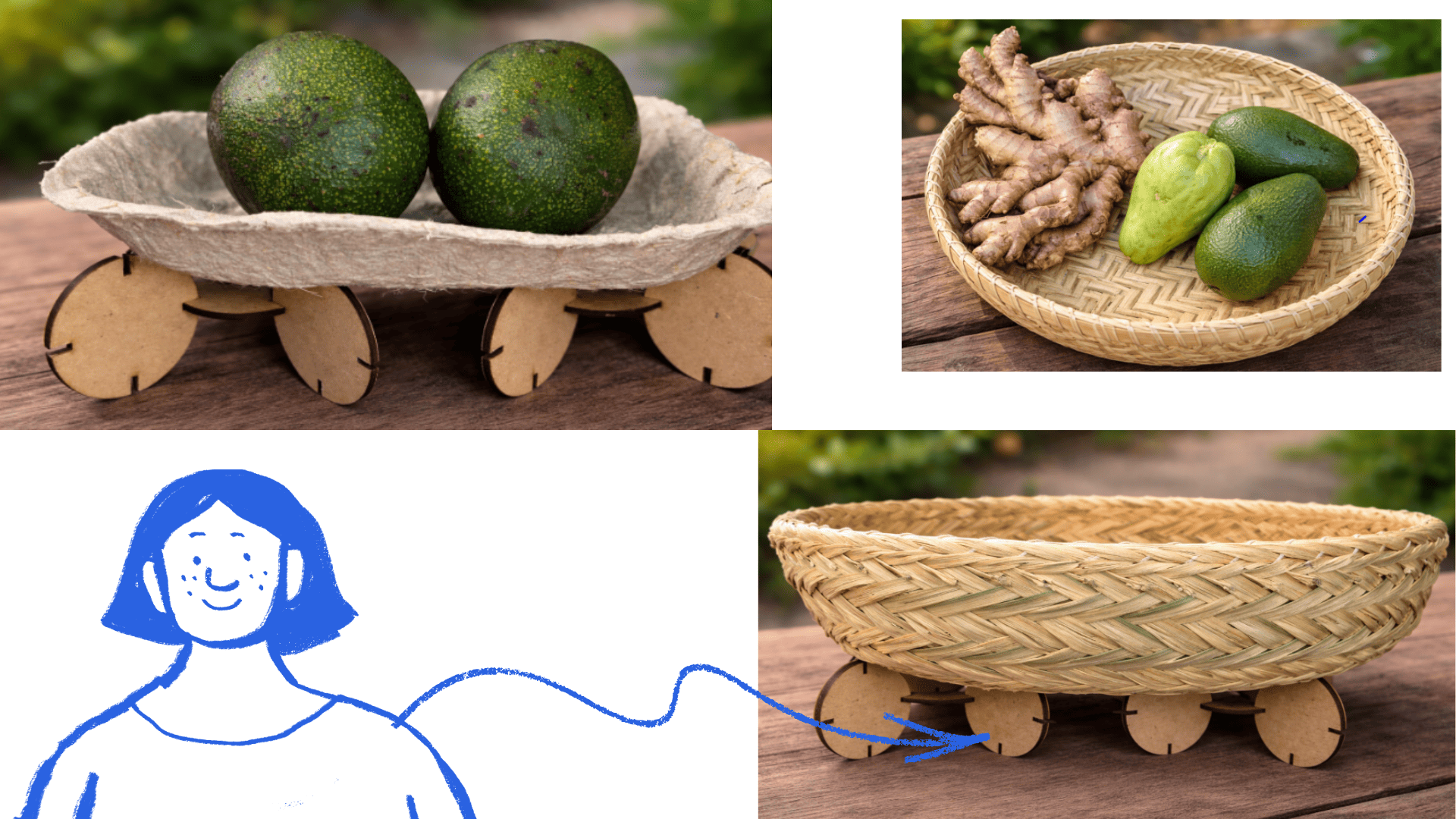
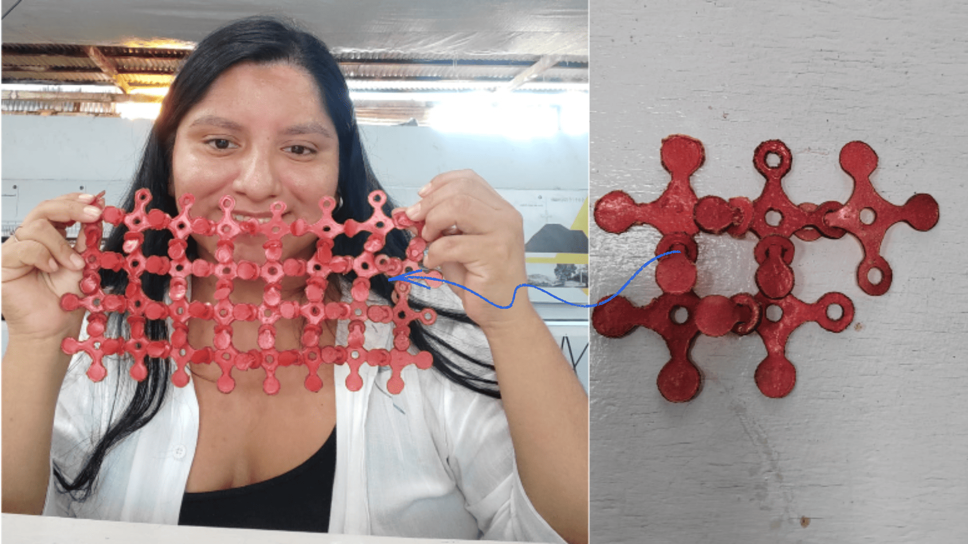
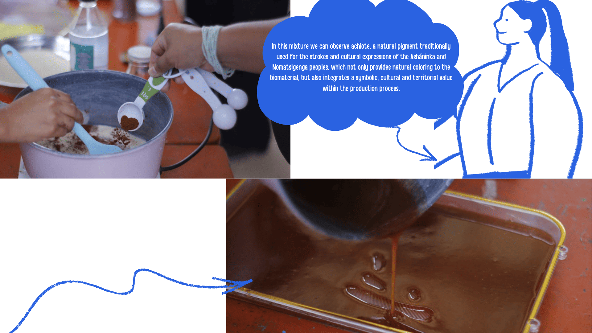
In this project, I had the opportunity to explore various materials: one commercial, like MDF, and another developed in the biomaterials workshops, specifically a biopolymer. In the creation of these biomaterials, we incorporated natural pigments from local communities, such as annatto, turmeric, and coffee grounds. This allowed us not only to experiment with physical properties but also to integrate local identity and knowledge into the process. This week, we conducted a workshop for teachers from Pangoa and Satipo, in the native community of Cheni. This experience was very meaningful, as the training was geared toward participants from across the Pangoa River basin. In this workshop, I shared the work developed in week 3, especially the biomaterial creation process and the parametric cuts made with the biopolymer. The teachers quickly associated the parametric pieces with pedagogical applications. They proposed using them as a teaching resource for addition and subtraction, by adding or removing circles that fit together without adhesives, thanks to the interlocking system. The same thing happened with the pieces made of MDF. It was very interesting to observe how they began to generate different shapes and configurations from the same basic module. The most valuable aspect was understanding, from a different perspective, the potential of these designs. In addition to their educational use, they identified that they could function as supports for baskets made in the community, creating bases for plates or display structures. This experience demonstrated how parametric design and biomaterials can interact with pedagogy and local production, expanding their application possibilities.
creations with the parametric kit
creations with the parametric kit
creations with the parametric kit
creations with the parametric kit
creations with the parametric kit
creations with the parametric kit
creations with the parametric kit
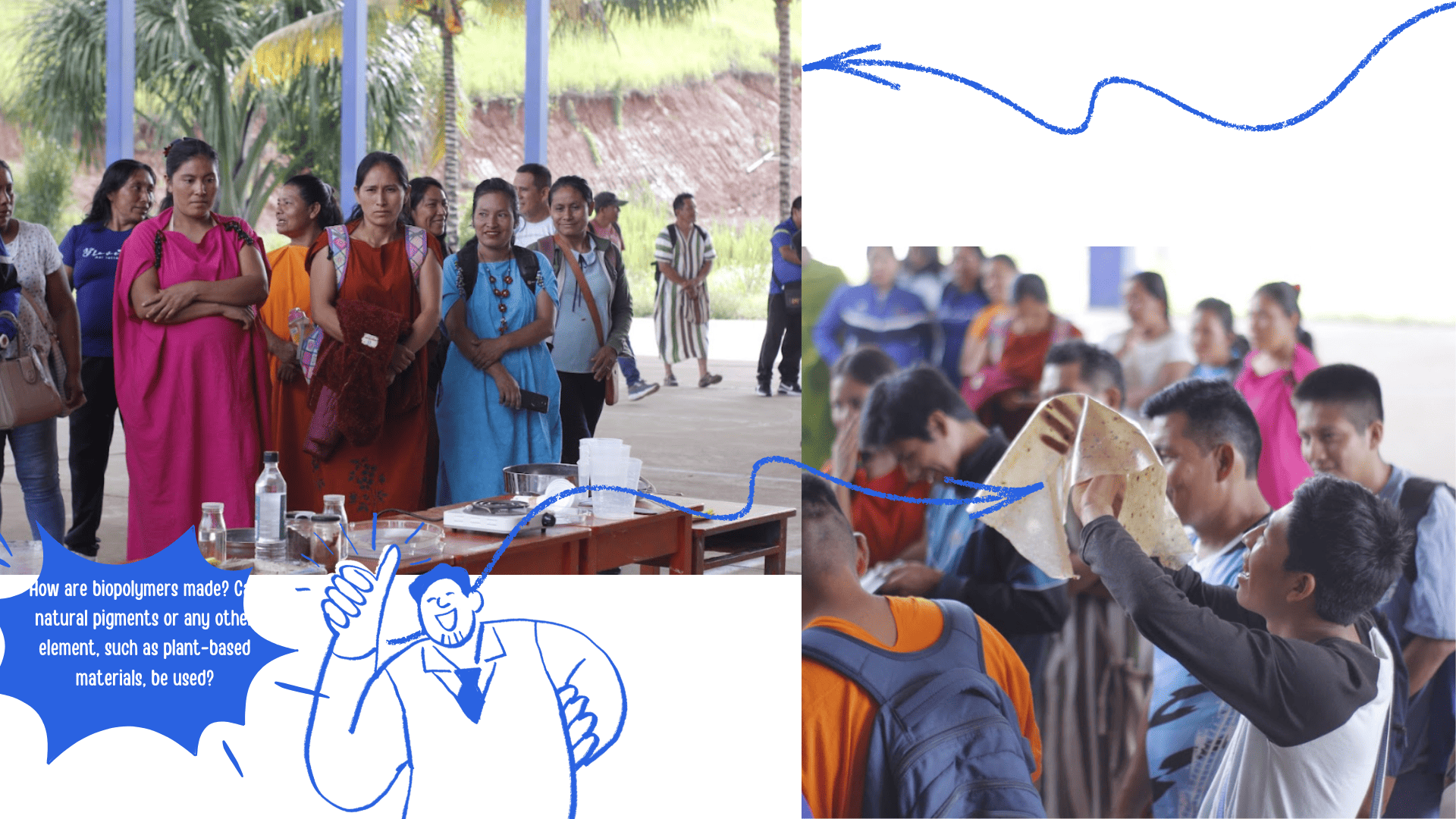
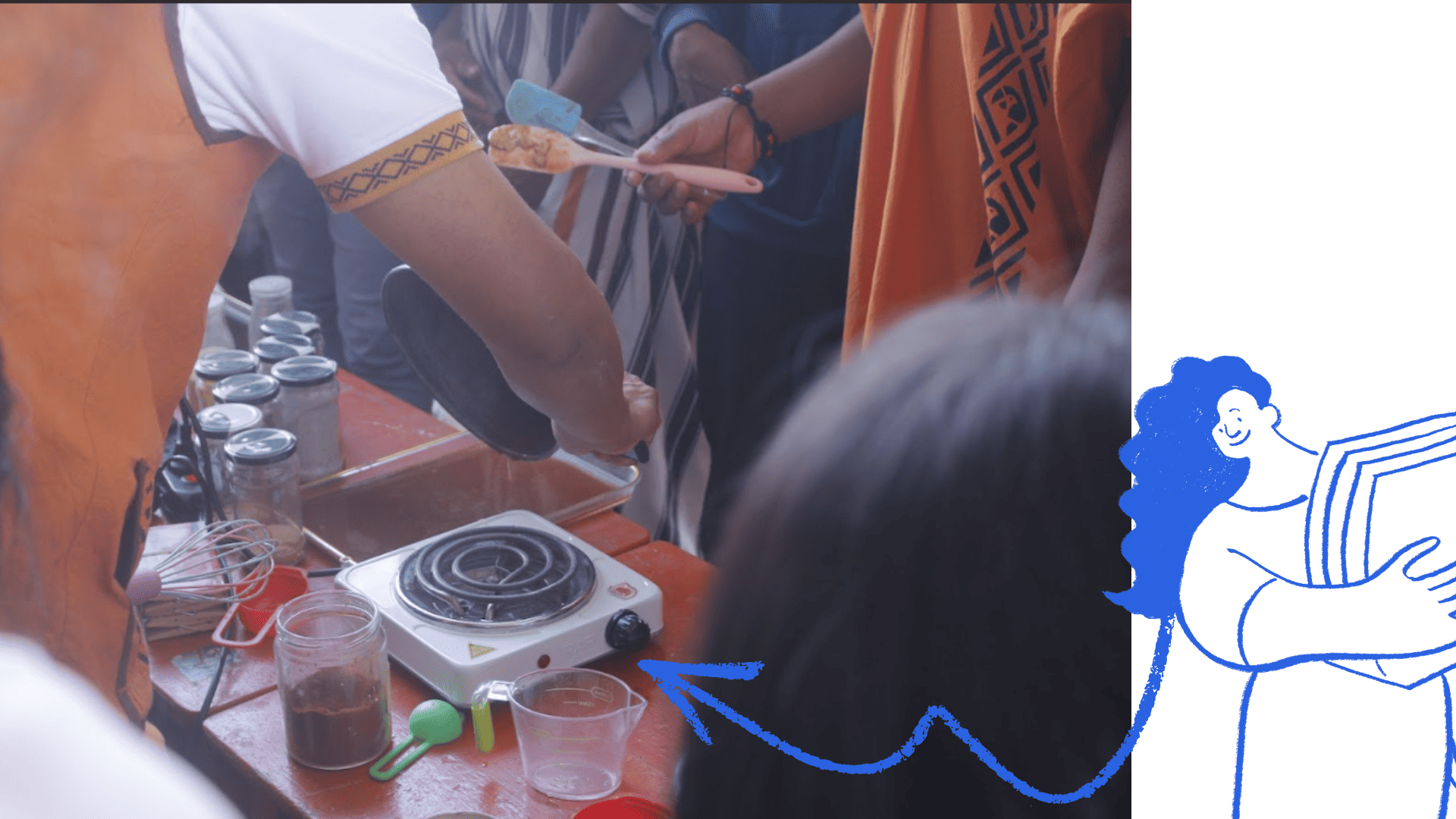
Let's see how we can create biopolymers and what we can use from our living laboratory, the forest.
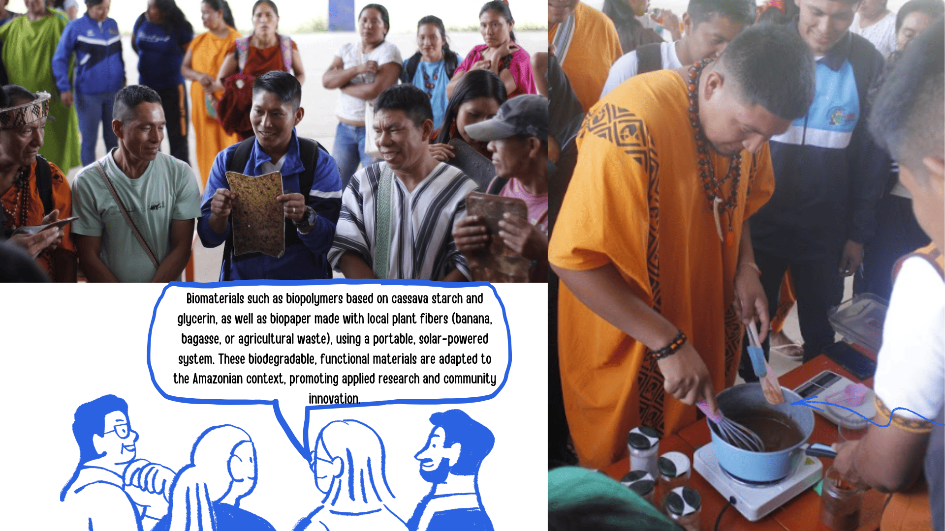
Biomaterials such as biopolymers based on cassava starch and glycerin, as well as biopaper made with local plant fibers (banana, bagasse, or agricultural waste), using a portable, solar-powered system. These biodegradable, functional materials are adapted to the Amazonian context, promoting applied research and community innovation.
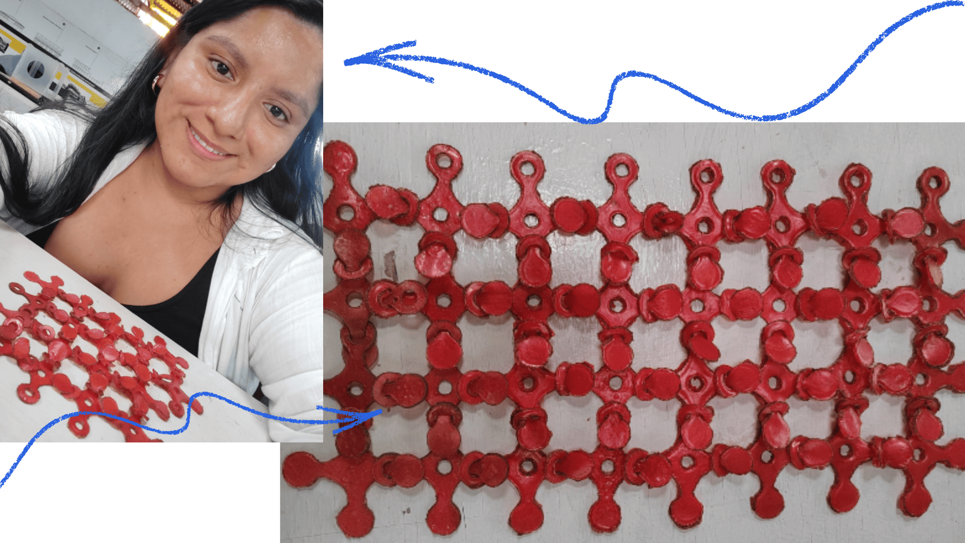
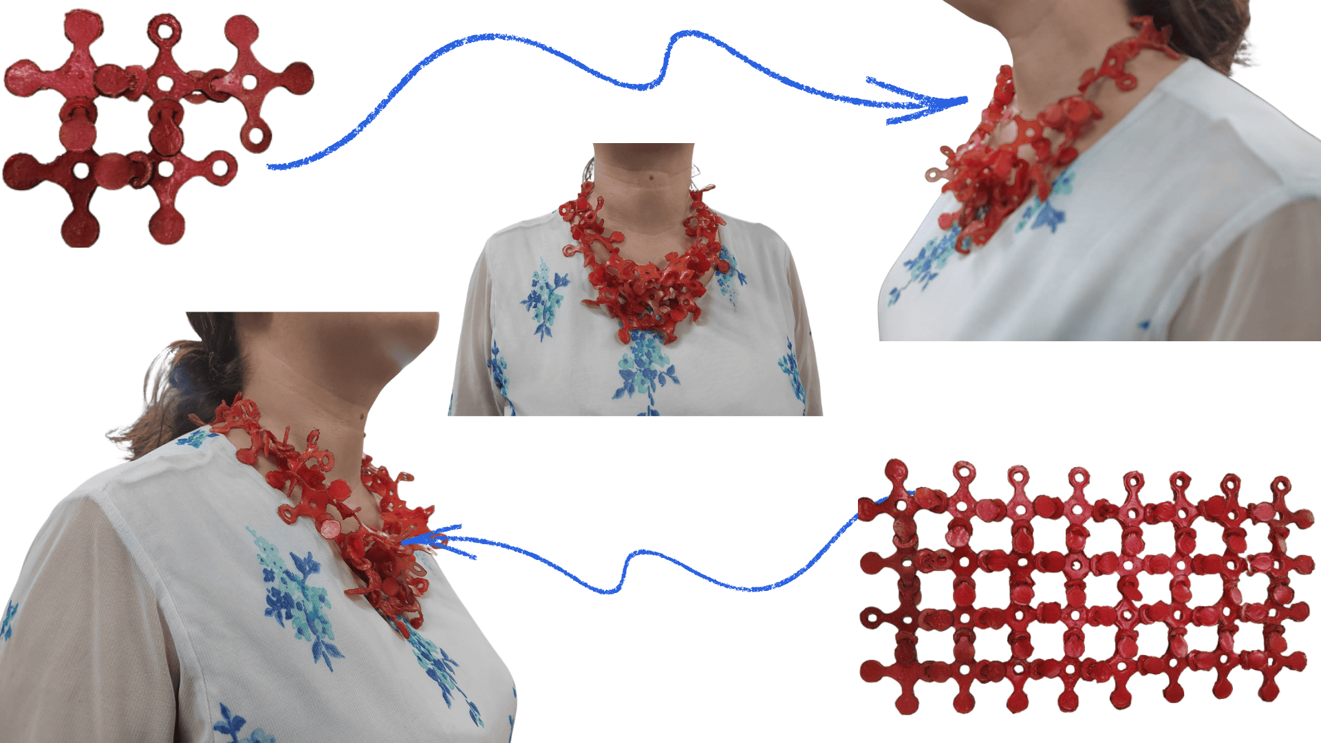
We use biomaterials made with local ingredients and natural pigments like annatto to bring cultural identity to the design. Through a parametric kit, we generate modular forms that are then laser-cut, integrating traditional knowledge and digital fabrication.
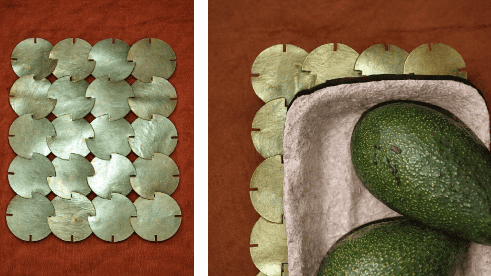
Finally, we built an assembly system in which the pieces fit together without glue, allowing for strong, detachable, and reusable joints. This parametric kit not only facilitates formal experimentation but also opens up possibilities for its application in the creation of sustainable crafts, integrating traditional knowledge, technological innovation, and digital fabrication.
Biomaterials such as biopolymers based on cassava starch and glycerin, as well as biopaper made with local plant fibers (banana, bagasse, or agricultural waste), using a portable, solar-powered system. These biodegradable, functional materials are adapted to the Amazonian context, promoting applied research and community innovation.
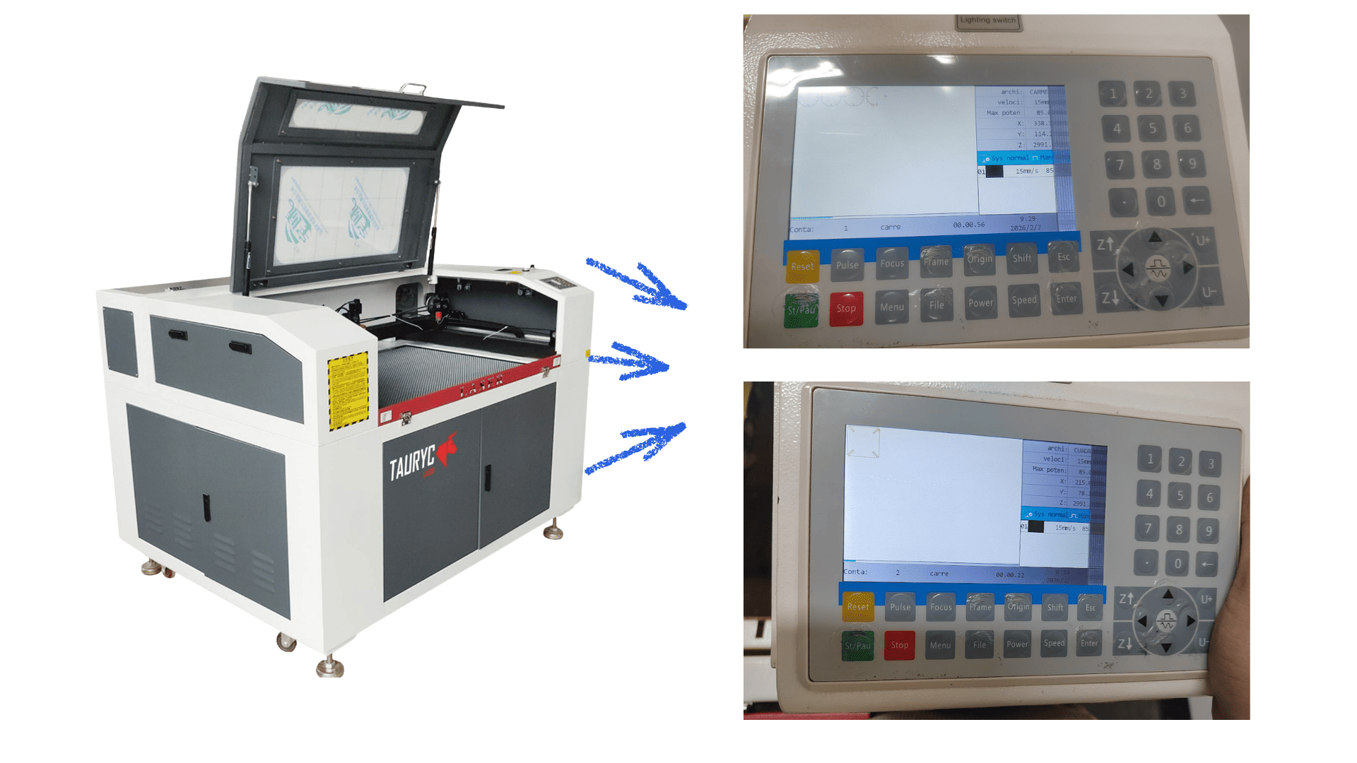
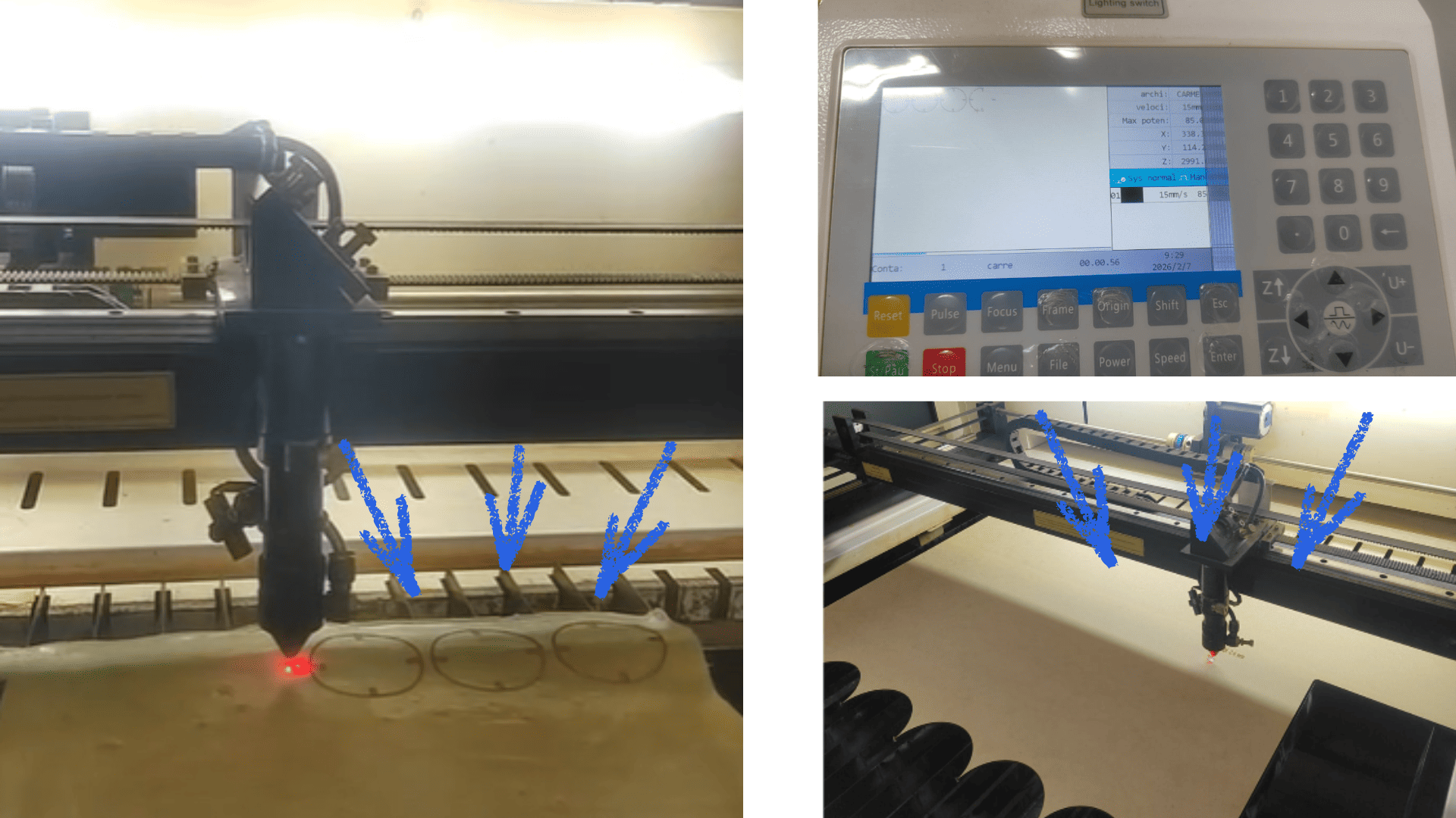
For laser cutting, parameters such as a cutting speed of 15 mm/s and 85% power were configured. These settings optimized cut quality, preventing excessive burning and ensuring the correct definition of the generated parametric patterns. The combination of these parameters facilitates the production of modular parts that can be assembled and adapted to different configurations, such as fashion accessories.
The project incorporates parametric design and the use of coffee-based composite biomaterials and joining elements such as wooden sticks. This allows for the creation of modular pieces that can be easily assembled, offering flexibility in the final configuration and promoting the use of sustainable materials.
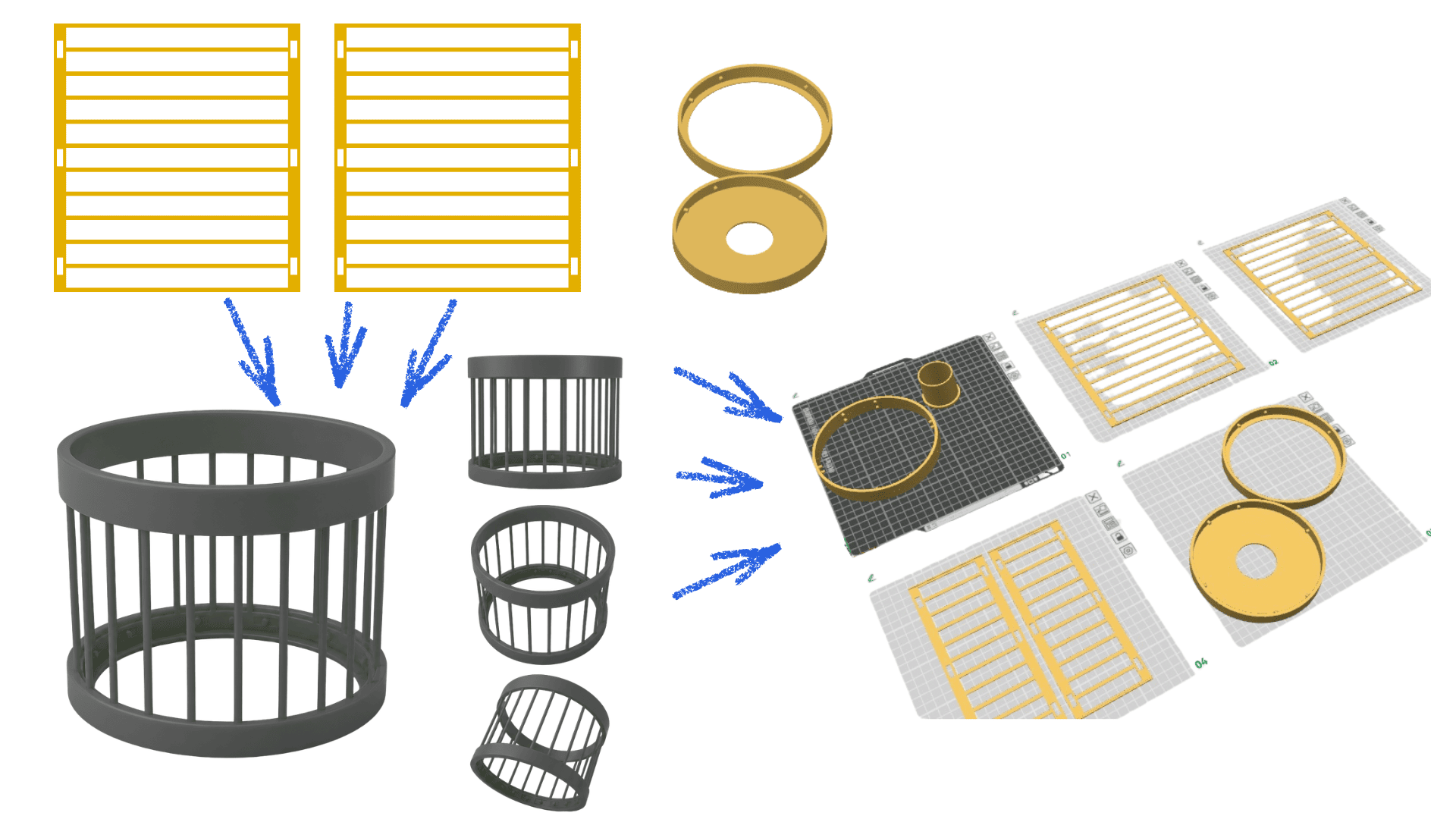
The project also incorporates a 3D-printed base, which serves as a structural support for a lamp made from the coffee-based biomaterial. This combination of digital fabrication and sustainable materials allows for the exploration of applications in different contexts, such as lighting, fashion, and accessory design, demonstrating the adaptability of the parametric system.
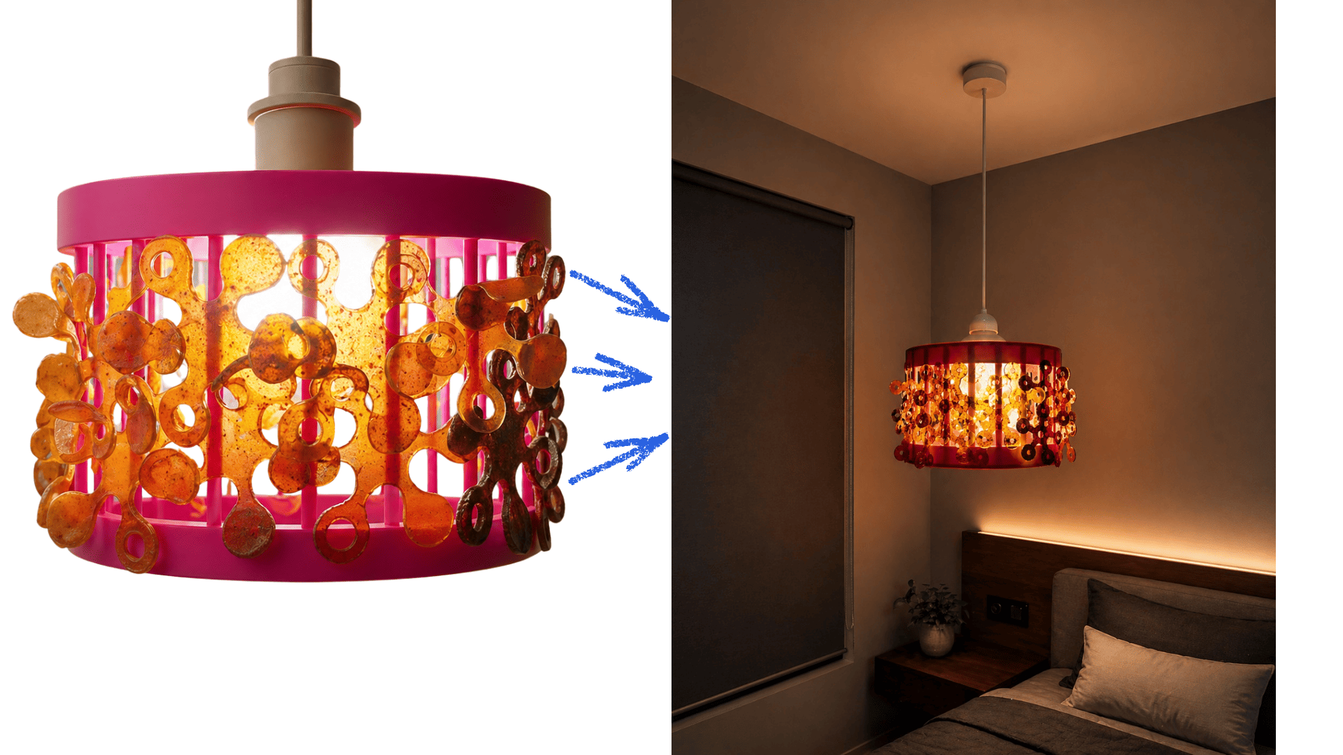
In this way, I was able to assemble a lamp by combining a 3D-printed base with a biomaterial made from coffee and reinforced with wooden sticks. This integration resulted in a functional, sustainable structure adaptable to different design applications.
AI Prompt – Sustainable Lamp
“Sustainable lamp made with coffee-based biomaterial and a structure assembled with wooden sticks, with a 3D-printed base. Organic parametric design, natural texture, brown and beige tones. The lamp is lit in a modern and cozy room, softly illuminating the space. Warm ambiance, minimalist style, placed on a table or shelf. The detail of the recycled material and its modular structure are appreciated. Soft lighting, warm shadows, realistic rendering, high quality.”
Vinyl cutting
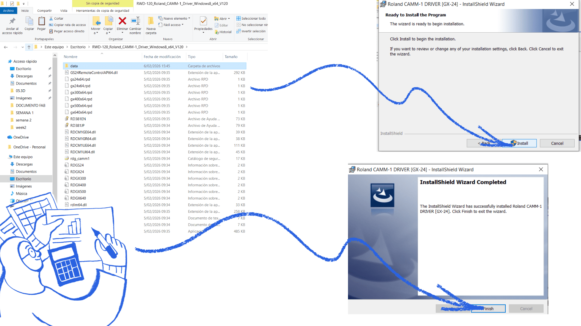
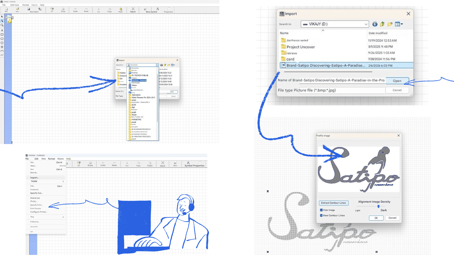
We performed the vinyl cutting using the Roland GX-24 machine at Fab Lab UNI, which accepts materials up to 60 cm wide. Initially, we installed the corresponding software. The lab manager explained how the machine works, its main parameters, and provided recommendations for proper use.
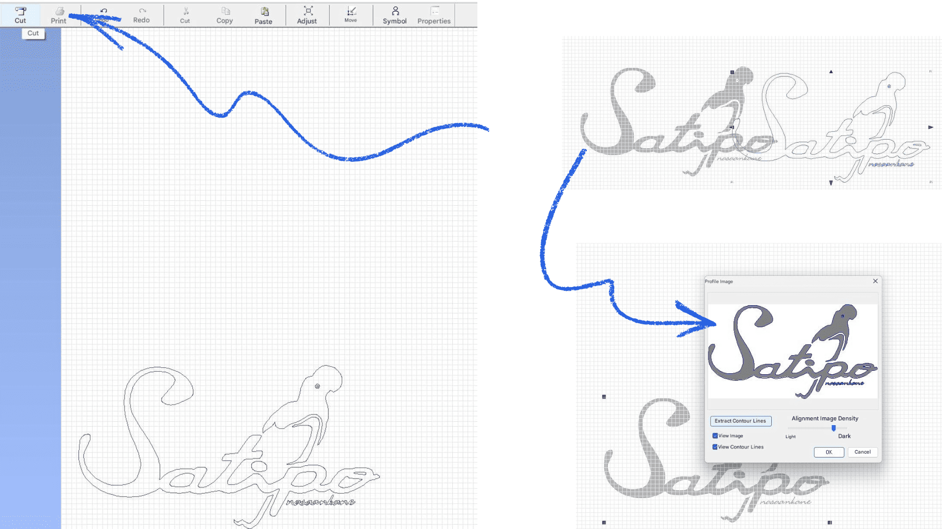
Afterward, we began working with the vinyl cutter. We used a JPG image, which was imported into the program. Using the same software, we performed the vectorization process (rasterization/tracing), which converts the image into cutting lines so it can be sent correctly to the machine. Then, we adjusted the cutting parameters, such as speed and pressure, according to the type of vinyl used.
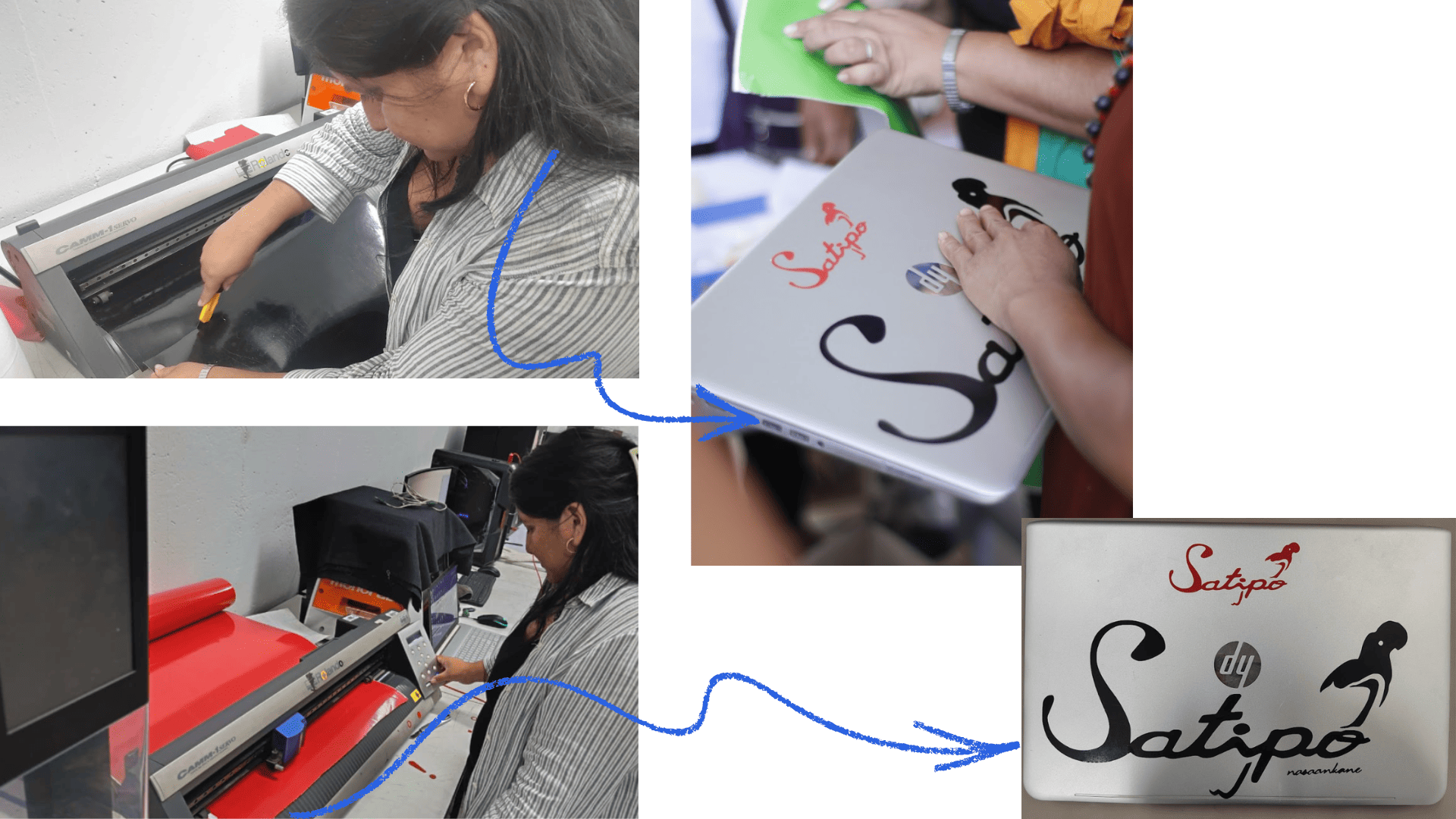
I decided to work with the Satipo brand logo, conducting tests in different sizes and colors. Once the cut was made, I proceeded with the weeding and transfer process to apply it to my laptop. The result was satisfactory, as the vinyl adhered correctly, without tearing or causing any difficulties during application.
This practice allowed for a better understanding of the workflow from file preparation to final vinyl application, as well as the importance of properly configuring the parameters according to the material.
Vinyl cutting
Vinyl cutting
creations with vinyl
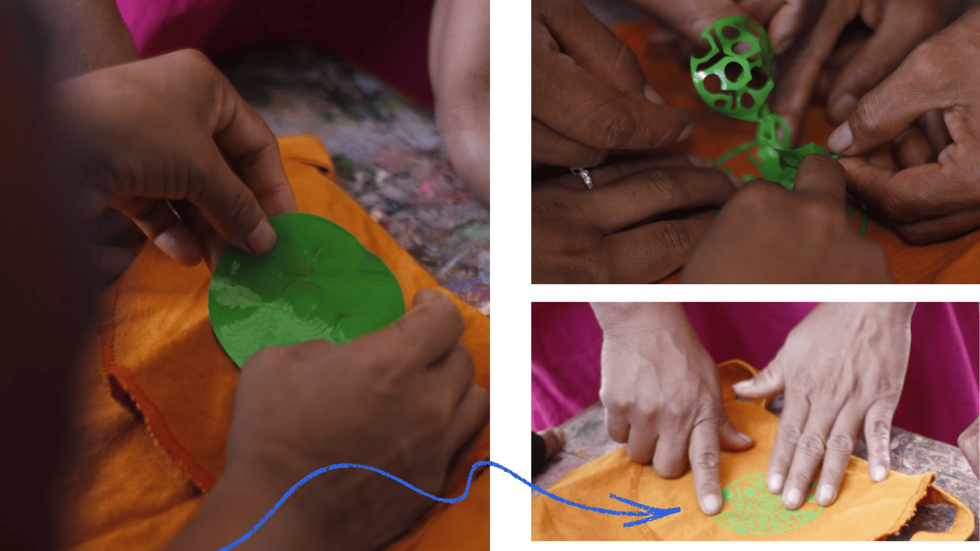
During the activity in the native community of Cheni, I also had the opportunity to share my knowledge of vinyl cutting with the participating teachers. I brought some pre-cut versions of the REGEN logo to demonstrate the process and the application possibilities of this technique.
The teachers applied the vinyl to a bag made of tocuyo, a traditional fabric, dyed with pochotoroki, a natural bark used to dye cusma (a type of tunic). The experience was very enriching, as it allowed us to integrate digital technology with the community's own knowledge and materials.
In this way, it became clear how vinyl cutting can complement artisanal processes, generating new design proposals that respect local cultural identity.
Vinyl cutting
Vinyl cutting
Reflection
2D and 3D design programs play a fundamental role in current creative and technical processes. 2D programs allow you to work on flat surfaces, facilitating the creation of drawings, plans, illustrations, and graphic designs. Their simplicity makes them ideal for initial conceptualization, rapid visual communication, and the development of basic ideas. On the other hand, 3D programs expand these possibilities by allowing you to represent objects with volume, depth, and realism. Thanks to them, it is possible to visualize spaces, products, or structures from different angles, simulate materials, and better understand the spatial relationship of elements. This is especially useful in areas such as architecture, industrial design, and animation. These two types of programs are not mutually exclusive; rather, they complement each other. 2D design is usually the starting point for sketches and diagrams, while 3D design allows you to transform those ideas into more complete and realistic models. Together, the appropriate use of 2D and 3D tools strengthens creativity, improves design accuracy, and optimizes learning and production processes.