IM 70.3 Training: see about page to understand this.
On holidays from 1st to 17th May.
FABACADEMY
Recitation
FabLab
Global Open Time
Assignment
Training
Work
In the mobile version, you have to tap each day to display the data.
Starting Point
After several weeks developing different parts of PinSocc Ball, this week allows me to start bringing the whole project together as a single integrated system.
Until now, I had been working on many elements separately — electronics, mechanics, interaction, and programming — but the goal now is to understand how they all coexist within the final game experience.
This is the moment when the project starts to feel less like a collection of tests and more like a complete product.
Individual assignment
Design and document the system integration for your final project.
From the beginning, I want PinSocc Ball to feel more like a real game experience than just an electronic project. The idea combines the fast and visual dynamics of a pinball machine with a physical interaction inspired by arcade games, where the player is constantly involved and the system responds in real time throughout the match.
The experience is designed to be simple and intuitive from the very first moment. The player powers on the system, starts the match, and begins interacting with the hand-shaped flippers to keep the ball in play and try to score goals before the time runs out.
Meanwhile, the scoreboard, visual effects, and timer are continuously updated, making the whole system feel alive and reactive.
Every time a goal is detected, the project responds immediately with LED effects, animations, and a score update, reinforcing the feeling of a dynamic and active game.
Although internally the system uses a distributed architecture based on ESP32 boards, IR sensors, servos, and wireless communication through ESP-NOW, my goal is that, from the user’s point of view, everything works as a single integrated and fluid system.
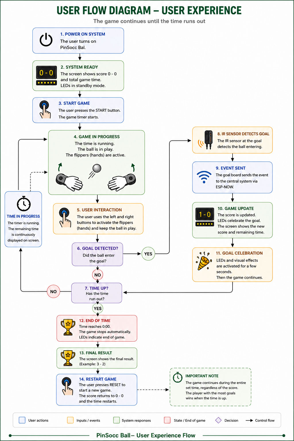
The following diagram represents this user experience flow, showing how the player interacts with PinSocc Ball and how the system responds during the different stages of the match.
User Experience Flow Diagram
I decided to represent it as an image (generated by AI)
User Experience Flow Diagram -AI Generated with the text below- (size: 0 Kb -click to enlarge-).
User Experience text Flow
PinSocc Ball is an interactive game inspired by pinball mechanics, where the match takes place during a fixed amount of time.
When the system is powered on, the main display shows the initial score and the total game time. Once the user presses the START button, the countdown begins and the game enters its active state.
During gameplay:
the hand-shaped flippers remain active,
players interact using physical buttons,
the remaining time is continuously updated on the display,
and the IR sensors monitor when the ball enters the goal areas.
When a goal is detected:
the IR sensor detects the ball entering the goal,
the event is transmitted to the central system using ESP-NOW,
the score is updated,
and visual LED effects are activated.
After the goal celebration animation, the game automatically continues as long as there is remaining time available.
The match does not end when a specific score is reached. The game continues until the timer reaches zero.
Once the time is over:
the system stops the game,
disables the flippers,
shows the final result,
and allows the user to start a new match using the RESET button.
Project system diagram
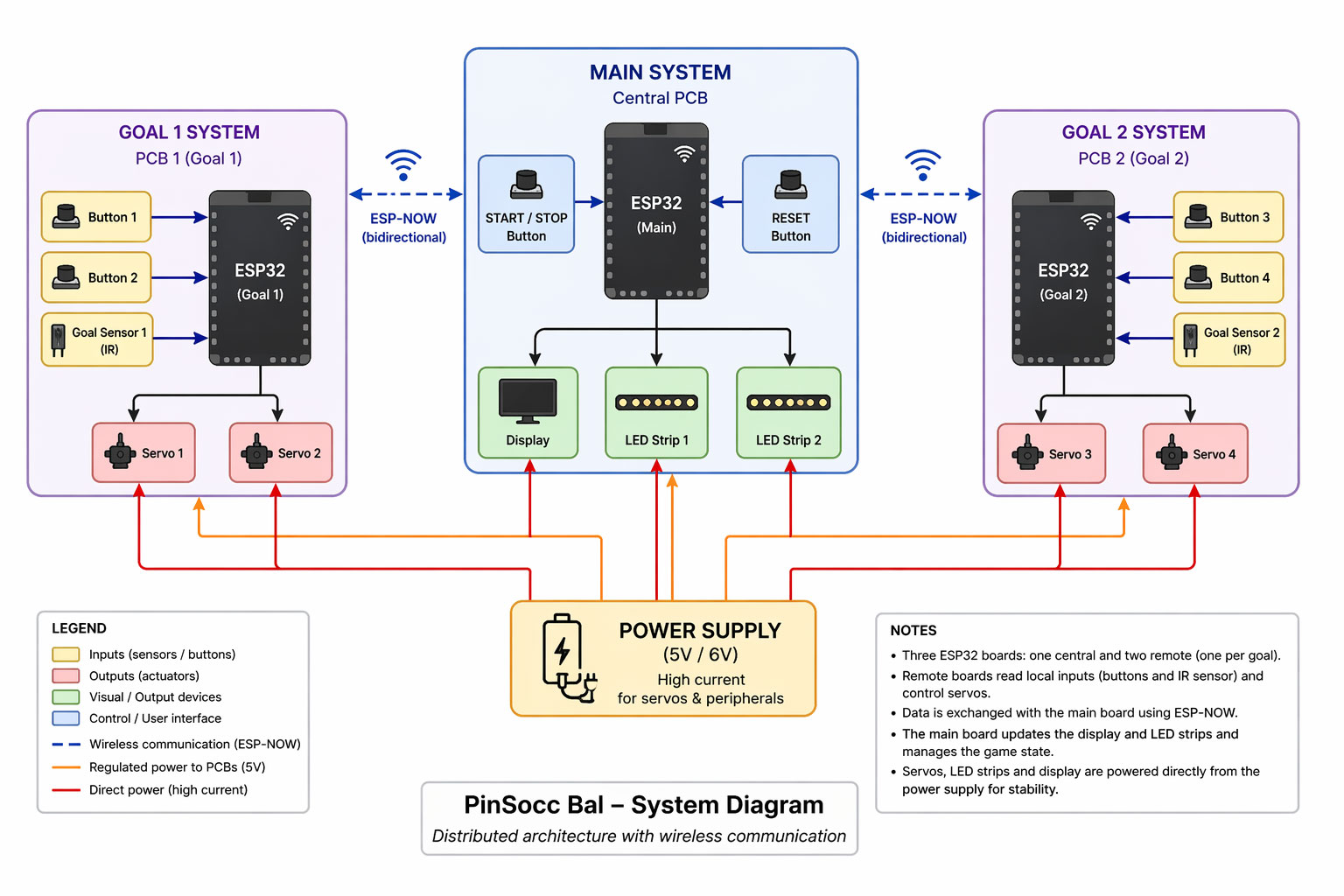
One of the most important parts of developing PinSocc Ball is integrating all the electronic and mechanical systems that allow the project to work as a single interactive experience.
Although from the outside the game feels simple and fluid, internally it is based on a distributed architecture where different boards, sensors, actuators, and visual output devices work together in real time.
To organize this communication, the project is divided into several subsystems connected through ESP-NOW. Each goal has its own ESP32 board, which reads the local buttons and IR sensor, while also controlling the servos that move the hand-shaped flippers.
At the same time, the central system manages the overall game state, updates the score, controls the LED lighting, and keeps the whole experience synchronized during the match.
The following diagram shows the general architecture of the project, including how the electronic modules, power distribution, and wireless communication are integrated inside PinSocc Ball.
User Experience Flow Diagram -AI Generated- (size: 0 Kb -click to enlarge-).
ChatGPT user Experience Flow Diagram PromptShow prompt
English
Create a clean modern vector technical infographic showing the electronic architecture of a system called “PinSocc Bal – System Diagram”. Use a light gray background, minimalist engineering style, soft pastel colors, clean lines, subtle shadows, and flat vector icons. Horizontal layout with three main sections aligned left to right: “GOAL 1 SYSTEM”, “MAIN SYSTEM”, and “GOAL 2 SYSTEM”.
Overall layout
* Each subsystem inside a rounded rectangle with soft blue/purple borders.
* Use modern sans-serif typography.
* Professional IoT / embedded systems engineering diagram style.
Left block – GOAL 1 SYSTEM
Title:
* “GOAL 1 SYSTEM”
* subtitle “PCB 1 (Goal 1)”
Contents:
* Centered black ESP32 board labeled “ESP32 (Goal 1)”.
* On the left side:
* Button 1
* Button 2
* Goal Sensor 1 (IR)
* Blue arrows pointing into the ESP32.
* Below the ESP32:
* Servo 1
* Servo 2
* Black arrows from ESP32 to servos.
Center block – MAIN SYSTEM
Title:
* “MAIN SYSTEM”
* subtitle “Central PCB”
Contents:
* Black ESP32 board in the center labeled “ESP32 (Main)”.
* Left side:
* START / STOP Button
* Right side:
* RESET Button
* Below:
* Display
* LED Strip 1
* LED Strip 2
* Black arrows from ESP32 to output devices.
* Wireless ESP-NOW communication with Goal 1 and Goal 2 using dashed blue bidirectional lines and WiFi symbols.
Right block – GOAL 2 SYSTEM
Title:
* “GOAL 2 SYSTEM”
* subtitle “PCB 2 (Goal 2)”
Contents:
* Centered black ESP32 board labeled “ESP32 (Goal 2)”.
* On the right side:
* Button 3
* Button 4
* Goal Sensor 2 (IR)
* Blue arrows toward the ESP32.
* Below:
* Servo 3
* Servo 4
* Black arrows from ESP32 to servos.
Power Supply section
Bottom center:
* Large rounded cream/orange box with battery icon.
* Text:
* “POWER SUPPLY”
* “(5V / 6V)”
* “High current for servos & peripherals”
* Red lines for direct high-current power.
* Orange lines for regulated 5V power to PCBs.
Legend section
Bottom left legend box including:
* Inputs (sensors/buttons)
* Outputs (actuators)
* Visual/output devices
* Control/user interface
* Wireless communication (ESP-NOW)
* Regulated power to PCBs (5V)
* Direct power (high current)
Notes section
Bottom right notes box with bullet points explaining:
* Three ESP32 boards
* ESP-NOW communication
* Sensors and servos
* Main board controls LEDs and display
* Separate power supply architecture
Visual style
* Professional engineering infographic
* Flat vector illustration
* Soft pastel palette
* Organized arrows and connections
* 16:9 aspect ratio
* High resolution
* Very clean and readable layout
Español
Diseña una infografía técnica vectorial limpia y moderna de arquitectura electrónica para un sistema llamado “PinSocc Bal – System Diagram”. Fondo gris claro, estilo minimalista, líneas limpias, sombras suaves y colores pastel. Composición horizontal con tres bloques principales alineados: izquierda “GOAL 1 SYSTEM”, centro “MAIN SYSTEM”, derecha “GOAL 2 SYSTEM”.
Estructura general
* Cada sistema debe estar dentro de un rectángulo redondeado con borde azul/morado suave.
* Usar íconos vectoriales tipo flat design.
* Tipografía sans-serif moderna y legible.
* Diseño profesional estilo diagrama de ingeniería o IoT.
Bloque izquierdo – GOAL 1 SYSTEM
Título:
* “GOAL 1 SYSTEM”
* subtítulo “PCB 1 (Goal 1)”
Contenido:
* Un ESP32 negro vertical centrado con texto “ESP32 (Goal 1)”.
* A la izquierda del ESP32:
* Button 1
* Button 2
* Goal Sensor 1 (IR)
* Flechas azules apuntando hacia el ESP32.
* Debajo del ESP32:
* Servo 1
* Servo 2
* Flechas negras desde ESP32 hacia los servos.
Bloque central – MAIN SYSTEM
Título:
* “MAIN SYSTEM”
* subtítulo “Central PCB”
Contenido:
* Un ESP32 negro vertical en el centro con texto “ESP32 (Main)”.
* A la izquierda:
* START / STOP Button
* A la derecha:
* RESET Button
* Debajo:
* Display
* LED Strip 1
* LED Strip 2
* Flechas negras desde ESP32 hacia los dispositivos.
* Comunicación inalámbrica ESP-NOW con Goal 1 y Goal 2 usando líneas azules discontinuas bidireccionales y símbolo WiFi.
Bloque derecho – GOAL 2 SYSTEM
Título:
* “GOAL 2 SYSTEM”
* subtítulo “PCB 2 (Goal 2)”
Contenido:
* Un ESP32 negro vertical centrado con texto “ESP32 (Goal 2)”.
* A la derecha:
* Button 3
* Button 4
* Goal Sensor 2 (IR)
* Flechas azules hacia el ESP32.
* Debajo:
* Servo 3
* Servo 4
* Flechas negras desde ESP32 hacia los servos.
Fuente de alimentación
En la parte inferior central:
* Caja grande redondeada color crema/naranja con ícono de batería.
* Texto:
* “POWER SUPPLY”
* “(5V / 6V)”
* “High current for servos & peripherals”
* Líneas rojas para alimentación directa de alta corriente.
* Líneas naranjas para alimentación regulada de 5V hacia PCBs.
Leyenda
Caja inferior izquierda con:
* Inputs (sensors/buttons)
* Outputs (actuators)
* Visual/output devices
* Control/user interface
* Wireless communication (ESP-NOW)
* Regulated power to PCBs (5V)
* Direct power (high current)
Notas
Caja inferior derecha con viñetas explicativas sobre:
* Tres ESP32
* Comunicación ESP-NOW
* Sensores y servos
* Main board controla display y LEDs
* Fuente de alimentación separada
Estilo visual
* Infografía técnica profesional
* Flat vector illustration
* Colores pastel suaves
* Flechas claras y organizadas
* Aspect ratio 16:9
* Alta resolución
* Muy limpio y fácil de leer
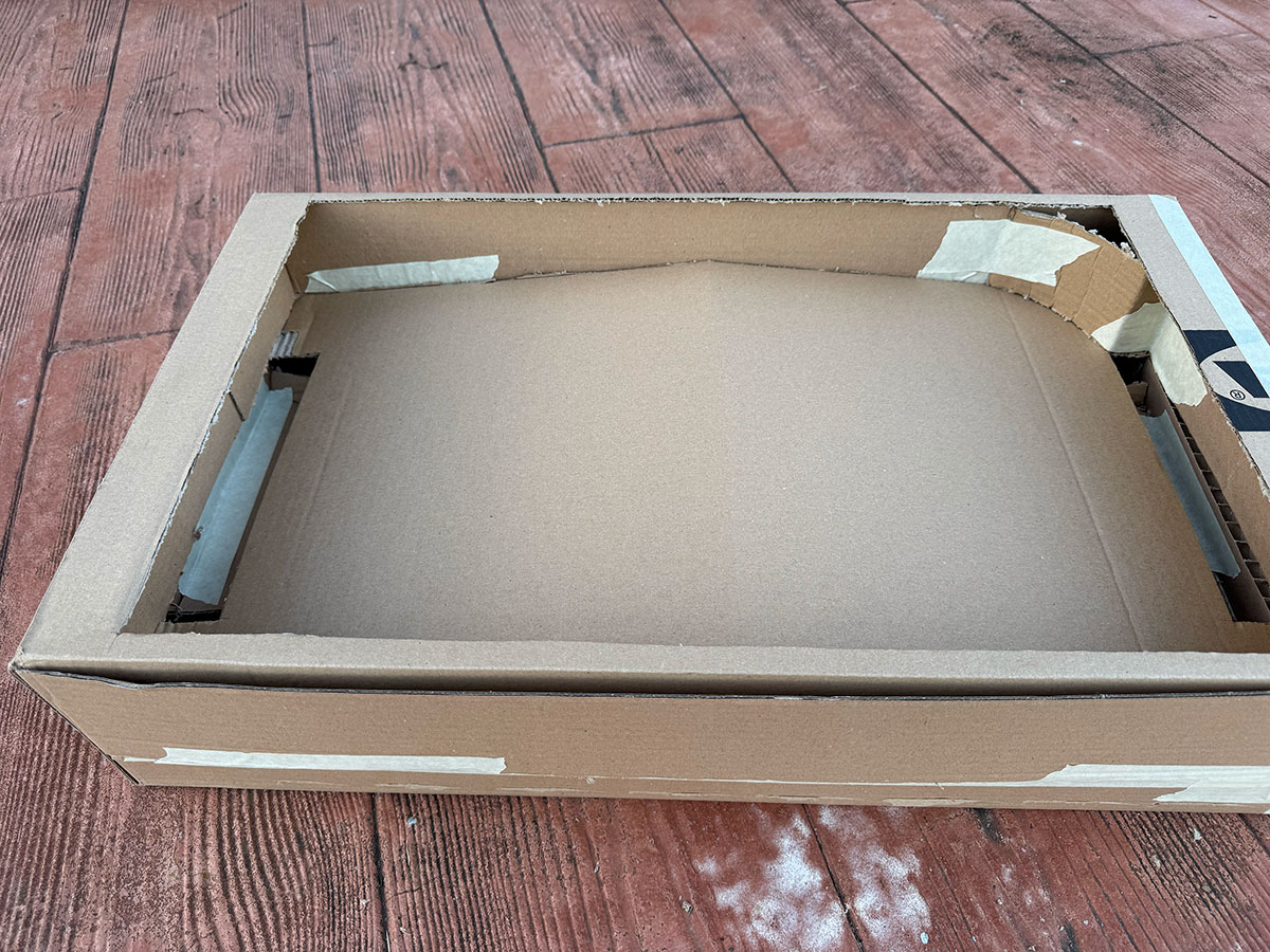
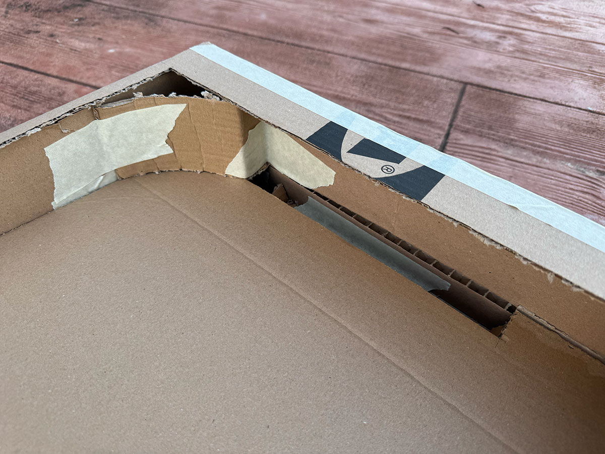
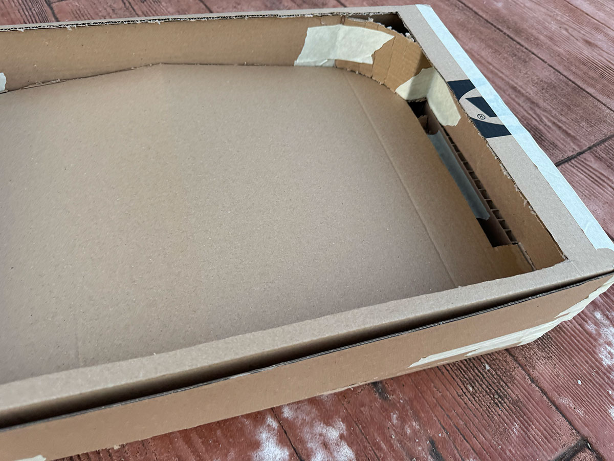
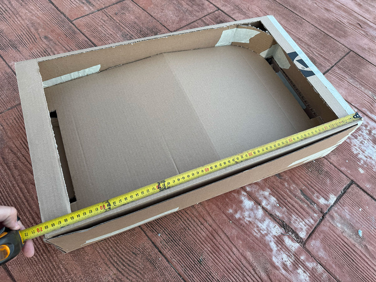
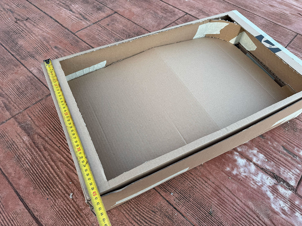
Cardboard Model
One of the things I did was divide it into two parts: the top part will be the playing area, and the bottom part will house the ball routing system so it can return to the starting position. There's also plenty of space to accommodate all the electronics.
Size: 70x40 cm
Cardboard first model (size: 0 Kb).Cardboard first model (size: 0 Kb).Cardboard first model (size: 0 Kb).Cardboard first model (size: 0 Kb).Cardboard first model (size: 0 Kb).
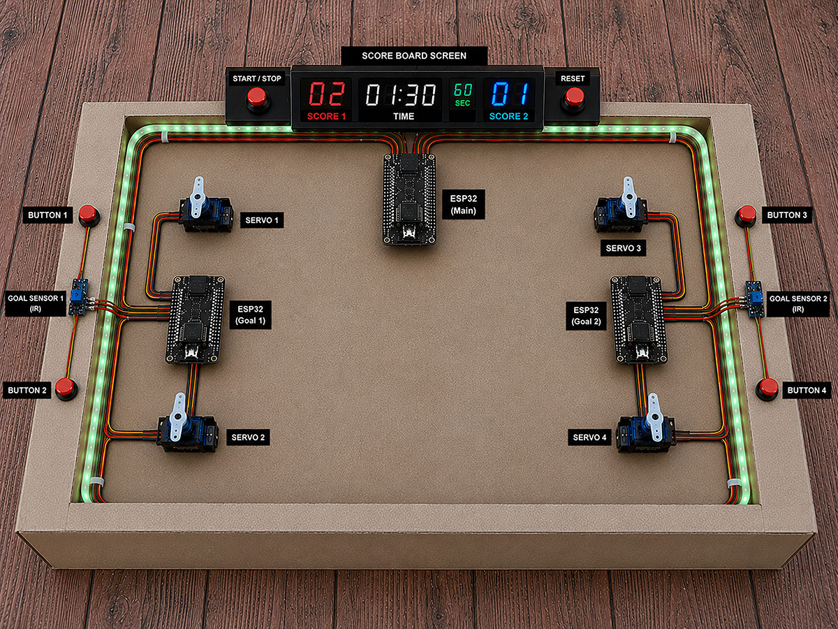
Creating the cardboard model has allowed me to consider, on a physical scale, how to integrate the elements, as well as the overall dimensions.
Skeetch over carboard model -AI Generated- (size: 0 Kb -click to enlarge-).
ChatGPT Skeetch over carboard model PromptShow prompt
English
Use the provided base image of a rectangular tabletop soccer field / mini arena as the main background. Keep the slightly angled top-down isometric perspective. Overlay realistic electronic components and technical labels to create a conceptual ESP32-based IoT system visualization.
Visual style
* Realistic 3D render combined with technical overlay.
* Photorealistic electronic components.
* Clean organized wiring.
* Modern black labels with white text.
* Soft professional lighting.
* 4:3 aspect ratio.
* High resolution.
* Maker / engineering prototype presentation style.
Elements to place on top of the base image
Top center
Add a modern black digital scoreboard with:
* Red and blue LED displays.
* Text:
* SCORE 1
* TIME
* SCORE 2
* Center timer “01:30”.
* Left red score “02”.
* Right blue score “01”.
* Small “60 SEC” indicator.
On both sides of the scoreboard:
* Red START / STOP button on the left.
* Red RESET button on the right.
Below the scoreboard:
* One main ESP32 board labeled:
* “ESP32 (Main)”
Inner field borders
Add green RGB LED strips running around the inner perimeter of the field.
Left side
Add:
* One ESP32 labeled “ESP32 (Goal 1)”.
* Two servo motors:
* “SERVO 1”
* “SERVO 2”
* Two red push buttons:
* “BUTTON 1”
* “BUTTON 2”
* One blue IR sensor:
* “GOAL SENSOR 1 (IR)”
Connect everything using red, yellow, and black wires.
Right side
Add:
* One ESP32 labeled “ESP32 (Goal 2)”.
* Two servo motors:
* “SERVO 3”
* “SERVO 4”
* Two red push buttons:
* “BUTTON 3”
* “BUTTON 4”
* One blue IR sensor:
* “GOAL SENSOR 2 (IR)”
Connect everything using red, yellow, and black wires.
Wiring
* Wires should follow the inner border of the field.
* Clean and aesthetically organized routing.
* Smooth realistic curves.
* Clearly show connections between ESP32 boards, sensors, and servos.
Labels
* Small black boxes with white text.
* Minimal technical style.
* Positioned near each component.
Expected result
The final image should look like:
* a real functional prototype,
* a professional engineering presentation,
* a Fab Lab / ESP32 / IoT technical mockup,
* a hybrid between industrial render and interactive system diagram.
Español
Usa la imagen base proporcionada de una mesa/campo rectangular tipo futbolín o mini cancha como fondo principal. Mantén la perspectiva superior ligeramente inclinada (isométrica suave). Encima de la imagen, agrega componentes electrónicos y etiquetas técnicas realistas para crear una visualización conceptual de un sistema IoT basado en ESP32.
Estilo visual
* Render 3D realista combinado con overlay técnico.
* Componentes electrónicos fotorealistas.
* Cableado limpio y organizado.
* Etiquetas negras modernas con texto blanco.
* Iluminación suave y profesional.
* Aspect ratio 4:3.
* Alta resolución.
* Estilo maker / engineering prototype presentation.
Elementos a agregar sobre la imagen base
Parte superior central
Agregar un marcador digital negro moderno con:
* Display LED rojo y azul.
* Texto:
* SCORE 1
* TIME
* SCORE 2
* Timer central “01:30”.
* Score izquierdo rojo “02”.
* Score derecho azul “01”.
* Indicador pequeño “60 SEC”.
A los lados del marcador:
* Botón START / STOP rojo a la izquierda.
* Botón RESET rojo a la derecha.
Debajo del marcador:
* Un ESP32 principal etiquetado:
* “ESP32 (Main)”
Laterales internos del campo
Agregar tiras LED RGB verdes recorriendo el borde interior del campo.
Lado izquierdo
Agregar:
* Un ESP32 etiquetado “ESP32 (Goal 1)”.
* Dos servomotores:
* “SERVO 1”
* “SERVO 2”
* Dos botones rojos:
* “BUTTON 1”
* “BUTTON 2”
* Un sensor IR azul:
* “GOAL SENSOR 1 (IR)”
Conectar todo con cables rojo, amarillo y negro.
Lado derecho
Agregar:
* Un ESP32 etiquetado “ESP32 (Goal 2)”.
* Dos servomotores:
* “SERVO 3”
* “SERVO 4”
* Dos botones rojos:
* “BUTTON 3”
* “BUTTON 4”
* Un sensor IR azul:
* “GOAL SENSOR 2 (IR)”
Conectar todo con cables rojo, amarillo y negro.
Cableado
* Los cables deben seguir el borde interior del campo.
* Organización limpia y estética.
* Curvas suaves y realistas.
* Mostrar claramente conexiones entre ESP32, sensores y servos.
Etiquetas
* Cajas negras pequeñas con texto blanco.
* Estilo técnico minimalista.
* Colocadas cerca de cada componente.
Resultado esperado
La imagen final debe parecer:
* un prototipo funcional real,
* una presentación profesional de ingeniería,
* un mockup técnico para Fab Lab / IoT / ESP32 project,
* mezcla entre render industrial y diagrama interactivo.
The schedule is presented as a Gantt diagram that shows how the project will be developed over time.
Tasks are distributed across the remaining weeks until the final deadline, allowing a clear view of the timeline and workload.
This planning helps to track progress, prioritize tasks, and ensure that the project is completed on time.
gantt
title Final Project Development Plan
dateFormat YYYY-MM-DD
axisFormat %d-%m
todayMarker off
section Planning
Project scope definition :done, a1, 2026-05-06, 1d
System diagram :done, a2, 2026-05-07, 1d
Task breakdown :active, a3, 2026-05-08, 2d
section Design
Design review : b1, 2026-05-10, 1d
CAD development : b2, 2026-05-11, 2d
Component validation : b3, 2026-05-13, 1d
section Fabrication
Parts manufacturing : c1, 2026-05-14, 3d
Digital fabrication processes : c2, 2026-05-14, 3d
Assembly preparation : c3, 2026-05-17, 2d
section Integration
Mechanical assembly : d1, 2026-05-19, 3d
Electronics integration : d2, 2026-05-21, 3d
Wiring and calibration : d3, 2026-05-24, 2d
section Programming
Firmware / software development : e1, 2026-05-26, 3d
Functional testing : e2, 2026-05-29, 2d
Prototype validation :milestone, e3, 2026-05-31, 1d
section Refinement
Debugging : f1, 2026-06-01, 2d
Iteration and improvement : f2, 2026-06-03, 2d
Final testing : f3, 2026-06-05, 1d
section Finalization
Final refinements : g1, 2026-06-06, 1d
Documentation : g2, 2026-06-06, 2d
Media production : g3, 2026-06-07, 1d
Presentation preparation : g4, 2026-06-07, 1d
Final delivery :milestone, g5, 2026-06-08, 1d
Fabrication/Production time estimate
In addition to the electronic and mechanical integration, I also wanted to estimate the approximate fabrication and production time required to build the complete system. This helps me better understand the overall scope of the project, organize the remaining development stages, and evaluate the real effort involved in manufacturing, assembly, programming, and final integration.
The following table shows an approximate time and cost estimation for the main fabrication processes involved in developing PinSocc Ball.
No.
Task
Estimated time (h)
Cost (€)
Notes
1
PCB's
2.5
PCB milling and soldering components
2
Software/firmware
0.25
Load software codes
3
CNC milling
2
Milling wood parts
4
Laser cut
1
3mm MDF laser cut
5
Laser cut
0.25
Two-layer acrylic (vector and raster)
6
3D printing
4.5
Printing all parts
7
Assembly
2.5
Full assembly all parts
Total estimated fabrication time
Week questions/tasks
✔
Individual assignment:
made a plan for system integration for your final project?
documented your plan with CAD and/or sketches for system integration?
implemented methods of packaging?
designed your final project to look like a finished product?
documented system integration of your final project?
linked to your system integration documentation from your final project page?
Done
Final reflection
This week helped me understand that a big part of the project is not only about fabricating parts or programming components, but about making everything work together in a coherent and fluid way.
Both the cardboard model and the user experience and system architecture diagrams are the result of the tests, mistakes, and lessons learned during the previous weeks of Fab Academy.
Little by little, PinSocc Ball starts to feel less like an experimental prototype and more like a real game experience, where every mechanical, electronic, and visual element becomes part of the same integrated system.
Credits
All texts were written in Spanish and translated into English using Google Translate and ChatGPT.