Mechanical Design, Machine Design
2026 FabLab León Node (Spain)
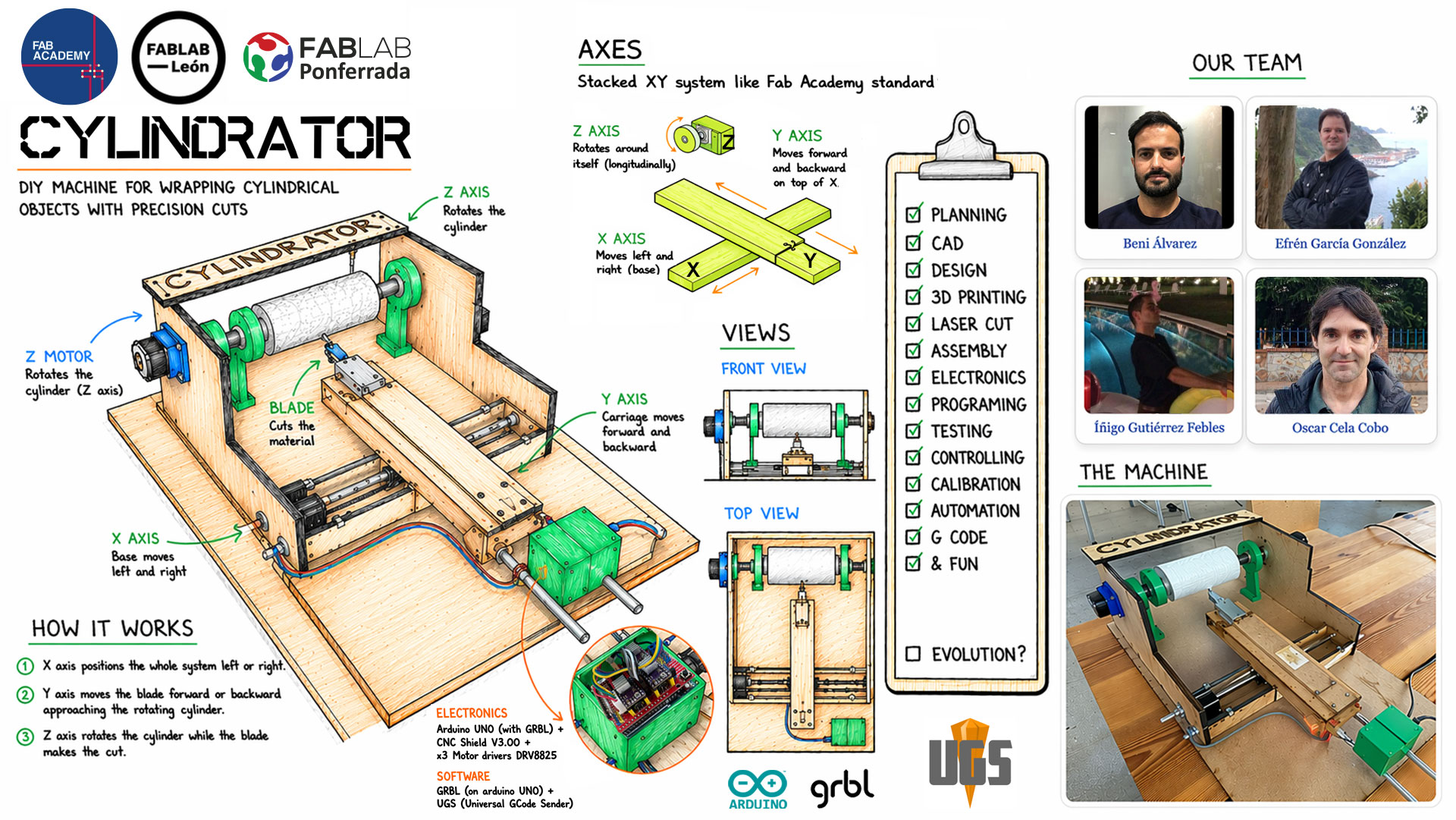
Team members


Slide
Video
High quality video available on Vimeo ↗️.
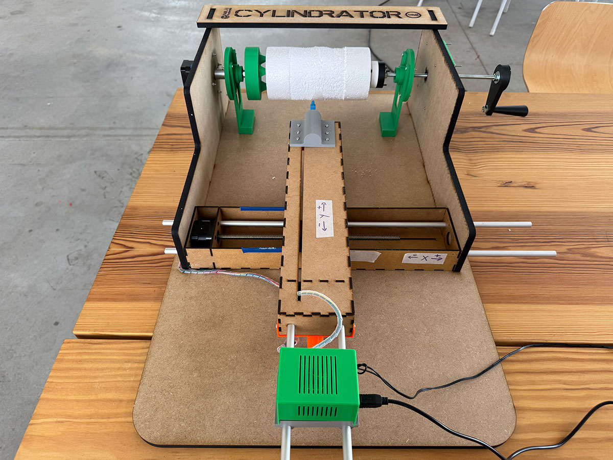
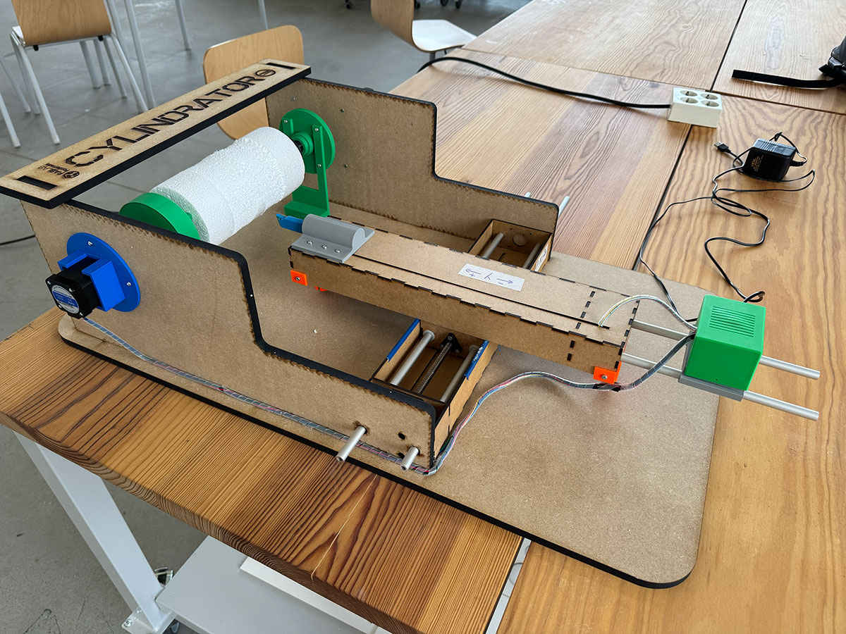
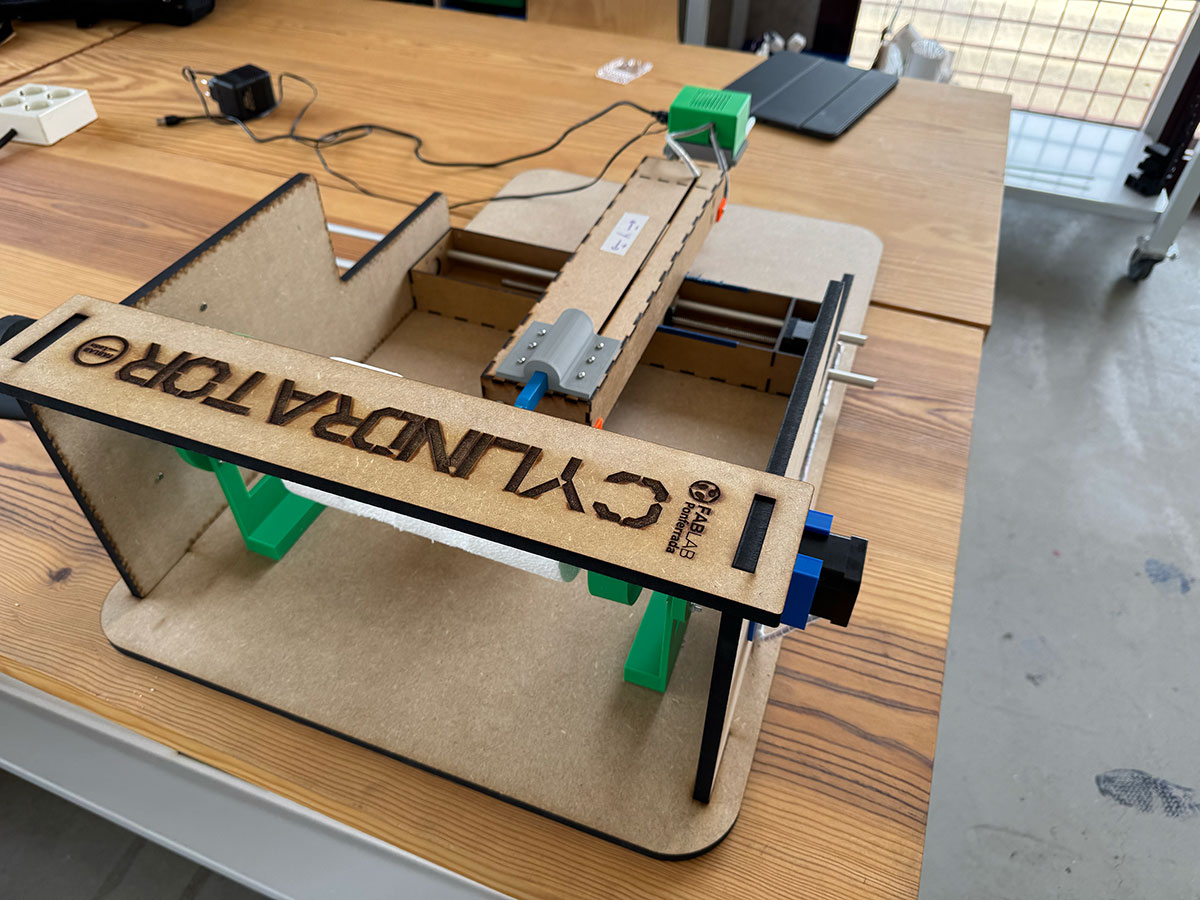
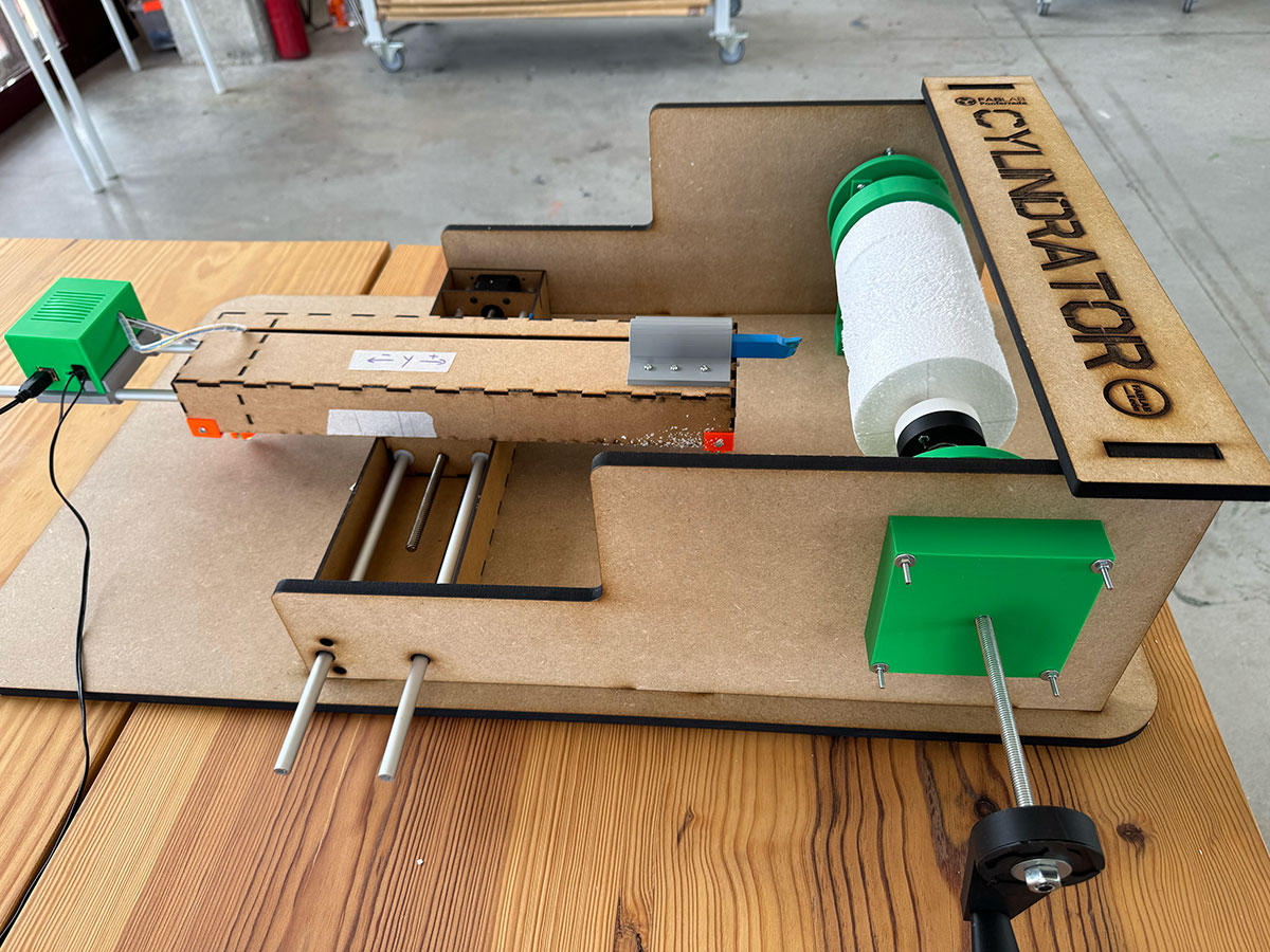
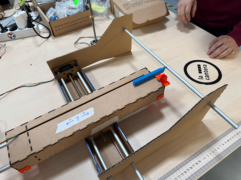
CYLINDRATOR The machine (final photos)
Documentation
Design a machine that includes mechanism + actuation + automation + application
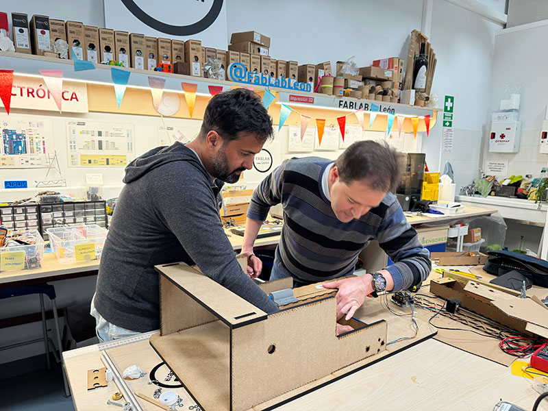
This week gave us the opportunity to take a step further and face a much more complete challenge: designing, building, and programming a functional machine as a team.
After considering different options at the beginning of the week, and with the guidance of our instructors at Fab Lab León, we decided to take as a starting point one of the machines developed by Fab Lab Milan Opendot in FabAcademy 2015 ↗️, which simulates the operation of a lathe. We found it to be a very interesting reference, not only because of the concept itself, but also because it allowed us to better understand the relationship between mechanics, electronics, and control.
Starting from that reference, our goal was not simply to replicate it, but to evolve and improve some of its parts, adapting the machine to our needs and to the resources available. At the same time, we wanted to document the whole process as completely as possible, making sure we understood each decision we took during the development.
From a technical point of view, the machine is based on a three-axis system controlled by stepper motors. In our case, we used three stepper motors for the X, Y, and Z axes. One of the main differences compared to the original Opendot design is that we replaced the drill they used to generate the rotation of the Z axis with a third stepper motor. This gives us greater control over the movement and makes the integration with the control system much more consistent.
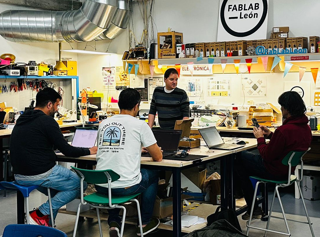
In terms of teamwork, although all of us were globally involved in the project, following and contributing to every stage, we also divided some tasks in order to optimize time. This allowed us to move forward in parallel on different areas such as design, fabrication, and electronics, while maintaining a shared vision of the project and ensuring the active participation of all team members across all areas.
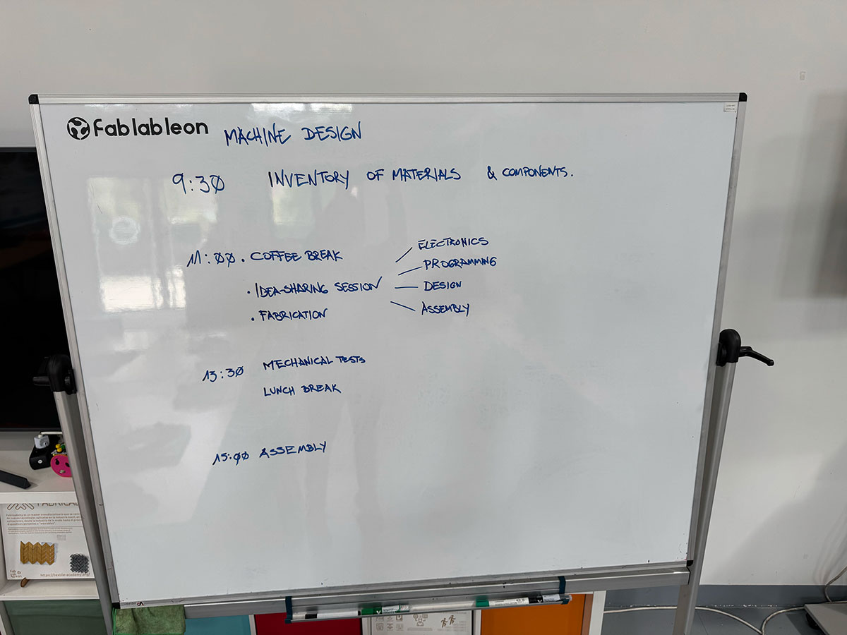
Project task planning
| Task | Responsible |
|---|---|
| Planning | Team & Local instructor |
| CAD | Óscar & Efrén |
| 2D Design | Efrén & Óscar |
| 3D Design | Íñigo & Óscar |
| 3D Printing | Íñigo & Beni |
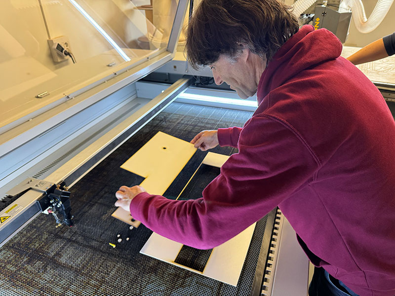
| Laser Cut | Beni & Efrén |
| Assembly | Beni & Efrén |
| Electronics | Íñigo |
| Programming | Óscar |
| Testing | Team |
| Controlling | Team |
| Calibration | Team |
| Automation | Team |
| G-code | Team |
| Slide & Video | Beni |
| Fun 😄 | All (Team & instructors) |
Build the mechanical parts and operate it manually
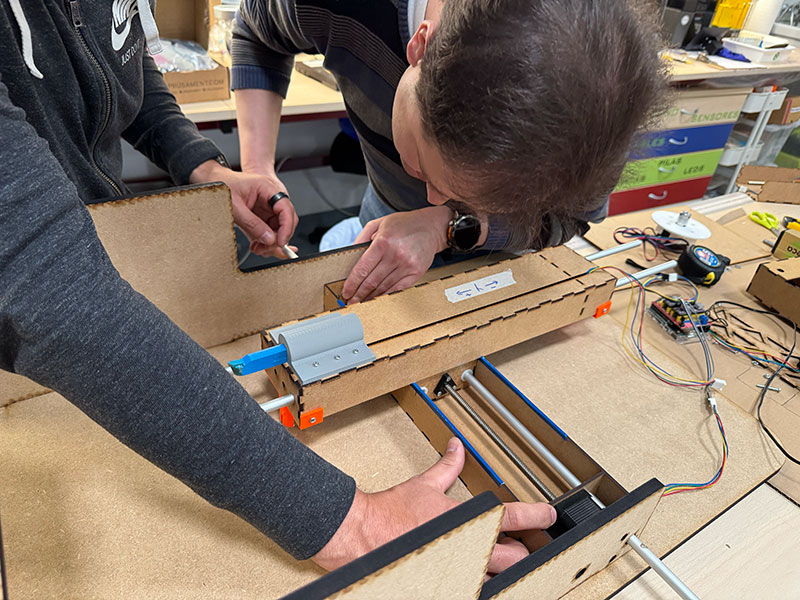
X&Y Axis
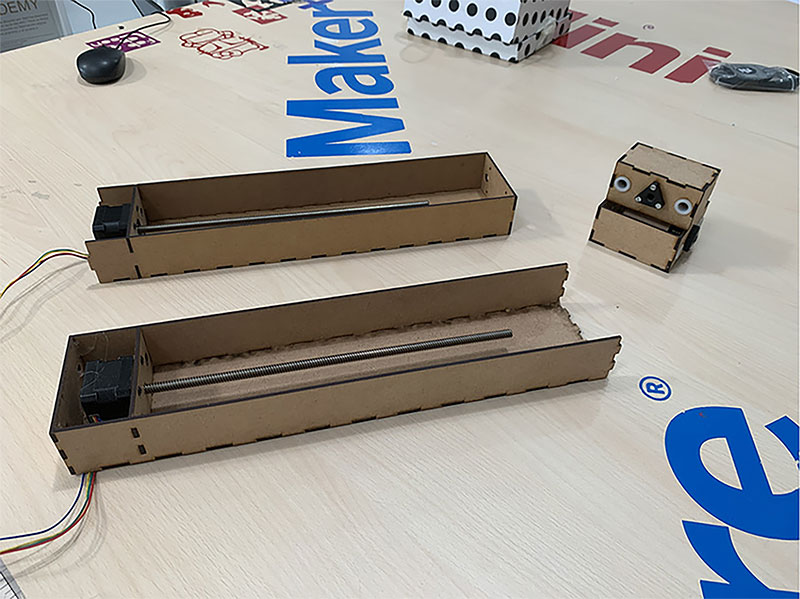
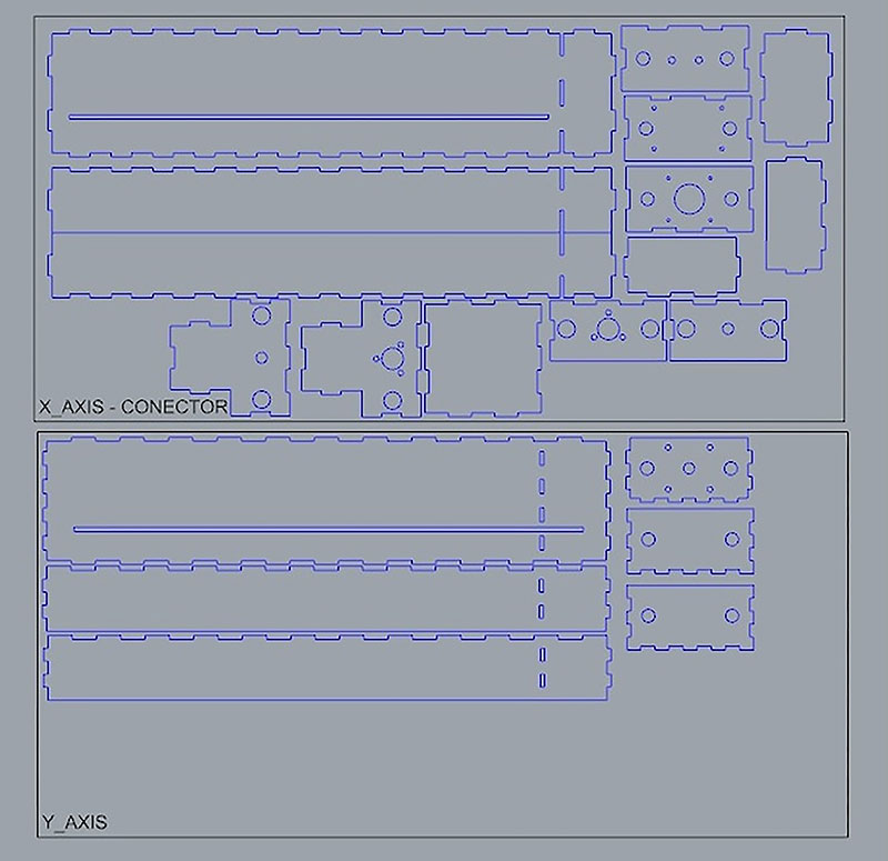
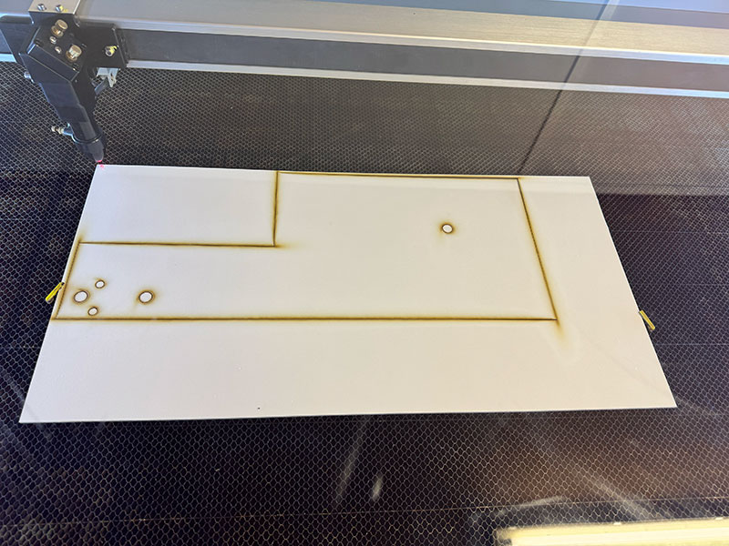
For the mechanical design of the X and Y axes, we started from an existing base available at Fab Lab León: the modules developed in 2020 for the LE-CAR-BIL MACHINE (FabAcademy 2020) ↗️ by Adrián, Iván, Álvaro, and Lola.
These modules felt like a very solid starting point, as they provide a simple and effective solution for two-axis movement using a compact structure. They are made of 3 mm MDF and use a connection system between both axes based on joints downloaded from Nadya Peek’s MTM page, allowing the X and Y movements to be integrated in a coordinated way.
Another advantage of this design is that each module houses its own stepper motor inside, which simplifies the mechanical integration and keeps the overall system clean and well organized.
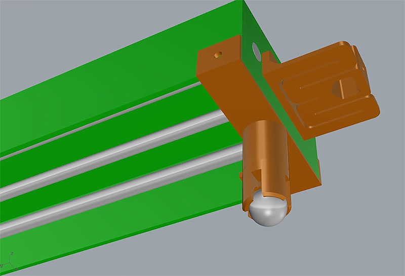
One interesting aspect of this design is that part of the Y axis becomes suspended during its movement. To solve this, the original 2020 design included a mobile support system based on small balls, inspired by the educational robot Escornabot. This system provides support when the Y axis reaches the extreme positions of its travel, adding stability without restricting movement.
Starting from this base, our work focused on adapting these modules to our machine, understanding how they work, and evaluating which parts we could keep and which ones needed to be modified in order to integrate them with the rest of the system.
X&Y AXES MECHANICAL VIDEO MOVEMENT
Z Axis development
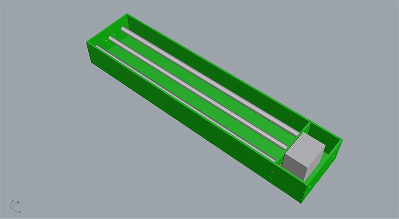
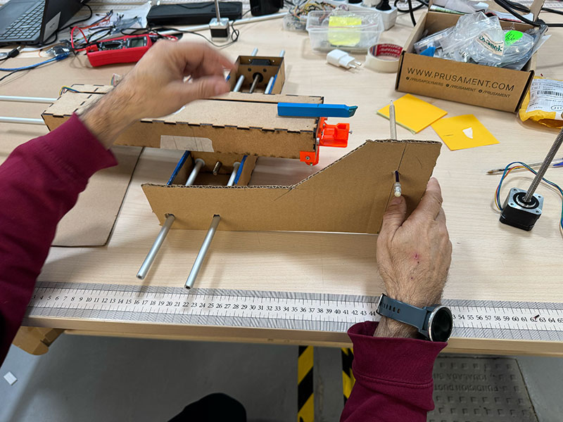
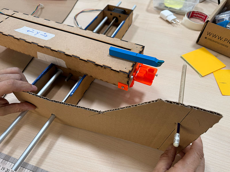
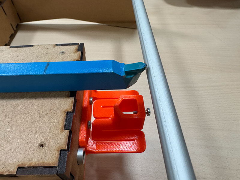
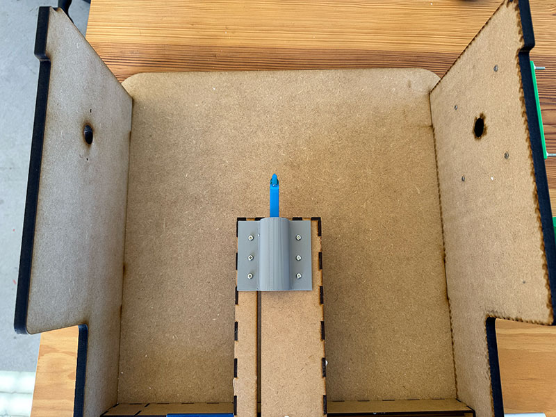
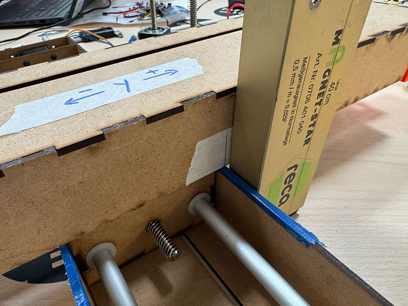
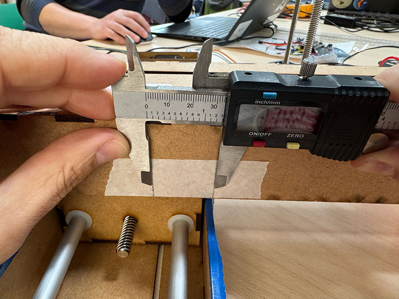
For the development of the Z axis, we started with a very simple but essential step: building an initial mockup using cardboard pieces. These pieces mainly represented the two side supports connecting the X axis to the Z axis.
The goal of this mockup was to accurately define the height of the Z axis, making sure it aligned perfectly with the tip of the cutting blade mounted on the Y axis. This adjustment was critical, as even small deviations would directly affect the machine’s performance and cutting accuracy.
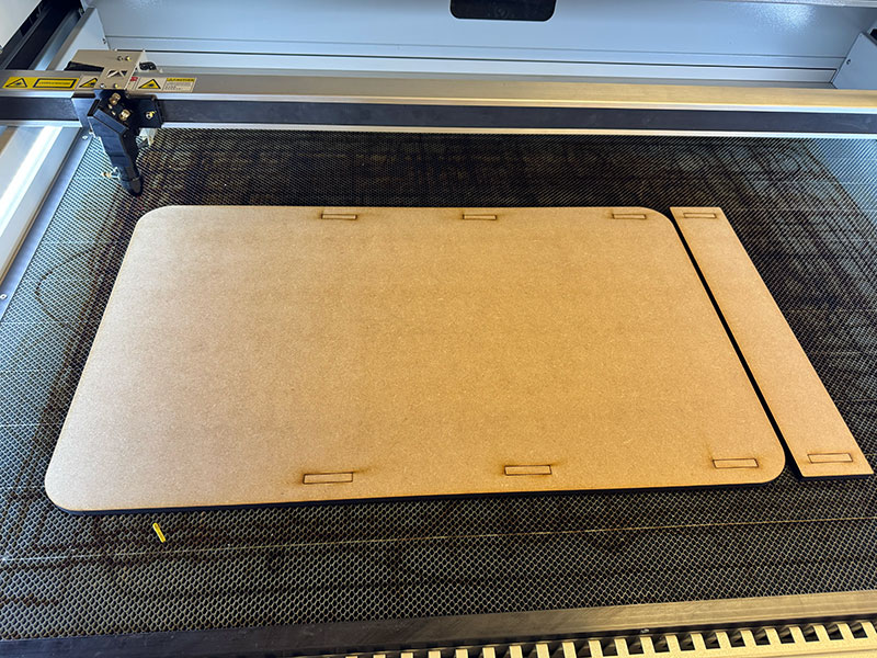
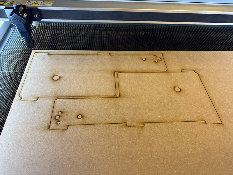
Once we obtained the correct measurements, we moved on to fabricating the parts using 3 mm MDF. However, after assembling the structure, we quickly realized that it did not provide enough stability. The material flexed too much, and the lack of rigidity negatively impacted the behavior of the axis, especially during movement.
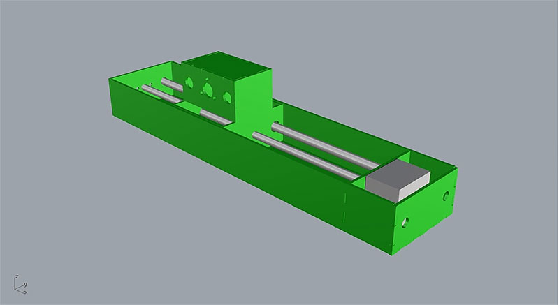
At that point, we decided to redesign the structure. We added both a bottom base and a top support, reinforcing the entire Z axis assembly. In addition, we switched to a thicker material, using 10 mm MDF, which significantly improved the rigidity and overall consistency of the system.
With this iteration, we achieved a much more stable and reliable solution, suitable for the real operation of the machine.
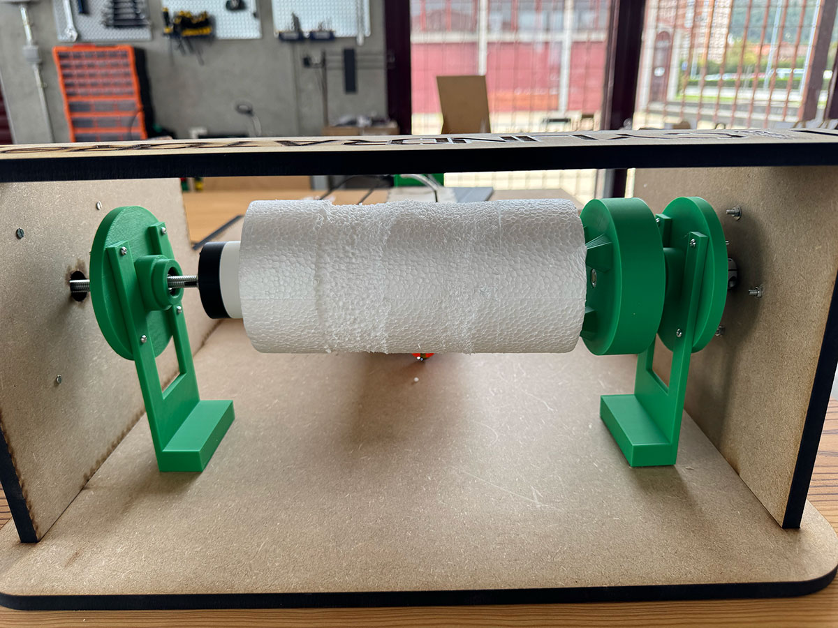
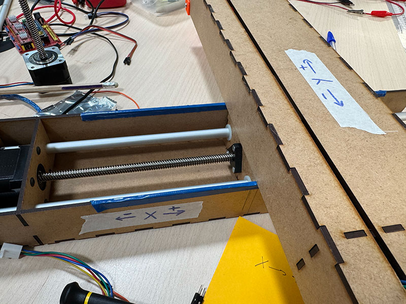
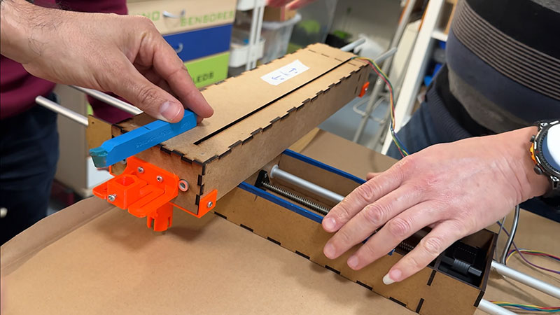
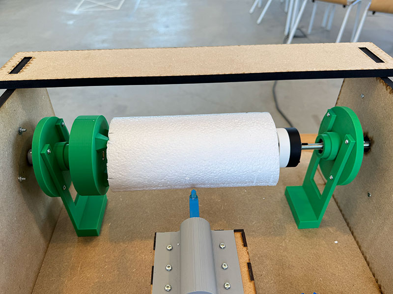
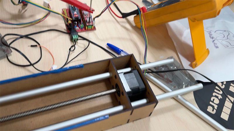
Since the Z axis acts as the rotational axis, it required a specific system to hold the material securely. We needed to design supports that could fix the piece by pressure, while also allowing adjustment to accommodate different lengths.
To solve this, we designed an asymmetrical system: the motor side (left) remains fixed, while the opposite side (right) is adjustable. This allows us to adapt the distance between both ends depending on the size of the material being used.
In the previous days, we 3D printed several parts from the OpenDot 2015 designs. Although we did not use all of them, many of these parts were useful either as references or directly integrated into our system.
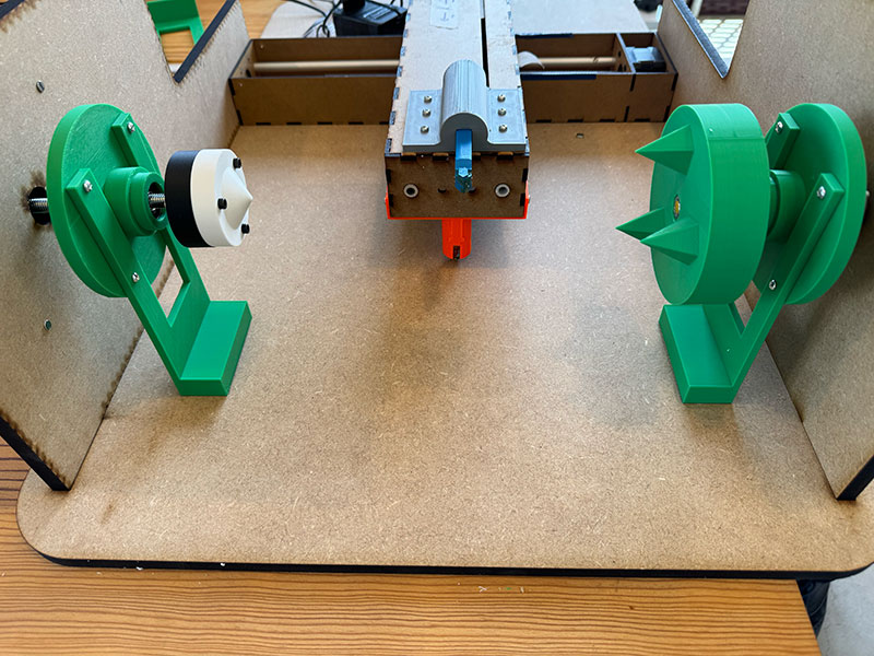
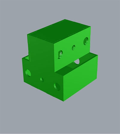
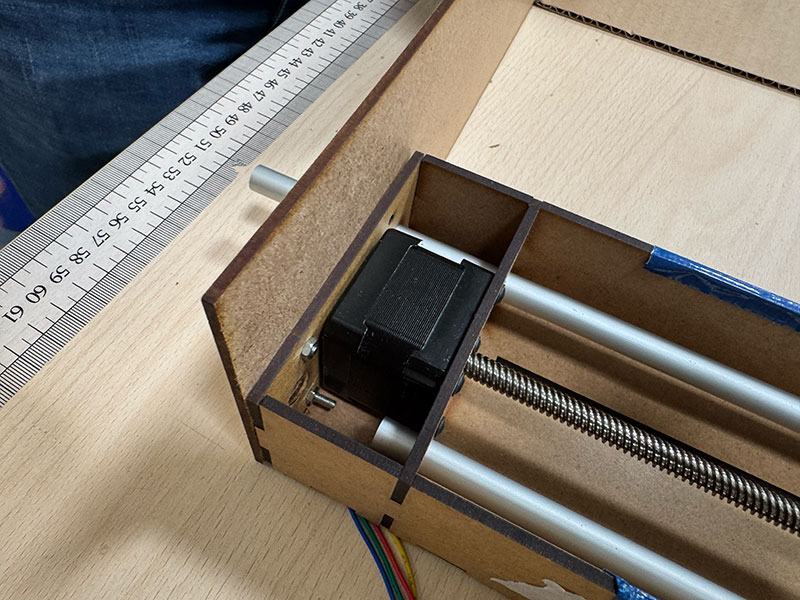
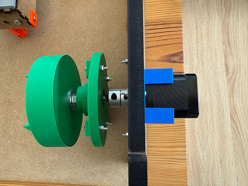
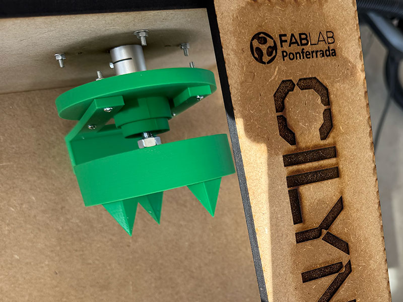
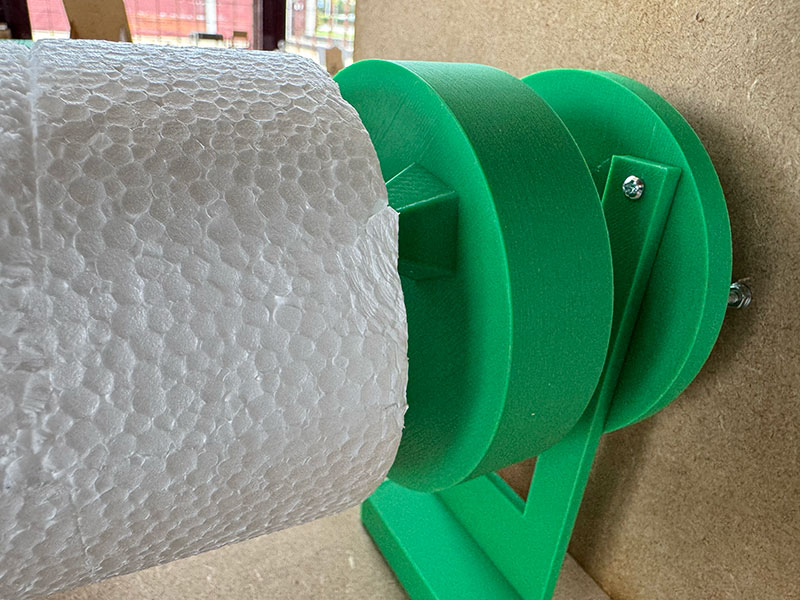
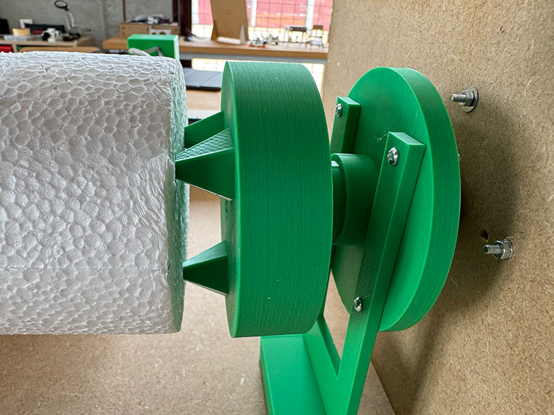
Z AXIS LEFT SIDE DETAILS
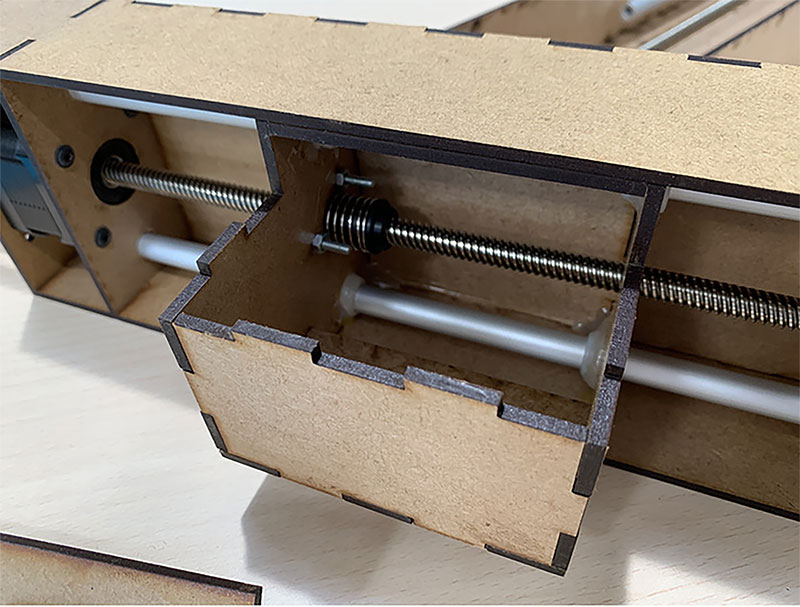
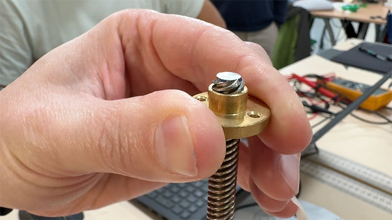
On the motor side, we designed a dedicated support for the Z axis stepper motor. We added a NEMA17 coupling connected to an 8 mm shaft, which links to a threaded rod. This rod is cut to the required length and adjusted using a nut near the material fixation area.
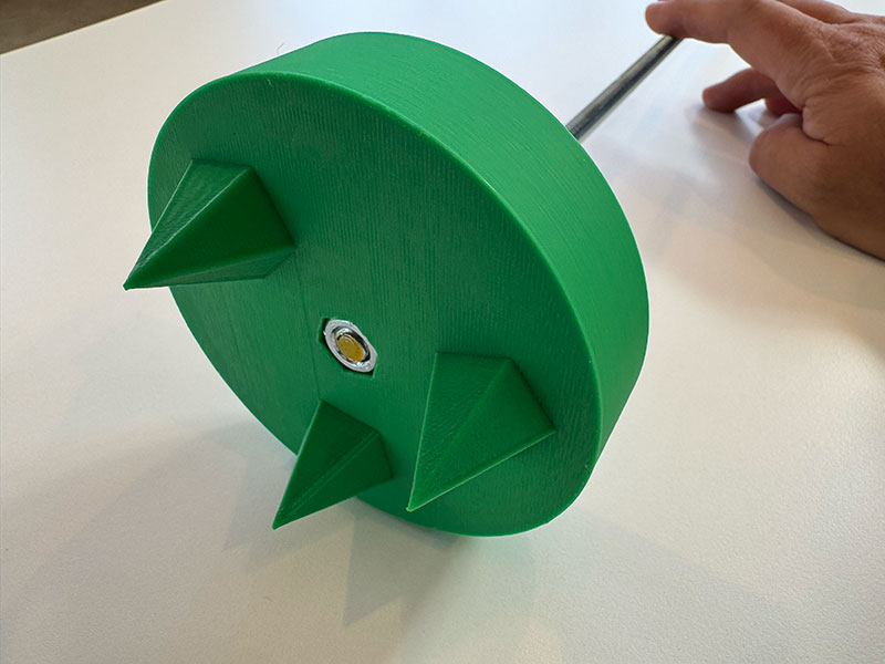
On the opposite side, we used a 3D printed part designed to hold the material by pressure. This piece includes small spikes that slightly penetrate the surface of the material, preventing it from slipping during rotation.
With this system, we achieved a firm yet adaptable fixation, allowing us to work with materials of different sizes without redesigning the structure.
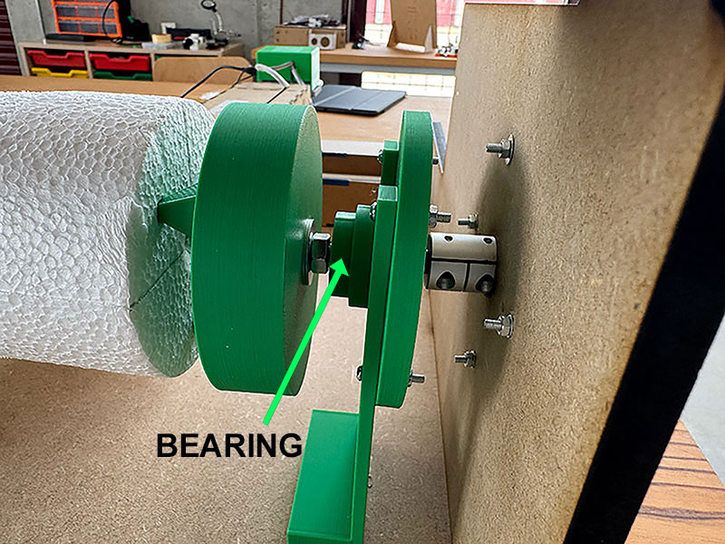
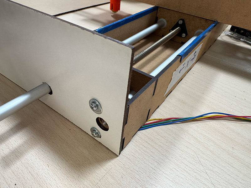
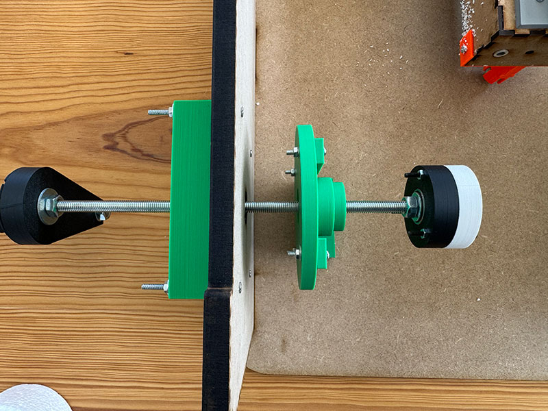
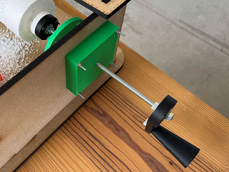
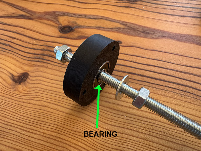
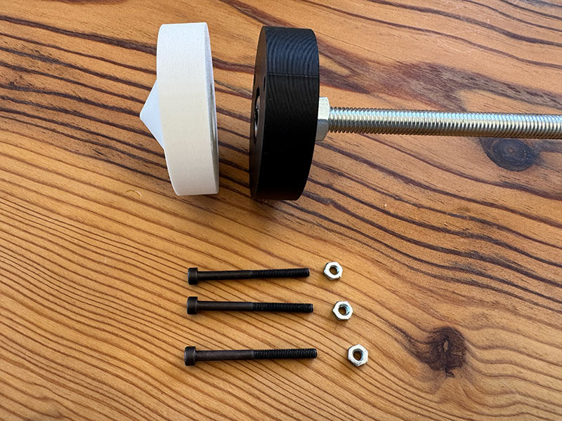
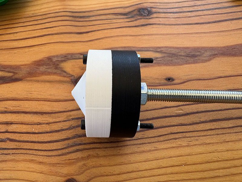
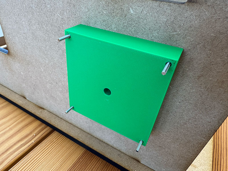
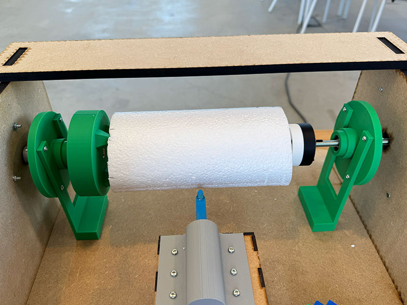
Z AXIS RIGHT SIDE DETAILS
On the opposite side of the Z axis, we also reused and adapted some of the 3D designs from OpenDot 2015 to fit our needs.
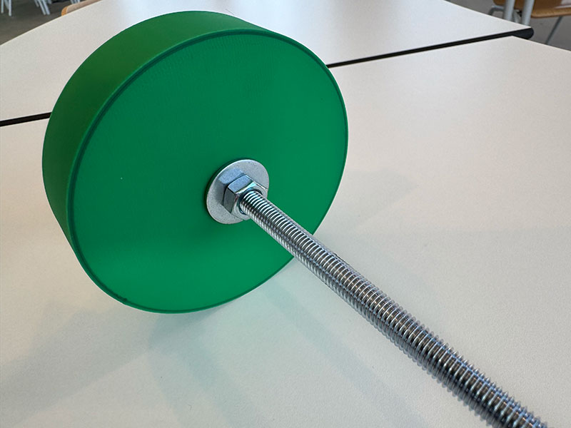
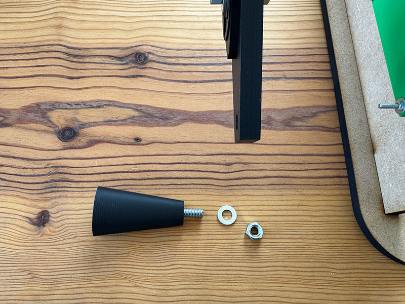
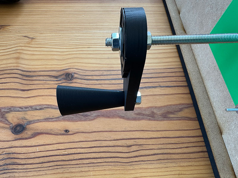
For this end, we used an 8 mm threaded rod with enough length to allow adjustment depending on the size of the material. At the outer end, we added a handle, making it easy to manually adjust and press the material against the rotating support, ensuring a proper fixation.
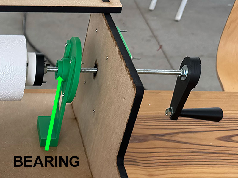
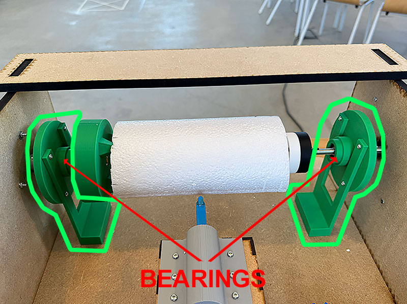
Additionally, we incorporated an extra bearing into the part that holds the material. This element is key, as it prevents the threaded rod from rotating together with the axis.
Thanks to this improvement, the Z axis can rotate freely and smoothly, avoiding unnecessary stress on the adjustment mechanism and improving the overall performance of the system.
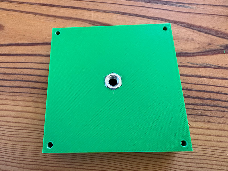
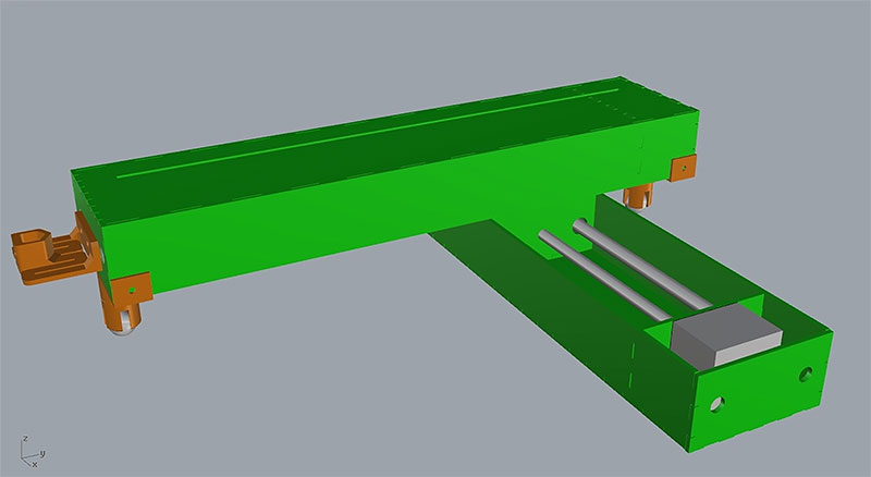
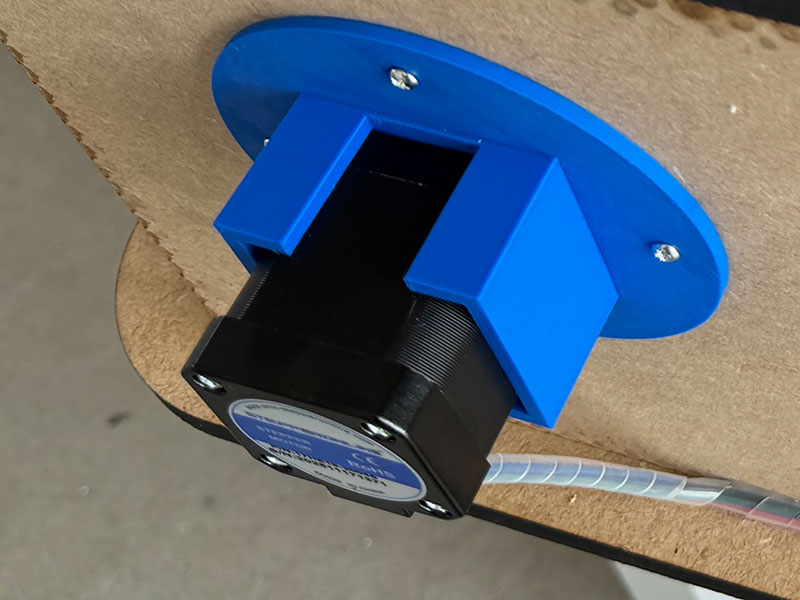
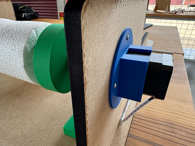
To further improve the stability of the Z axis during movement, we designed additional 3D printed parts that act as structural reinforcement elements on both sides of the axis.
As shown in the detailed images of the right and left sides of the Z axis, these parts are integrated into the overall structure, helping to better understand how stability has been addressed beyond the main components.
Their main function is to increase the rigidity of the system and act as connection points to the machine base, reducing possible flex and improving the overall behavior during rotation.
With this improvement, we achieved a more solid and consistent Z axis, especially in long operation scenarios or when working with longer materials, where even small instabilities become more critical.
Z AXIS MECHANICAL VIDEO MOVEMENT
Electronics
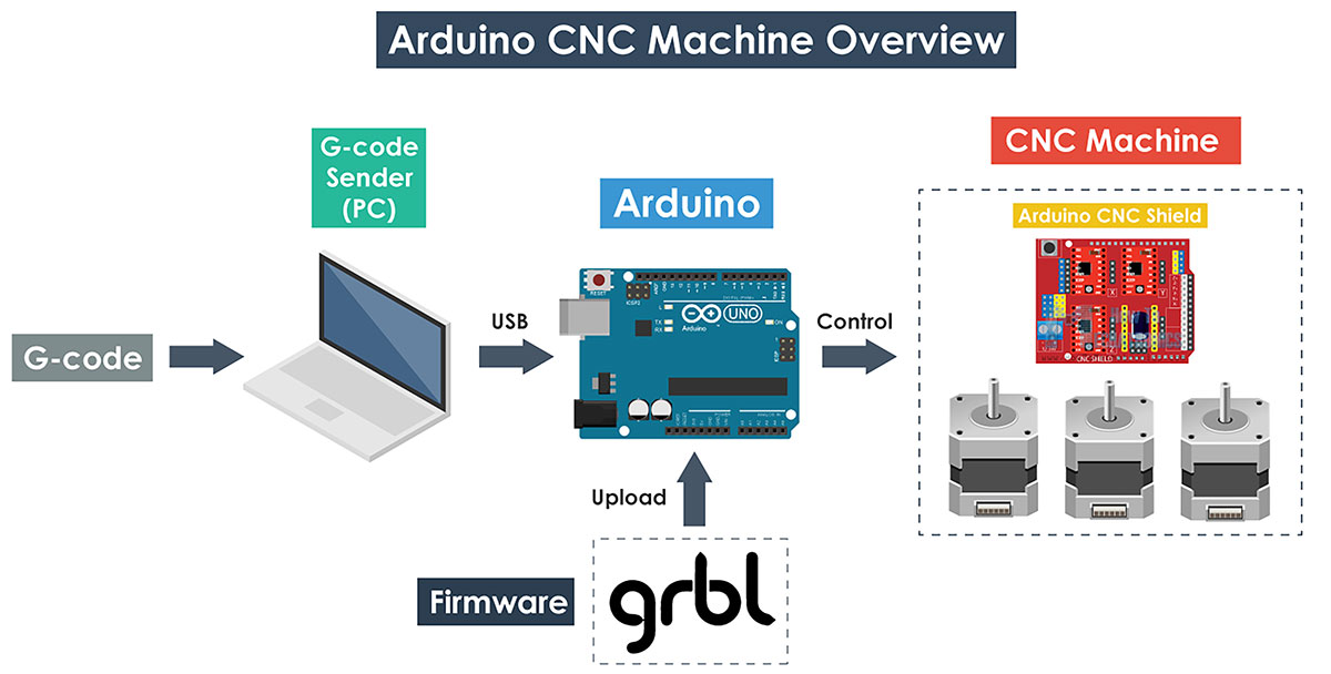
To control the machine, we decided to use GRBL, an open-source firmware that runs on an Arduino and turns it into a CNC motion controller. It interprets G-code commands and controls the stepper motors to move the machine accurately.
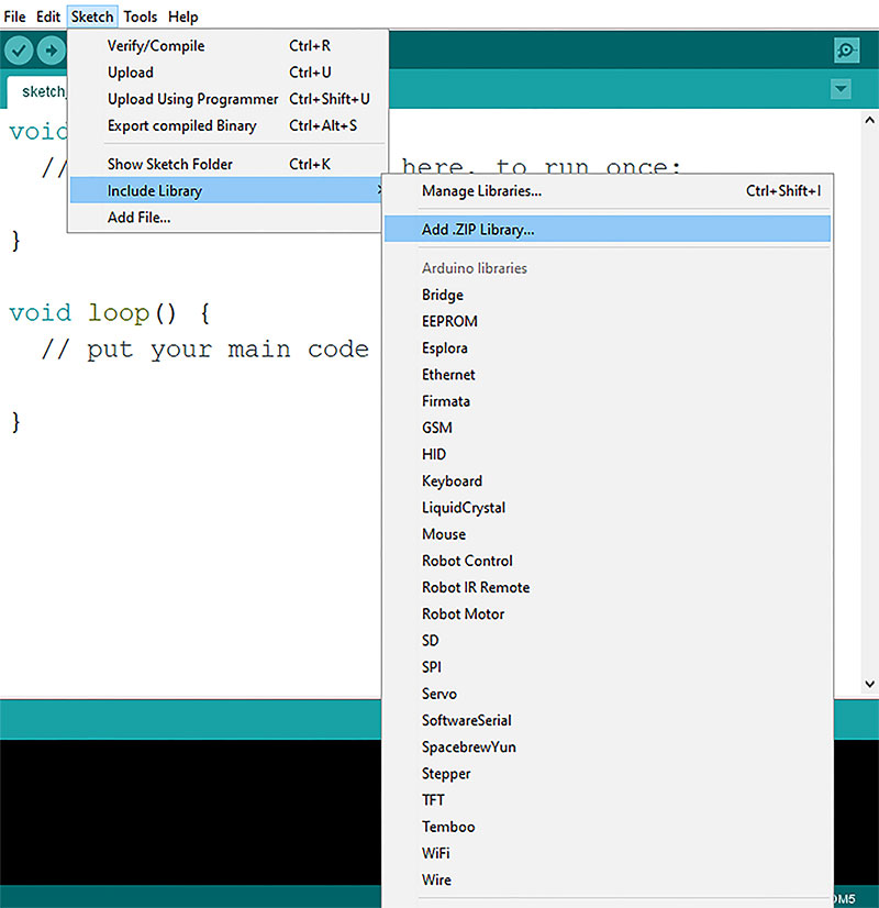
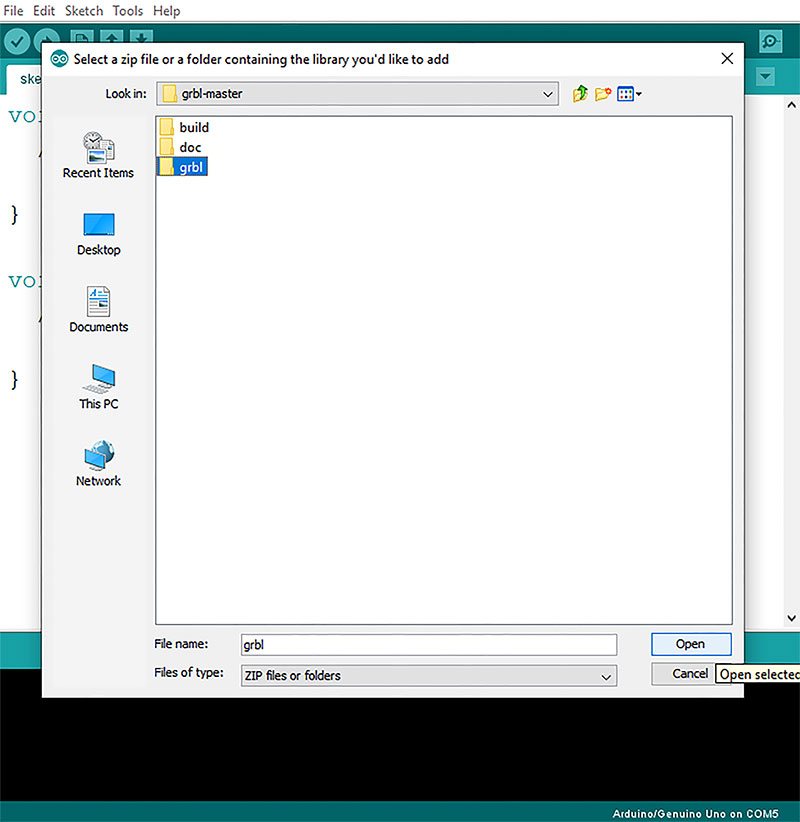
To install GRBL on our board, we followed a tutorial by Dejan (howtomechatronics.com), which explains how to install it as a library and upload the example sketch to the Arduino.
The process started by downloading the GRBL source code from its official GitHub repository and adding it to the Arduino IDE as a library. However, we encountered an issue with the .zip file, so we had to manually copy the GRBL folder into the Arduino libraries directory and restart the IDE for it to be recognized correctly.
Once this was solved, we uploaded GRBL to the board and verified its operation through the Serial Monitor, using the $$ command to display the current configuration. From there, it is possible to adjust parameters such as steps per millimeter, maximum speed, and acceleration, which become essential later during machine calibration.
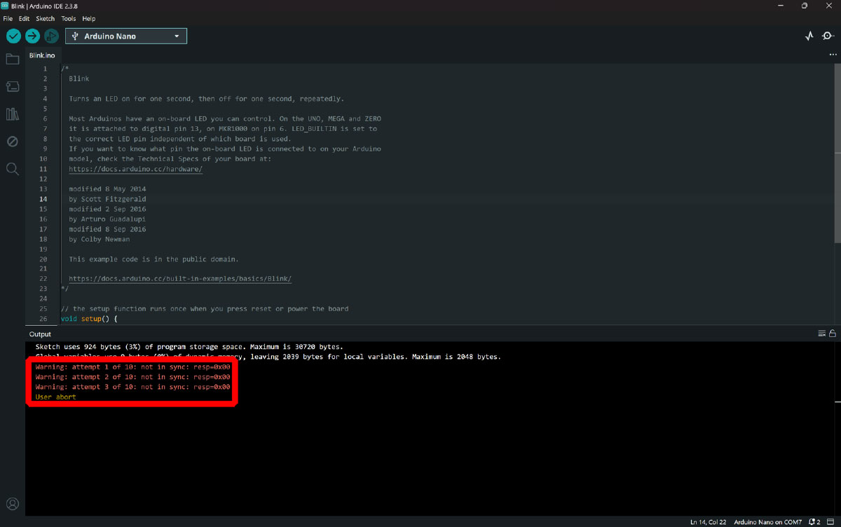
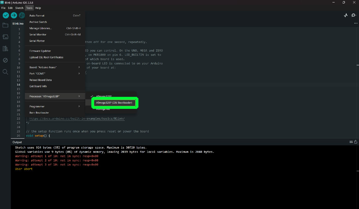
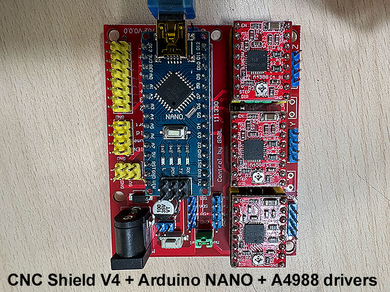
In terms of hardware, we initially started using an Arduino Nano, together with a CNC Shield V4 (HW-702_V0.0.0) and A4988 stepper drivers. At first, we even had problems uploading GRBL to the board, which we eventually solved by changing the bootloader to “ATmega328p (Old bootloader)”.
However, once this issue was fixed, we encountered a more critical problem during testing: the motors did not move. We could hear that they were powered, but they did not rotate. Initially, we suspected that the issue could be related to the drivers or the current limiting adjustment, so we performed several tests in that direction, but without success.
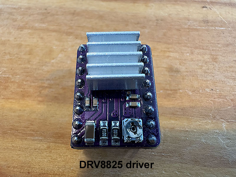
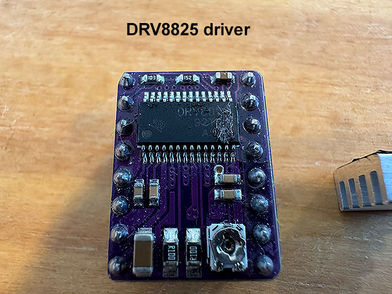
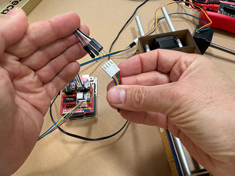
At that point, we decided to change our approach and test a different configuration using a CNC Shield V3.0. As soon as we assembled this new setup, we confirmed that the motors were working correctly. In this configuration, we used DRV8825 drivers, controlling the system through UGS (Universal GCode Sender).
To better isolate the problem, we repeated the test using the new CNC Shield V3.0 but with the previous drivers (A4988). The system worked correctly again, which allowed us to conclude that the issue was caused by the CNC Shield V4.
Based on these tests, we decided to move forward with a hardware configuration that we knew was reliable:
- Arduino UNO
- CNC Shield V3.0
- DRV8825 drivers
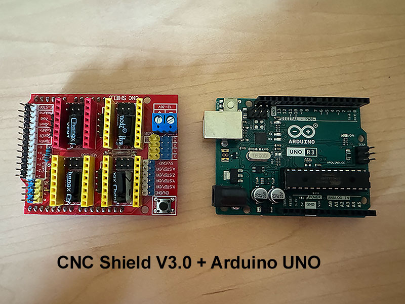
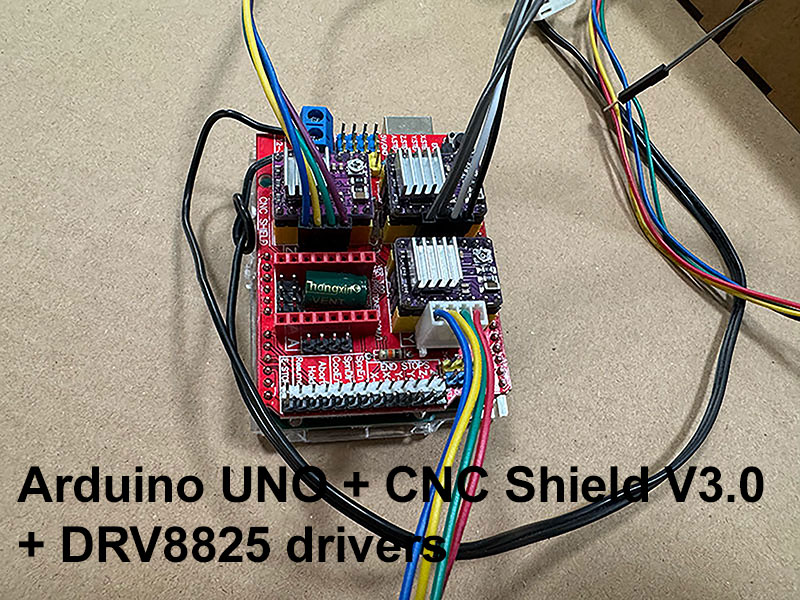
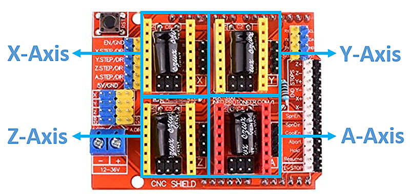
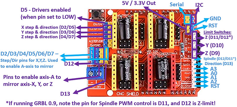
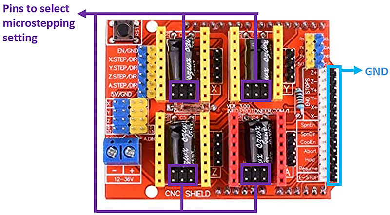
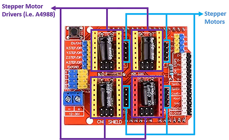
CNC Shield V3.0 details
With this setup, we were able to continue developing the machine with confidence, knowing that the electronics system was working reliably.
Control & Driver Configuration
Once GRBL is uploaded to the Arduino UNO, it requires commands from an external device to control the machine. The most common approach is to connect the board to a computer via USB and use software like UGS (Universal G-code Sender), which allows sending G-code commands and monitoring the machine in real time.
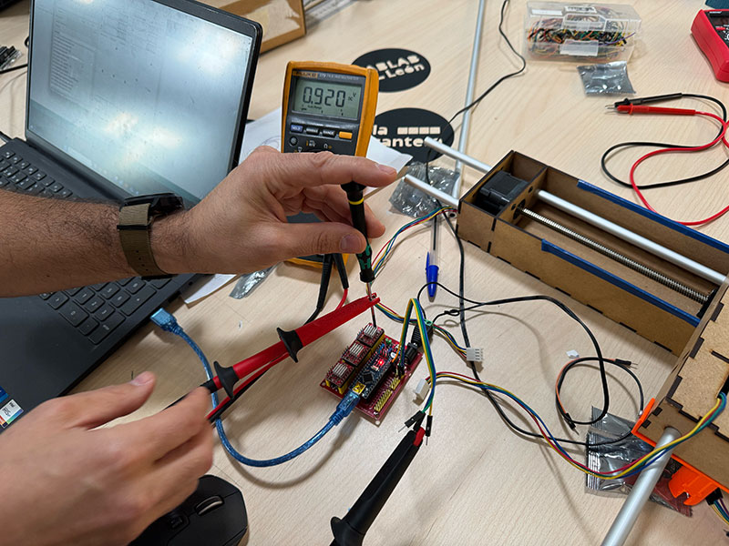
Before running the motors, it is essential to properly adjust the current limit of the drivers through the reference voltage (Vref). This step is critical both to protect the motors and to avoid damaging the drivers.
The Vref is adjusted by turning the small potentiometer on the driver while measuring the voltage with a multimeter directly on the reference point.
In our setup, we used two different types of stepper motors:
- Nema 17 RB Step Motor 17HDC1220-300N for the X and Y axes
- Nema 17 Stepperonline 17HE19-2004S for the Z axis
For the DRV8825 drivers, we used the standard relationship for carriers with 0.100 Ω sense resistors, where the current limit is defined as:
For the X and Y axes, we set the Vref to 0.92 V, which corresponds to approximately 1.84 A per phase. Since we did not have an official datasheet for these motors, we used this value as a practical and safe operating point, prioritizing stability and avoiding overheating.
For the Z axis, we used a Stepperonline 17HE19-2004S motor, specified at 2.0 A per phase and 1.3 Ω resistance. Although Ohm’s law gives an estimated phase voltage of around 2.6 V, this value is not directly used to calculate the Vref.
Instead, following the DRV8825 relationship, a current of 2.0 A would correspond to a Vref of approximately 1.0 V. In practice, we adjusted this value taking into account the real limitations of the system and its thermal behavior, keeping the configuration within a safe operating range.
This tuning process was essential to ensure a stable machine operation, avoiding both missed steps and overheating issues.
Actuate and automate your machine. Universal G-code Sender (UGS)
Once the electronics were working properly, the next step was to install and configure the control software. For this, we used UGS (Universal G-code Sender), which can be downloaded from its official website.
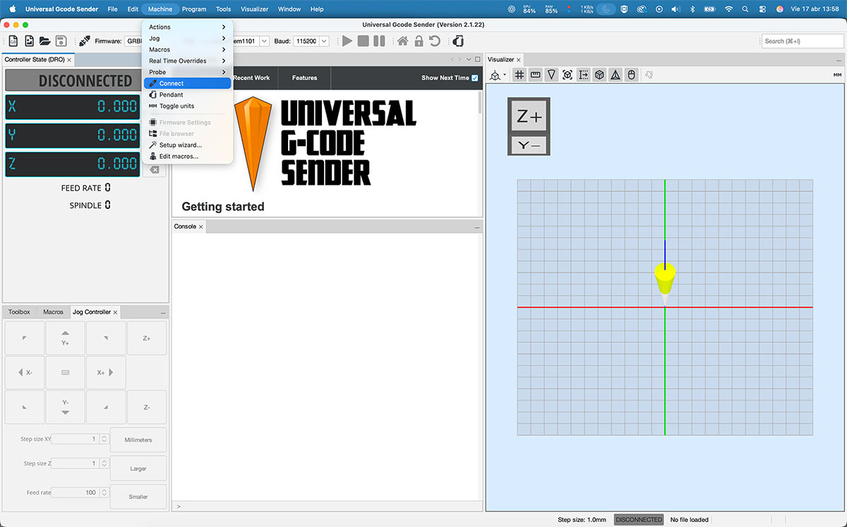
With the machine connected to both the power supply and the computer via USB, we opened UGS and accessed the setup assistant through “Machine → Setup wizard…”. This wizard helps to easily configure the system for the first time.
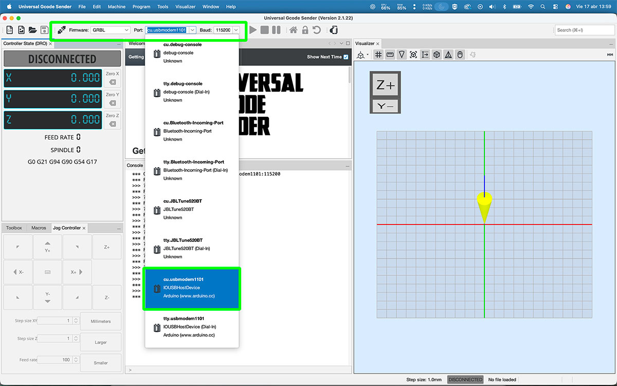
After completing the setup process, we established the connection with the machine. To do this, it is necessary to select the correct USB port, choose the GRBL firmware, and set the communication speed to 115200 baud. Once configured, we connected the system.
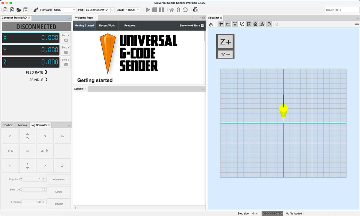
With the connection active, we used the jog controller in UGS to check how the motors responded and verify that all axes were moving correctly.
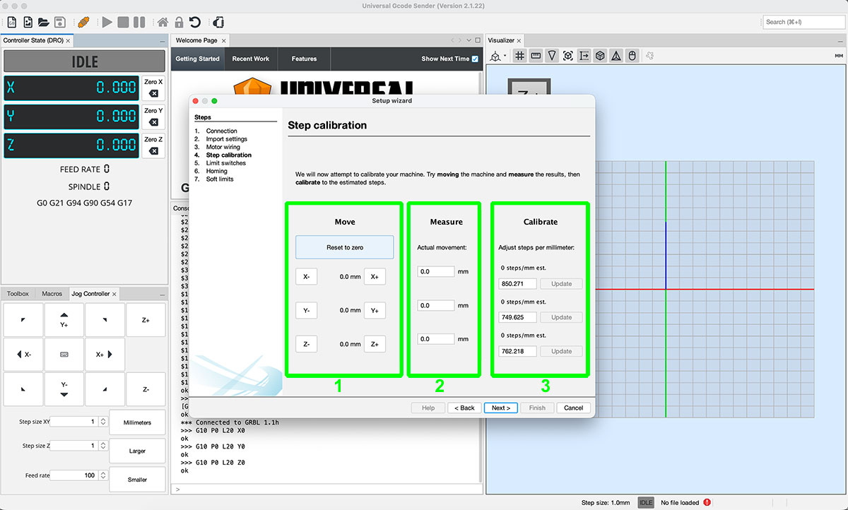
The next step was the machine calibration. For this, we used the calibration tool included in the Setup Wizard.
The process consists of entering a target movement value in one axis (for example, 10 mm) in the “Move” column. Then, we measure the actual displacement of the machine and enter that value in the “Measure” column. Based on this, the system calculates the correct steps in the “Calibrate” column, which we apply by clicking “Update”.
We repeated this same process for all three axes, ensuring accurate and consistent behavior across the entire system.
Once the machine was calibrated, we performed initial tests by running different G-code files to verify the overall functionality.
GCode test 1 Show code
- Activates [G91] (relative movements).
- Move 1: Y −1 while Z reaches 120.
- Move 2: Y +3 while Z reaches 360.
- Move 3: Y −4 while Z reaches 480.
- Move 4: X −2 while Z stays at 480.
- Move 5: Y +6 while Z reaches 720.
- Returns to [G90] (absolute positioning).
Finally, we executed a complete test G-code to validate the coordinated movement of all axes.
GCode Final test Show code
- Activates [G91] (relative movements).
- Move 1: Y −1 at feedrate 800 (small backward adjustment).
- Move 2: X +5, Y +0.2 while Z reaches 180 (start of combined movement).
- Moves 3–6: Repeats X +5 with small Y increases (+0.2 / +0.3), Z stays at 180.
- Moves 7–10: Continues X +5 while Y gradually decreases (−0.2 to −0.8), creating a downward wave.
- Moves 11–15: Y increases again (+0.4 to +0.8) while X keeps advancing, forming an upward wave.
- Moves 16–20: Small Y oscillations (−0.3 to −0.2) while continuing X +5, smoothing the pattern.
- Final move: Y +1.0 with Z at 180 at feedrate 800 (ending adjustment).
- Returns to [G90] (absolute positioning).
GCode Final Test VIDEO
Original download files
Files for download
- STL files (OpenDot2015.zip) ZIP · 665 Kb
- X&Y Axes | .svg Laser cut | .stl Marble Holder (Leon2020.zip) ZIP · 82 Kb
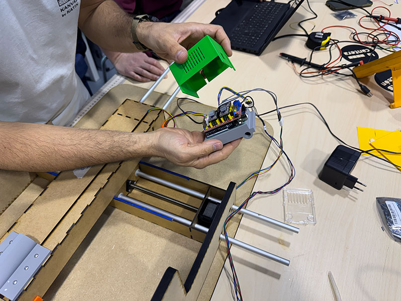
- 3D Electronic CASE -cover- (machine_electronics_cover.stl) STL· 161 Kb
- 3D Electronic CASE -cover- (machine_electronics_cover.f3d) F3D· 108 Kb
- 2D machine case (maquina-caja-v4.3dm) 3DM · 1.1 Mb
- 2D machine case (maquina-caja-v4.svg) SVG · 5 Kb
- 3D .stl & .FCStd files - Support bearings parts (support_bearing.zip) ZIP · 182 Kb
- 3D Z AXIS stepper holder (Zstepper_holder.stl) STL · 180 Kb
- 3D Blade holder (Blade_holder.stl) STL · 180 Kb
- 3D Electronic CASE -holder- (Electronic-holder.stl) STL · 124 Kb
- 3D Electronic CASE -holder- (Electronic-holder.f3z) 3FZ · 124 Kb
Milan OpenDot 2015
León 2020
León 2025
León 2026
Additional Materials
Materials list
| Material | Details |
|---|---|
| M3 Screws (20 mm) | 18 units with washers and nuts |
| M3 Screws (40 mm) | 8 units with washers and nuts |
| Threaded Rod (8 mm) | With 8 nuts and 6 washers |
| Shaft Coupler | 5 mm (NEMA17) to 8 mm |
| Ball Bearings (SKF 608-2RSH/C3) | 3 units – 8 mm inner diameter, 22 mm outer diameter, 7 mm thickness |
| Additional Materials | Remaining components provided by Fab Lab León |