Networking and Communications
Task:-
Group assignment:
Send a message between two projects.
Individual assignments:
design, build and connect wired or wireless node(s) with network or bus addresses and a local input and/or output device(s).
Instructor for this week: Ashish and Saheen.
Individual Assisgnment Overview
For this assignment, I designed a simple communication system between two XIAO RP2040 boards using the I2C protocol. In the first test, I established communication between the master board and one student board. The master board (Sitar PCB) sends commands to the Student 1 audio board through I2C. The Student 1 PCB did not have a JST connector or dedicated I2C connection, so i designed a small breakout board making I2C communication( SDA , SCL).
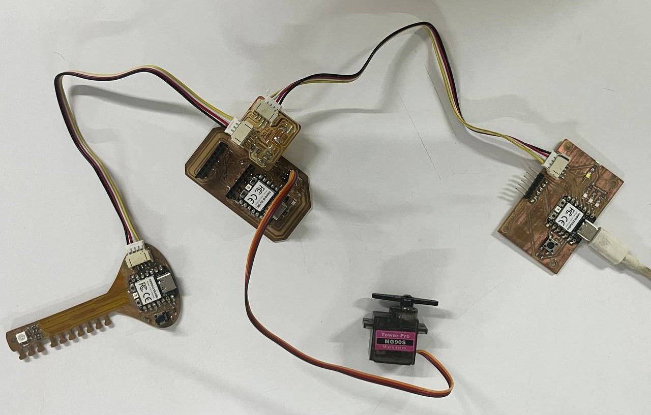
In the second test, I expanded the setup to communicate with two student boards (two nodes). The master board uses different I2C addresses to identify each board and send commands to the selected one. Student 1 controls the servo motor, while Student 2 controls multiple LEDs. The master board uses its push button to select the active board and send commands, while the NeoPixel indicates which board is currently selected and the selected board's led turns on to indicates it has been selected.
I2C Communication
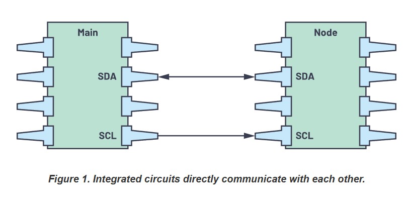
source: I2C-communication-protocol-understanding
12C Communication with the master and a single Node
Master Board:
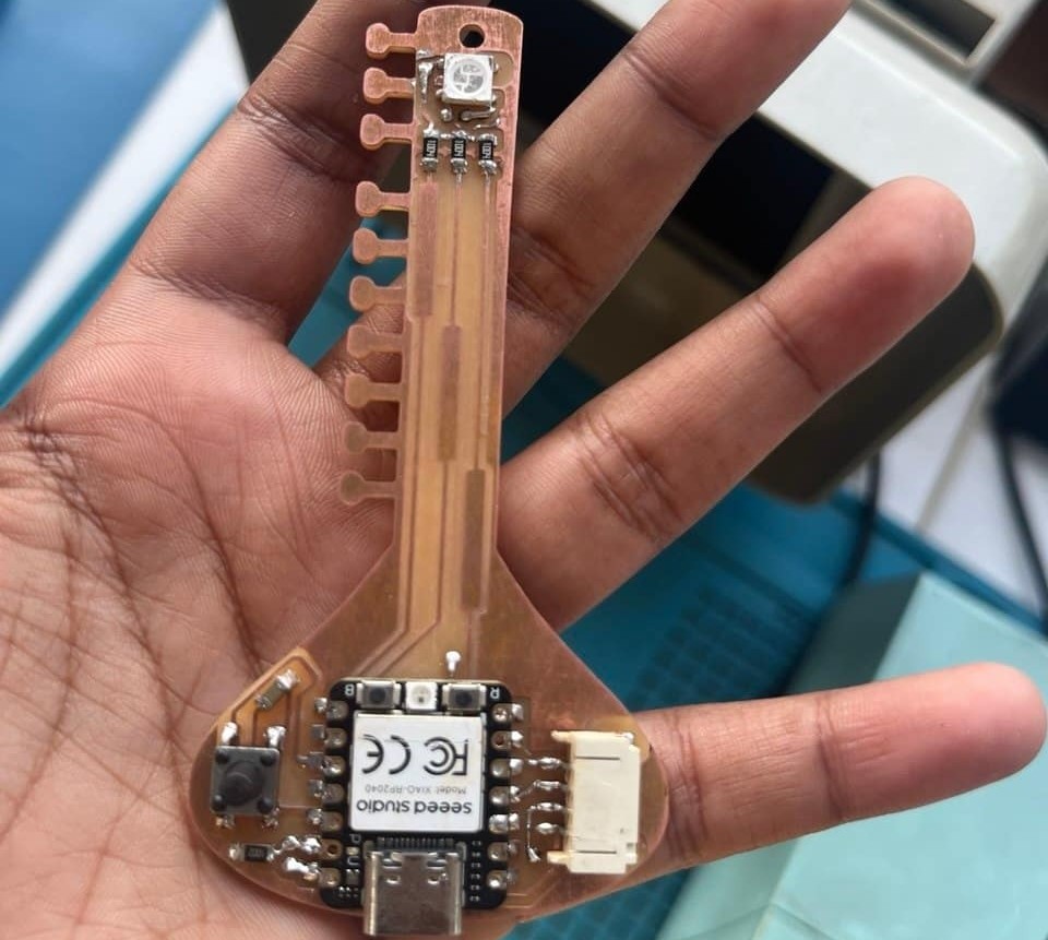
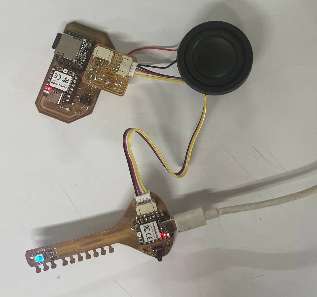
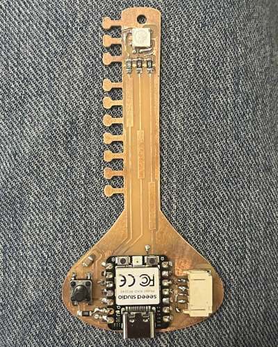
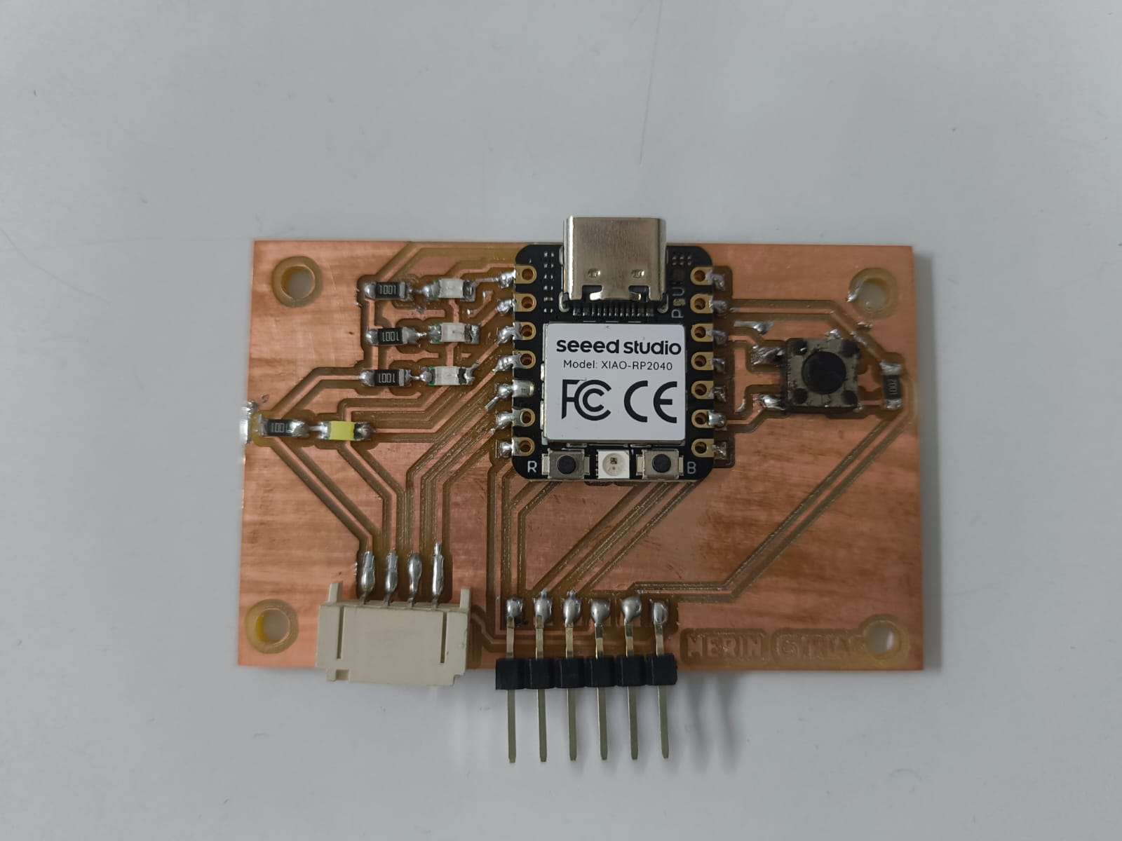
The sitar PCB (input board), which includes a XIAO RP2040, capacitive touch pads, a NeoPixel, a switch, and a JST connector for I2C communication. This board is responisble for sending data to student1 when the pushbutton pressed.
Student1 Board:
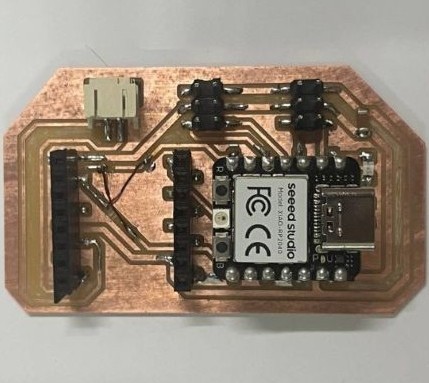
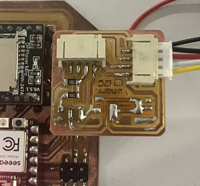
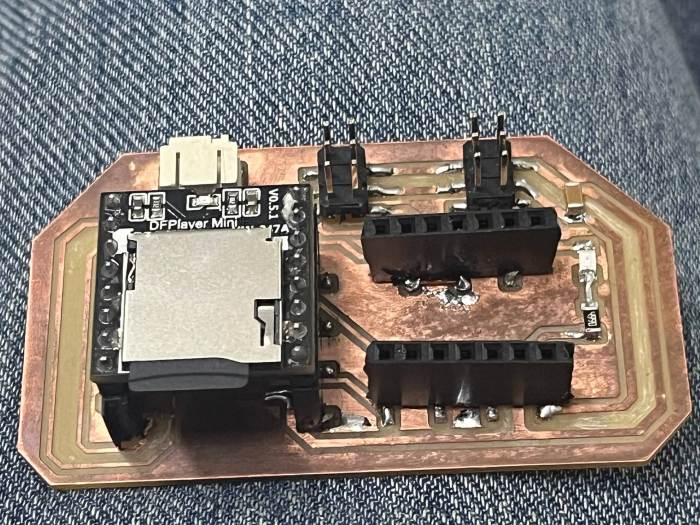
The output device week PCB (audio board), which includes a XIAO RP2040, a DFPlayer Mini MP3 module, and a speaker. This board is responsible for receiving data and playing audio.
The main issue is that the output PCB does not have a JST connector or proper I2C connection points, as it has 4 pin header made for servo motor - used two of them to connect a breakout board.
To solve this, I will design a small breakout board that connects to the servo header using sockets and provides a JST connector with SDA, SCL, VCC, and GND for I2C communication.
The communication flow is as follows:
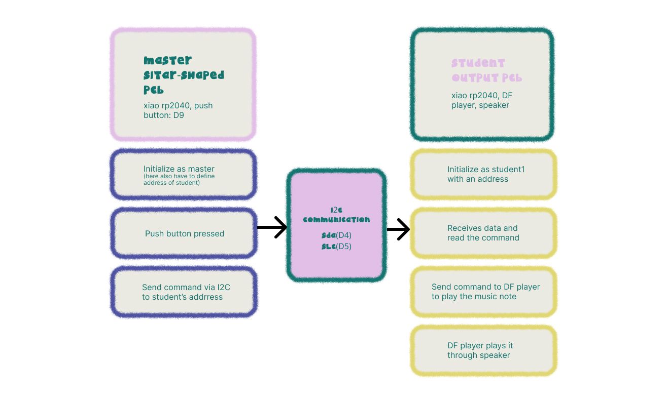
When the pushbutton on the sitar PCB is pressed, the signal is sent via I2C to the output PCB. The output PCB receives this data and triggers the DFPlayer to play the music node through the speaker.
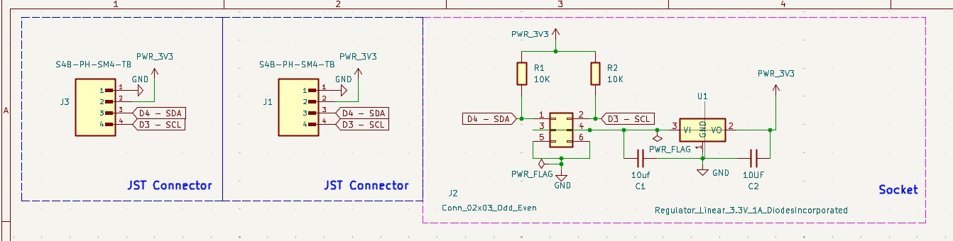
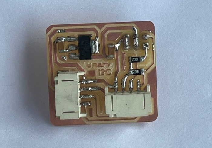
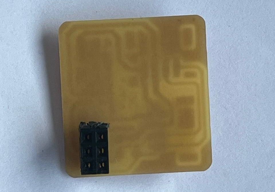
Breakout Board Design
The breakout board includes a 2x3 socket that connects to the output board's header, connects to the SDA: D4, SCL: D5, VCC, and GND pins of xiao rp2040. It also has two JST connectors for I2C communication, allowing the board to connect with two other nodes.
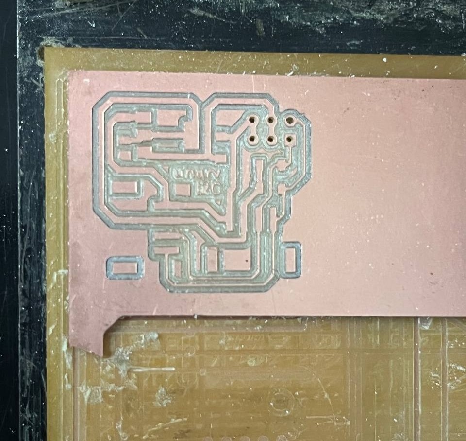
Schematics
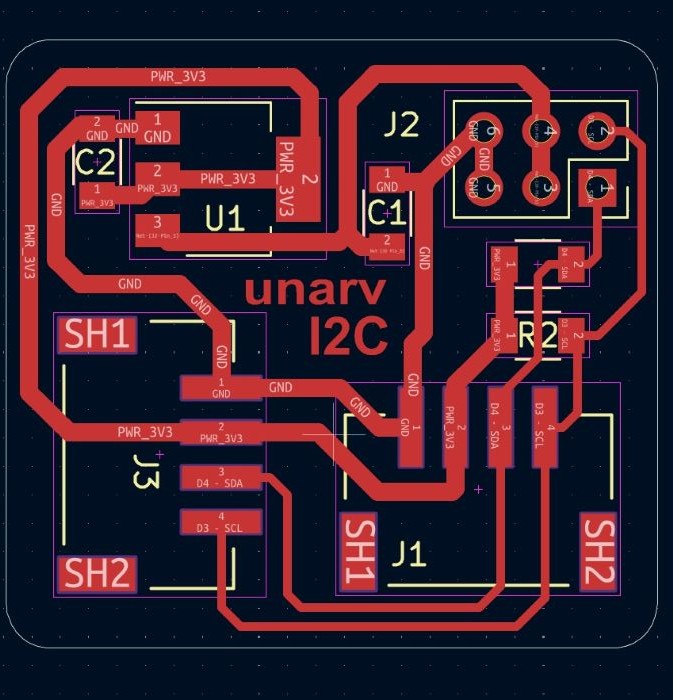
PCB routing
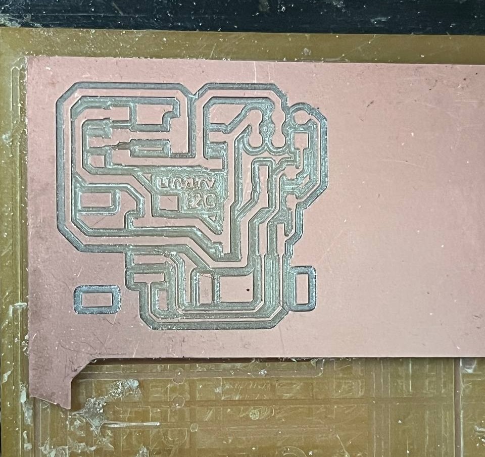
Milling and soldering
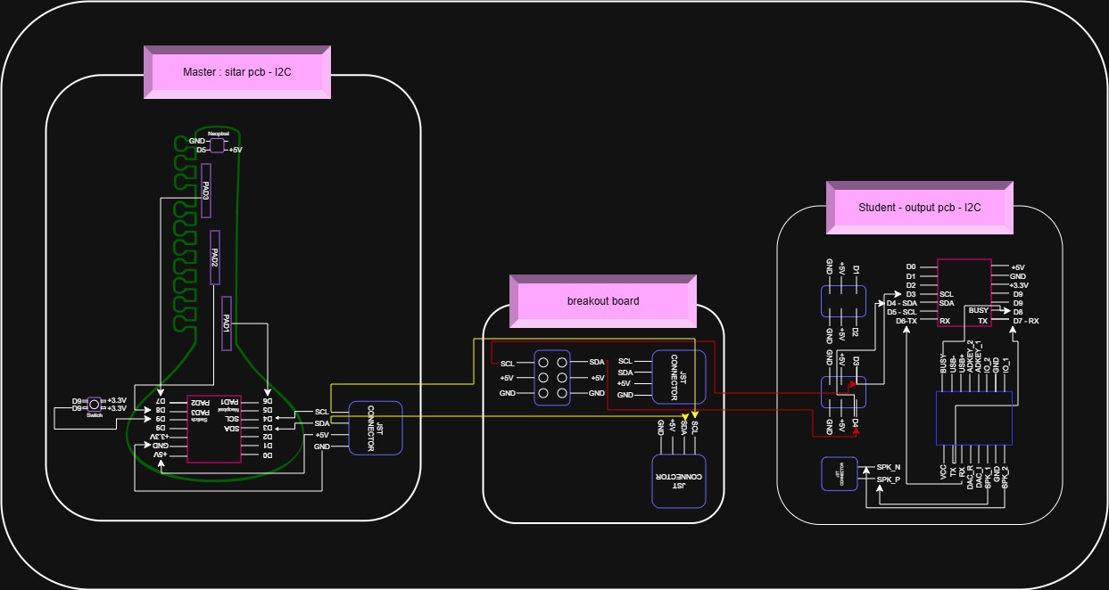
I2C Communication master and peripheral connection drawing
Using the draw.io sketch the communication connection diagram. Draw.io can be used to create diagrams, flowchart for visualization.
This process helps to understand the connections error i made, and understand I2C communication wiring.
From my experience, i recommend to always sketch the connection diagram of nodes before pcb production, to avoid silly mistakes and for better visualization of the communication flow.

I added a voltage regulator assuming the sitar PCB I2C operates at 3.3V,
while the output PCB provides 5V, so instructor suggested add regulation, it the volatges are not matched.
However, later realized that the sitar PCB I2C is already operating at 5V, so the regulator was unnecessary.
Learnings :
First verify the actual operating voltage of all connected boards before adding a voltage regulator
and also understood that in I2C communication, both devices must share the same logic voltage level(for SDA and SCL).
Desoldered the voltage regulator and its capacitor.
After removing them, I shorted the input and output power pads of the voltage regulator footprint on the PCB.
The power path may break, and it is sometimes necessary to short (bridge: means solder both in and out pwr traces) the input and output pads to restore the connection.
In Master Pcb:
In the XIAO RP2040, the KiCad schematic and footprint use physical pin numbering (starting from 1),
while the actual usable pins are labeled as D0, D1, D2… in the pinout.
So the math doesn't process well with me, and connection i made mismatched this mapping. For example:
- Physical pin 4 ≠ D4
- It's actually D3 pin
- Pin 4 as SDA
- Pin 5 as SCL
But in reality, those were D3 and D4, So my I2C connection was wired incorrectly.
SDA: D4, SCL: D5
To make the I2C communication work, I removed the earlier PCB traces and rerouted the SDA and SCL lines correctly using copper wire. I soldered these copper wires onto the Sitar PCB to connect the correct I2C pins.
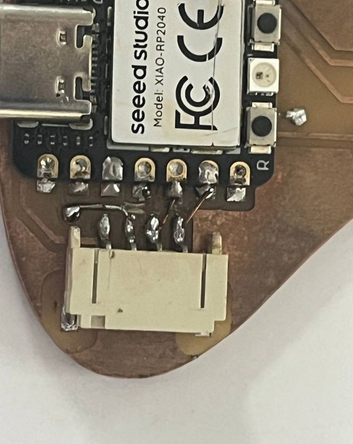
On the output PCB, I shorted SCL (D5) to D3 so that the I2C signal could be accessed through the existing pin header. This allowed the breakout board to plug into the pin header and provide the required SDA, SCL, VCC, and GND connections for I2C communication.
Testing and Programming
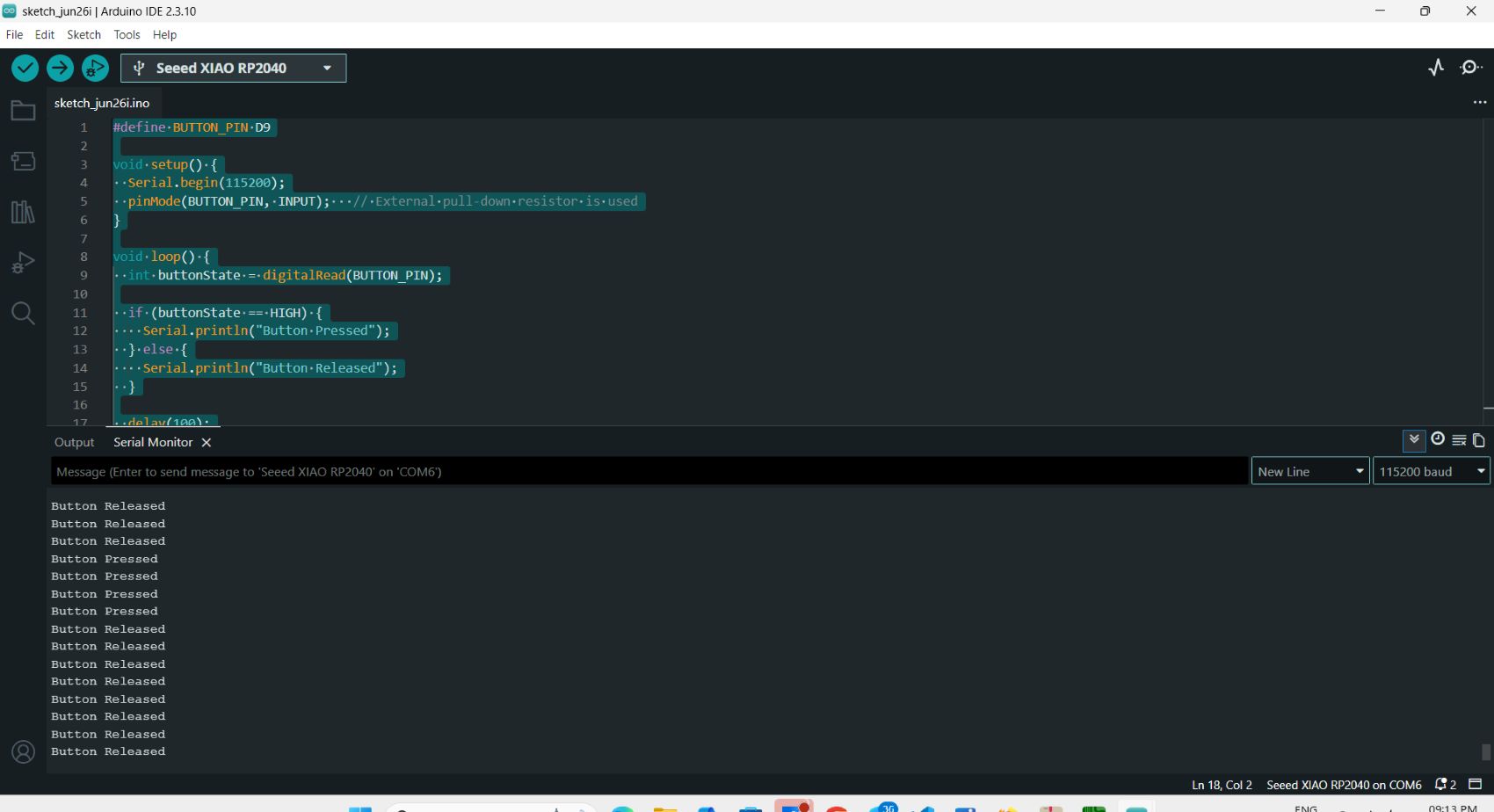
Testing the button
Chatgpt_AI Prompt Used
write code to test A push button is connected to D9 on xiao rp2040 pull_down resistor already there
Button on Master board
              #define BUTTON_PIN D9

              void setup() {
                Serial.begin(115200);
                pinMode(BUTTON_PIN, INPUT);
              }

              void loop() {
                int buttonState = digitalRead(BUTTON_PIN);

                if (buttonState == HIGH) {
                  Serial.println("Button Pressed");
                } else {
                  Serial.println("Button Released");
                }

                delay(100);
              }
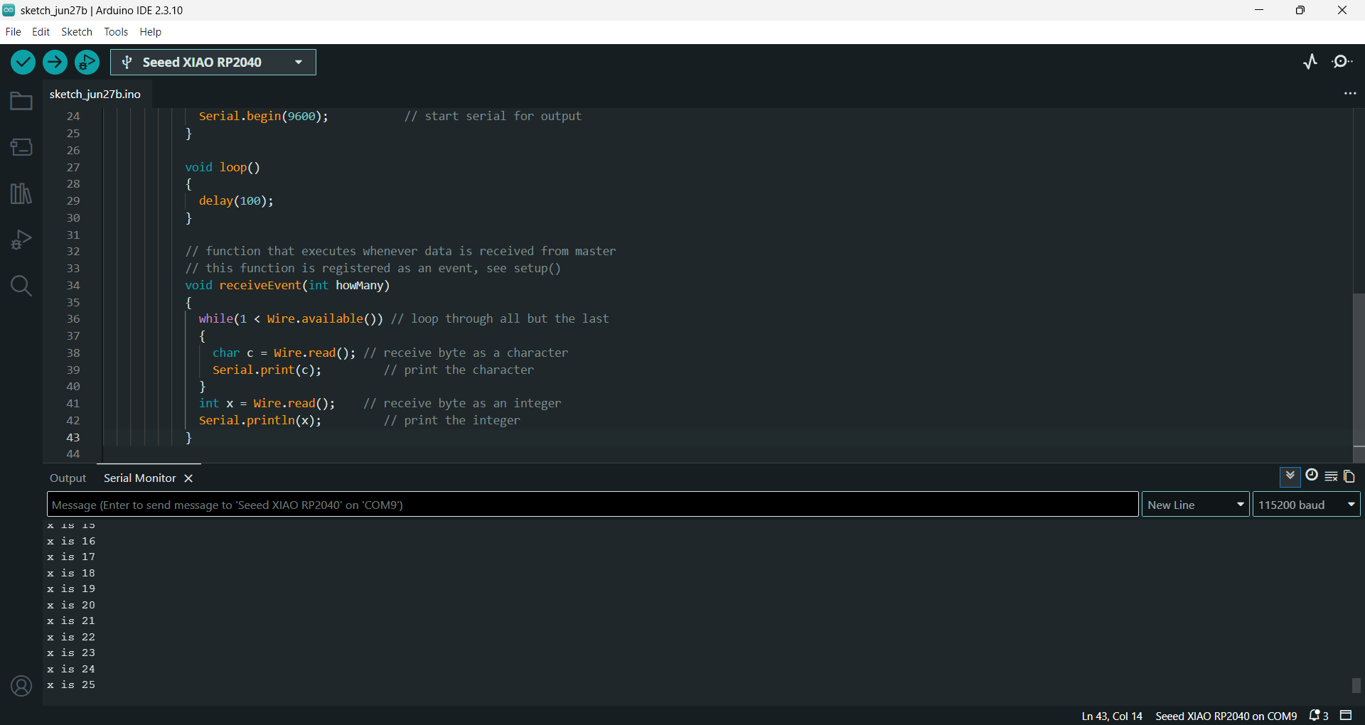
Communication Protocol Test
This code i tool from PaulStoffregen/Wire github which is a basic I2C communication test provided in the Arduino Wire library examples. Its purpose is to verify that two microcontroller boards can communicate successfully over the I2C bus. I used it to test my two board's I2C communication. Expected Result If the wiring is correct:
- The master board repeatedly sends messages every 500 ms.
- The peripheral board receives the messages and displays them on its Serial Monitor.
Master Code
             // Wire Master Writer
            // by Nicholas Zambetti [http://www.zambetti.com](http://www.zambetti.com)

            // Demonstrates use of the Wire library
            // Writes data to an I2C/TWI Peripheral device
            // Refer to the "Wire Peripheral Receiver" example for use with this

            // Created 29 March 2006

            // This example code is in the public domain.


            #include <Wire.h>
            #define SDA_PIN D4
            #define SCL_PIN D5

            void setup() {
              Serial.begin(115200);   // better speed for RP2040
              delay(1000);

              Wire.setSDA(SDA_PIN);   // set SDA pin
              Wire.setSCL(SCL_PIN);   // set SCL pin
              Wire.begin(); // join i2c bus (address optional for master)
            }

            byte x = 0;

            void loop()
            {
              Wire.beginTransmission(4); // transmit to device #4
              Wire.write("x is ");        // sends five bytes
              Wire.write(x);              // sends one byte
              Wire.endTransmission();    // stop transmitting

              x++;
              delay(500);
            }
Peripheral Code
             // Wire Peripheral Receiver
            // by Nicholas Zambetti [http://www.zambetti.com](http://www.zambetti.com)

            // Demonstrates use of the Wire library
            // Receives data as an I2C/TWI Peripheral device
            // Refer to the "Wire Master Writer" example for use with this

            // Created 29 March 2006

            // This example code is in the public domain.

            #include <Wire.h>
            #define SDA_PIN D4
            #define SCL_PIN D5

            void setup() {
              Serial.begin(115200);   // better speed for RP2040
              delay(1000);

              Wire.setSDA(SDA_PIN);   // set SDA pin
              Wire.setSCL(SCL_PIN);   // set SCL pin
              Wire.begin(4);                // join i2c bus with address #4
              Wire.onReceive(receiveEvent); // register event
              Serial.begin(9600);           // start serial for output
            }

            void loop()
            {
              delay(100);
            }

            // function that executes whenever data is received from master
            // this function is registered as an event, see setup()
            void receiveEvent(int howMany)
            {
              while(1 < Wire.available()) // loop through all but the last
              {
                char c = Wire.read(); // receive byte as a character
                Serial.print(c);         // print the character
              }
              int x = Wire.read();    // receive byte as an integer
              Serial.println(x);         // print the integer
            }
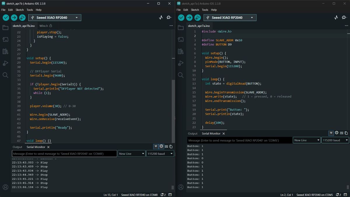
I2C Communication: Play Audio While Button is Pressed
Chatgpt_AI Prompt Used
I designed an output PCB(student) using the Seeed Studio XIAO RP2040, which includes an LED connected to pin D0 through a 499ohm resistor and a 10uF capacitor, DFPlayer Mini module -
with the speaker connected to SPK1 and SPK2, and the BUSY pin connected to D8, Module's TX to xiao's RX, Modules RX to xiao's TX.
To enable communication between boards, I designed a breakout board using a vertical 2x3 pin socket
and 2 JST S4B-PH connectors. This breakout board connects the output PCB and the sitar PCB.
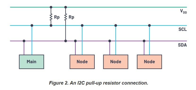
The I2C lines include 10kohm pull-up resistors to ensure stable communication.
On the sitar PCB (master), the JST connector intended for I2C communication
is wired to default configuration of the XIAO RP2040 (SDA >> D4, SCL >> D5).
The sitar PCB includes capacitive touch pads: PAD1 connected to D6, PAD2 to D8,
and PAD3 to D7, each with 1Mohm resistors.
A push button is connected to D9 with a 10kohm resistor, and a NeoPixel LED is connected to D5.
Give program to play music while the button is pressed; button is on sitar pcb, mp3 module in output pcb - in SD card, folder is made in name: 01 and play 0001.mp3 inside that folder.
I2C Addressing and Communication
Student1 Addressing
#define STUDENT_ADDR 0x10 // I2C address of the student board
The same addresses are also defined in the Master board codes.
Master Communication Controls
#include <Wire.h> // Include the I2C communication library
Wire.begin(); //Initialize this board as the I2C master
              Wire.beginTransmission(SLAVE_ADDR); //Start sending data to Student 1
              Wire.write(state);   // 1 = pressed, 0 = released
              Wire.endTransmission(); // end 12C transmision
The master board transmits the button state (1 for pressed and 0 for released) to Student 1 (0x10 ) using its address. Student 1 interprets this data to play or stop the audio.
Master Code
            #include  // I2C communication library

            #define STUDENT_ADDR 0x10 // I2C address of the student board
            #define BUTTON D9

            void setup() {
              Wire.begin(); //Initialize this board as the I2C master
              pinMode(BUTTON, INPUT);
              Serial.begin(115200);
            }

            void loop() {
              int state = digitalRead(BUTTON); // read current button state

              Wire.beginTransmission(SLAVE_ADDR); //Start sending data to Student 1
              Wire.write(state);   // 1 = pressed, 0 = released
              Wire.endTransmission(); // end 12C transmision

              Serial.print("Button: ");
              Serial.println(state); // Print the button state

              delay(100);
            }
Peripheral Code
            #include <Wire.h>  // I2C communication library
            #include <DFRobotDFPlayerMini.h>  // DFPlayer Mini library

            #define STUDENT_ADDR 0x10 // I2C address of Student 1

            DFRobotDFPlayerMini player;
           // Create a DFPlayer Mini object to control audio playback
            bool isPlaying = false;  // Keeps track of whether audio is playing

            void receiveEvent(int howMany) {
              // this function is called whenever data is received from the master
              while (Wire.available()) {
                int val = Wire.read();  // Read the received value (0 or 1)

                if (val == 1 && !isPlaying) {
                    // If master sends 1 means button pressed and audio is not already playing
                  Serial.println("Play");
                  player.playFolder(1, 1);  // plays 0001.mp3 in folder 01
                  isPlaying = true;
                }

                if (val == 0 && isPlaying) {
                    // If master sends 0 and audio is playing
                  Serial.println("Stop");
                  player.stop(); // Stop audio playback
                  isPlaying = false;
                }
              }
            }

            void setup() {
              Serial.begin(115200);

              // DFPlayer Serial
              Serial1.begin(9600);

              if (!player.begin(Serial1)) {
                Serial.println("DFPlayer NOT detected");
                while (1);
              }

              player.volume(0); // 0-30

              Wire.begin(SLAVE_ADDR); // Initialize as I2C slave with address 0x10
              Wire.onReceive(receiveEvent); // receive function

              Serial.println("Ready");
            }

            void loop() {}
12C Communication with the master and two Node
Master Board:
The sitar PCB (input board)
which includes a XIAO RP2040, capacitive touch pads, a NeoPixel, a switch, and a JST connector for I2C communication.
This board acts as the master and uses different I2C addresses to communicate with two student boards.
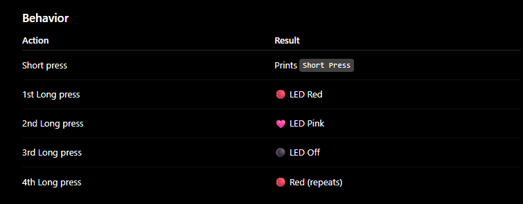
The first long press on the push button selects Student 1, and the onboard NeoPixel changes to pink.
The next long press selects Student 2, and the NeoPixel changes to red.
After a board is selected, each short press sends commands only to the selected board.
Student1 Board:
The output device week PCB which includes a XIAO RP2040, a servo motor, and a status LED. This board is responsible for receiving data from the master. When selected, the status LED turns ON, and each short press from the master toggles the servo motor between 90° and 180°
Student2 Board:
source: Merin
For Student2, I used Merin's custom PCB, which was designed and fabricated during the Electronics Design Week.
In Merin's custom PCB has a XIAO RP2040 and four LEDs.
This board is also connected to the same I2C bus but uses a different I2C address.
When selected, LED4 turns ON to indicate the active board. Each short press from the master then turns on LED3, LED2, and LED1 sequentially.
The communication flow is as follows:
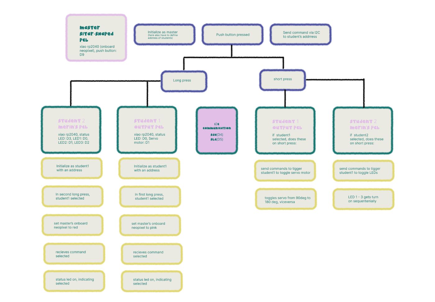
- On the first long press, the master selects Student 1 and changes the onboard NeoPixel to pink.
- A short press sends an I2C command to Student 1, which toggles the servo motor between 90° and 180°.
- On the next long press, the master selects Student 2 and changes the onboard NeoPixel to red.
- A short press then sends an I2C command to Student 2, where LED4 remains ON to indicate the selected board and LED3, LED2, and LED1 turn ON sequentially with each button press.
Testing and Programming
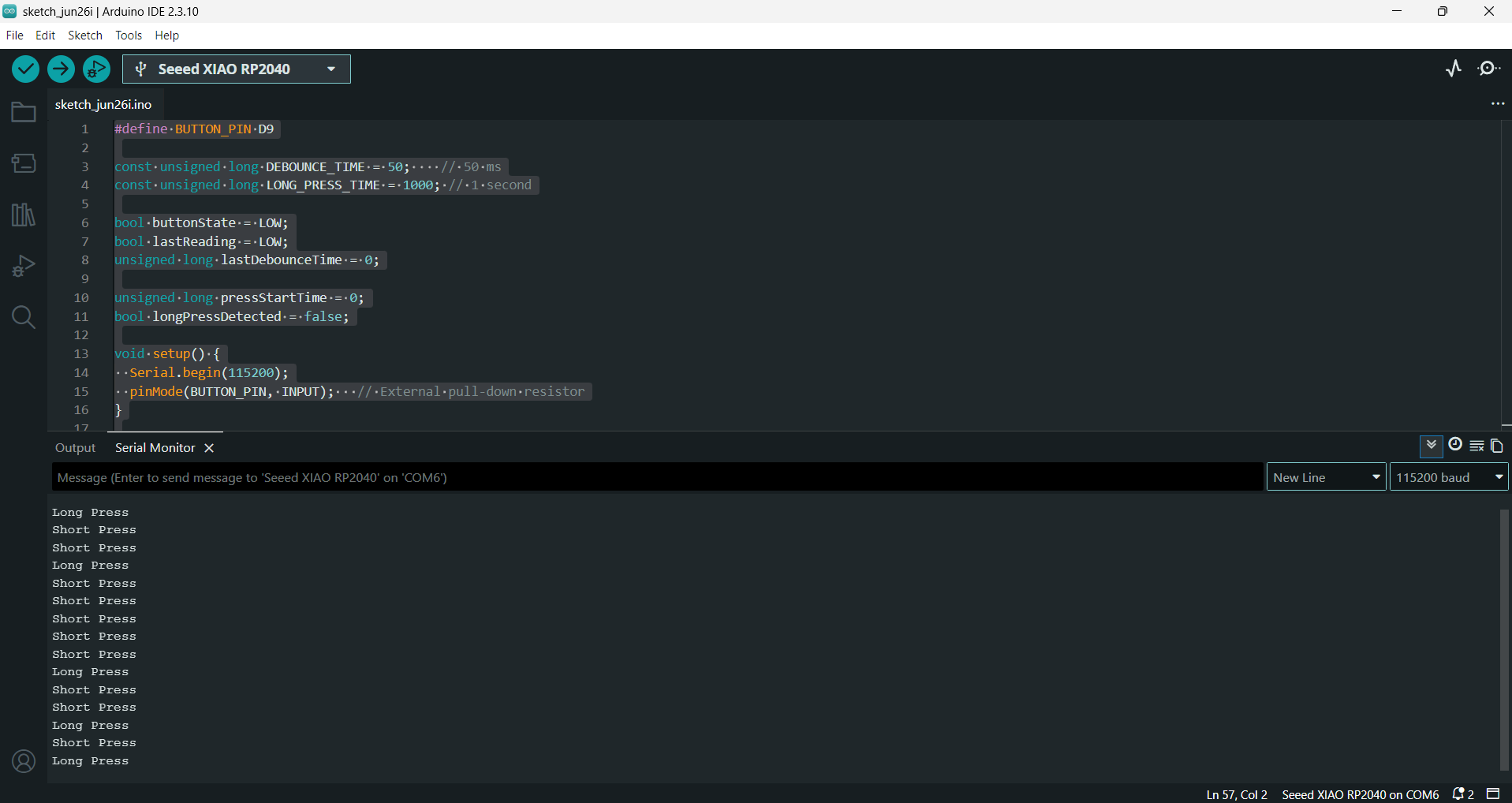
Testing if it detect long press and short press of button
Chatgpt_AI Prompt Used
write code to test A push button is connected to D9 on xiao rp2040 pull_down resistor already there
then it gave a code to indicates when button pressed and it worked. For getting Testing if it detect long press and short press of button code, i prompted:
test successfull now add long and short press functionality to this code
Button on Master board
             #define BUTTON_PIN D9

            const unsigned long DEBOUNCE_TIME = 50;    // 50 ms
            const unsigned long LONG_PRESS_TIME = 1000; // 1 second

            bool buttonState = LOW;
            bool lastReading = LOW;
            unsigned long lastDebounceTime = 0;

            unsigned long pressStartTime = 0;
            bool longPressDetected = false;

            void setup() {
              Serial.begin(115200);
              pinMode(BUTTON_PIN, INPUT);   // External pull-down resistor
            }

            void loop() {
              bool reading = digitalRead(BUTTON_PIN);

              // Check if the input changed
              if (reading != lastReading) {
                lastDebounceTime = millis();
              }

              // If the reading has been stable long enough
              if ((millis() - lastDebounceTime) > DEBOUNCE_TIME) {

                if (reading != buttonState) {
                  buttonState = reading;

                  // Button pressed
                  if (buttonState == HIGH) {
                    pressStartTime = millis();
                    longPressDetected = false;
                  }

                  // Button released
                  else {
                    if (!longPressDetected) {
                      Serial.println("Short Press");
                    }
                  }
                }

                // Check for long press
                if (buttonState == HIGH &&
                    !longPressDetected &&
                    (millis() - pressStartTime >= LONG_PRESS_TIME)) {

                  Serial.println("Long Press");
                  longPressDetected = true;
                }
              }

              lastReading = reading;
            }
Testing onboard neopixel of Xiao rp2040 on Master Board
Chatgpt_AI Prompt Used
neopixel is not working, for your reference here is the code from seed wiki (then i pasted the code from onboard neopixel code of xiao rp2040)
source: Seeed_WIKI
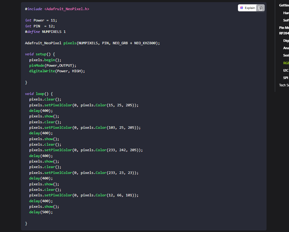
Onboard Neopixel of Xiao rp2040 on Master board
              #include <Adafruit_NeoPixel.h> // Include the NeoPixel library

              #define LED_POWER 11  // Power control pin for the onboard NeoPixel
              #define LED_PIN 12   // Data pin connected to the NeoPixel
              #define NUMPIXELS 1 // Number of NeoPixels

              // Create a NeoPixel object
              Adafruit_NeoPixel pixel(NUMPIXELS, LED_PIN, NEO_GRB + NEO_KHZ800);

              void setup() {

                pinMode(LED_POWER, OUTPUT);  // Set the power pin as an output
                digitalWrite(LED_POWER, HIGH);  // Turn on power to the NeoPixel

                pixel.begin(); // Initialize the NeoPixel
              }

              void loop() {

                pixel.setPixelColor(0, pixel.Color(255,0,0)); // Set the LED to red
                pixel.show();  // Update the NeoPixel
                delay(1000);  // Wait for 1 second

                pixel.setPixelColor(0, pixel.Color(255,20,147)); // Set the LED to pink
                pixel.show();   // Update the NeoPixel
                delay(1000);   // Wait for 1 second

                pixel.clear();  // Turn off the NeoPixel
                pixel.show();  // Update the NeoPixel
                delay(1000);  // Wait for 1 second
              }
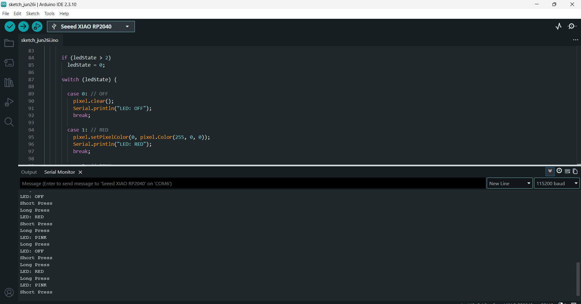
Testing button press and onboard neopixel of Xiao rp2040 on Master Board
Chatgpt_AI Prompt Used
yes it is working. now combine the code all together
As the "testing if it detect long press and short press of button code" and "Testing onboard neopixel of Xiao rp2040 on Master Board code" worked so asked to combine both together.
             #include <Adafruit_NeoPixel.h>   // Include the NeoPixel library

              #define BUTTON_PIN D9              // Push button pin

              // Built-in NeoPixel (XIAO RP2040)
              #define LED_POWER 11               // Power pin for the onboard NeoPixel
              #define LED_PIN 12                 // Data pin for the NeoPixel
              #define NUMPIXELS 1                // Number of NeoPixels

              // Create a NeoPixel object
              Adafruit_NeoPixel pixel(NUMPIXELS, LED_PIN, NEO_GRB + NEO_KHZ800);

              // Timing constants
              const unsigned long DEBOUNCE_TIME = 50;      // Debounce delay (ms)
              const unsigned long LONG_PRESS_TIME = 1000;  // Long press duration (ms)

              // Button variables
              bool buttonState = LOW;             // Current stable button state
              bool lastReading = LOW;             // Previous button reading
              unsigned long lastDebounceTime = 0; // Last debounce time

              unsigned long pressStartTime = 0;   // Time when button was pressed
              bool longPressDetected = false;     // Tracks whether a long press occurred

              // LED state
              int ledState = 0;   // 0 = OFF, 1 = RED, 2 = PINK

              void setup() {

                Serial.begin(115200);             // Start serial communication

                pinMode(BUTTON_PIN, INPUT);       // Configure button pin as input

                // Enable power to the onboard NeoPixel
                pinMode(LED_POWER, OUTPUT);
                digitalWrite(LED_POWER, HIGH);

                // Initialize the NeoPixel
                pixel.begin();
                pixel.clear();                    // Turn off the LED
                pixel.show();

                Serial.println("Ready");
              }

              void loop() {

                // Read the button state
                bool reading = digitalRead(BUTTON_PIN);

                // Debounce the button
                if (reading != lastReading) {
                  lastDebounceTime = millis();
                }

                if ((millis() - lastDebounceTime) > DEBOUNCE_TIME) {

                  // Detect button state change
                  if (reading != buttonState) {
                    buttonState = reading;

                    if (buttonState == HIGH) {
                      // Button has been pressed
                      pressStartTime = millis();
                      longPressDetected = false;
                    }
                    else {
                      // Button has been released
                      if (!longPressDetected) {
                        Serial.println("Short Press");
                        // Add short press action here if needed
                      }
                    }
                  }

                  // Detect a long press
                  if (buttonState == HIGH &&
                      !longPressDetected &&
                      (millis() - pressStartTime >= LONG_PRESS_TIME)) {

                    longPressDetected = true;
                    Serial.println("Long Press");

                    // Cycle through LED states
                    ledState++;

                    if (ledState > 2)
                      ledState = 0;

                    switch (ledState) {

                      case 0: // Turn LED OFF
                        pixel.clear();
                        Serial.println("LED: OFF");
                        break;

                      case 1: // Set LED to RED
                        pixel.setPixelColor(0, pixel.Color(255, 0, 0));
                        Serial.println("LED: RED");
                        break;

                      case 2: // Set LED to PINK
                        pixel.setPixelColor(0, pixel.Color(255, 20, 147));
                        Serial.println("LED: PINK");
                        break;
                    }

                    pixel.show();                 // Update the NeoPixel
                  }
                }

                // Save the current reading for the next loop
                lastReading = reading;
              }
12C Communication:Master and 2 Nodes
Chatgpt_AI Prompt Used
            I designed an output PCB(student1) using the Seeed Studio XIAO RP2040, which includes an LED connected to pin D0 through a 499ohm resistor and a 10uF capacitor, servo motor d1 .


             Merin board(student2) has Seeed Studio XIAO RP2040 led1 connected to d0 , led 2 connected to d1, led3 connected to d2, led4 connected to d3.


              To enable communication between boards, I designed a breakout board using a vertical 2x3 pin socket and 2 JST S4B-PH connectors.
              This breakout board connects the output PCB and the sitar PCB.
              The I2C lines include 10kohm pull-up resistors to ensure stable communication.
              On the sitar PCB (master), the JST connector intended for I2C communication is wired to default configuration of the XIAO RP2040 (SDA >> D4, SCL >> D5).


               The sitar PCB includes capacitive  A push button is connected to D9 with a 10kohm resistor.


               Give program for when the master board's push button first long press selects student 1 for
               indicating it has been selected on master's xiao onboard neopixel changes color to pink and student1 led on.
                Next press on the master's push button works the servo motor (90,180 deg) on student1. Second long press on master's
                push button selects student2 for indicating has been selected master's xiao onboard neopixel change color to red, and turn on student2 led4 on d5 .
                 on normal presses it will on led3, next press led2, next press led1 give code and address like student1, student2 also the adrdress defining
                 in the master should be same definig in the students code 12c communication.
                  Also give feedbacks of every action happening in serial monitor
Later for master again prompted
As the code first given is not detecting the long press and short press. Prompted again by "giving Testing button press and onboard neopixel of Xiao rp2040 on Master Board code"
and asked to refer this given code and the long press should be selecting the student boards , short press for sending
controlling the ouputs in the student's board. combine this with master code.
I2C Addressing and Communication
Each student board is given its own I2C address so that the master knows which board to communicate with.
Node Addressing
              #define STUDENT1_ADDR 0x10 // Student 1 address
              #define STUDENT2_ADDR 0x20 // Student 2 address
The same addresses are also defined in the corresponding student board codes. This helps the master send data to the selected board.
Master Communication Controls
The master controls which node receives the data. As it initializes the I2C bus using:
#include <Wire.h> // Include the I2C communication library
Wire.begin();
Whenever the master needs to send a command, it uses the sendCommand() function. This function takes the node address and the command, then sends the data through the I2C bus.
              void sendCommand(byte addr, char cmd)
            {
              Wire.beginTransmission(addr);
              Wire.write(cmd);
              Wire.endTransmission();
            }
The first long press selects Student1 (0x10), and the next long press selects Student2 (0x20). Once a node is selected, every short press sends commands only to the selected node using its I2C address.
Master Code
#include <Wire.h>
#include <Adafruit_NeoPixel.h>
#define BUTTON_PIN D9
// XIAO RP2040 Built-in NeoPixel
#define LED_POWER 11
#define LED_PIN 12
#define NUMPIXELS 1
#define STUDENT1_ADDR 0x10 // student1 address
#define STUDENT2_ADDR 0x20 // student2 address
Adafruit_NeoPixel pixel(NUMPIXELS, LED_PIN, NEO_GRB + NEO_KHZ800);
// ---------------- Button ----------------
const unsigned long DEBOUNCE_TIME = 50;
const unsigned long LONG_PRESS_TIME = 1000;
bool buttonState = LOW;
bool lastReading = LOW;
unsigned long lastDebounceTime = 0;
unsigned long pressStartTime = 0;
bool longPressDetected = false;
// ---------------- Selection ----------------
int selectedStudent = 0; // 1 = Student1, 2 = Student2
int student2Step = 0;
// ------------------------------------------------
void sendCommand(byte addr, char cmd)
{
Wire.beginTransmission(addr);
Wire.write(cmd);
Wire.endTransmission();
}
void selectStudent1()
{
selectedStudent = 1;
pixel.clear();
pixel.setPixelColor(0, pixel.Color(255,20,147));
pixel.show();
sendCommand(STUDENT2_ADDR,'X');
delay(10);
sendCommand(STUDENT1_ADDR,'S');
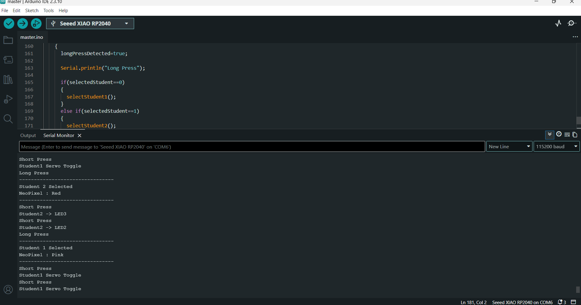
Serial.println("--------------------------------");
Serial.println("Student 1 Selected");
Serial.println("NeoPixel : Pink");
Serial.println("--------------------------------");
}
void selectStudent2()
{
selectedStudent = 2;
pixel.clear();
pixel.setPixelColor(0, pixel.Color(255,0,0));
pixel.show();
sendCommand(STUDENT1_ADDR,'X');
delay(10);
sendCommand(STUDENT2_ADDR,'S');
student2Step=0;
Serial.println("--------------------------------");
Serial.println("Student 2 Selected");
Serial.println("NeoPixel : Red");
Serial.println("--------------------------------");
}
void shortPressAction()
{
if(selectedStudent==1)
{
sendCommand(STUDENT1_ADDR,'O');
Serial.println("Student1 Servo Toggle");
}
else if(selectedStudent==2)
{
student2Step++;
if(student2Step==1)
{
sendCommand(STUDENT2_ADDR,'1');
Serial.println("Student2 -> LED3");
}
else if(student2Step==2)
{
sendCommand(STUDENT2_ADDR,'2');
Serial.println("Student2 -> LED2");
}
else
{
sendCommand(STUDENT2_ADDR,'3');
Serial.println("Student2 -> LED1");
student2Step=0;
}
}
}
void setup()
{
Serial.begin(115200);
pinMode(BUTTON_PIN, INPUT);
Wire.begin();
pinMode(LED_POWER, OUTPUT);
digitalWrite(LED_POWER, HIGH);
pixel.begin();
pixel.clear();
pixel.show();
Serial.println("MASTER READY");
}
void loop()
{
bool reading = digitalRead(BUTTON_PIN);
if(reading != lastReading)
{
lastDebounceTime = millis();
}
if((millis()-lastDebounceTime) > DEBOUNCE_TIME)
{
if(reading != buttonState)
{
buttonState = reading;
if(buttonState == HIGH)
{
pressStartTime = millis();
longPressDetected = false;
}
else
{
if(!longPressDetected)
{
Serial.println("Short Press");
shortPressAction();
}
}
}
if(buttonState == HIGH &&
!longPressDetected &&
millis()-pressStartTime >= LONG_PRESS_TIME)
{
longPressDetected=true;
Serial.println("Long Press");
if(selectedStudent==0)
{
selectStudent1();
}
else if(selectedStudent==1)
{
selectStudent2();
}
else
{
selectStudent1();
}
}
}
lastReading = reading;
}
Student1 Code
              #include <Wire.h>  // Include the I2C communication library
              #include <Servo.h> // Include the Servo library

              #define STUDENT1_ADDR 0x10 // I2C address of Student 1

              #define LED_PIN D0 // LED connected to pin D0
              #define SERVO_PIN D1 // Servo connected to pin D1

              Servo myServo; // Create a Servo object

              bool servoState = false; // Stores the current servo position

              void setup()
              {
                Serial.begin(115200); // Start serial communication

                pinMode(LED_PIN, OUTPUT);  // Configure LED pin as output
                digitalWrite(LED_PIN, LOW);// Turn LED OFF initially

                myServo.attach(SERVO_PIN); // Attach the servo to pin D1
                myServo.write(90);         // Set servo to its initial position (90°)

                Wire.begin(STUDENT1_ADDR); // Initialize as an I²C slave with address 0x10
                Wire.onReceive(receiveEvent); // Register the receive event function

                Serial.print("Student 1 Ready. I2C Address: 0x");
                Serial.println(STUDENT1_ADDR, HEX);
              }

              // Function called whenever data is received from the master
              void receiveEvent(int howMany)
              {
                while (Wire.available())
                {
                  char cmd = Wire.read();  // Read the received command

                  switch (cmd)
                  {
                    case 'S':  // Student 1 selected
                      digitalWrite(LED_PIN, HIGH);   // Turn LED ON
                      Serial.println("Student 1 Selected (LED ON)");
                      break;

                    case 'X':  // Student 1 deselected
                      digitalWrite(LED_PIN, LOW);    // Turn LED OFF
                      Serial.println("Student 1 Deselected (LED OFF)");
                      break;

                    case 'O':  // Toggle the servo position
                      servoState = !servoState;

                      if (servoState)
                      {
                        myServo.write(180); // Rotate servo to 180°
                        Serial.println("Servo -> 180°");
                      }
                      else
                      {
                        myServo.write(90);  // Rotate servo back to 90°
                        Serial.println("Servo -> 90°");
                      }
                      break;

                    default:  // Unknown command received
                      Serial.print("Unknown command: ");
                      Serial.println(cmd);
                      break;
                  }
                }
              }

              void loop()
              {
                // No code required here.
                // The board waits for I²C commands from the master.
              }
Student2 Code
              #include <Wire.h>          // Include the I²C communication library

              #define STUDENT2_ADDR 0x20   // I²C address of Student 2

              #define LED1 D0              // LED1 connected to pin D0
              #define LED2 D1              // LED2 connected to pin D1
              #define LED3 D2              // LED3 connected to pin D2
              #define LED4 D3              // LED4 connected to pin D3

              void setup()
              {
                Serial.begin(115200);      // Start serial communication

                pinMode(LED1, OUTPUT);     // Configure LED1 as output
                pinMode(LED2, OUTPUT);     // Configure LED2 as output
                pinMode(LED3, OUTPUT);     // Configure LED3 as output
                pinMode(LED4, OUTPUT);     // Configure LED4 as output

                offAll();                  // Turn OFF all LEDs initially

                Wire.begin(STUDENT2_ADDR); // Initialize as an I²C slave with address 0x20
                Wire.onReceive(receiveEvent); // Register the receive event function

                Serial.print("Student 2 Ready. I2C Address: 0x");
                Serial.println(STUDENT2_ADDR, HEX);
              }

              // Function to turn OFF all LEDs
              void offAll()
              {
                digitalWrite(LED1, LOW);
                digitalWrite(LED2, LOW);
                digitalWrite(LED3, LOW);
                digitalWrite(LED4, LOW);
              }

              // Function called whenever data is received from the master
              void receiveEvent(int howMany)
              {
                while (Wire.available())
                {
                  char cmd = Wire.read();  // Read the received command

                  switch (cmd)
                  {
                    case 'S':              // Student 2 selected
                      offAll();
                      digitalWrite(LED4, HIGH);      // Turn ON LED4 as selection indicator
                      Serial.println("Student 2 Selected (LED4 ON)");
                      break;

                    case 'X':              // Student 2 deselected
                      offAll();                        // Turn OFF all LEDs
                      Serial.println("Student 2 Deselected (All LEDs OFF)");
                      break;

                    case '1':              // Command to turn ON LED3
                      offAll();
                      digitalWrite(LED4, HIGH);      // Keep LED4 ON to indicate selection
                      digitalWrite(LED3, HIGH);
                      Serial.println("LED3 ON");
                      break;

                    case '2':              // Command to turn ON LED2
                      offAll();
                      digitalWrite(LED4, HIGH);
                      digitalWrite(LED2, HIGH);
                      Serial.println("LED2 ON");
                      break;

                    case '3':              // Command to turn ON LED1
                      offAll();
                      digitalWrite(LED4, HIGH);
                      digitalWrite(LED1, HIGH);
                      Serial.println("LED1 ON");
                      break;

                    default:               // Unknown command received
                      Serial.print("Unknown command: ");
                      Serial.println(cmd);
                      break;
                  }
                }
              }

              void loop()
              {
                // No code required here.
                // The board waits for I²C commands from the master.
              }
Overview of Group Assignment
The main objective of the group assignment was to make two different projects communicate with each other, either through wired or wireless communication. We used Mishael's and Nadec's boards and made them share information with each other. For this two-way communication, we used wireless communication protocols, the boards exchange data over the air.
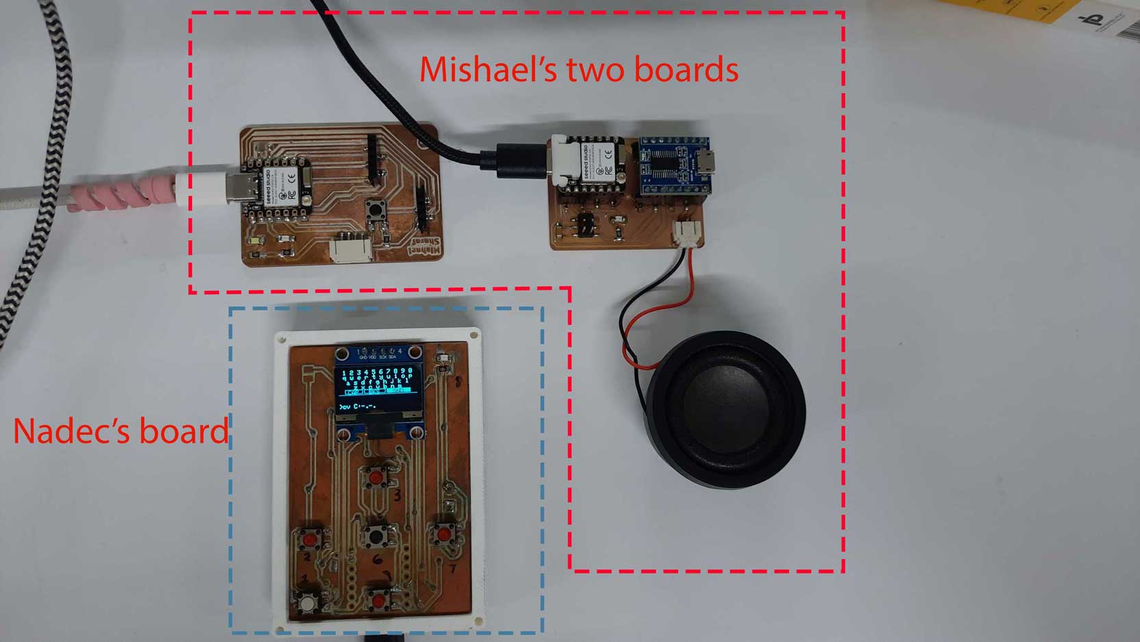
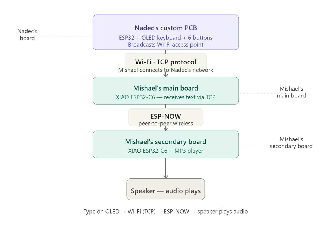
For detailed information, refer to: Week 11 Group Assignment.