My batch said it like a paper fortune teller ("cootie catcher") is a classic origami game. They are playing that game with my flaps.
3D Scanning and Printing
Task:-
Group assignment:
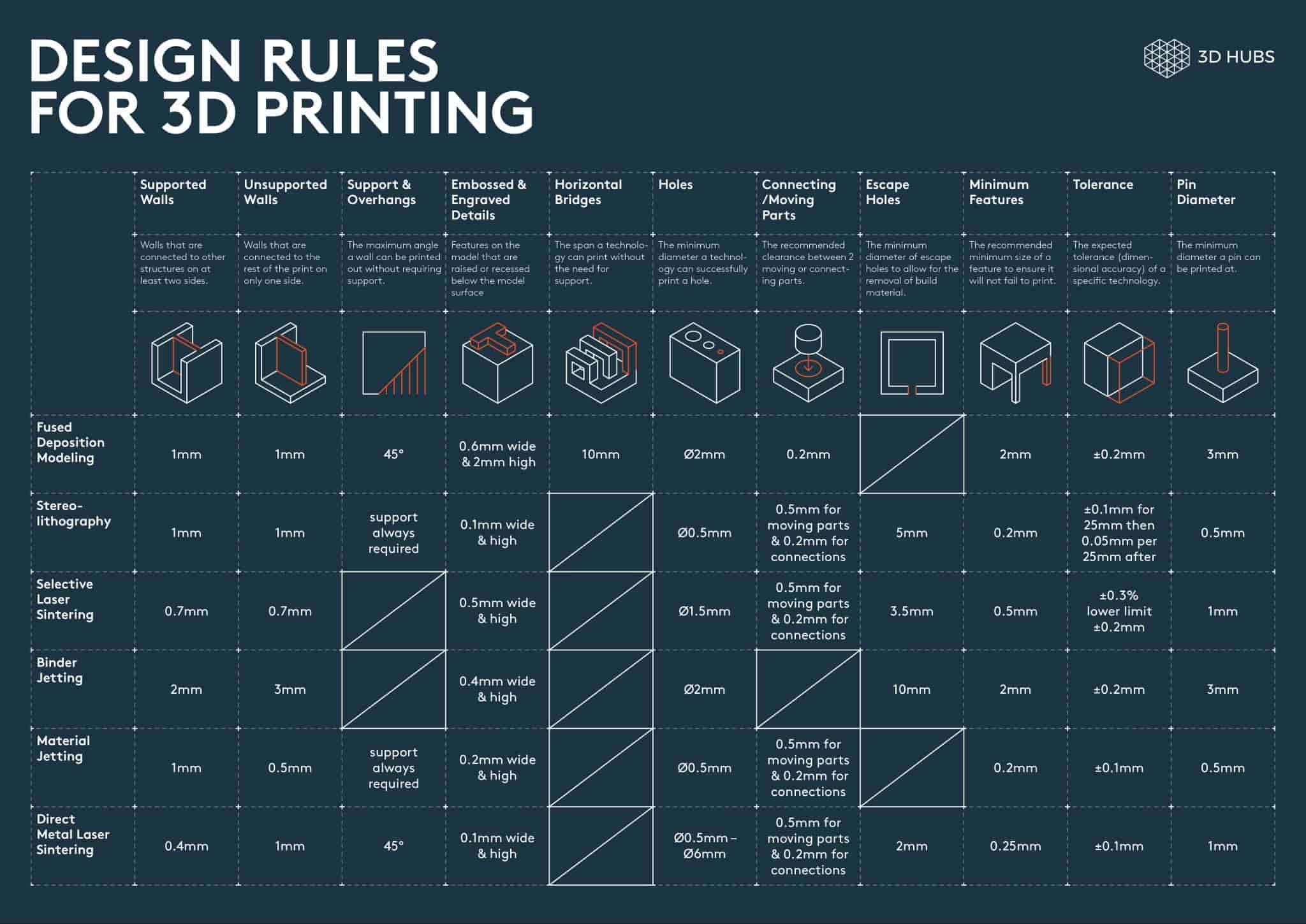
Test the design rules for your 3D printer(s)
Individual assignments:
Design, document and 3D print an object (small, few cm3, limited by printer time) that could not be easily made subtractively.
3D scan an object (and optionally print it).
Instructors for this week:Mufeed Saheen and Jogin.
Overview of Group Assignment
In this week group assignment, we explored the basics of 3D printing and learned about different additive manufacturing technologies. We studied the Bambu Lab A1 3D printer, its features, safety precautions, and slicing workflow using Bambu Studio. To understand the printer's capabilities and limitations, we printed a calibration model and tested parameters such as overhangs, bridging, dimensional accuracy, and clearances. The results helped us understand important design considerations for creating better FDM 3D prints with reducing print failures.
Printer & Material
- Bambu Lab A1 FDM Printer
- eSUN PLA-Basic filament
- 0.4 mm nozzle
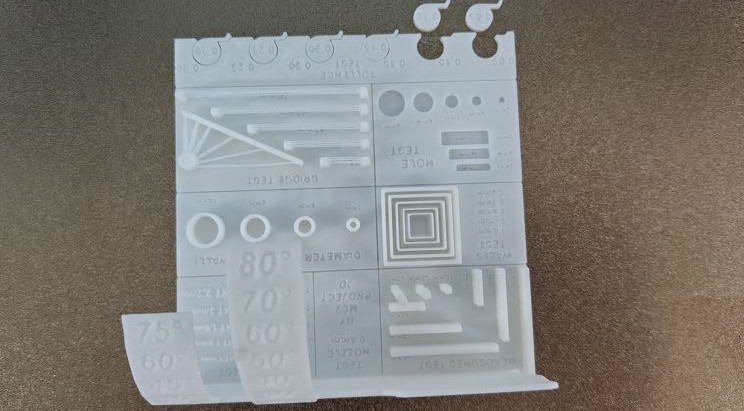
Overhang & Bridging
- Overhangs printed cleanly up to 45°
- Bridges worked reliably up to 20 mm
- 25 mm bridge showed visible sagging
Dimensional Accuracy
- Holes printed ~ 0.4 mm smaller
- 6 mm cylinder : 5.74 mm
- 8 mm cylinder : 7.75 mm
Clearance Test
- 0.05-0.10 mm : fused
- 0.15 mm : movable with friction
- 0.20-0.25 mm : smooth movement
- 0.30 mm : loose fit
3D Printing
Whenever I think about how 3D printing works —material coming out of a small nozzle and forming shapes layer by layer—it reminds me of food.
Like in Kerala households, when making noolputtu / idiyappam, the dough is pressed through a mould and comes out as thin strands. Mount them on the idiyappam maker,
and you can see the strands coming out and forming a circular shape.
Or even like jalebi, where the batter comes out of a nozzle and is drawn into circular patterns to form the shape.
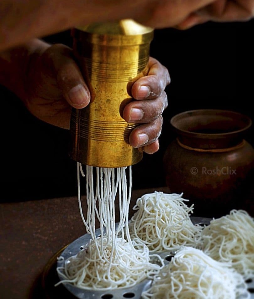
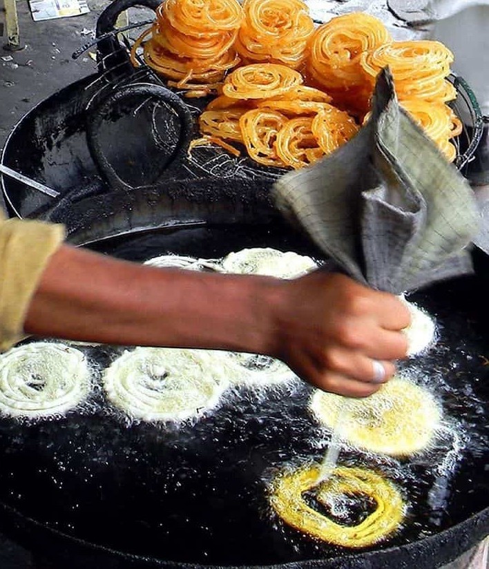
3D printing works in a very similar way. The filament melts inside the extruder, comes out as a thin line, and is placed layer by layer according to design.
In terms of rapid prototyping, iterative design, and small-scale production, 3D printing is ideal.
No moulds are needed.
You can print complex or organic forms.
You can literally build your imagination layer by layer.
Easy to iterate and reprint designs.
This makes it ideal for testing ideas/ designs and making quick iterations.
However, for mass production, traditional manufacturing methods are much faster once everything is set up. Methods like Injection moulding, Laser cutting, CNC machining are more efficient for large quantities.
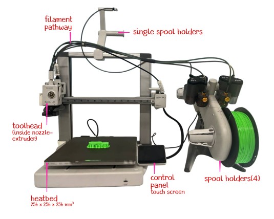
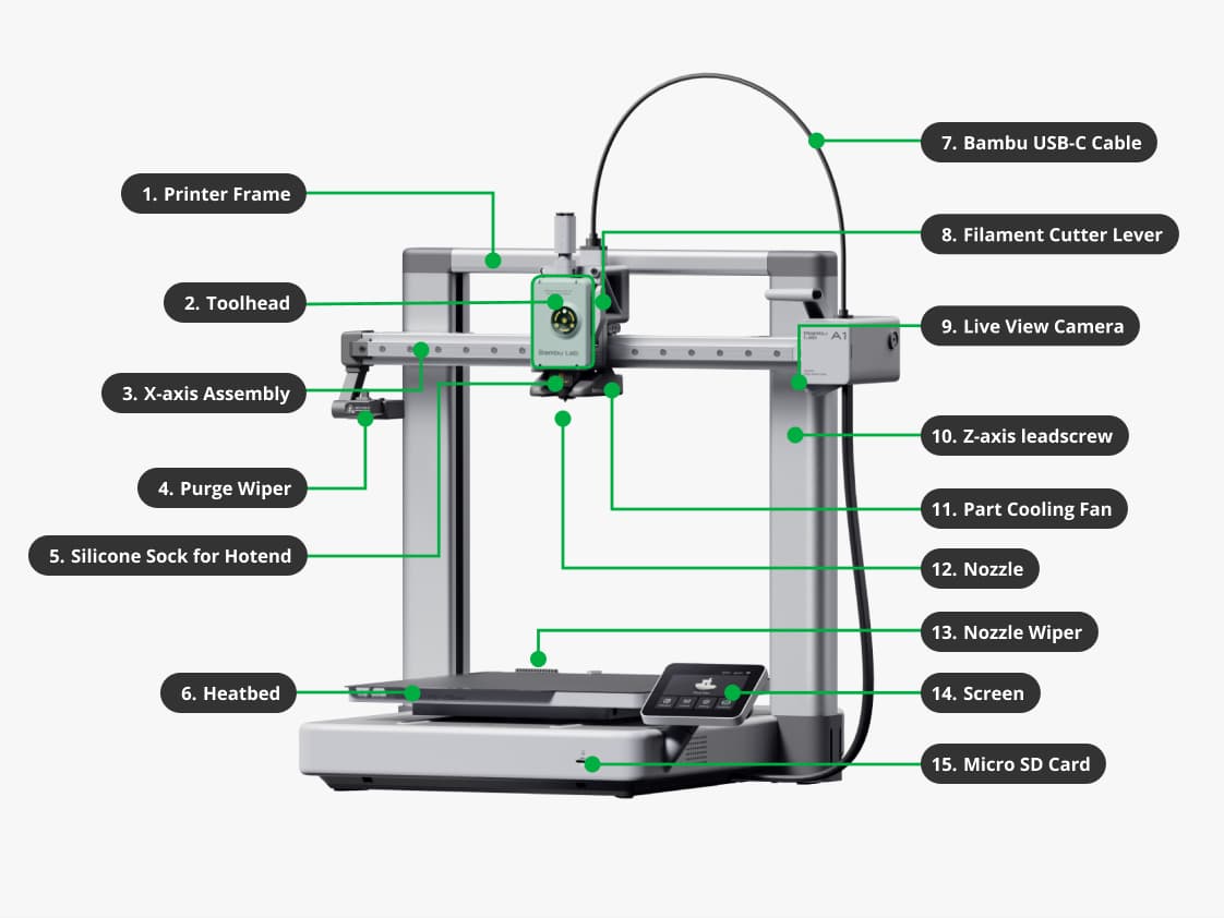
Machine Overview
Bambulabs A1 Mini
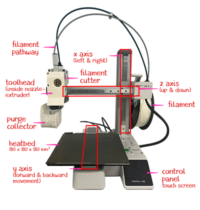
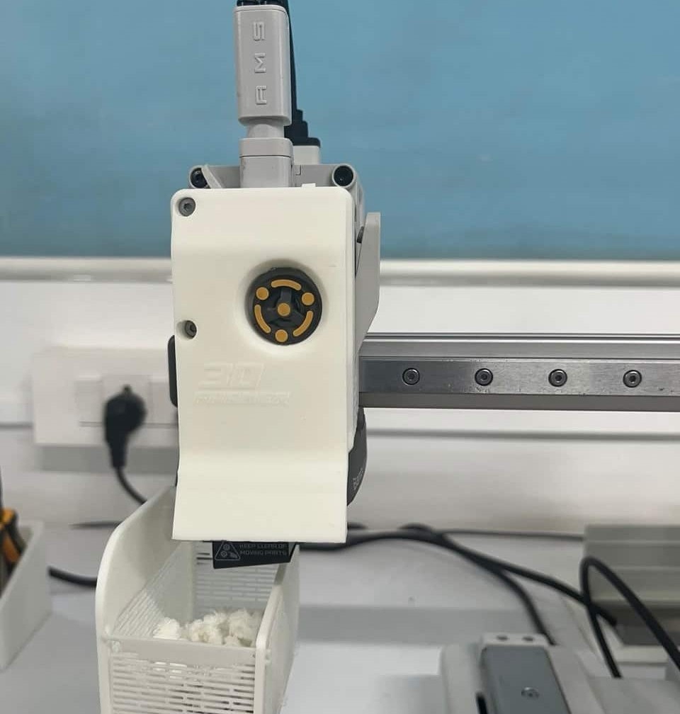
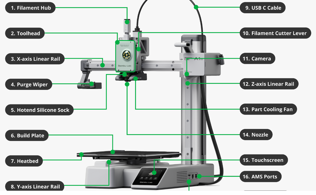
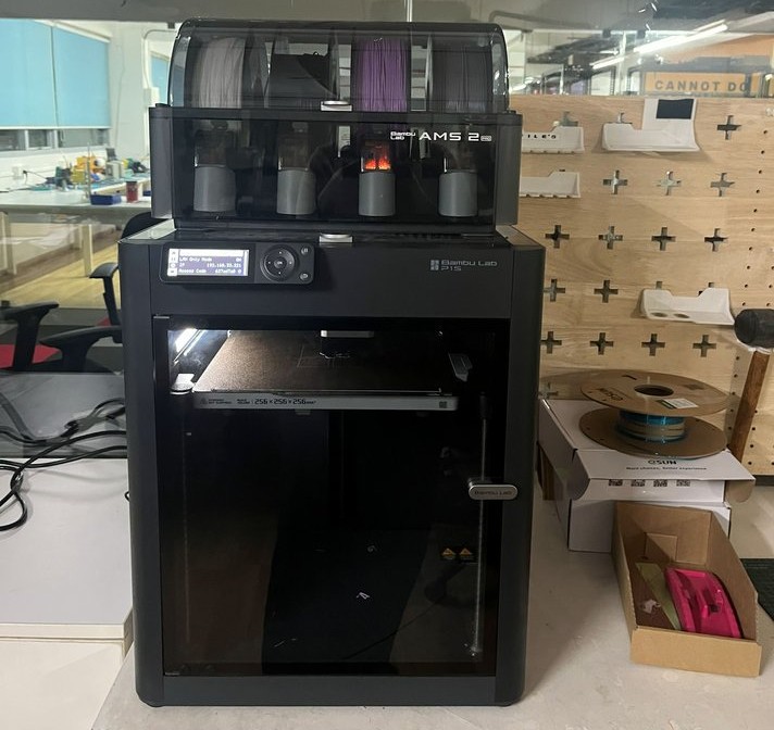
Bambu Lab A1
- Build Volume: 256 x 256 x 256 mm
- Nozzle: 0.4 mm
- Max Nozzle Temp: 300°C
- Max Bed Temp: 100°C
- Layer Height: 0.08 - 0.28 mm
- Max Speed: 500 mm/s
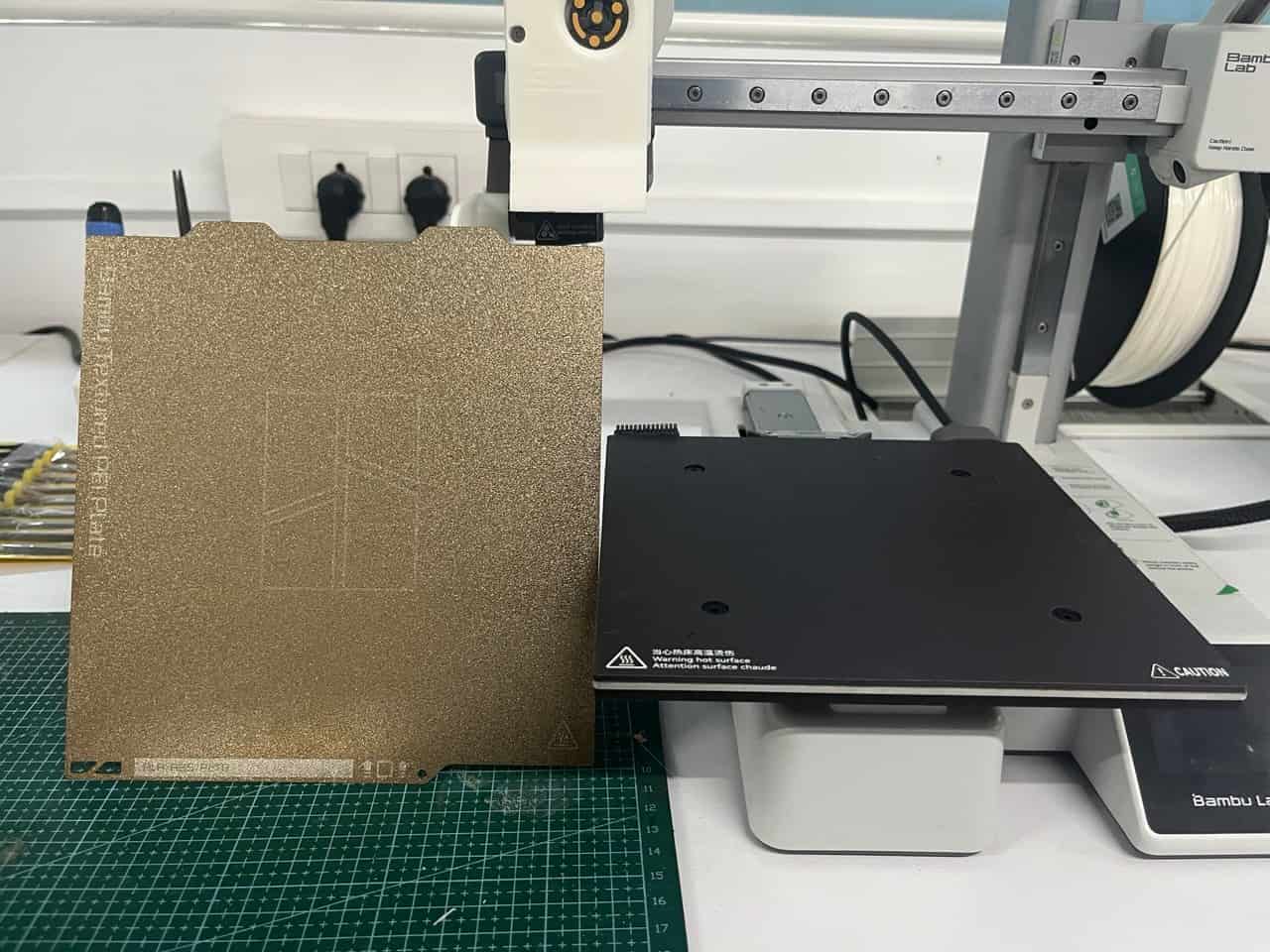
- Build Plate: PEI Spring Steel
Bambu Lab A1 Mini
- Build Volume: 180 x 180 x 180 mm
- Nozzle: 0.4 mm
- Max Nozzle Temp: 300°C
- Max Bed Temp: 80°C
- Layer Height: 0.08 - 0.28 mm
- Max Speed: 500 mm/s
- Build Plate: Textured PEI Plate
Nozzle Options
- 0.2 mm : High-detail prints, fine text, miniatures
- 0.4 mm : Standard nozzle for general-purpose printing
- 0.6 mm :Faster printing and stronger functional parts
- 0.8 mm : Large prints, thick walls, high-speed printing
Bambulabs A1
Filament Used:
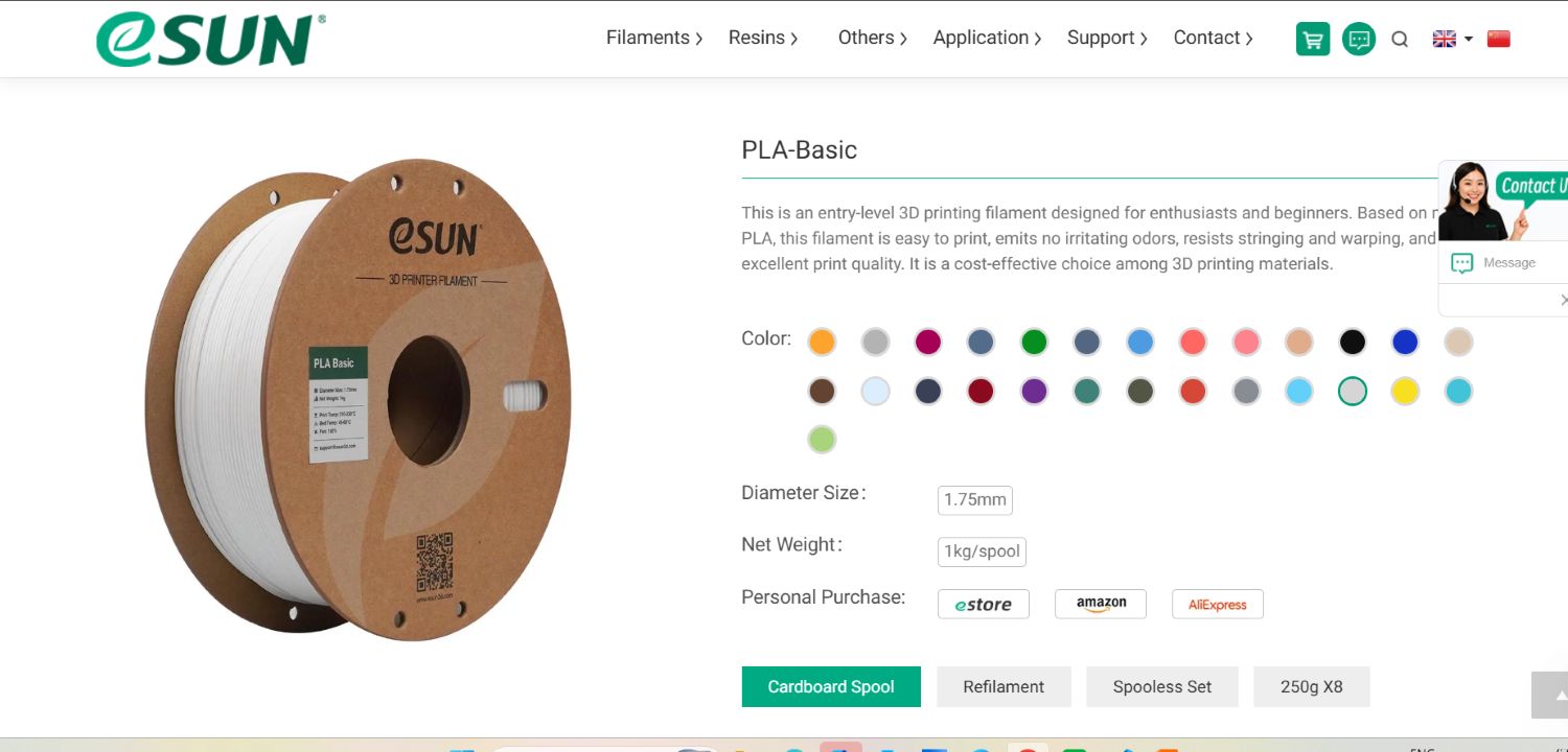
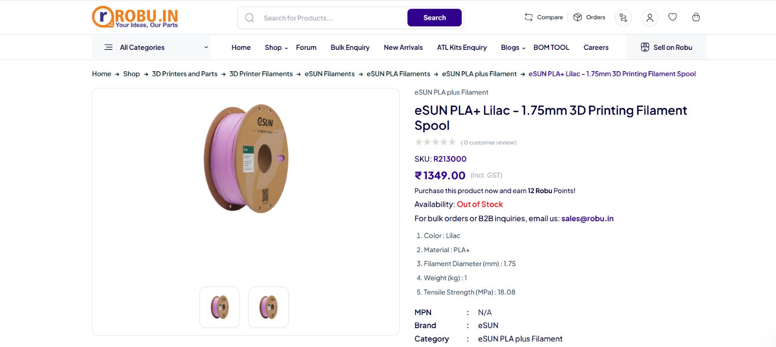
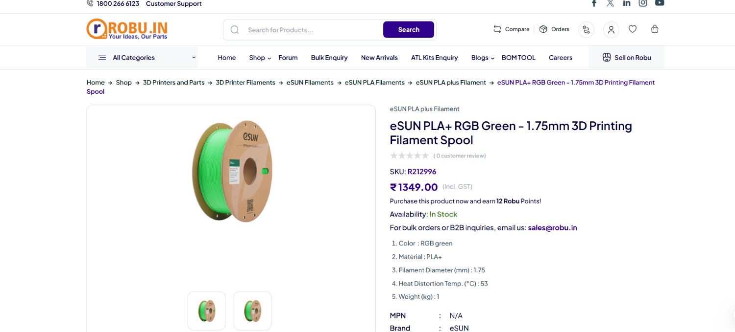
Source: White - ESUN lilac_ESUN - Robu Rgb_green_ESUN - Robu
1
Individual Task
What will i print?
I was thinking about what I should design. It has to be something that isn't
easy to make using a subtractive method. Finally, I agreed with my thoughts and
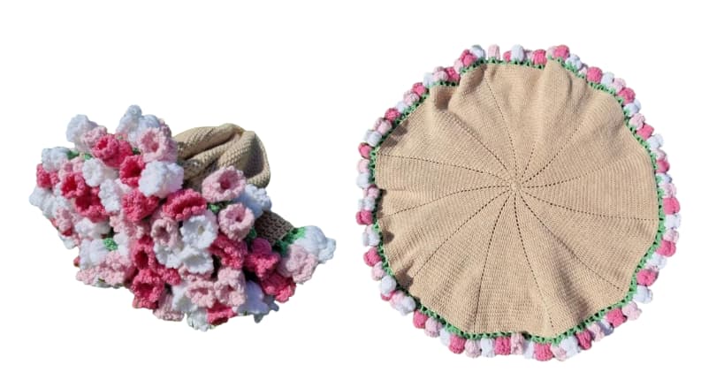
decided to make the trending crochet flower bouquet blanket.
I have done crochet before, and first of all, it requires a lot of patience.
For my first try, I watched YouTube videos and made a vest for my cousin.
It wasn't bad, actually. Another time, I made a small airpods holder with a cat paw design—again by watching YouTube.
Now I'm curious about how it would look if I 3D print it, and whether I can create this
design using 3D printing. However, I don't want it to have the same pattern as crochet.
2
Designing the model
To make the bouquet, I thought of creating a crochet mesh-like structure, or a neural-type pattern.
Before that, I need to figure out how to fold and unfold it into a circular blanket.
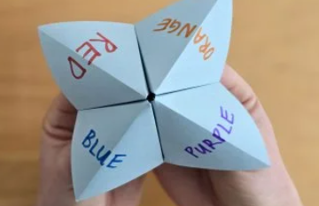
My instructor suggested using hinges. I was amused by how instructor took a piece of paper, folded it here and there,
tore a few parts, and then turned it into a circle.
I know how to make a square, and something that simple might be common thing for everyone, but I was fascinated by it.
The idea is to divide the circle into triangular sections and add hinges between them to allow 180-degree movement,
and connect them so the structure can fold and unfold properly.
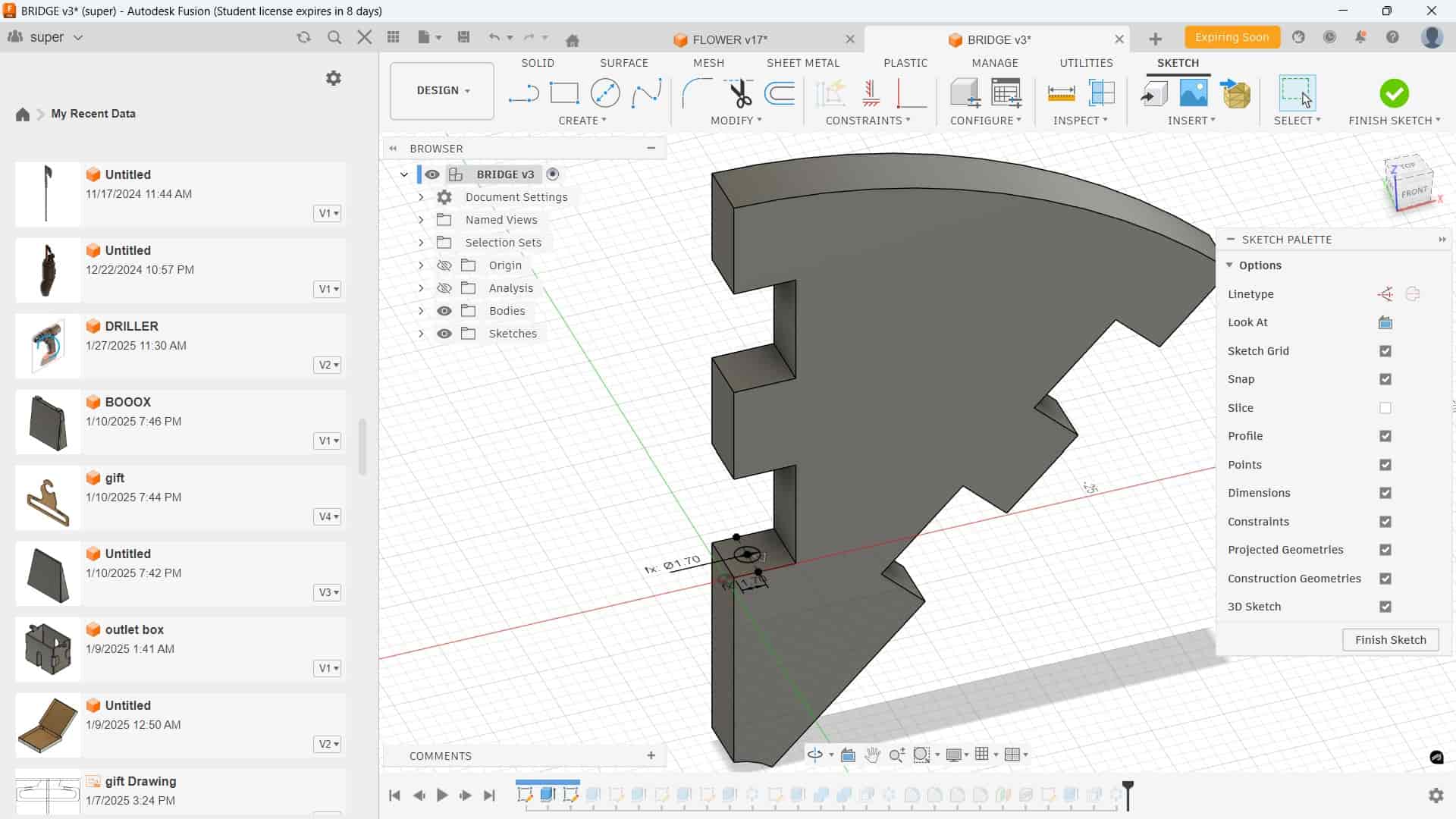
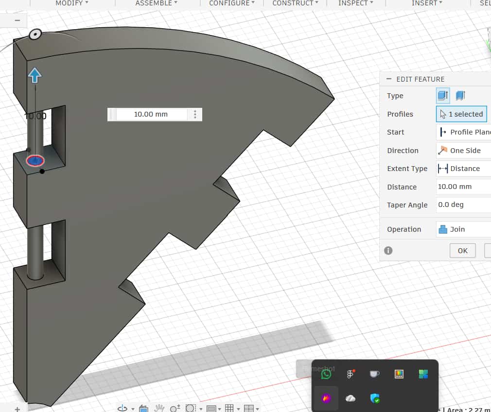
Flaps:
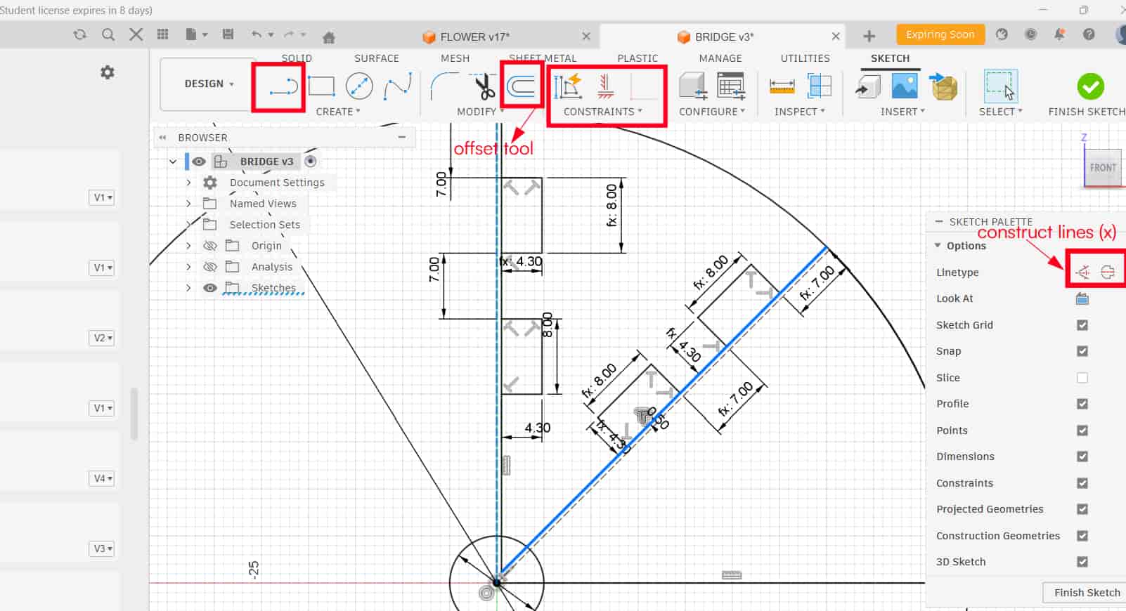
I started by drawing a circle and sketching a 45° triangle inside it. Then used the Offset Tool with a value of 0.5 mm. The first sketch line was converted into a construction line using the X Key, and created a slot profile. After completing the sketch, used Extrude to form the flap body.
Mistake I Made
I applied Circular Patternfor the flap and didn't add clearance. This caused the flaps to overlap at the edges.
How I Fixed It
Hinge
Instructor told me to add clearance. That's when I realized movement needs space. From the group assignment's test print data checked about clearance values. I added a clearance of 0.5 mm, and their is enough clearance between the flaps, so it worked properly.
For the hinge pins, I finalized a diameter of 1.7 mm after several iterations. I tested the movement using Joints and also the Move Tool inside the software. Each flap had four hinge pins, and they were joined to the flap body.
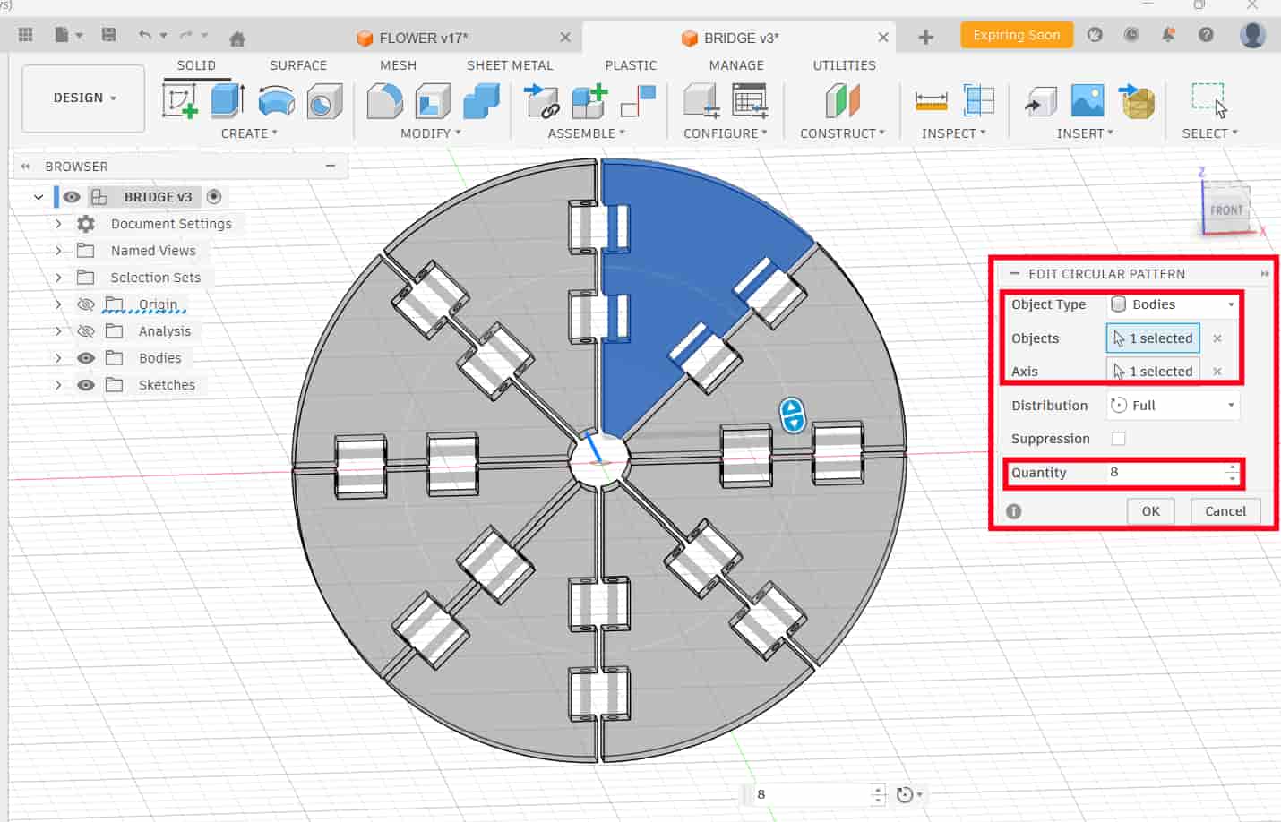
circular pattern
used to duplicates a body evenly around an axis. selected the flap body, chose the Y-axis as the rotation axis, and set the quantity to 8 to create 8 flaps arange in circular form.
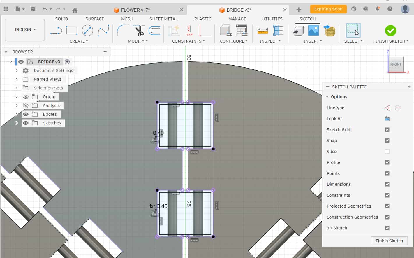
After that, I created the hinge body (outer holder), i don't know what to call it so let it be hinge body. I selected the front plane, projected the slot from the flap using Project Tool(P), sketched a rectangle, offset it by -0.4 mm, and extruded it as a new body to maintain proper clearance.
To create the pin slots inside the hinge body, I used the Combine Tool.
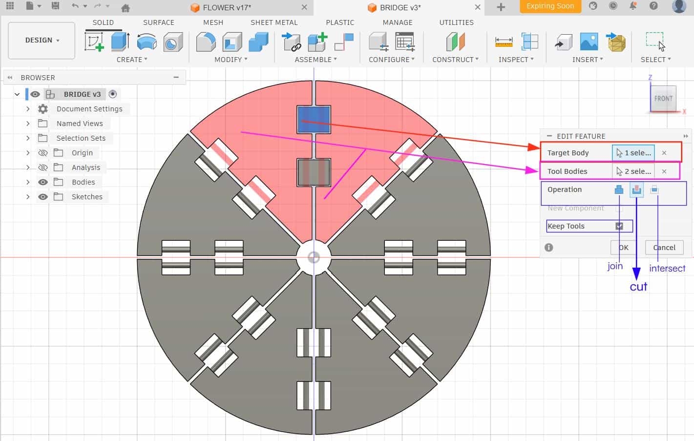
combine
allows us to join, cut, or intersect bodies. In the Combine dialog, we must define
the Target Body, Tool Bodies, and the Operation.
I selected the hinge body as the Target Body(the body to be modified) and the flaps as the Tool Bodies.
Then I chose the cut operation so the hinge pins would
remove material from the hinge body and create the pin cavity.
In the dialog box, I enabled Keep Tool Bodies. This is important because if it is unchecked,
the tool bodies would be deleted after the cut.
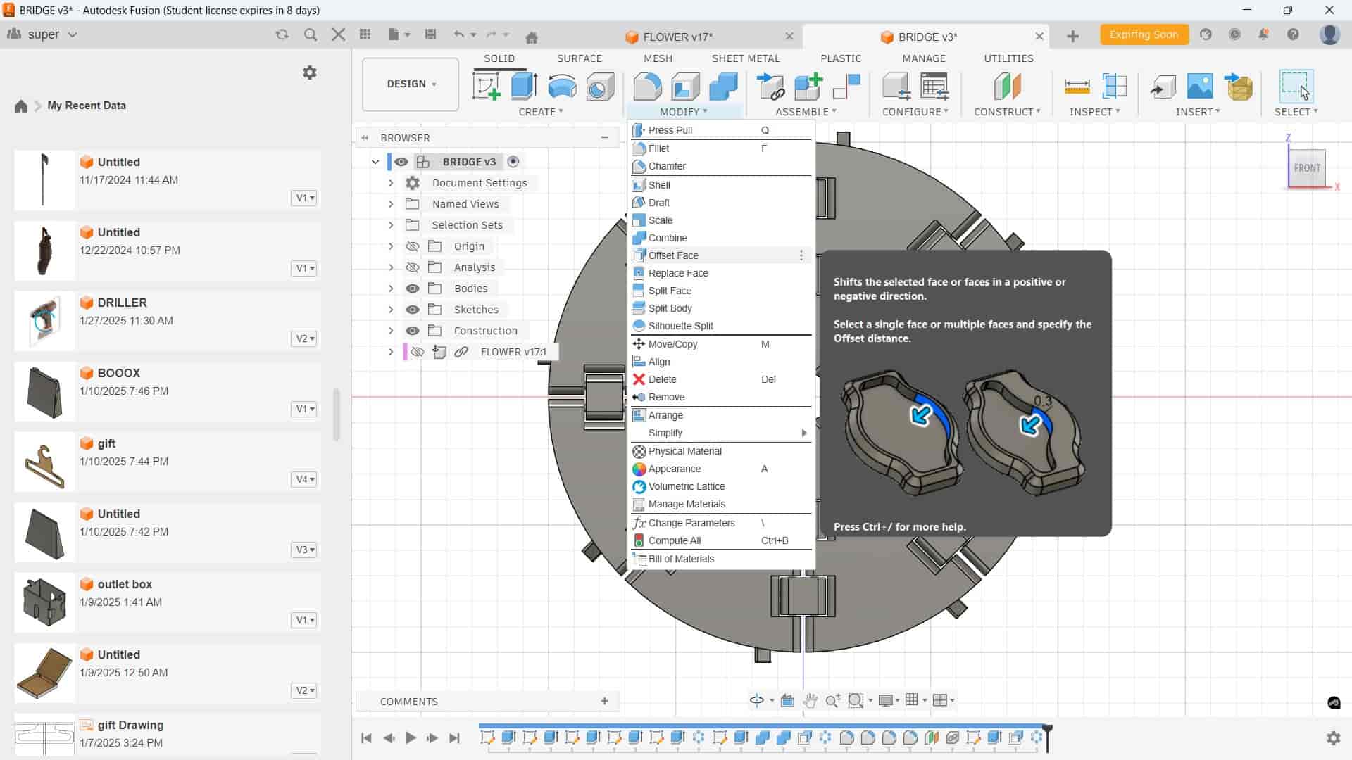
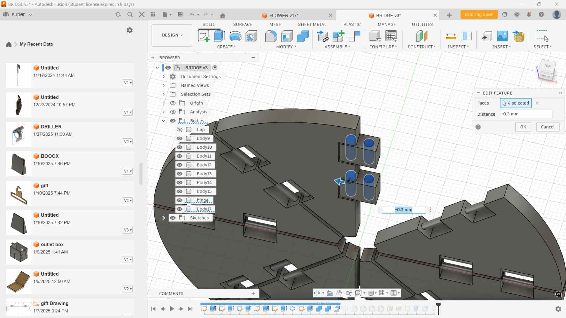
offset
Modify >> offset to adjust the pin cavity. Offset allows us to increase or decrease the size of a selected face by a specific distance.
I used it to create clearance of 0.3mm so the hinge pin could rotate smoothly without friction.
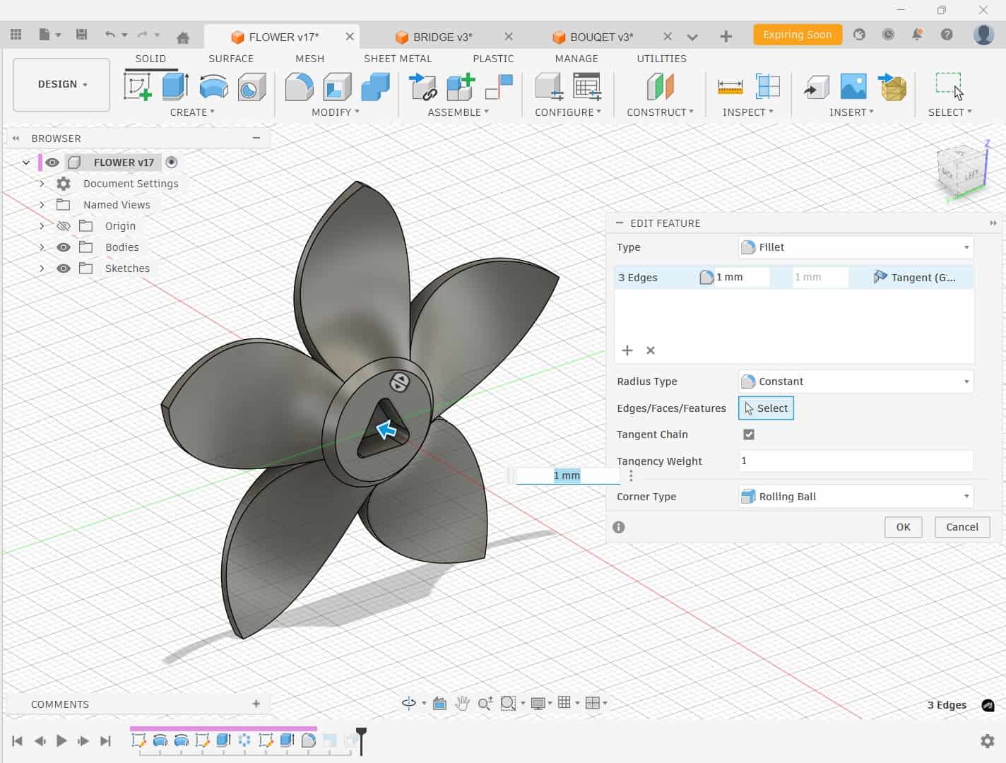
I added Fillet (1.5 mm) to the flaps and hinge edges. This was important because sharp edges can interfere during 180° rotation. With proper clearance and rounded edges, the flaps rotate smoothly without overlapping.
This entire design was iterative. Most movement testing was done directly inside the software before printing. Based on the group assignment test prints, a clearance of around 0.3 mm was finalized as suitable for smooth rotational movement on our printer.
Design Parameters
| Feature | Value | Purpose |
|---|---|---|
| Sketch Offset | 0.5 mm | Initial flap shaping |
| Flap Clearance | 0.5 mm | Prevent overlap between flaps |
| Hinge Pin Diameter | 1.7 mm | Rotational connection |
| Circular Pattern Quantity | 8 | Radial arrangement of flaps |
| Hinge Body Offset | -0.4 mm | Maintain housing clearance |
| Pin Cavity Clearance | 0.3 mm | Smooth hinge rotation |
| Fillet Radius | 1.5 mm | Avoid edge interference |
Flower
For creating the flower part, I referred to a YouTube tutorial and followed the general workflow shown in the video: Flower Modeling Reference Video . I adapted the steps according to the dimensions required for my design.
The modeling process mainly involved creating a sketch profile and using the
Revolve feature to generate the base form.
After that, I applied the Circular Pattern tool
to replicate the petal structure evenly around the y-axis.
For attaching flower on top of the flaps, I created a press-fit connection.
I designed a hole on the flower base and a corresponding triangular peg on the flap bases.
The traingular hole having a 60 degree angle and a 0.3 mm clearance and added fillet to edges of 1mm.
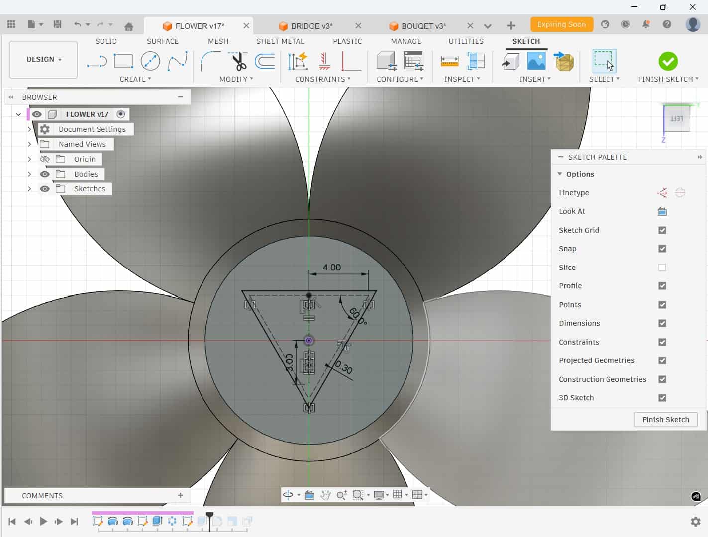
Other thing i found when inserting flower to flap window that the flower overall size was bigger than expected, so used the Scale tool to reduce it.
The peg was designed to fit snugly into the hole, ensuring a secure attachment.
for that imported the flower model into the flap design file, positioned on distance to flap on top and used construction plane placed it in distance on the top of the flap.
Then created sketch on the construction plane, projected the hole from the flower base and flap curve using project tool, and positioned hole sketch properly on curve projection.
Finally extruded the peg and offset of -0.3mm to ensure a smooth fit.
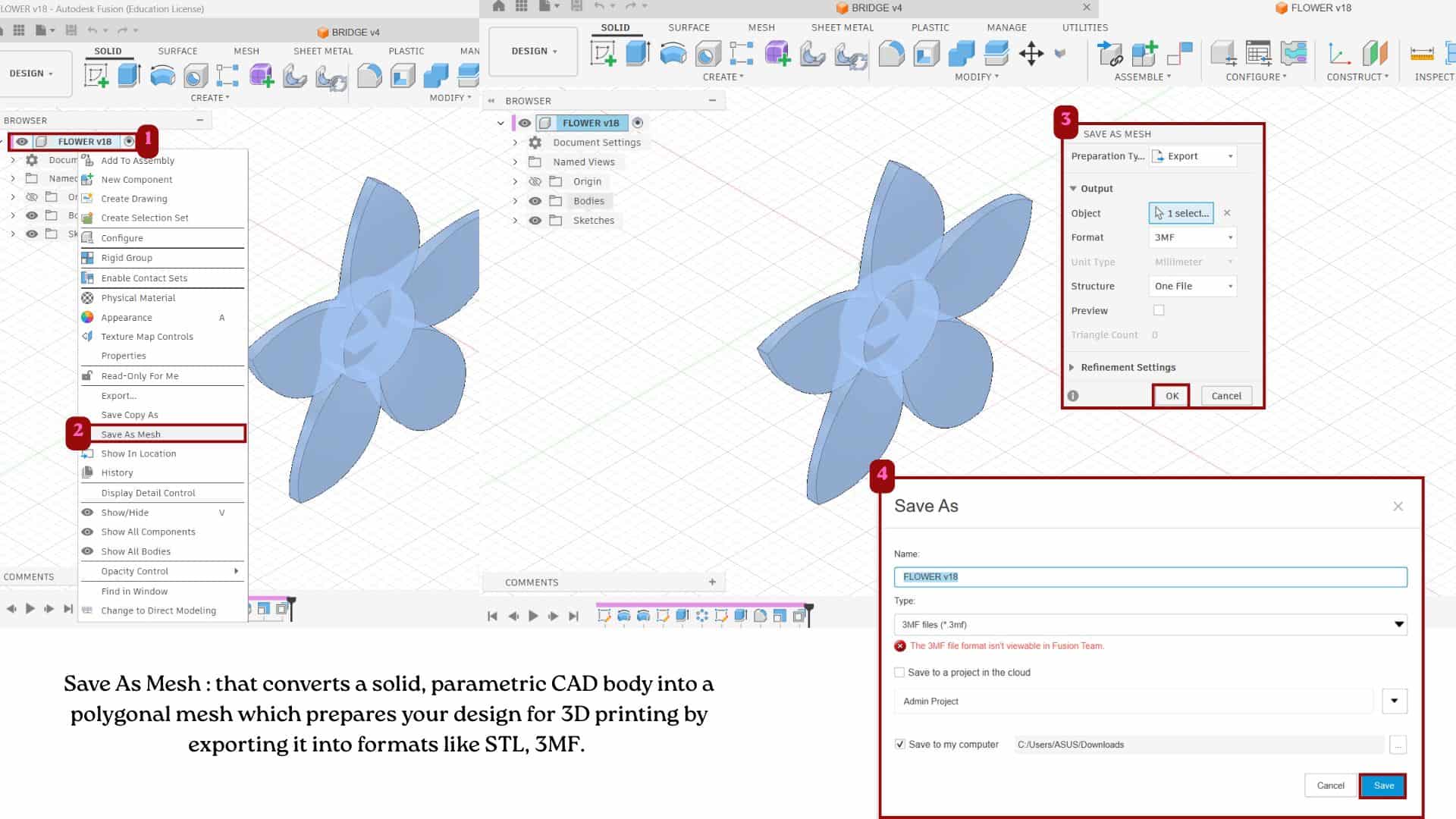
Then for saving it has 3mf file: right click on the component/body >> save as mesh >> format: 3mf >> save it.
3
Importing to Bambu studio
Bambu studio is a open source 3d printing slicer software by bambu labs which can be used for connect with the 3d printers, converting the stl,3mf such files to g-code. Features like:
- Import 3D files such as STL, OBJ, STEP, and 3MF.
- Move, rotate, scale, and arrange models on the build plate.
- Adjust print settings such as layer height, infill, speed, supports, and temperatures.
- Preview the print layer by layer before printing using slice tool.
- Estimate print time and filament usage.
- Generate G-code and send the file directly to the printer.
- Monitor the printing process when connected to a Bambu Lab printer.
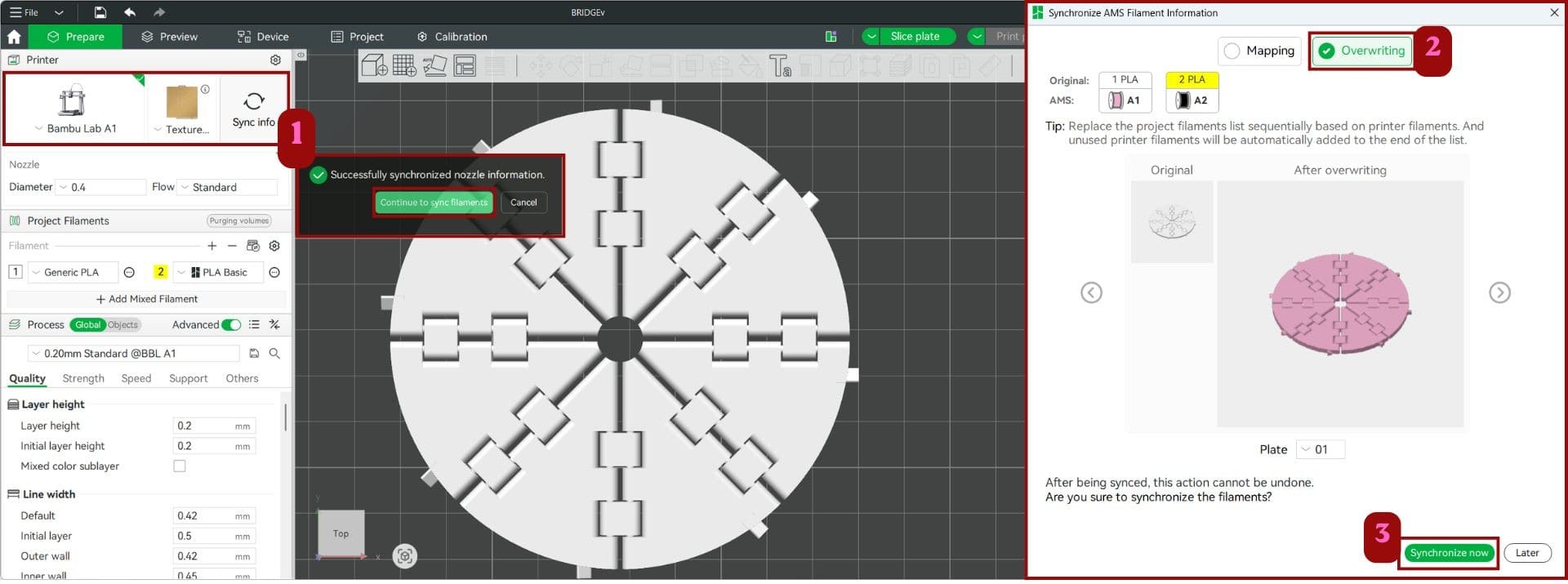
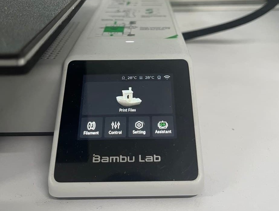
For syncing the bambu studio with the printer, use select the printer connected with the account then click "sync info" >> which opens a dialog box - select "overwriting". This synced the printer information with Bambu Studio, making sure both had the same settings before sending the print job.
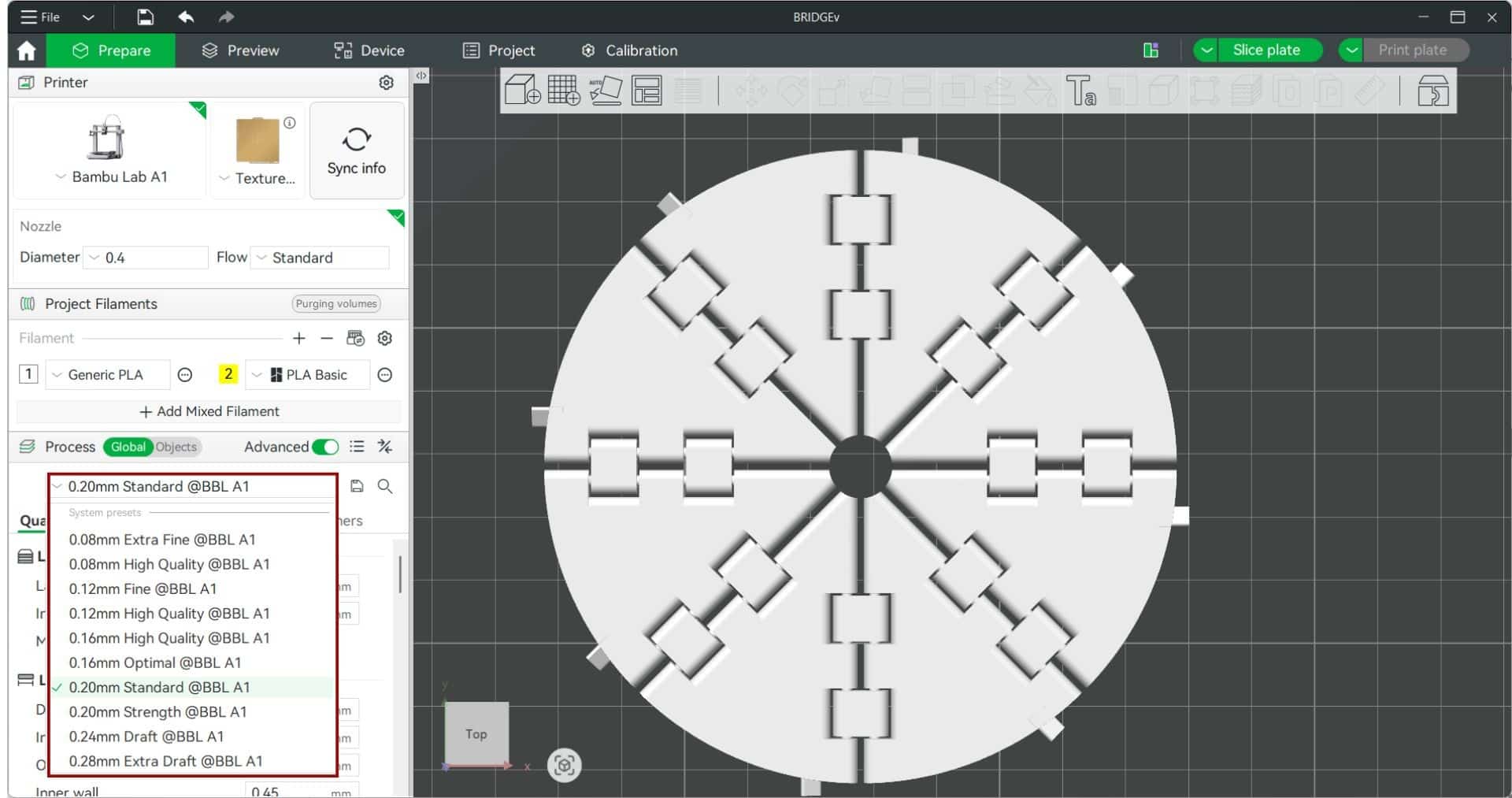
Selected layer height, I used the 0.20 mm Standard profile, as it provides a good balance between print quality and printing time, making it is commonaly suitable for general-purpose prints.
Lower layer heights such as 0.08 mm produce finer details, while higher layer heights such as 0.28 mm reduce printing time but result in more visible layer lines.
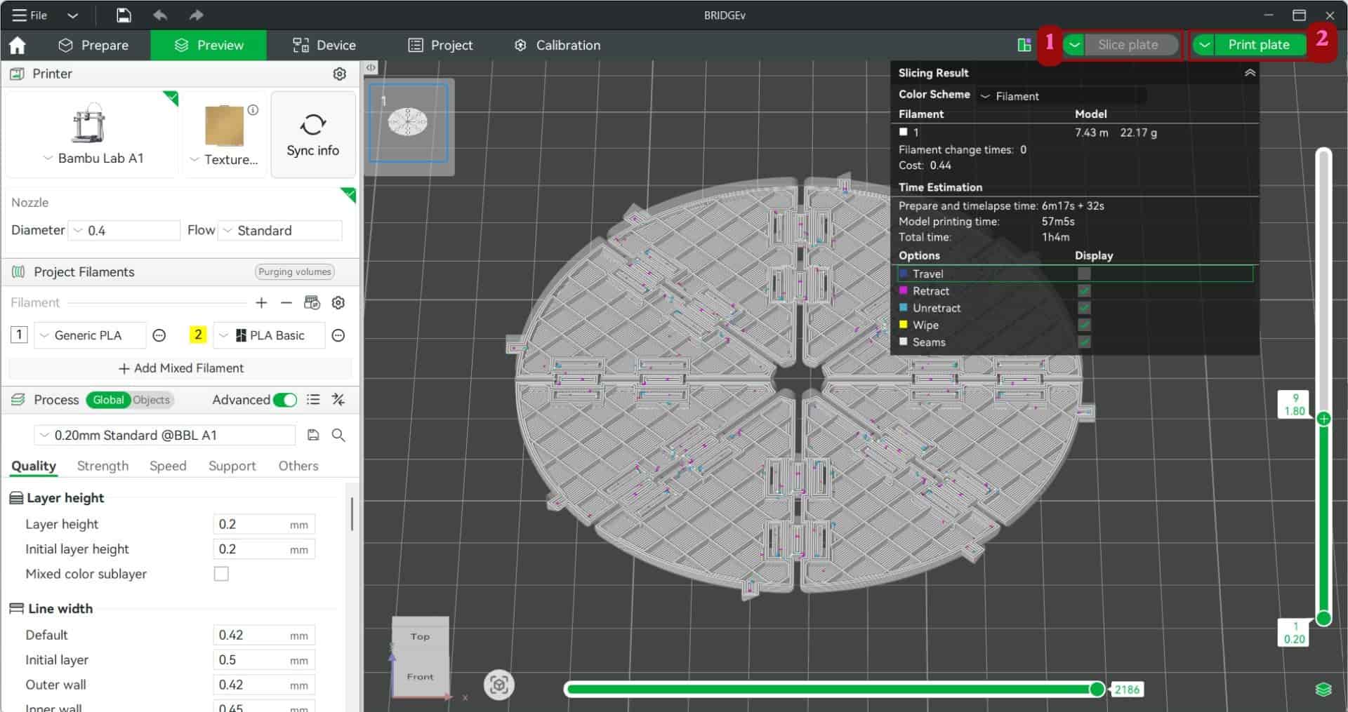
After adjusting the print settings, I clicked Slice Plate to generate the toolpath and G-code for the model. This showed the preview the layers, estimate the print time, how much filament be used and check for any issues before sending the file to the printer.
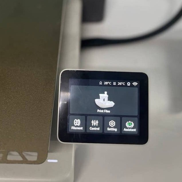
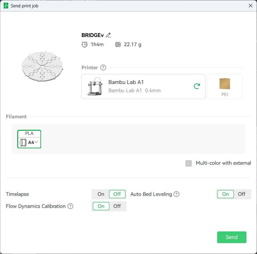
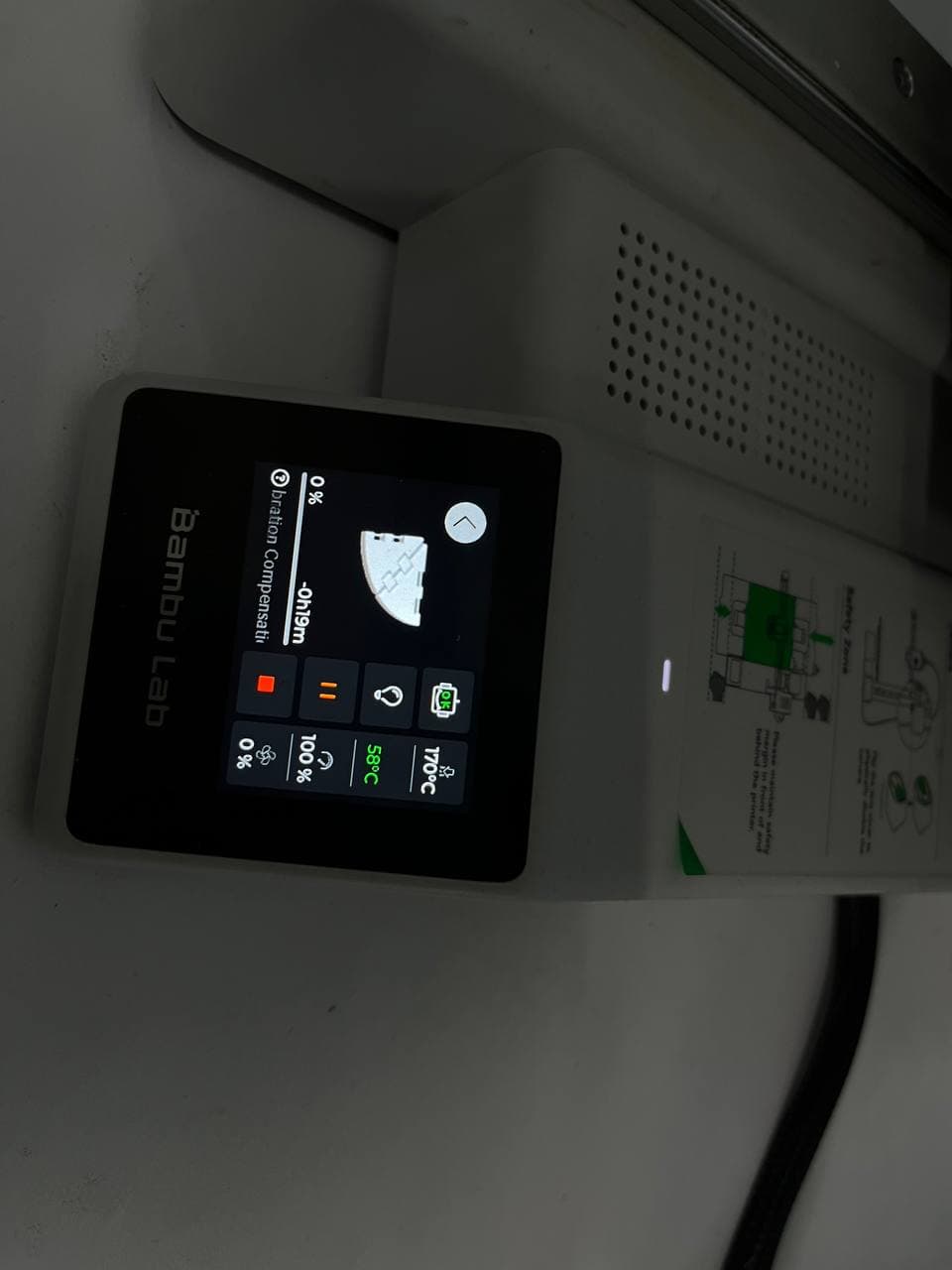
Once everything looked fine, I clicked Print Plate. The printer then performed automatic calibration (which is the process where the printer automatically checks and adjusts settings such as bed leveling and nozzle position before printing) and started printing.
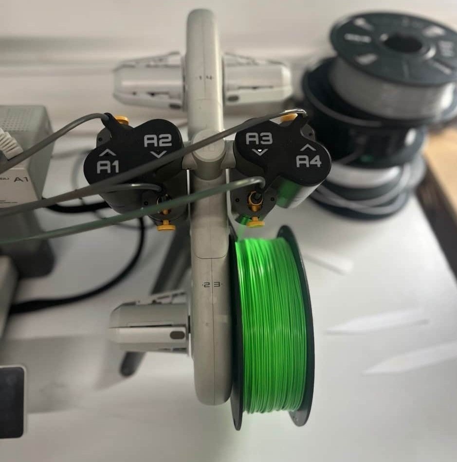
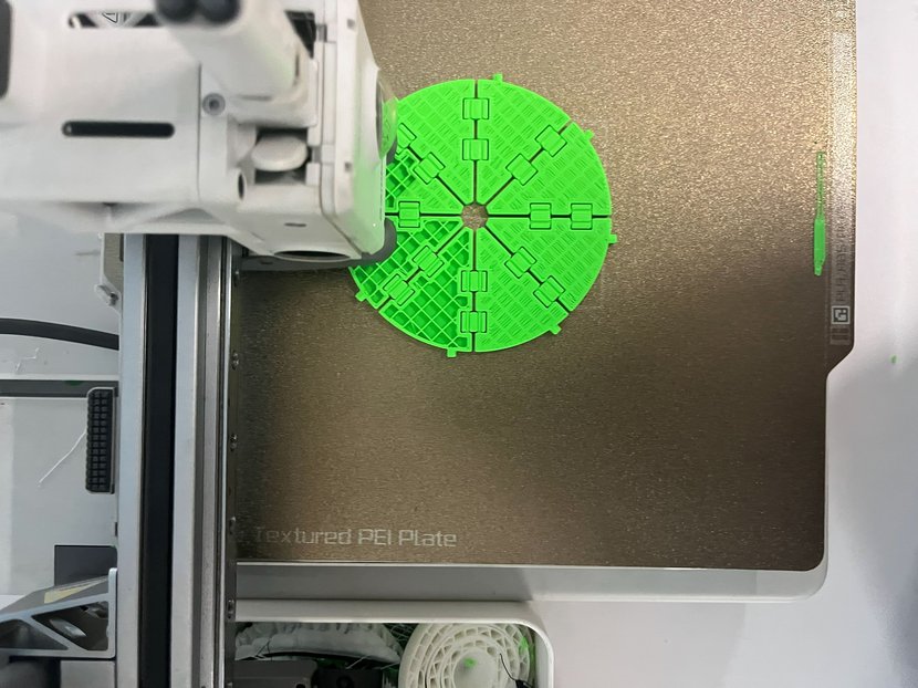
Actually i printed it in green colored PLA, as i forgot to take screenshots in the process and took it later on while documenting.
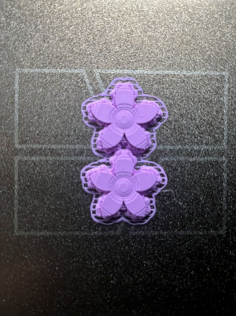
Flower
For printing the flower model, I used two printers. The Bambu Lab A1 Mini was loaded with white PLA, while the Bambu Lab P1S with AMS was loaded with lilac PLA
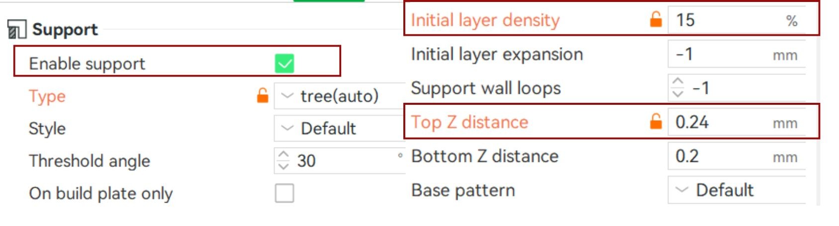
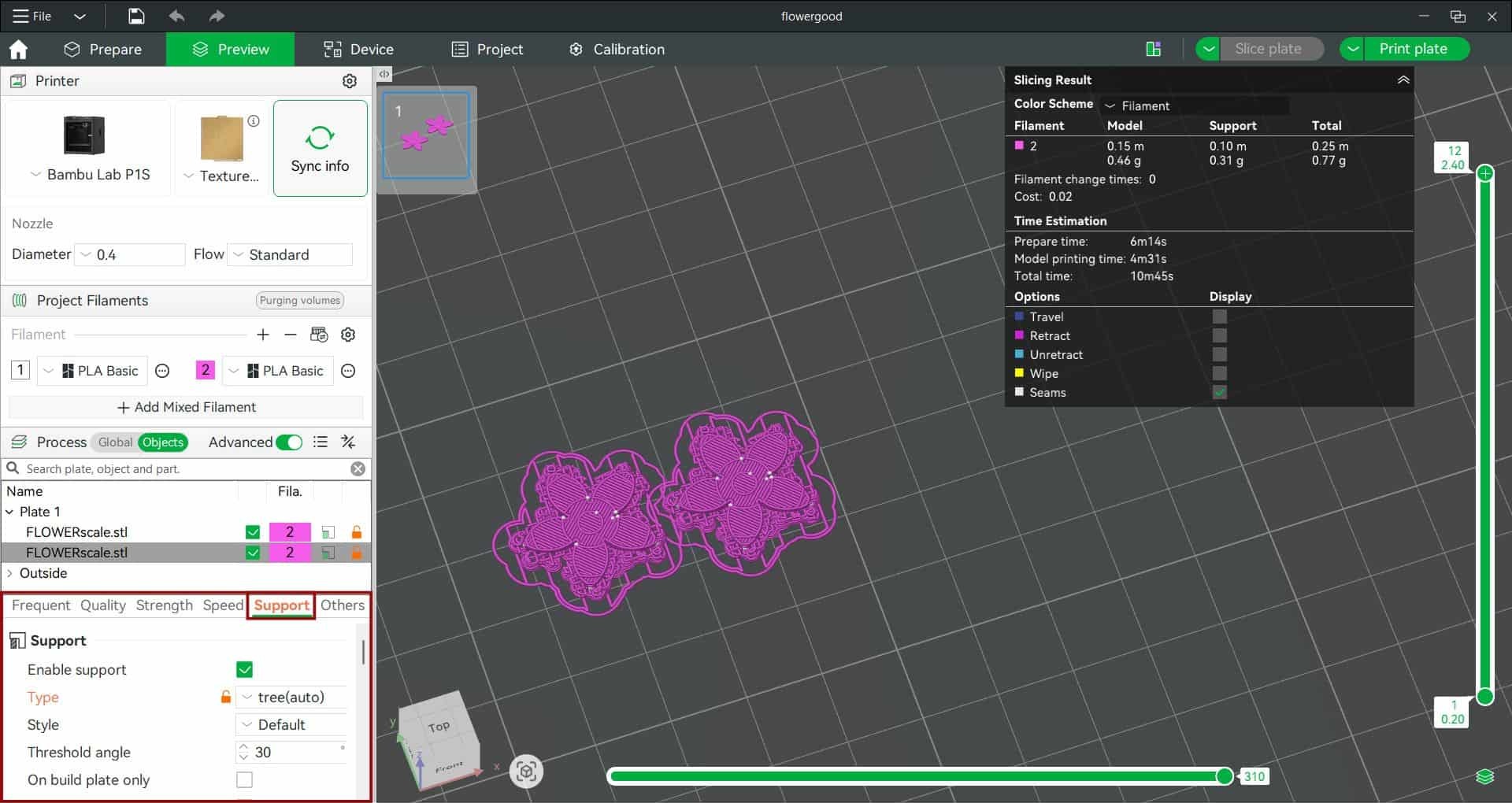
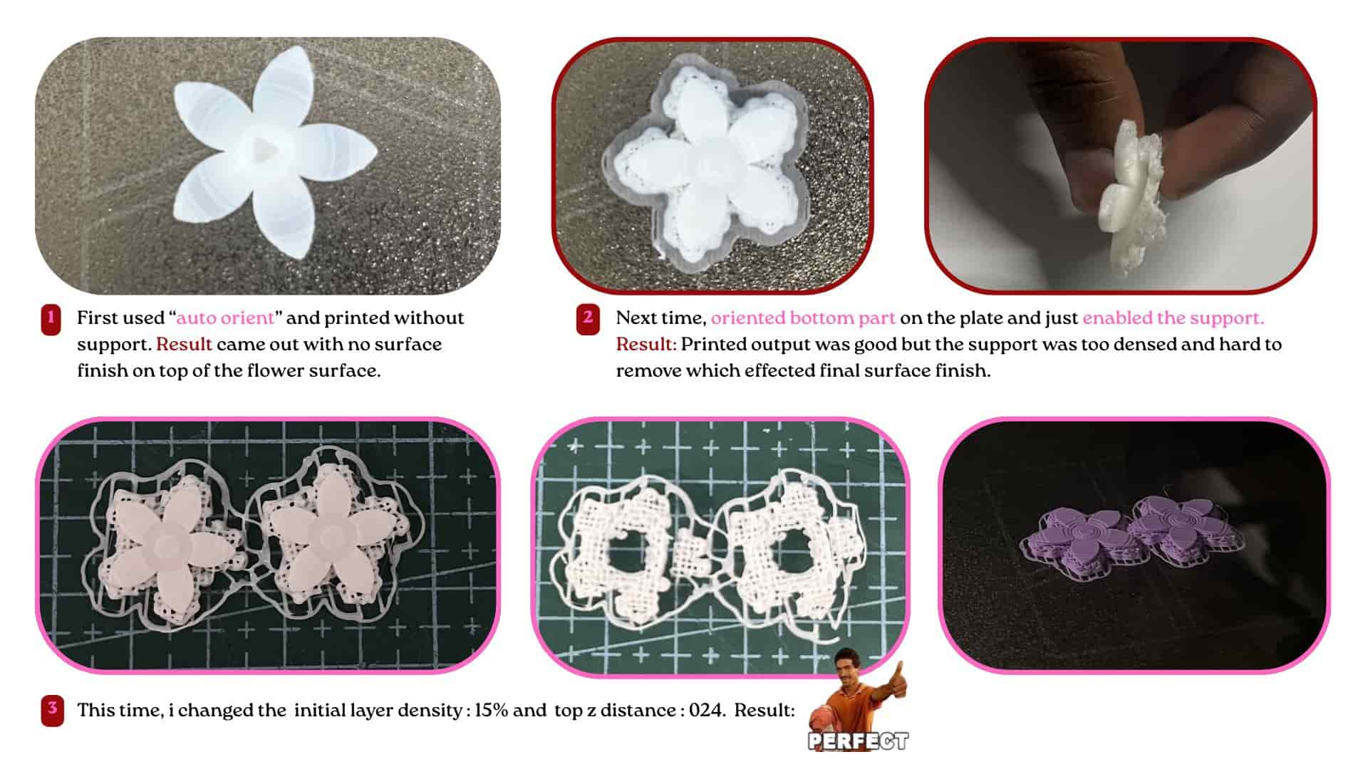
After a few test prints, I found that an Initial Layer Density of 15% and a Top Z Distance of 0.24 mm worked well for this model.
Support
a temporary structure printed to hold up overhanging or floating parts of a model to help the model print properly.. It is removed after the print is finished.
Initial Layer
Density
controls how dense the support interface is where the support touches the model.
Top Z Distance
the gap between the support and the model. This small gap prevents the support from sticking too strongly to the print while still providing enough support during printing.
Brim
an extra layer of material printed around the base of a model to improve bed adhesion and reduce the chances of the print lifting or warping during printing.
4
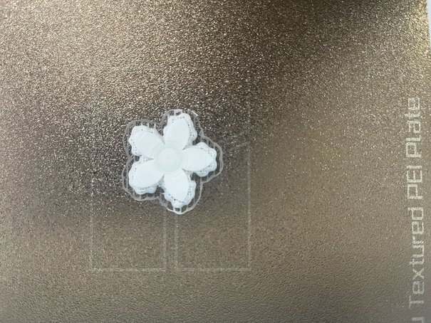
Test Print and Print Results
For testing the print-in-place flap hinges, I printed only two flaps connected by a hinge to check whether they could fold freely without any restrictions. I used the Bambu Lab A1 Mini with white PLA filament for this test.
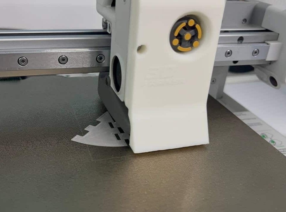
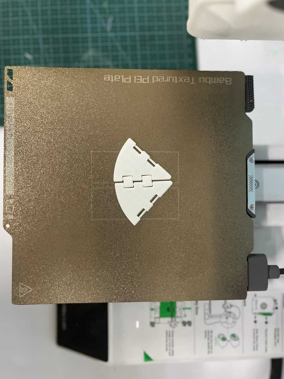
The print was successful, and the hinge worked as intended, allowing the flaps to fold smoothly.
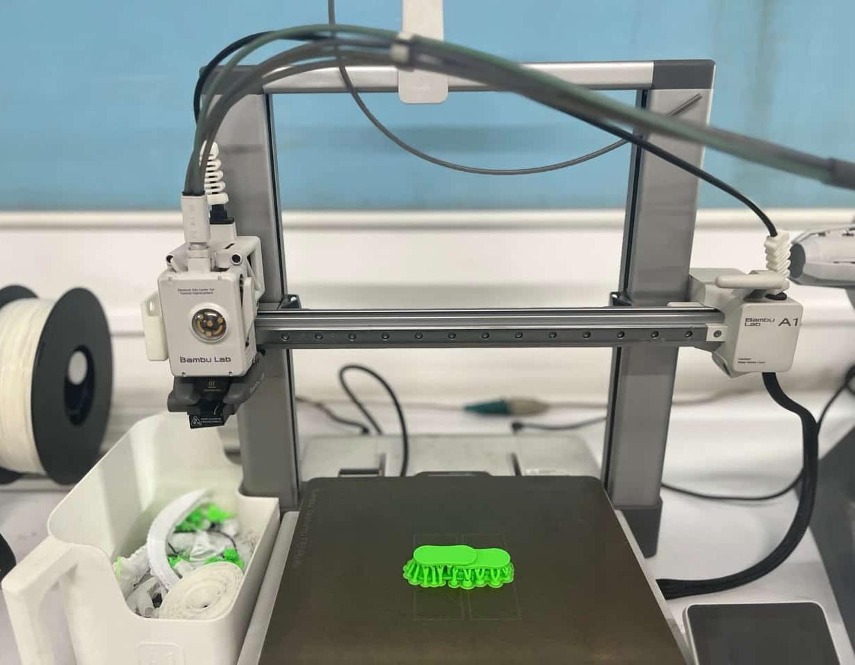
After confirming that the hinge mechanism worked properly, I printed the complete model on the Bambu Lab A1 using green PLA filament. The final print was successful, and all the flaps folded as intended.
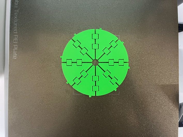
One thing I learned is that it is better to test a small part of a model before printing the whole thing. This approach helped me avoid wasting material and saved several hours of printing time that could have been lost if the full model had failed.
Post Processing: Tweezers and pliers are used to remove the support and extra debris.
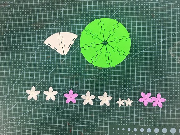
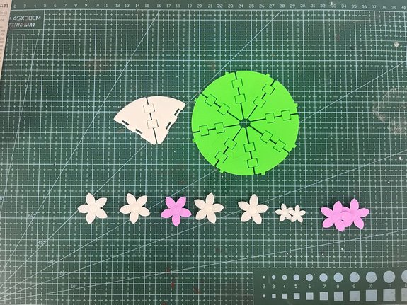
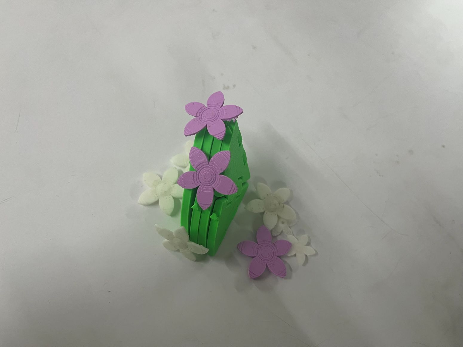
Final Outcome: I'm happy with how the final print turned out. If I were to improve it in the future, I would refine the tab-and-slot connection between the flaps and the flower. Although the parts fit together well, there is still room for improvement in the fit and assembly. Also like to experiment with different tab placements and print the flower in different sizes.
3D Scanning
The process of capturing the exact shape and geometry of a real-world object and converting it into a digital 3D model.
It is especially useful for objects that are difficult or time-consuming to model manually in 3D software.
By scanning, we can quickly generate a base model to work on instead of starting from scratch.
Bascially it allows us to capture reality with high accuracy,
including complex curves and organic forms.
It is widely used in areas such as gaming, animation, product design, reverse engineering, medical applications, and cultural preservation.
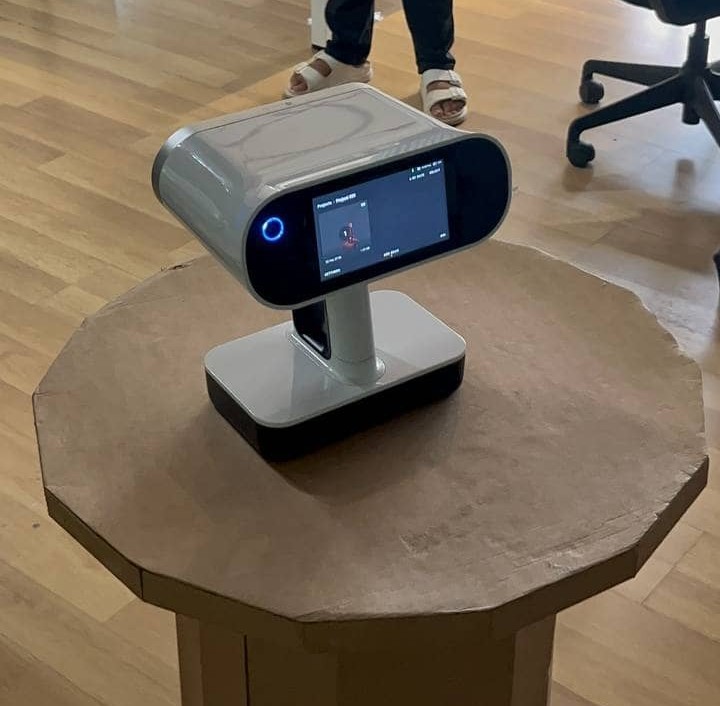
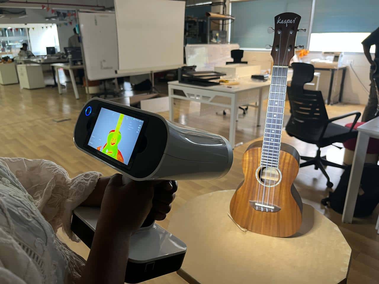
Artec Leo 3D scanner
In our lab, we have the Artec Leo 3D scanner to capture a physical object and convert it into a digital 3D model.
It works using structured light technology, projecting a light pattern onto the object while built-in cameras record how the pattern
deforms to calculate depth and geometry in real time. The device has its own screen and processor, so scanning can be done without a laptop;
a standalone wireless device.
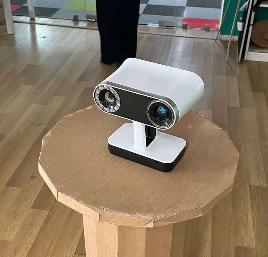
The scanner felt quite heavy for me to hold for a long time while scanning. The Artec Leo weighs approximately 2.6 kg.
After scanning, the data can be transferred to Artec Studio software for cleaning, alignment, and exporting as a 3D file such as STL for further use.
Tech Specs: Artec Leo
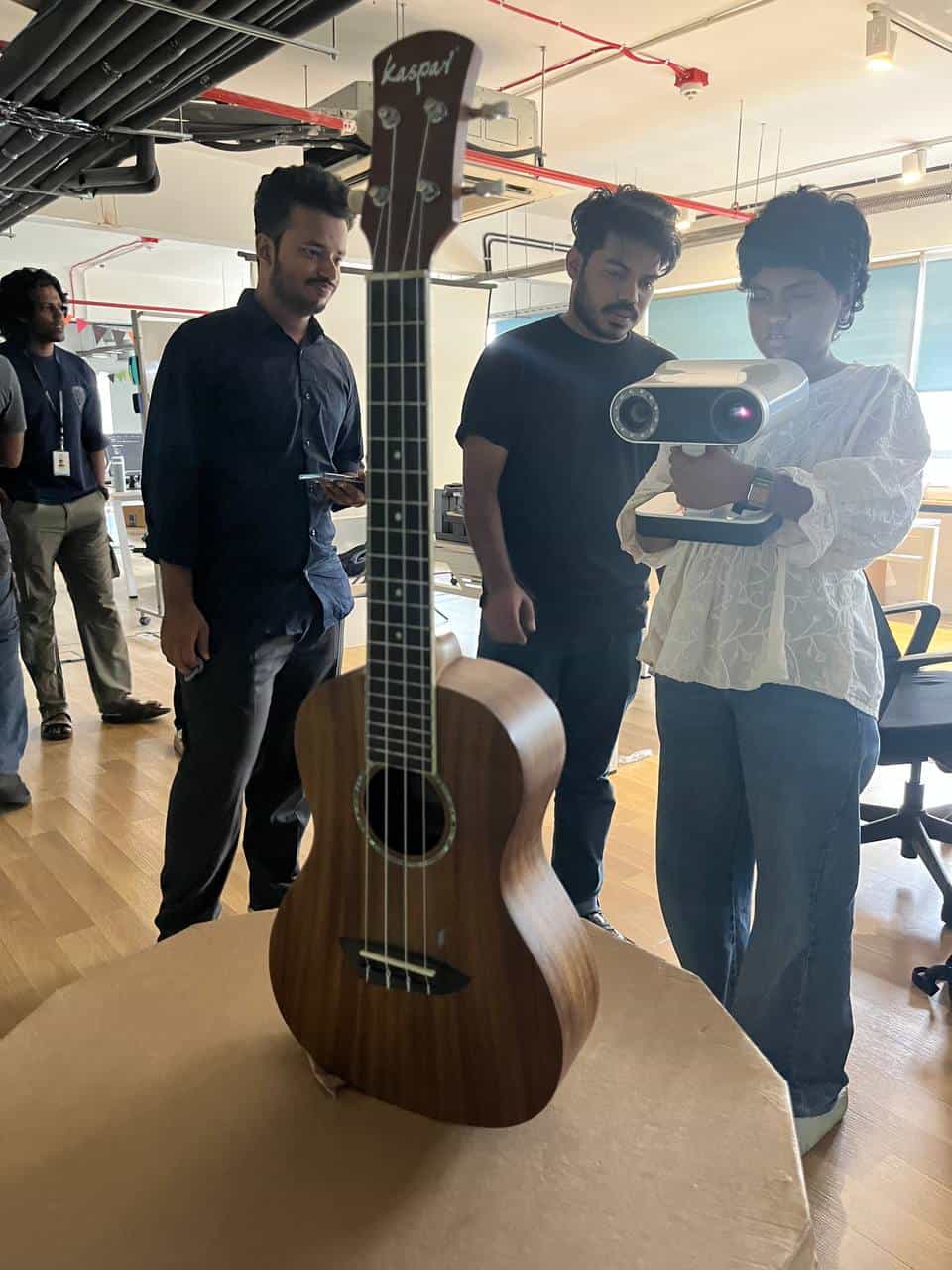
3D Scanning Process
First, we needed something to scan, and I saw a ukulele in the lab and went with it.
Limtation of 3D scanner
The object shall not be transparent, reflective, or too dark or else the scanner will have difficulty capturing accurate data. For scanning, we need to mask the object with a powder spray to create a matte surface, which helps the scanner capture the geometry accurately.
Before scanning, we had to set up the environment properly.
The scanner works best in well-lit conditions with minimal shadows and reflection.
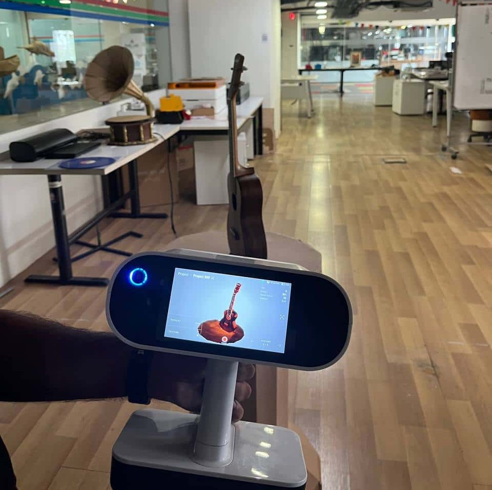
During scanning, we had to move the scanner around the ukulele to capture all angles and details.
It was important to maintain a steady hand and keep the scanner at a consistent distance from the object for accurate data capture. For that in scanner screen there is ths square edges, if you move out of the object it keep alerts.
As there is only one scanner we have in the lab, my classmates also had to wait their turn.It might take time for masking, setting proper light and hanging Ukulele so that even bottom part can scan properly.
Even with those limitation, it was a good learning experience. It was interesting and fun to scan a real object and turn into a digital 3D model.
The ukulele has metallic parts that were reflective, so it was difficult to capture those areas accurately.
The scanner had trouble capturing the geometry of the metallic tuning pegs and strings, resulting in incomplete data in those regions.
Post-processing the scan data
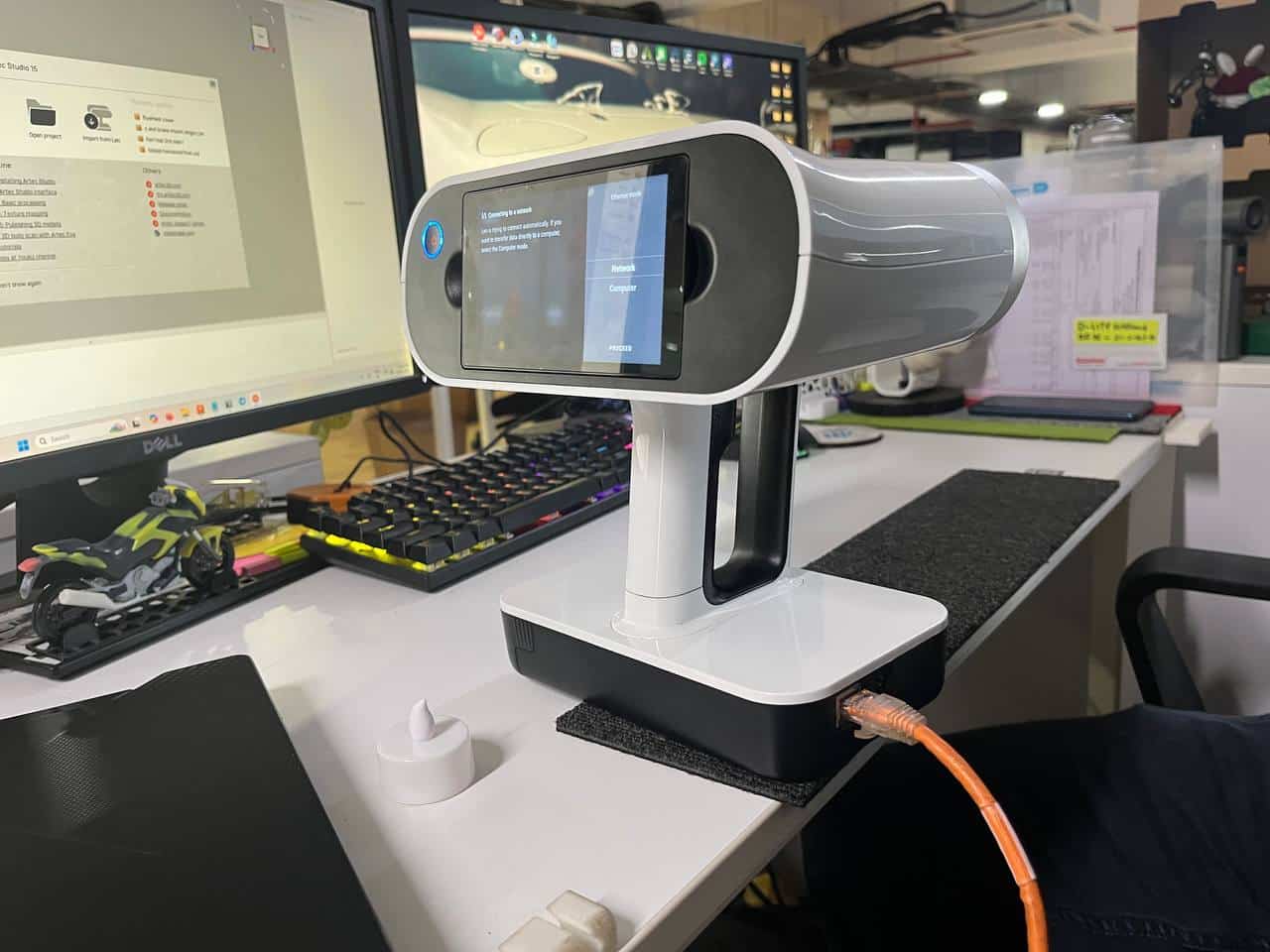
Transfering the scan data:
For this process, used the artec studio software; for importing the scan data, scanner can be connected in two ways; either by wifi or by connecting the scanner to a computer using a cable.
I connected through cable and transfered the scan data to the software.
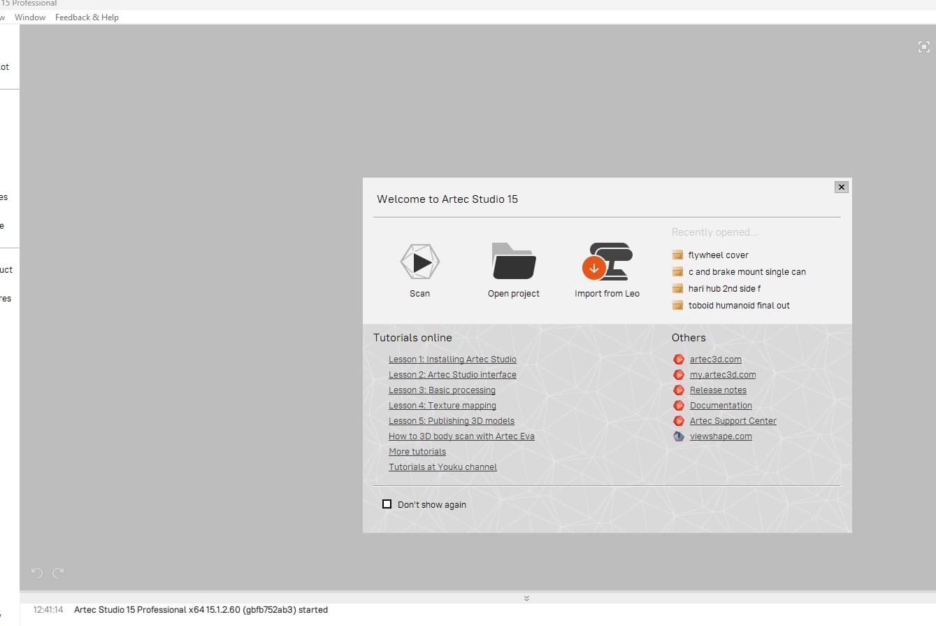
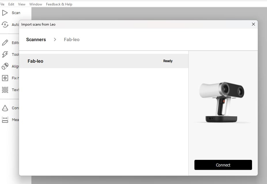
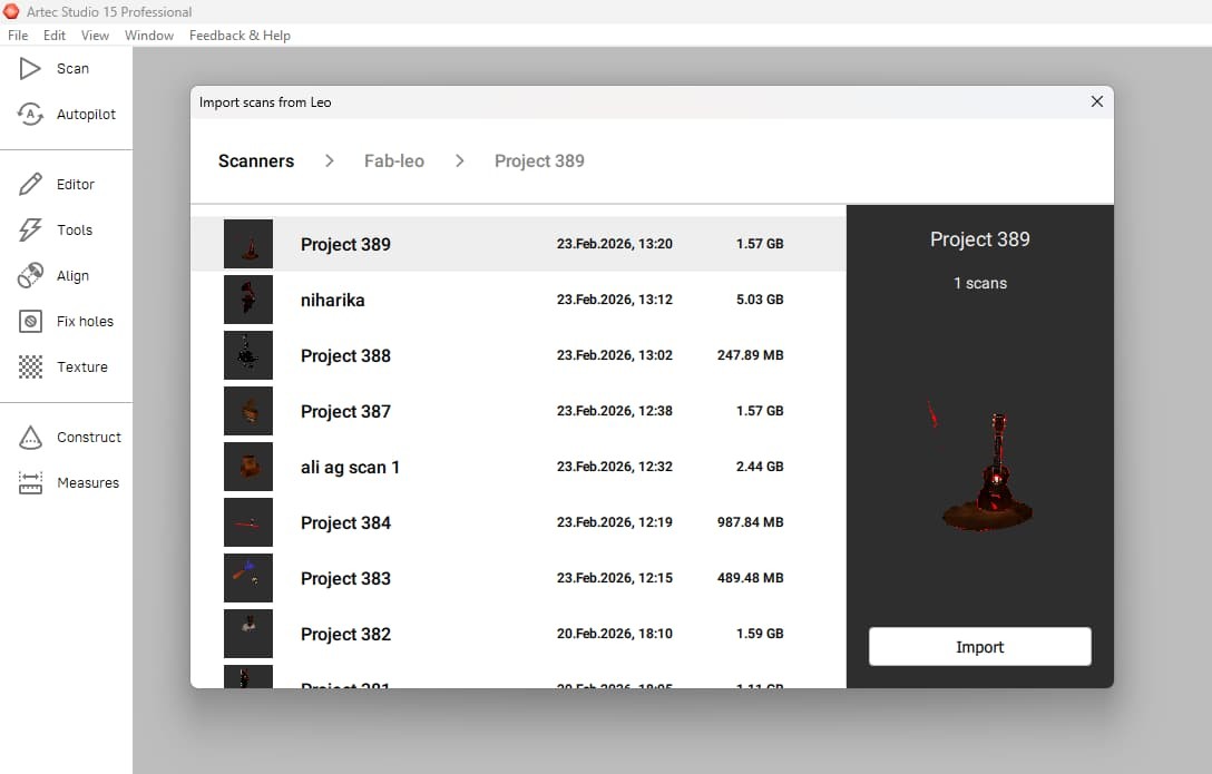
For importing, select import from leo >> scanner >> select the project. software provides various tools for post-processing, including:
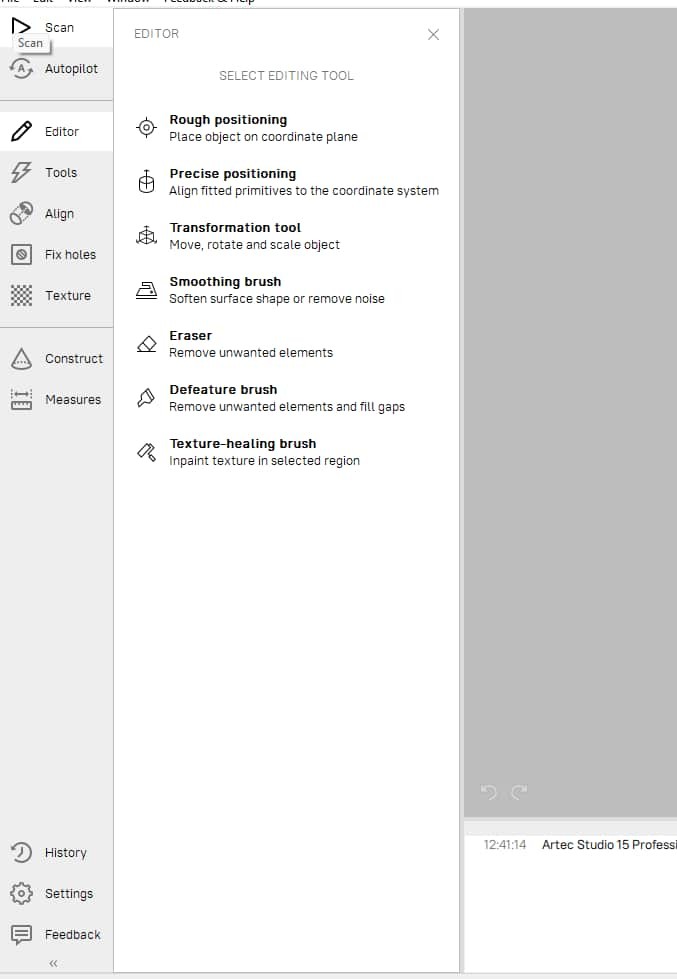
Positioning
from editor, there are different tools for positioning the model in 3D space, such as aligning it to a specific plane or moving it to a desired location.
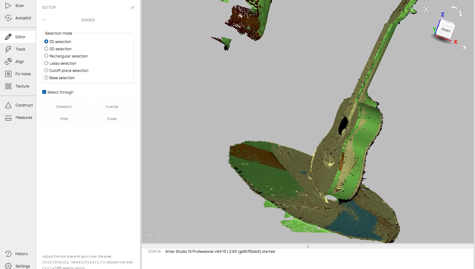
Eraser
from editor, I used the erasing tool to remove any unwanted elements of the model that were not part of the desired object.
There is multiple erasing modes, such as 3d selection, lasso, rectangle, and base selection are my favourite.
I used 3D selection and lasso to remove the unwanted elements and base selection to remove the base.
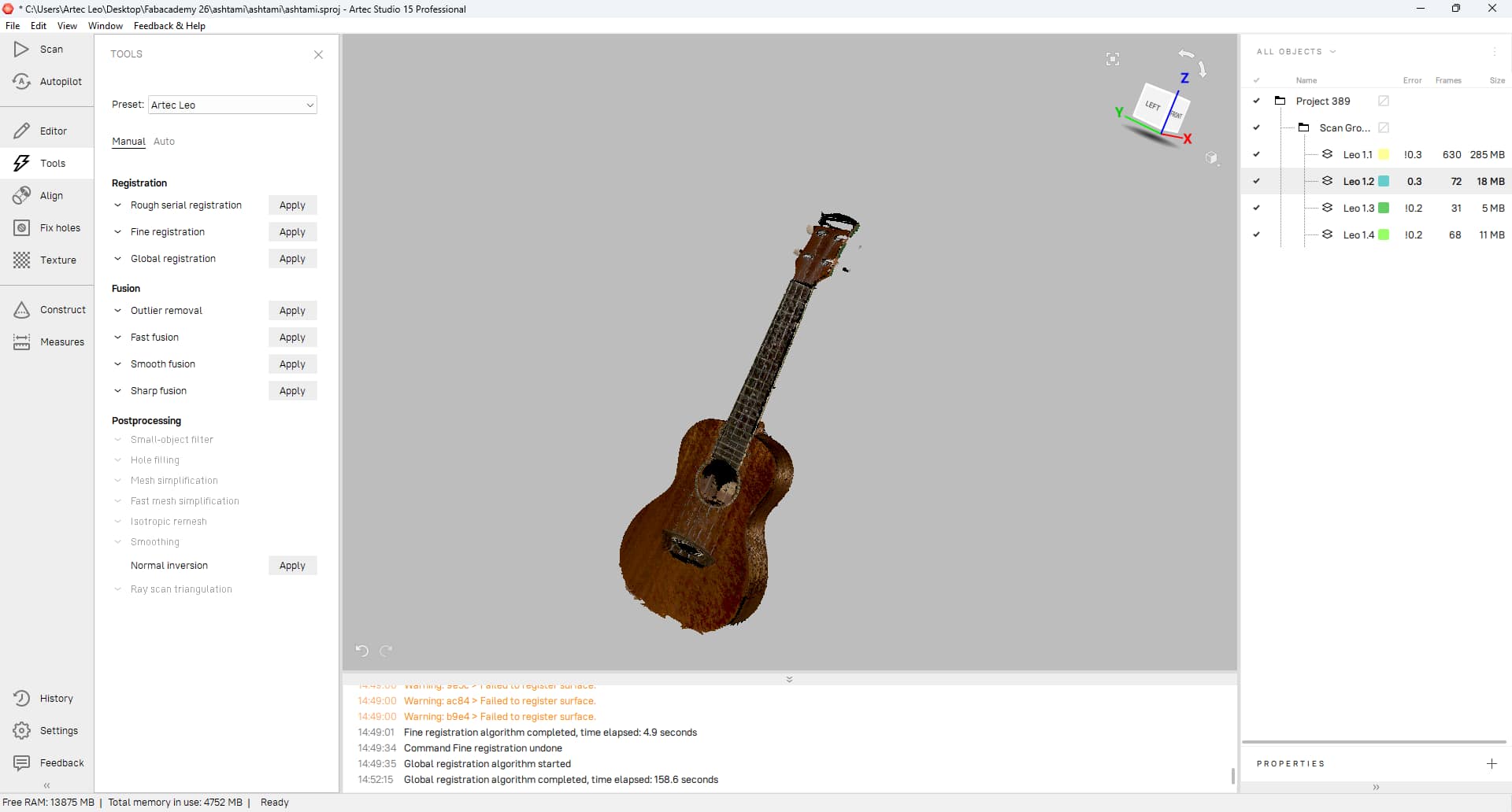
Registration
If the scan was done in multiple parts, registration is the process of aligning and merging those parts together to create a complete 3D model.
I need to merge my data, there are rough serial, fine, and global registration.
I tried all three, but the best result I got was from global registration and other two result as misalignment in model.
Sharp fusion
After registration, I used Sharp Fusion to combine all the aligned scans into a single 3D model. It helped create a cleaner mesh while keeping the details of the scanned object.
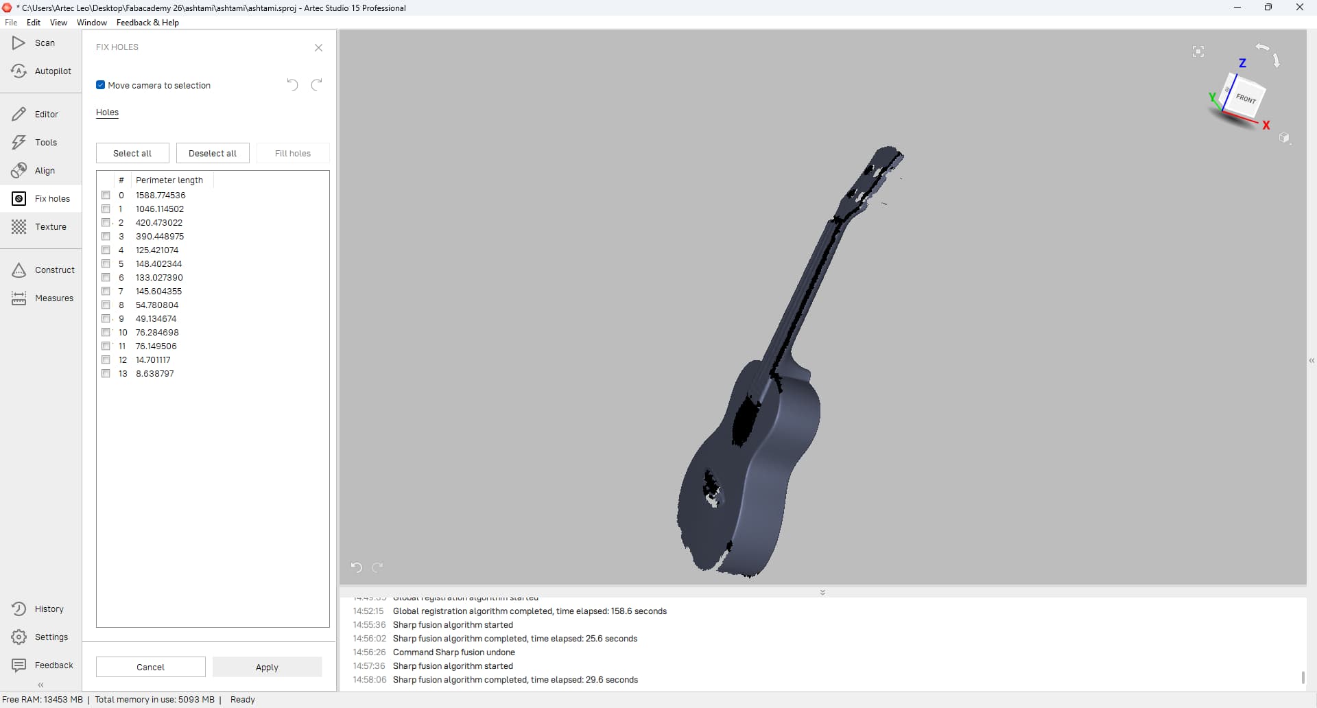
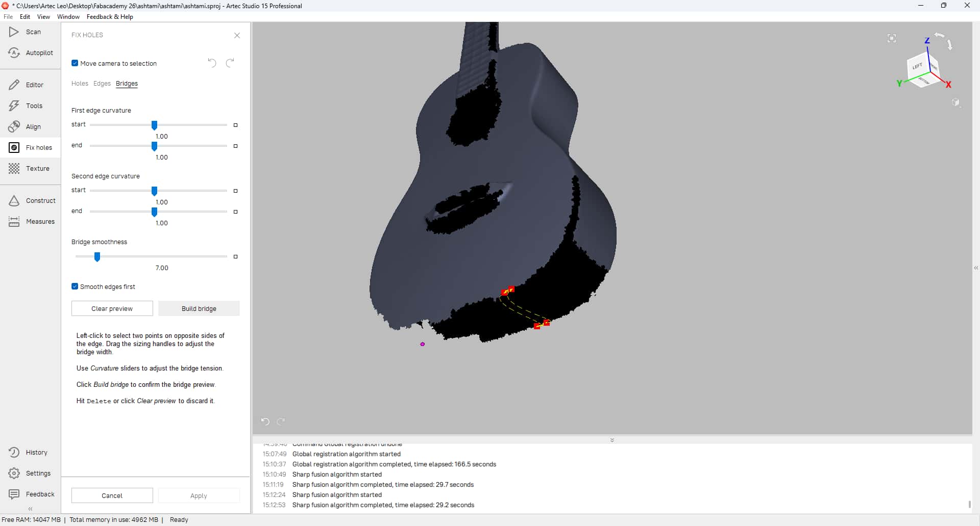
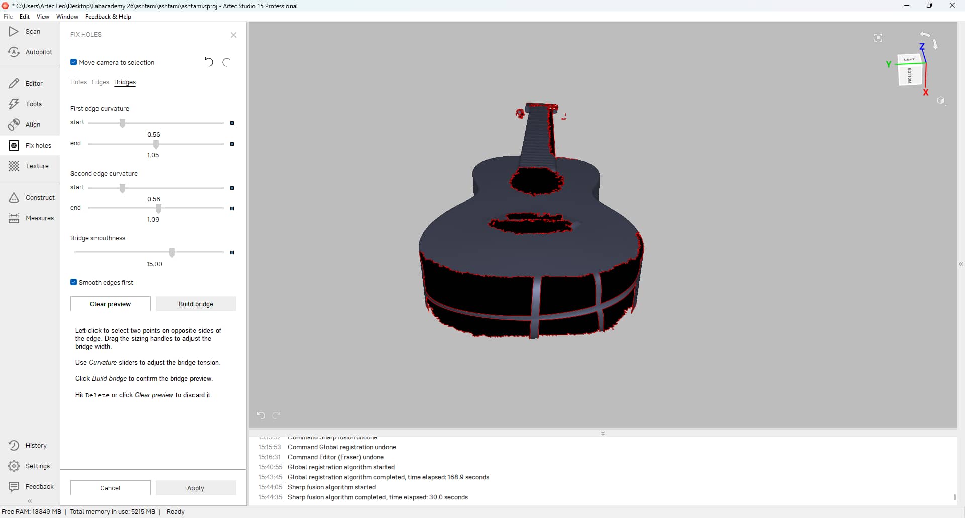
filling holes
After fusion, I noticed a few holes in the mesh where the scanner could not capture enough data. To fix this, I used the Bridge tool to connect the edges of the holes and fill the missing areas. This helped create a more complete model before exporting it as an STL file.
Texture fusion
This process involves combining the color and texture information captured during scanning with the geometric data to create a more realistic and visually appealing 3D model.
I used the texture fusion tool to apply the colors and textures from the scan onto the 3D model, resulting in a more lifelike representation of the ukulele.
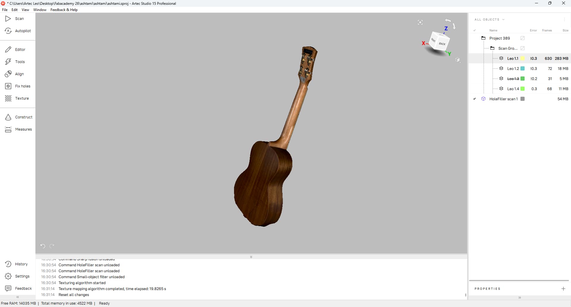
Finally, I exported the cleaned and processed 3D model as an STL file, which can be used for 3D printing or other applications.
Design Files
- Flaps: fusionfile
- flower: fusionfile
- Test flap: bambustudiofile
- Final Flaps: bambustudiofile
- Flower: bambustudiofile
- Ukulele: 3dscanfile